

Page 1
Single Deck Rotary Switches
Ø
.500
12,7[ ]
Ø
.200±.004
5,08
±
0,1[ ]
.625
15,88[ ]
REF
.375
9,53[
]
.250±.005
6,35
±
0,12[ ]
.180
4,57[ ]
.066±.010
1,68
±
0,25[ ]
Ø
.125±.001
3,18
±
0,02[ ]
.250±.005
6,35
±
0,12[ ]
.109±.010
2,77
±
0,25[ ]
Ø
.326
8,28[ ]
18°
.340±.005
8,64
±
0,12[ ]
18°
10X
36°
.314±.008
7,98
±
0,2[ ]
Ø
CIRCLE OF TERMINAL
CENTERS
.200
±
.010
5,08
±
0,25[ ]
.094±.005
2,39
±
0,12[ ]
11X Ø
.015
+.003
-.002
0,38
+0,07
-0,05
[ ]
.072±.005
1,83
±
0,12[ ]
12X Ø
.015
+.003
-.002
0,38
+0,07
-0,05
[ ]
TERMINAL VIEW
1 POLE
TERMINAL VIEW
2 POLE
HOUSING
FLAT
SHAFT FLAT
POS.1
3/8-32 UNEF-2A
THREAD
COMMON TERMINAL
TERMINAL 1
TERMINAL 1
COMMON 1
COMMON 2
RECOMMENDED PANEL CUT-OUT
POSITI0N 1
.345
+.003
-.000
8,76
+0,07
-0,00
[ ]
Ø
.375
+.005
-.000
9,53
+0,12
-0,00
[ ]
Ø.008 [0,2]
Ø.008 [0,2]
RECOMMENDED PCB LAYOUT
(VIEWED FROM SWITCH SIDE OF PCB)
TERMINAL 1
TERMINAL 1
1 POLE LAYOUT
2 POLE LAYOUT
*CUSTOMER TO ESTABLISH PCB DATUMS FOR HOLE PATTERN PLACEMENT
*
*
12X Ø
.024±.004
0,61
±
0,1[ ]
11X Ø
.024±.004
0,61
±
0,1[ ]
Ø
.200
5,08[ ]
Ø
.200
5,08[ ]
.072
1,83[ ]
36°
36°
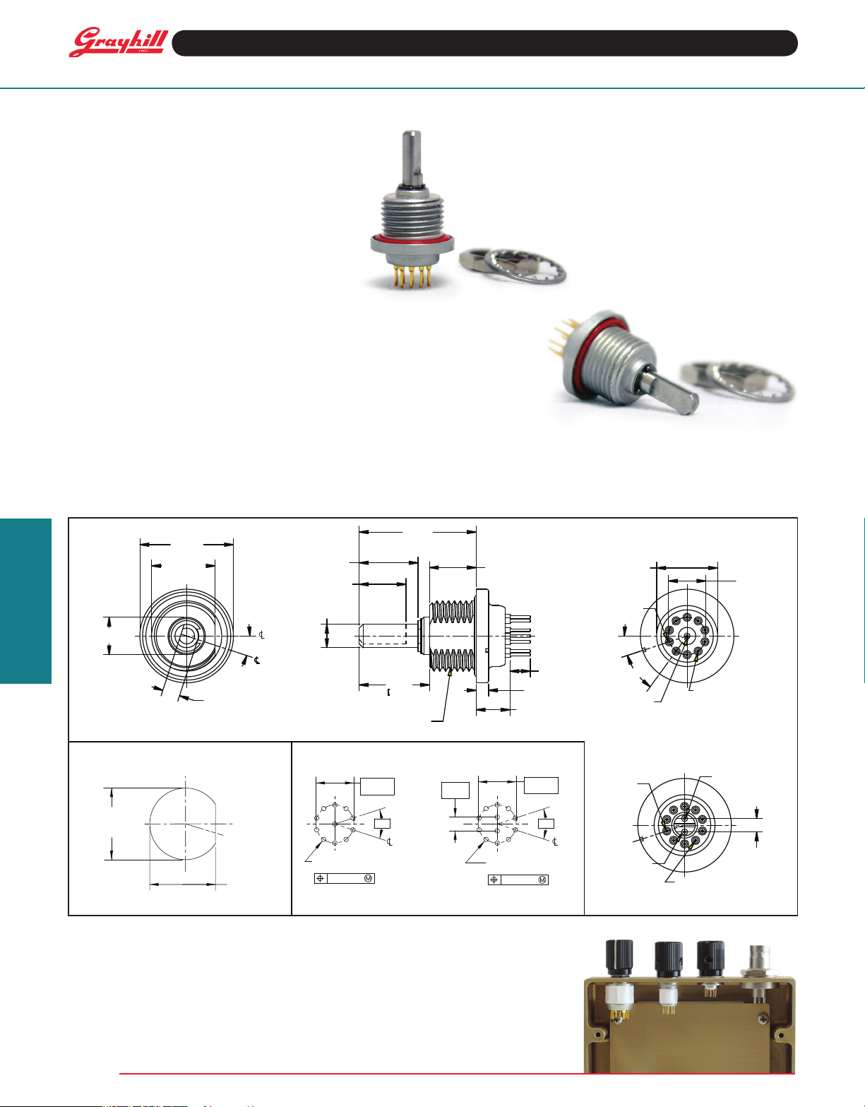
SERIES 77
0.5" Diameter, 200 mA
0.18" Behind Panel
FEATURES
• Small Size - Minimal Space Required
Behind Panel
• Available with Continuous Rotation
or a Fixed Stop
• High Stop Strength
• Shaft and Panel Seal
• Process Seal available
• Single Deck with 1 or 2 Poles
APPLICATIONS
• Handheld Radios
• Handheld Medical Devices
• Night Vision Products
• Laser Aiming Devices
Rotary Switches
DIMENSIONS in inches [and millimeters]
Unless otherwise specied, tolerances are ± .015 inch and ± 3 degrees
Recommended Mounting Torque: Tighten
mounting hex nut to 12 in-lb (15 in-lb max).
Before applying torque, rotation of the switch
housing must be constrained by the housing
at via the "Recommended Panel Cut-Out"
or similar method. Constraining by PCB or
anything soldered to the terminals will result
in damage to the switch
Grayhill, Inc. • 561 Hillgrove Avenue • LaGrange, Illinois 60525-5997 • USA • Phone: 708-354-1040 • Fax: 708-354-2820 • www.grayhill.com
Grayhill part number and date code marked
on label. Customer part number marked on
request.
Series
50
Series
Series
75
77
Page 2
RATED LOADS
Switches are rated to make and break the following loads:
Single Deck Rotary Switches
Environment
Condition
Atmospheric
Pressure
Reduced
Pressure
(70,000 feet)
Lamp Load Inductive Load (140mH) Resistive Load
Milliamp Volts Milliamp Volts Milliamps Volts
50 28 VDC 30 28 VDC 50 12 VDC 25,000
One cycle is 360-degree rotation and a return
through all switch positions to the starting
position.
Electrical Specifications
Low Level Circuit Rating: 10 milliamperes,
30 millivolts DC or Peak AC open-circuit voltage,
25,000 cycles
Contact Resistance: 50 milliohms max
(15 milliohms initially).
100 milliohms max low level.
Insulation Resistance: 50,000 Mohms initially
(10,000 Mohms after life) at 100 VDC
Voltage Breakdown: 600 Vac initially,
250 Vac after life
Mechanical / Environmental Ratings
Operating Temperature: -40°C to +85°C
Storage Temperature: -65°C to +100°C
Altitude: 70,000 feet
Rotational Torque: 3 in-oz min. to 7 in-oz
max
Stop Strength: 7.5 inch pounds min
Withstanding Shaft Push Force: 100
pounds
Weight: 4.7 grams with hardware
3.9 grams without hardware
Cycles
10 28 VDC 25,000
50 28 VDC 10,000
100 28 VDC 7,500
200 28 VDC 5,000
50 115 Vrms 10,000
100 28 VDC 7,500
Vibration: MIL-DTL-3786, MIL-STD-202,
method 204, condition "B"
Shock: MIL-DTL-3786, Medium impact per
MIL-STD-202, Method 213.
Moisture Resistance: MIL-DTL-3786, MILSTD-202, Method 106
Salt Spray: MIL-DTL-3786, MIL-STD-202,
method 101, condition "B"
Explosion Proof: MIL-DTL-3786, MIL-STD
202, method 109
Immersion: With shaft operation – Shaft and
panel seal withstands water pressure of 15
psi minimum per MIL-DTL-3786 (Equivalent to
33ft [10m] immersion for 30 minutes).
Without shaft operation - Shaft and panel
sealed to withstand 74ft [22m] immersion for 2
hours, MIL-DTL-810G Method 512.5.
Sand and Dust: MIL-DTL-3786, MIL-STD202 Method 110
Flux Seal (Process Sealed Versions): Level
1 & 2 per MIL-DTL-3786.
Materials and Finishes
Switch Base: Diallyl Phthalate per MIL-M-14
Bushing: Zinc alloy, tin zinc plating
Detent Rotor: Nylon
Detent Balls: Steel, nickel-plated
Contact Spring: Tinned music wire
Detent Spring: Stainless steel
Shaft: Stainless steel
Shaft Seal: Ethylene Propylene
Panel Seal: Silicone
Rotor Contact: Silver cad-oxide, gold-plated
Terminals and Common: Brass, gold plate
.00002" minimum thickness over silver plate
.0003" minimum.
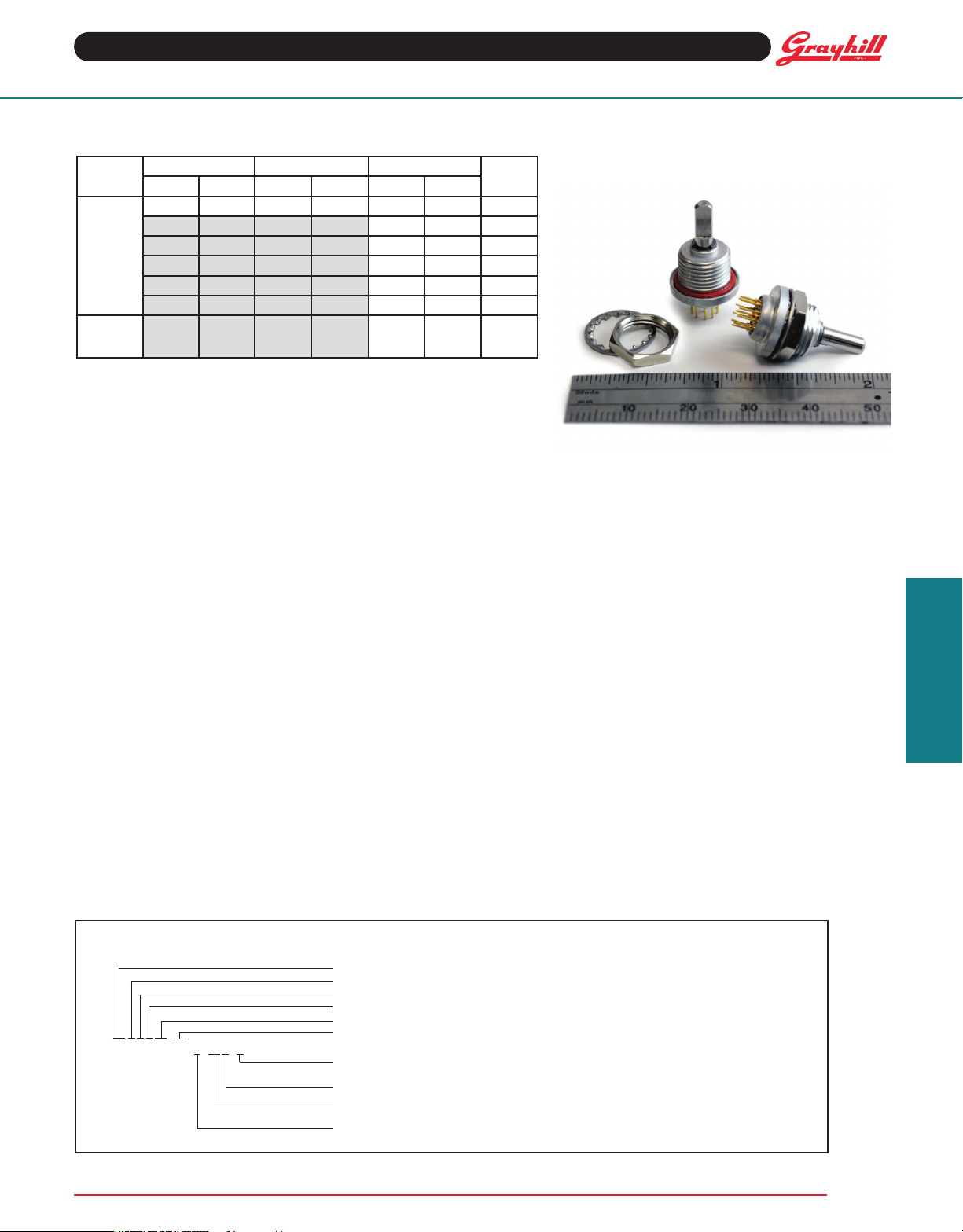
Mounting Hardware: One mounting nut .089"
thick by .433" across ats and one external tooth
lockwasher supplied with each switch. Mounting
nut is brass, nickel plated and lockwasher is
stainless steel.
Additional Characteristics
Contact Type: Non-shorting, wiping contacts
Terminals: Switches are provided with the full
circle of terminals regardless of the number of
active positions.
Rotary Switches
Contact Grayhill if the life limiting criteria is more critical than those listed, if the required cycles of operation are greater than those listed,
if a larger make and break current is required than the one listed for the desired number of cycles, or if elevated temperatures or reduced
pressures are part of the operating environment.
ORDERING INFORMATION
Series 77
S = Shaft & Panel Sealed, leave blank for no shaft & panel seal
P = PC Terminals
T = Process Seal, Leave blank for no process seal
Angle of throw: 36 = 36°
77SPT36-01-1-10N-F
For prices and discounts, contact a local Sales Ofce, an authorized local Distributor, or Grayhill.
Grayhill, Inc. • 561 Hillgrove Avenue • LaGrange, Illinois 60525-5997 • USA • Phone: 708-354-1040 • Fax: 708-354-2820 • www.grayhill.com
Number of Decks: 01 Only
Stop arrangement: Needed only with 1 pole switches with maximum positions.
Leave blank for continuous rotation; add F for fixed stop.
Contacts: N = Non-shorting
Positions per pole: 02 up to 10 positions (1 pole),
02 up to 05 positions (2 poles)
Poles per deck: 1 or 2
 Loading...