

Page 1
Single Deck Rotary Switches
.937 ± .020
(23,80 ± 0,51)
DIA.
.219 ± .005
(5,56 ± 0,13)
36° ± 5°
.564 ± .020
(14,33 ± 0,51)
COMMON
APPROX.
.750 (19,05) DIA. OVER
TERMINAL ENDS AT
INSERTION END
.109 ± .015
(2,77 ± 0,38)
.531 ± .020
(13,49 ± 0,51)
.050 ± .002
(1,27 ± 0,05)
.096 ± .003
(2,44 ± 0,08)
BASE TERMINAL
.020 ± .002
(0,51 ± 0,05)
COMMON TERMINAL
.016 ± .002
(0,41 ± 0,05)
.187 ± .005
(4,75 ± 0,13)
36° TYP.
REF.
.113 (2,87)
TYP.
.213
(5,41)
TYP.
.347 (8,81)
TYP.
.363 (9,22)
TYP.
.525
(13,34)
TYP.
.294 (7,47)
TYP.
.250 + .001/ – .002
(6,35 + 0,03/ – 0,05)
DIA.
1.015 ± .015
(25,78 ± 0,38)
DIA.
TERMINAL 9 IN LINE
WITH KEYWAY
BUSHING KEYWAY
.066 ± .002 (1,68 ± 0,05) WIDE
.036 ± .005 (0,91 ± 0,13) DEEP
FROM THE .375 (9,53) DIAMETER
3/8-32UNEF-2A
THREAD
.578 ± .030
(14,68 ± 0,76).250 ± .020
(6,35 ± 0,51)
.250 ± .020
(6,35 ± 0,51)
.312 ± .020
(7,93 ± 0,51)
7
8
9
10
1
2
3
4
6
5
C
L
OF
BUSHING
KEYWAY
ONE POLE
C
1
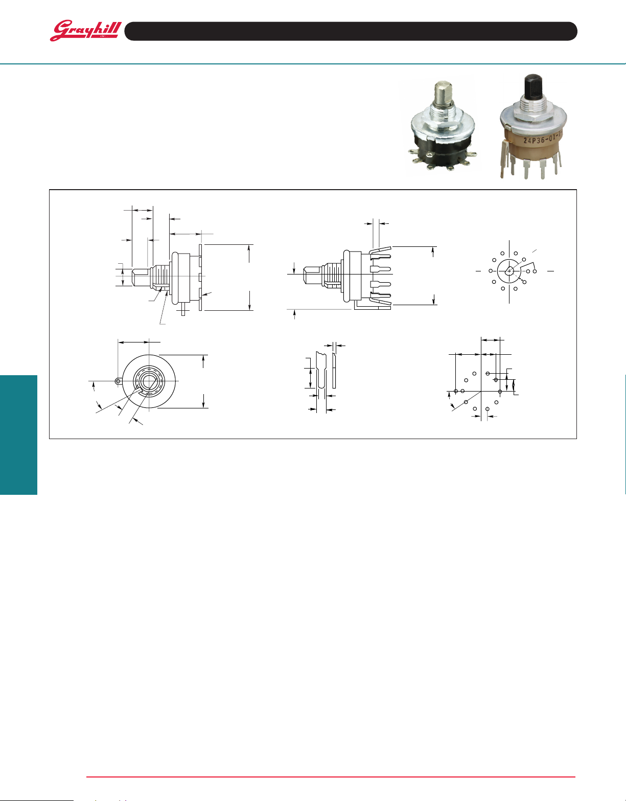
SERIES 24
1" Diameter, 1 Amp,
.580" Behind Panel
FEATURES
•PositiveDetentProvides
Operator Feedback
•StainlessSteelorPlastic
Shaft Option
•UnsurpassedPerformance
in Numerous Applications
DIMENSIONS in inches (and millimeters)
Solder Lug PC Mountable
Typical Terminal Detail ( PC
Mount)
Circuit Diagram
Solder Lug and PC Mount
(Switch is viewed from shaft end.)
Note: Common Terminal is
located above Base Terminal 10.
Terminal Location (PC Mount)
Rotary Switches
SPECIFICATIONS
Electrical Rating
Rated: To make and break the following loads:
1 amp at 115 Vac, resistive; 0.5 amp at 220 Vac
resistive; 1/4 amp, 115 Vac inductive; 1/50 amp,
115 Vdc inductive; 1/10 amp, 6 to 28 Vdc inductive; 1/10 amp, 115 Vdc resistive; 1 amp, 6 to 28
Vdc resistive; to carry 10 amps continuously.
Contact Resistance: 10 milliohms initial.
After 25,000 cycles of operation 20 milliohms
maximum.
Insulation Resistance: 50,000 Mohms
minimum initially
Voltage Breakdown: 1,000 Vac, (500 Vac, or
better after most environmental tests).
Life Expectancy: 100,000 mechanical cycles
of operation normally. NOTE: Actual life is determined by a number of factors, including electrical
loading, rate of rotation, and environment, as
well as maximum contact resistance, minimum
insulation resistance, and minimum voltage
breakdown required at the end of life.
Materials and Finishes
Switch Base: Mel amine per (MIL-M-14)
ASTM-D-5948
Cover, Stop Washers, Bushing: Brass, tin/
zinc-plated
Contacts: Both shorting and non-shorting
wiping contacts have over 300 grams contact
force.
Retaining Rings, Stop Arms, and Thrust
Washers: Stainless steel
Grayhill, Inc. • 561 Hillgrove Avenue • LaGrange, Illinois 60525-5997 • USA • Phone: 708-354-1040 • Fax: 708-354-2820 • www.grayhill.com
Grayhill part number and date code marked on label. Customer part number marked on request.
STANDARD OPTIONS
Special Terminals
RFI Grounding
Not available through distributors.
ORDERING INFORMATION
Switches are single deck, one pole switches
of 2 to 10 positions. They have plastic or steel
shaft, with solder lug or PC terminals, with either
shorting or non-shorting contacts (plastic shaft
PC mount in non-shorting only). Ten position
switches have continuous rotation; fixed stop
switch with a metal shaft is available by special
order. Base part numbers are as follows:
Lug style, steel shaft: 24001-X*
Lug style, plastic shaft: 24B36-01-1-X*
PC style, steel shaft: 24878-X*
PC style, plastic shaft: 24P36-01-1-X*
The X is replaced with the number of positions
required (02, 03, etc.) Complete the part number
by adding N for non-shorting contacts or S for
shorting contacts.
Available from your local Grayhill
Distributor.
For prices and discounts, contact a local
SalesOfce,anauthorizedlocal
Distributor or Grayhill.
Detent Balls: Steel, nickel-plated
Shafts: Stainless steel, or plastic
Detent: Opposing spring and ball in a hill and
valley raceway.
Detent Springs: Tinned music wire
Terminals (except common): Brass, tin
plated.
Rotor Contact: Steel shaft version—phosphor
bronze, silver-plated .0003" minimum. Plastic
shaft version—silver alloy.
Stator (Base) Contact: Brass, silver-plated
.0003" minimum
Common Plate, including Solder Lug or PC
Tab: Brass, silver-plated .0003" minimum
Rotor Mounting Plate: Nylon fabric-based
laminated phenolic per MIL-T-15047
Mounting Nut:Brass,tin/zinc-platedorstain-
less steel.
Additional Characteristics
Stop Strength: 12 in-lbs
Rotational Torque:12in-ozs
Shaft Flat Orientation: Opposite point of contact
(See circuit diagram.)
Environmental: These switches have passed
the following environmental testing: Altitude and
temperature, 100 hour salt spray; Vibration 10 to
500 cps; Shock 30-G; Humidity; Fungus.
PC Mount: PC Switches are furnished with 10
base terminals for mounting purposes.
 Loading...