

Page 1

RACKS
5
4 Channel
FEATURES
• Use for Isolating and Coverting Signal Types to
Standard Logic Voltages
• Terminal Block Connection for Input and Output
• Available for Standard and G5 I/O Modules
• Panel and DIN Rail Mount Versions
• UL, CSA Certified
4 CHANNEL RACK: Standard
System 50
Part No. 70RCK4
Dimensions are shown in inches
(and millimeters).
All tolerances are ± 0.010 (0,25)
unless otherwise specified.
MODULE SHOWN FOR
REFERENCE ONLY
NOTE: MAXIMUM
TERMINAL SCREW
TORQUE NOT TO
EXCEED 5 IN-LBS.
STATUS LED
3.3K RESISTOR
5 AMP FUSE
TERMINAL STRIP FOR
FIELD WIRING
STANDOFF I.D. 0.15 ( 3,8),DIA.
(4 PLACES)
CLEARANCE FOR #6 SCREW
9 8 7 6 5 4 3 2 1
9 8 7 6 5 4 3 2 1
4.00 (101,6)
0.25 (6,4)
9 POSITION TERMINAL
STRIP FOR GROUND
AND LOGIC SIGNALS
B AC OUTPUT R DC OUTPUT
Y AC INPUT W DC INPUT
3.00
(76,2)
3.50
(88,9)
0.25 (6,4)
4.50 (114,3)
2.20 (55,9)
MAX.
0.75 (19,1)
4 CHANNEL RACK: G5
System 50
Part No. 70GRCK4
Dimensions are shown in inches
(and millimeters).
All tolerances are ± 0.010 (0,25)
unless otherwise specified.
.36
,34)
.75
(19,05)
4.00
(101,6)
.25
(6,35)
9 POSITION
TERMINAL
STRIP FOR
FIELD WIRING
SWAGED
STANDOFF
THRU HOLE
.15 (3,81) DIA.
(4 PLACES)
(CLEARANCE
FOR #6 SCREW)
9 POSITION
TERMINAL
STRIP FOR
CONTROL
LOGIC
DIN-RAIL CARRIER
3.25 (82,55)
2.75 (69,85)
R
B
DC OUTPUT
AC OUTPUT
W
Y
DC INTPUT
AC INTPUT
1 2 3 4 5 6 7 8 9
9 8 7 6 5 4 3 2 1
.76 (19,30)
4.27
(108,46)
4.70
2.75
(119,38)
(69,85)
NOTE: MAXIMUM TERMINAL
SCREW TORQUE NOT TO
EXCEED 5 IN-LBS.
DIN-Rail
Panel Mount
Mount
Grayhill, Inc. • 561 Hillgrove Avenue • LaGrange, Illinois 60525-5997 • USA • Phone: 708-354-1040 • Fax: 708-354-2820 • www.grayhill.com
System 50
4
Page 2
System 50
1
9
G
3
C
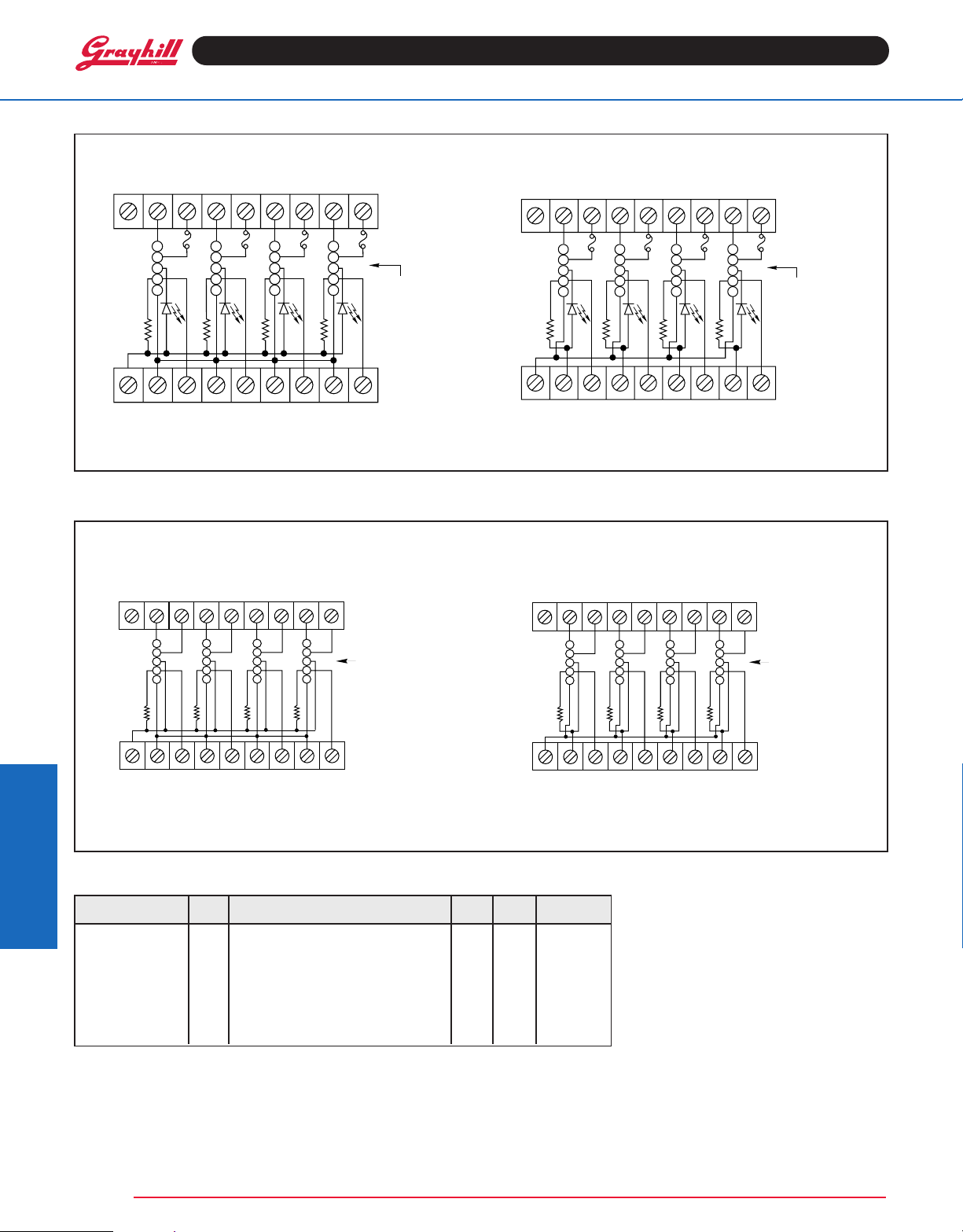
SCHEMATICS: Part No. 70RCK4
70RCK4 For Negative True Logic Only
2 3 4 5 6 7 8
N/C
1
2
0 1 2 3
3
4
5
3.3K
1 2 3 4 5 6 7 8 9
+VCC
GND
LOGIC
GND
LOGIC
GND
LOGIC
GND
LOGIC
FIELD WIRING
TERMINAL STRIP
FUSE
5A
MODULE
POSITION
TERMINAL STRIP
FOR LOGIC AND
GROUND SIGNALS
SCHEMATICS: Part No. 70GRCK4
70GRCK4 and 70GRCK4-DIN For Negative True Logic Only
N
1 2 3 4 5 6 7 8 9
1
2
3
0 1 2 3
4
5
PULL-UP
RESISTOR
.3 KΩ
1 2 3 4 5 6 7 8 9
BARRIER STRIP
FOR FIELD WIRING
OF MODULE
INPUT/OUTPUT
MODULE
LOCATION
CONTROL
BARRIER
STRIP
70RCK4R For Negative or Positive True
Logic
1 2 3 4 5 6 7 8 9
N/C
1
2
0 1 2 3
3
4
5
3.3K
1 2 3 4 5 6 7 8 9
GND
+VCC
LOGIC
+VCC
LOGIC
+VCC
LOGIC
+VCC
70GRCK4R and 70GRCK4R-DIN For Negative
or Postive True Logic
NC
1 2 3 4 5 6 7 8 9
1
2
3
0 1 2 3
4
5
PULL-UP
RESISTOR
3.3 KΩ
1 2 3 4 5 6 7 8 9
FIELD WIRING
TERMINAL STRIP
FUSE
5A
MODULE
POSITION
TERMINAL STRIP
FOR LOGIC AND
GROUND SIGNALS
LOGIC
BARRIER STRIP
FOR FIELD WIRIN
OF MODULE
MODULE
LOCATION
CONTROL
BARRIER
STRIP
GND
System 50
+VCC
ORDERING INFORMATION
LOGIC
GND
LOGIC
GND
LOGIC
GND
(modules ordered separately)
Part Number I/O Description UL CSA Style
70RCK4 4 Negative true logic X X Standard
70RCK4R 4 Positive or negative true logic* X X Standard
70GRCK4 4 Negative true logic X X G5
70GRCK4R 4 Positive or negative true logic* X X G5
70GRCK4-DIN 4 Negative true logic–
70GRCK4R-DIN 4 Positive or negative true logic*– X X G5
DIN rail mount
*Note: Positive True Logic applies to output modules only.
System 50
5
Grayhill, Inc. • 561 Hillgrove Avenue • LaGrange, Illinois 60525-5997 • USA • Phone: 708-354-1040 • Fax: 708-354-2820 • www.grayhill.com
LOGIC
DIN rail mount
+VCC
GROUND
XX G5
LOGIC
+VCC
LOGIC
+VCC
LOGIC
+VCC
LOGIC
.
Available from your local Grayhill Distributor. For prices and discounts, contact a local
Sales Office, an authorized local Distributor, or
Grayhill.
 Loading...