

Page 1
A
C
12
84
C
L
C
L
COMMON TERMINAL
.300
(7,62)
.150 (3,81)
2 PLACES
.100 (2,54)
2 PLACES
.200 (5,08)
Series Code
Adjustable
Mechanical Encoders
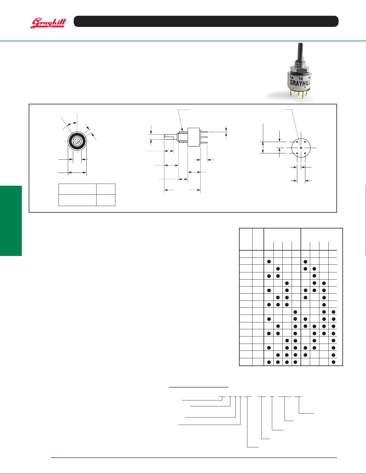
SERIES 26
Binary and Gray Code
DIMENSIONS in inches (and millimeters)
ANGLE A
.203 ± .003
(5,16 ± 0,10)
CROSS FLATS
.500 ± .015
(12,7 ± 0,38) DIA.
Optical and Mechanical
Encoders
OF BUSHING FLATS
C
L
POS. 0
C
L
.094 (2,39)
Maximum Switch Angle
Positions A
8 67.5°
16 33.75°
AVAILABLE CODES
• Hexadecimal
• Octal
• BCD (Adjusted)
• Quadrative
• Custom (4-Bit, 16 position maximum)
• RoHS Compliant
1/4-28 UNF-2A THREAD
.125 ± .003 DIA.
(Ø 3,18 ± 0,10)
.025 ± .005
.250 (6,35)
.375 (9,53)
.250 (6,35)
.957
(24,31)
REF.
Unless specied otherwise, all tolerances are ± .015 ( 0,38)
(0,64 ± 0,13)
.180 (4,57)
.332 (8,43)
3 PLACES
Grayhill part number and date
code marked on label. Customer
part number marked on request.
SPECIFICATIONS
Electrical Ratings
Rated: 25,000 cycles with logic compatible
loads. Make and break 200 mA.
Contact Resistance: 500 milliohms maximum
(less than 100 milliohms initially)
Insulation Resistance: 1000 megohms
minimum (10,000 megohms initially)
Dielectric Strength: 250 Vac minimum
Materials and Finishes
Panel Seal: Silicone Rubber
Shaft Seal: Fluorosilicone
Mounting Nut (mounting hardware–one
per switch): Brass, tin/zinc-plated
Internal Tooth Lockwasher (mounting
hardware): Steel,tin/zinc-plated
Detent Balls: Carbon steel, nickel-plated
Detent Spring: Pretinned music wire
Detent Rotor: Thermoplastic
Shaft, Stop Arm and Stop Pins: Stainless steel
Bushing: Zamak II tin/zinc alloy, zinc-plated
Switch Base: Diallyl phthalate
Printed Circuit Board: NEMA Grade FR-4.
Terminals: Brass, gold-plated over nickel plate
Contacts: Copper alloy, gold-plated over
nickel plate
Additional Characteristics
Rotational Torque: 4 to 8 oz-in initial
Vibration Resistance: 10 to 55 Hz at
0.060" double amplitude; no damage and
no contact openings per MIL-STD-202,
Method 201A
Shock Resistance: Passes medium
requirement MIL-DTL-3786 (MIL-STD-202,
Method 213)
Stop Strength: 5 in-lbs minimum
Relative Humidity: 90-95% at 40oC for
240 hours (MIL-STD-202 Method 103, Test
Condition A)
Shaft and Panel Seal
All switches are provided with a shaft and
panel seal.
CODE AND TRUTH TABLE
BCD Output* Gray Output*
1 2 4 8 1 2 4 8
Code
Position
Switch
Position
1 0
2 1
OPTIONS
Adjustable Stop Switches
The switch may have continuous rotation, or
be adjusted to limit the rotation. The panel
seal ring can be removed to expose the stop
pin holes on the front of the switch. Two stop
pins and panel seal o-ring are supplied with
the switch. One or both may be used to limit
the rotation as desired.
3 2
4 3
5 4
6 5
7 6
8 7
9 8
10 9
Custom encoders with options such as custom
code output, 1/4” shaft diameter, factory set
stops and longer shaft terminal lengths are
available by contacting the Grayhill sales
office at 708.482.2123.
11 10
12 11
13 12
14 13
15 14
ORDERING INFORMATION
Available from your local Grayhill Distributor.
For prices and discounts, contact a local Sales
16 15
*Dot indicates terminal tied to common.
Ofce, or an authorized local Distributor or
Grayhill through grayhill.com/where-to-buy.
26GSD22-01-1-16S-C
Grayhill, Inc. • 561 Hillgrove Avenue • LaGrange, Illinois 60525-5997 • USA • Phone: 708-354-1040 • Fax: 708-354-2820 • www.grayhill.com
Output Code:
G = Gray, A = BCD
Sealed
Stops:
D = Adujustable,
Blank = Continuous or Fixed
Poles: 1
Decks: 1
Angle of Throw:
22 = 22.5º, 45 = 45º
C = Continuous,
F = Fixed,
Positions:
08S, 16S, or AJS for adjustable
Blank =
 Loading...