

Page 1

IP Users Manual
Revision A6
Friday, January 26, 2001
Page 2

Grayhill EZCom IP Users Manual Rev A6 1/26/2001
Table Of Contents
Getting Started.....................................................................................................................4
Initialization ..................................................................................................................... 4
EZCom-IP Explorer Introduction ................................................................................. 4
Point-to-Point Link Example........................................................................................ 6
Windows TCP/IP Set Up ...................................................................................................13
Multipoint Store-&-Forward Example........................................................................14
Technical Reference..........................................................................................................18
Introduction ................................................................................................................... 18
Protocols And Protocol Architecture............................................................................. 19
A Simple Model.........................................................................................................20
The TCP/IP Protocol Architecture............................................................................. 21
TCP/IP Communications............................................................................................... 23
The TCP/IP Protocol Stack ....................................................................................... 23
Application Layer....................................................................................................... 23
Transport Layer......................................................................................................... 23
User Datagram Protocol............................................................................................ 25
Network Layer ........................................................................................................... 26
Overview of TCP/IP Addresses.................................................................................26
Internet Protocol Routing........................................................................................... 28
The ROUTE Utility Program...................................................................................... 31
Finding Another Machine’s Address ......................................................................... 32
Ethernet Physical Layer................................................................................................ 34
MAC Frame............................................................................................................... 34
Routing, Putting All of the Pieces Together .............................................................. 34
Subnetting..................................................................................................................... 35
How Do You Subnet?................................................................................................ 35
Determining Your Addressing Needs .................................................................... 35
Remembering Binary................................................................................................. 35
Defining Your Subnet Mask................................................................................... 36
Finding Out How Many Networks, How Many Hosts............................................. 37
Subnet IDS............................................................................................................. 37
EZCom IP Routing........................................................................................................ 40
Introduction................................................................................................................40
Indicators and Connectors ........................................................................................ 43
Grayhill EZCom-IP Explorer Program ...............................................................................44
Introduction................................................................................................................44
Views......................................................................................................................... 44
Menus & Tool Bar...................................................................................................... 45
Control Tabs.............................................................................................................. 46
Troubleshooting Guide ......................................................................................................50
LED Activity B ............................................................................................................... 50
No Ethernet Link indicator............................................................................................. 50
Link Test Failed......................................................................................................... 50
Ping Failed to Respond............................................................................................. 51
Ethernet (CSMA/CD).........................................................................................................52
Precursors................................................................................................................. 52
Description of CSMA/CD........................................................................................... 53
Page 2 Of 54
Page 3

Grayhill EZCom IP Users Manual Rev A6 1/26/2001
List Of Tables & Figures
Table 1, Factory Default Settings.......................................................................................4
Table 2, Point-To-Point Setup Parameters ........................................................................ 6
Table 3, Example II, EZCom-IP Radio Settings...............................................................14
Table 4, Example II Device IP Addresses........................................................................ 15
Table 5, Routing Table for 192.168.1.2 (EZCom-IP radio)............................................... 16
Table 6, Routing Table for 192.168.1.1 (PC) ................................................................... 16
Table 7 Store & Forward Example Routing Summary.....................................................16
Table 8, Bit Position Values.............................................................................................. 27
Table 9, TCP/IP Address Classes—First Octet................................................................ 27
Table 10, Address Class Summary..................................................................................28
Table 11, Active Routes: .................................................................................................. 30
Table 12, Extracting a Network ID Using a Standard Subnet Mask................................. 36
Table 13, Extracting a Network ID Using a Custom Subnet Mask................................... 36
Table 14, Extracting the Target Network ID Using Standard and Custom Masks........... 36
Table 15, Creating a Custom Subnet Mask by Adding Subnetting Bits........................... 37
Table 16, Valid Subnet Numbers...................................................................................... 37
Table 17 Calculating the Subnet IDs Using Binary..........................................................38
Table 18, Subnet IDs for a Three-Bit Subnet Mask.......................................................... 38
Table 19, Table for Calculating Subnet Mask, IDs, and Number of Subnets................... 38
Table 20 Finding the Last Host ID by Subtraction............................................................ 39
Table 21 Host IDs for a Subnetted (lP) Address..............................................................39
Table 22, Finding the Last Host ID by Subtraction........................................................... 39
Table 23, Host IDs for a Subnetted Class C Address...................................................... 39
Table 24, Typical EZCom-IP Radio Routing Table .......................................................... 41
Figure 1, Local Connection................................................................................................. 4
Figure 2, EZCom Explorer Window.................................................................................... 5
Figure 3, Point-to-Point Link............................................................................................... 6
Figure 4, EZCom-IP Explorer After Finding a Radio.......................................................... 8
Figure 5, IP Address Tab.................................................................................................... 8
Figure 6, Radio Settings Tab.............................................................................................. 9
Figure 7, EZCom-IP Routing Table.................................................................................... 9
Figure 8, Diagnostics Tab................................................................................................. 10
Figure 9, Link Test Dialog................................................................................................. 11
Figure 10, Ping Utility Program......................................................................................... 11
Figure 11, Example II Network layout............................................................................... 14
Figure 12, TCP/IP Protocol Stack..................................................................................... 22
Figure 13, IP Address Formats......................................................................................... 28
Figure 14, IP Routing Logic.............................................................................................. 29
Figure 15, ARP Packet..................................................................................................... 32
Figure 16, IEEE 802.3 frame format................................................................................. 34
Figure 17, More Networks Mean Fewer Hosts Per Network & Vice Versa...................... 36
Figure 18, EZCom-IP Routing Mechanism....................................................................... 40
Figure 19, EZCom processing done at IP layer ............................................................... 40
Figure 20, EZCom-IP Indicators....................................................................................... 43
Figure 21, EZCom Explorer Window................................................................................ 44
Figure 22, Control Tabs.................................................................................................... 46
Page 3 Of 54
Page 4
Grayhill EZCom IP Users Manual Rev A6 1/26/2001
Section
1.
Getting Started
Initialization
When you first remove an EZCom IP radio from it’s carton and apply power to it, the radio
will boot-up and go through a series of self-tests. After completing the boot process the
radio will be ready to receive configuration information. Before the radio can be used to
transmit or receive application specific information (network traffic) it must first be
configured for the network that it will be used on. All necessary configurations can be
done using the Grayhill EZCom-IP Explorer program.
A listing of all the EZCom-IP parameters along with the factory default settings for each
parameter is given in Table 1, below. In this first section “Getting Started” we will practice
configuring some EZCom-IP radios for specific examples. First we will setup a point-topoint link typical of what you may want to institute for a bench test and then we will move
on to a more involved example that will demonstrate some of the more advanced
features of you EZCom-IP radio. For readers that are looking for a more detailed
explanation of specific settings please refer to the Technical Reference section of this
manual.
Table 1, Factory Default Settings
Parameter Factory Default Comments
Radio IP Address 192.168.1.1
Network Subnet mask 255.255.255.0
Radio Mac Address ******-****** Factory set unique value
Routing Table None
Center Frequency 2.442 GHz Approximately Center of Band
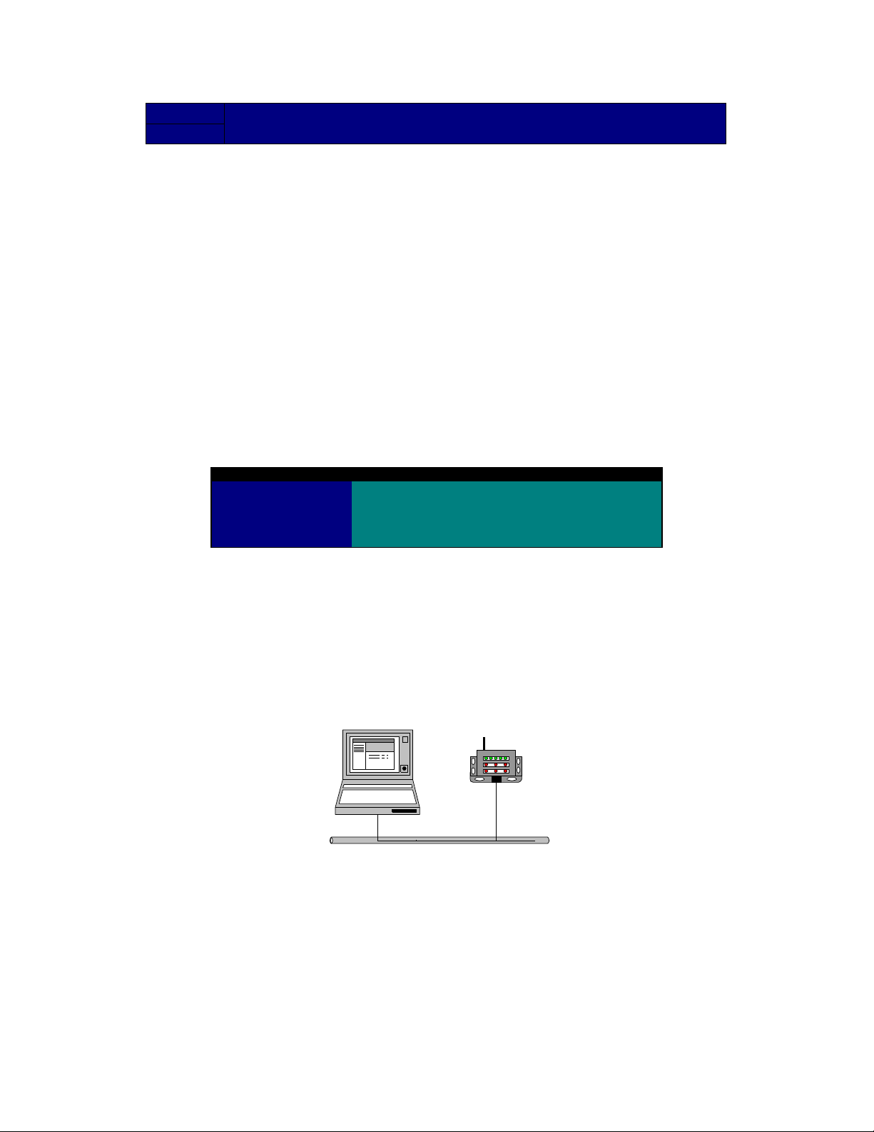
Configuration can be accomplished through a local connection or remotely over the air. A
local or direct connection is when an EZCom-IP radio is connected to the local area
network where you have the Grayhill EZCom-IP Explorer program running as illustrated
in Figure 1. Remote configuration can be accomplished over the air provided that the
remote EZCom-IP radio is already set to operate at the same center frequency as the
local radio. Remote configuration is discussed in detail in the Technical Reference
section of this manual.
Figure 1, Local Connection
EZCom
EZCom-IP Explorer Introduction
Before we start on the examples in this section let’s take a few minutes to familiarize
ourselves with the EZCom-IP Explorer program. If you have not loaded the GH EZComIP Explorer program please do so now. The Explorer is a client side program that can be
run on any 32 bit Windows based PC. It is designed to communicate configuration and
diagnostic information with the EZCom-IP radios either directly attached or via the local
area network. The program offers the user a verity of configuration and diagnostic tools.
Figure 2, below illustrates the initial screen of the Explorer program. The screen is
divided into three main parts;
Page 4 Of 54
Page 5

Network
View
Control
Grayhill EZCom IP Users Manual Rev A6 1/26/2001
1. The Network View, which graphically displays the EZCom-IP, radios in the
network.
2. The Control Tabs that can be used to change configuration settings and initiate
diagnostic functions.
3. The Monitor, which can be used to observe specific communication events.
When you first start the Grayhill EZCom-IP Explorer your will see a single icon in the
Network View. This icon represents the computer that is running the GH Explorer
program. No other icons appear at this time because the Explorer program must be
prompted to go out and find any radios in the network first. If you click on the Tools menu
and then pick Find Links the Explorer will go out and find any EZCom-IP radios on the
local network.
Figure 2, EZCom Explorer Window
Tabs
GH Explorer will then add a radio icon to the Network View for each radio it finds on the
local network (see Figure 4).
The information in the Control Tab window is associated with the icon selected in the
Network View. As you click on different icons in the Network View the information in the
Control Tab View is updated with the setup values from the object represented by the
icon selected. If you select the GH Explorer icon at the top of the window (which is
selected by default when you start the program) only the IP address tab is accessible.
This is because the GH Explorer icon points to the PC that the program is running on and
not to a radio. When you select a radio icon in the Network View the information in the
Control Tab will be downloaded from the radio and displayed in the appropriate tab. If you
changing any of the information in the Control Tab and click the update button the setup
information in the radio pointed to by the icon in the Network View will be changed
accordingly.
As you can see changing the setup information in a radio is as simple as selecting which
radio you want to modify from the Network View and then entering the appropriate
information in the Control Tab view.
Monitor
Page 5 Of 54
Page 6
Grayhill EZCom IP Users Manual Rev A6 1/26/2001
Point-to-Point Link Example
In this first example we will set up a point-to-point link between two Ethernet networks.
For simplicity we have represented both networks as consisting of one PC and one
EZCom-IP radio (router). In reality a point-to-point configuration could be used to connect
anything from a single PC and router to a fully developed enterprise network. After we
have set up the example we will uses some of the built-in EZCom diagnostic tools to test
our setup. After we complete our testing we will try a few simple client server applications
that are part of the windows operating system to demonstrate the functionality of the
network.
You will need 2 PCs and 2 EZCom-IP radios to fully implement this first example. You
may also need to have your operating system CD handy in the event that Windows wants
to copy additional files. If you don’t have 2 PCs you can still set up the example with only
one PC but you will only be able to run the built in diagnostic functions of the EZCom-IP
radio you will not be able to run the applications.
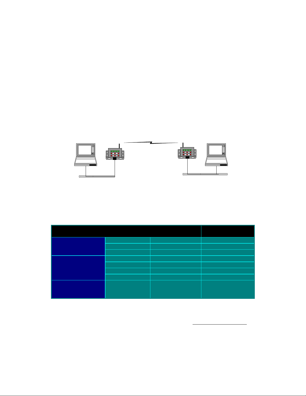
Figure 3, Point-to-Point Link
192.168.1.2
192.168.1.0
Ethernet
192.168.1.1
192.168.2.1
192.168.2.2
Ethernet
192.168.2.0
There are 3 basic steps involved in setting up this example: setting the IP addresses on
the two PCs, configuring the radios, and setting file share permissions on one of the PCs
to allow file access across the network. Table 2 shows each step along with the
parameters that need to be setup and the appropriate values.
Table 2, Point-To-Point Setup Parameters
Step Parameter Value For PC (A) &
1. Set PC IP
Addresses
Radio (A)
IP Address 192.168.1.2 192.168.2.2
Subnet Mask 255.255.255.0 255.255.255.0
Value For PC (B) &
Radio (B)
Default Gateway 192.168.1.1 192.168.2.1
2. Set Radio
Parameters
IP Address 192.168.1.1 192.168.2.1
Subnet Mask 255.255.255.0 255.255.255.0
Default Gateway 192.168.2.1 192.168.1.1
Routing Table Default Default
3. Set File Share
Permissions
File and Print sharing
for Microsoft
Networks installed
Both PCs must have an Ethernet network interface card or equivalent PCMCIA card
installed and both PCs must also have the TCP/IP protocol installed. For information on
installing your network interface card see the card manufactures installation instructions.
For help installing the TCP/IP protocol, please see the sidebar Windows TCP/IP Set Up
on page 13 of this manual.
To get started with this example take a RJ45 Category 5 patch cable and connect one
end of it to the Ethernet port on your EZCom-IP radio and connect the other end to an
open port on your network hub. If you do not have an existing network you can connect
directly to the PC’s NIC card or PCMCIA card. Now apply power to the EZCom-IP radio
Page 6 Of 54
Page 7

Grayhill EZCom IP Users Manual Rev A6 1/26/2001
and the PC. After the PC and radio have gone through their normal boot process you
should see a green link indicator (see Figure 20, on page 43). If you do not see the green
link indicator please follow the steps in the troubleshooting guide for “No Ethernet Link”.
Now that we have a physical connection between the client PC that will be running the
EZCom-IP Explorer and an EZCom-IP radio we can begin to setup our first example.
Setting-up The PC’s IP Address
1. Click the Start button. Choose Settings, Then
Control Panel.
2. Double-click the Network icon. Your Network
window should pop up as shown on the right.
3. Select the Configuration tab.
4. Highlight TCP/IP (for your network adaptor)
under the list of components installed.
5. Click the Properties Button. You should now
see the TCP/IP properties window below.
6. Select the IP Address tab.
7. Make sure the Specify IP Address option is
selected.
8. Enter the appropriate IP Address and Subnet Mask (from the setup table on page 6)
in the spaces provided.
9. Now select the Gateway tab
10. Enter the Default Gateway (again from the setup
table) and make sure you click the ADD button.
11. Click the OK button on the TCP/IP Properties
Window.
12. Click the OK button
on the Network
Window.
After clicking the OK
button on the TCP/IP
properties tab you will
be prompted to reboot
your computer before
theses changes will take effect. Click OK.
The IP Address, Subnet Mask and Default Gateway are
now set up on your PC. Repeat these steps using the
appropriate setup values for the second PC in the
network. You may wish to reopen either one of the
properties windows to verify the values match those listed in the example’s setup table.
In the next step we will setup the radio parameters for the EZCom-IP radios that will be
used in this example.
Setting-up The Radio Parameters
Start the Grayhill EZCom-IP Explorer by selecting “EZCom-IP Explorer” from your PC’s
Start/Programs menu. After the program loads select Find Links from the Tools menu at
the top of the explorer main screen. The Searching for Radios dialog box will appear.
Page 7 Of 54
Page 8

Explorer
Icon
EZCom-IP
Radio
Grayhill EZCom IP Users Manual Rev A6 1/26/2001
Once the searching process is complete press OK to return to the EZCom-IP Explorer
main window.
Figure 4, EZCom-IP Explorer After Finding a Radio
The Explorer should now look like the one shown in Figure 4, above. Don’t worry if the IP
addresses and other data on your screen are not exactly as shown. What is important is
that there is an EZCom-IP radio icon below the GH Explorer icon in the Network View.
Click on the radio icon. The data in the Control Tab window will update to reflect the
current settings for the radio you just selected. If the radio you are using is new the
settings should look like those listed in Table 1, Factory Default Settings on page 4.
The first Control Tab is the IP Address Tab, which is shown in Figure 5. On this tab we
will set the radio’s IP Address, Subnet Mask and Default Gateway. In each of the
respective text boxes please enter the appropriate setting from Table 2, Point-To-Point
Setup Parameters on page 6. When you are done your IP Address tab should look like
the one shown in Figure 5 below.
Figure 5, IP Address Tab
Page 8 Of 54
Page 9
Grayhill EZCom IP Users Manual Rev A6 1/26/2001
Don’t worry if you do not fully understand each of the settings that you are about to enter,
we will cover each of the settings in more detail in the technical reference section latter in
this manual.
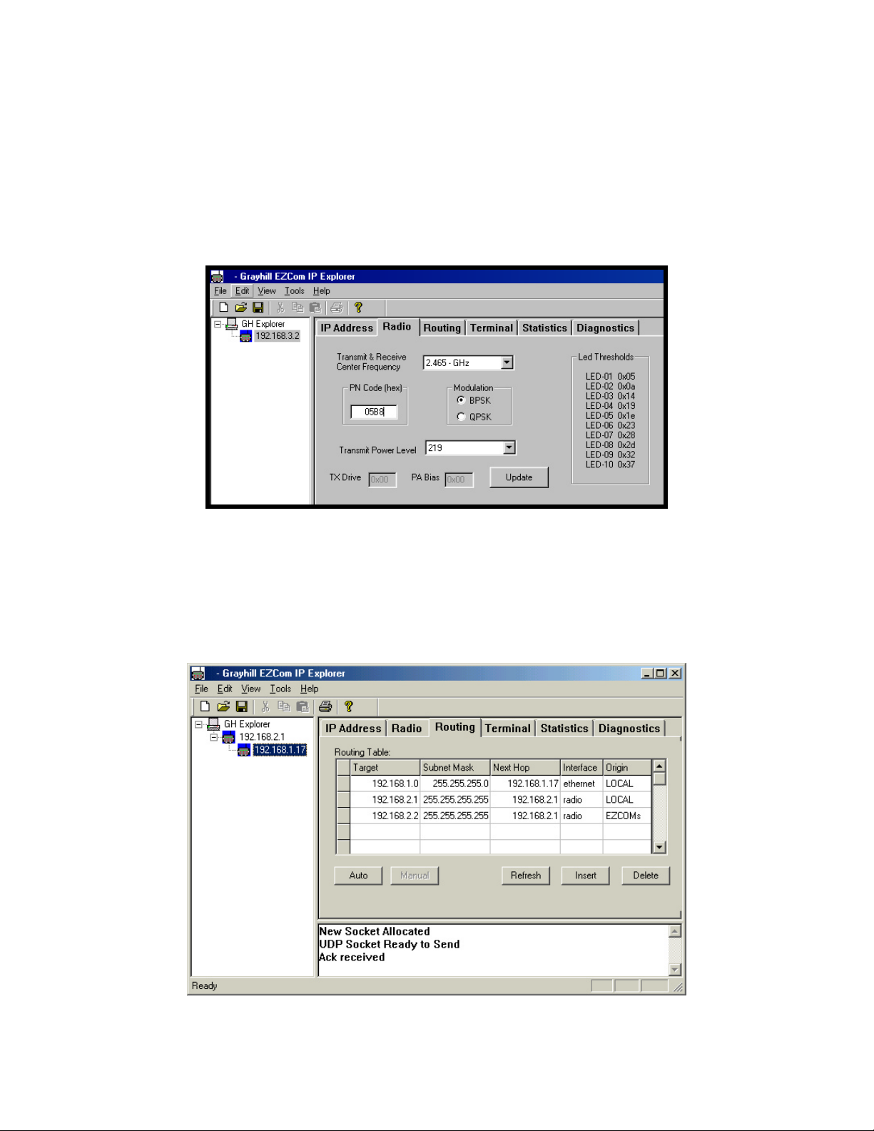
Now click the Radio Tab. You should not have to change any settings on this tab. All of
the factory defaults settings should be fine. You may just want to look over the values
and verify that they match those shown if Figure 6. If any of your values are different
please change them to match.
Figure 6, Radio Settings Tab
Now click the Routing Tab. The routing table should contain two entries, which were
created automatically by the Explorer program. For our example all routing is actually
handled by the Default Gateway setting that we established on the IP Address Tab. If
there is any other entries in your routing table select them by clicking any where on the
row and then click the Delete button. Repeat this step for all extra entries. Your routing
table should look like the one shown in Figure 7 below.
Figure 7, EZCom-IP Routing Table
Page 9 Of 54
Page 10

Grayhill EZCom IP Users Manual Rev A6 1/26/2001
Setting Up The Second PC & Radio
Now that we have completed setting up our first PC and an EZCom-IP radio we will need
to repeat the steps we followed with the second PC and radio. For the second PC and
radio use the setup information listed in the last column of Table 2 on page 6.
Testing The Radio Link
With both PCs and both radios setup we can now run a few diagnostic test to verify that
we first have a link between the radios and then a network connection from one PC to the
other. First connect the radios and PCs as shown in Figure 3. Make sure that you
connect the radios to the PC with the same subnet ID.
The first test that we will conduct will be a link test. This is to verify that the radios can
communicate. This is strictly a radio communications test and none of the network
settings are used. Select the Diagnostics Tab then click on the Link Test button. The link
test dialog box will appear. Enter the Mac Address of the radio you want to link to and
click on the Run Test button.
Figure 8, Diagnostics Tab
In the Test Results window you will see an announcement that the test is in progress.
During a link test packets are transmitted every 50 milliseconds. If you multiply the
Number of packets by this interval you can get an idea of how long the test will take.
Using the default number of packets the test should take 100*0.05 or just over a half
second.
Page 10 Of 54
Page 11

Grayhill EZCom IP Users Manual Rev A6 1/26/2001
Figure 9, Link Test Dialog
When the Link test is complete you should see the test results in the Link Test dialog
similar to the results shown in Figure 9. If your Link Test fails, that is you don’t get a large
number of Successful packets (typically 90% to 100%), please follow the steps listed in
the Troubleshooting guide on page 50.
After successfully running a link test we will now verify that we have a logical network
connection from one PC to the other. To accomplish this we will use one of the Windows
built in network utilities known as “Ping”. Actually ping is a member of the TCP/IP protocol
suite.
Ping is a simple but very useful utility program, ping sends a special (ICMP) test packet
to a designated IP address and then listens for the packet to be echoed back.
Figure 10 shows the output of a ping request. To run the Ping utility program click Start
then select Programs and click on the MS-DOS Prompt. When the DOS Window opens
type the word ping along with the IP address of the host that you want to ping and press
enter. Ping will then transmit 4 test packets and output the round trip time it takes for
each packet to traverse the network. If you are unable to successfully ping the remote PC
in this example please follow the trouble shooting procedures on page 51 for “Ping Failed
to Respond”.
Figure 10, Ping Utility Program
If you have successfully run the link test and ping test you are ready to setup your
application to run across the wireless network.
Running our example application
Before we can run an application across the wireless link we must first install the File and
Pint sharing for Microsoft Networks service. This service is built in to the Microsoft
Page 11 Of 54
Page 12

Grayhill EZCom IP Users Manual Rev A6 1/26/2001
Windows operating system and in essence enables the PC it’s running on to act as a file
and/or print server.
To enable file and printer sharing on your computer
1. Click on the Start Button and select Settings and Control Panel.
2. After the Control Panel dialog box opens double-click the Network icon.
3. Click File and Print Sharing.
4. Select the check box for the “I want to give others access to my files”, sharing
option. A check mark indicates the feature is activated.
5. Click OK.
6. Windows will now install the File & Print Sharing service on your PC. You will be
prompted that you must restart your computer before these changes will take
effect. Click OK,
After your computer reboots you will need to tell windows which files or folders you want
to share on the network. For this example we are going to simply share the entire C drive.
To share The C Drive
1. In Windows Explorer or My Computer, click the C drive root folder.
2. On the File menu, click Properties.
3. Click the Sharing tab, and then click Shared As. Enter the share name “Server
Drive”. Note: The Sharing tab is not visible if you don’t have file and print sharing
services enabled.
4. Click the Access Type you want, and, if necessary, enter a password.
Running Our Example Application
Now that we have File and Print sharing setup on our 192.168.2.2 PC we will access the
files on this machine from our 192.168.1.2 PC, which is at the other end of our wireless
link. The first thing we need to do is to make the Windows operating system on
192.168.1.2 aware of the network connection to 192.168.2.2. Start by:
1. Double clicking the My Computer icon on your windows desktop.
2. After the My Computer dialog opens, in the Address Bar type \\192.168.2.2\.
3. Just below the address bar you will see a dropdown list with the share name
“Server Drive”. This is the share name we gave to the c drive on 192.168.1.2.
Select the Server Drive share name by clicking on it.
4. The My Computer window should now be a listing of the files and folders on the
192.168.2.2 c drive. Now click on the Favorites menu and select Add to
Favorites.
You can now use the Server Drive just as though it was a hard drive in your 192.168.1.2
PC. Try by copying or accessing any of your data files just as you would if there were on
you c drive.
Page 12 Of 54
Page 13
Grayhill EZCom IP Users Manual Rev A6 1/26/2001
Windows TCP/IP Set Up
Follow these instructions to install the TCP/IP protocol on your PC only after a network
card has been successfully installed. These instructions are for Windows 95 and
Windows 98. For TCP/IP setup under Windows NT or Windows 2000, please refer to
your operating system manual.
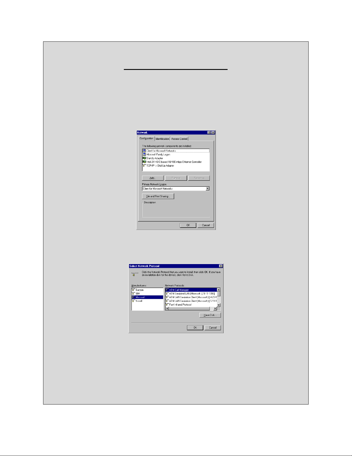
1. Click the Start button. Choose Settings, then Control Panel.
2. Double-click the Network icon. Your Network window should pop up. Select the
Configuration tab.
3. Click the Add button.
4. Double-click Protocol.
5. Highlight Microsoft under the list of manufactures.
6. Find and double-click TCP/IP in the list to the right.
7. After a few seconds you should be brought back to the main Network window. The
TCP/IP Protocol should now be listed.
8. Click OK. Windows may ask for the original Windows installation files. Supply them
as needed (i.e.: D:\win98, D:\win95, C:\windows\options\abs.)
9. Windows will ask you to restart the PC. Click Yes.
The TCP/IP Installation is complete.
Page 13 Of 54
Page 14
Grayhill EZCom IP Users Manual Rev A6 1/26/2001
Multipoint Store-&-Forward Example
This second example is designed to demonstrate in detail how to setup and utilize the
routing functions available within a TCP/IP network using the EZCom-IP radio. It may not
be practical to setup this example because it requires at least 4 EZCom-IP radios, 4 PCs,
and a WAND router. Even if you do not setup the example it is beneficial to follow along
to develop an understanding of how to setup the different routing aspects of the network.
In our first example we relied on the default Gateway settings for both the PCs and the
EZCom-IP radio to handle all of the routing decisions. No routing table entries were
made. In this example we will endeavor to more fully illustrate the routing capabilities of
the EZCom-IP radio.
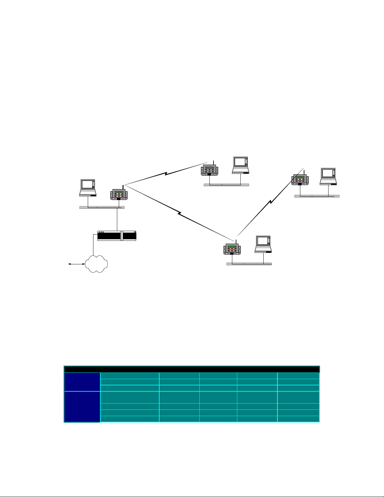
Figure 11, Example II Network layout
Ethernet
192.168. 2. 0
Ethernet
192.168. 1. 0
Ethernet
192.168. 4. 0
Router
Internet
Ethernet
192.168. 3. 0
The first step in setting up this example is to program the IP address and other settings in
the EZCom-IP radios. Probably the easiest way to handle this task is to take one PC,
which has the EZCom-IP Explorer program installed on it and directly connecting it to
each of the radios one after the other. For information and instructions on how to perform
the setup tasks from a single point in the network please refer to EZCom-IP Explore
documentation on page 44. Table 3, below is a listing of all the settings for both the IP
Address Tab and the Radio Tab that need to be set up. Most of these settings are the
factory default settings and should already be set.
Table 3, Example II, EZCom-IP Radio Settings
Tab Setting Radio A Radio B Radio C Radio D
IP Address
Radio
* Indicates Factory Default Settings
IP Address 192.168.1.2 192.168.2.2 192.168.3.2 192.168.4.2
Default Gateway 192.168.1.3 192.168.1.2 192.168.1.2 192.168.3.2
Subnet Mask 255.255.255.0 25.255.255.0 255.255.255.0 255.255.255.0
* TX & RX Center
Frequency
* PN Code (Hex) 05B8 05B8 05B8 05B8
* Modulation BPSK BPSK BPSK BPSK
* Transmit Att. level 0 dB 0 dB 0 dB 0 dB
2.441-GHz 2.441-GHz 2.441-GHz 2.441-GHz
Once we have the radio settings complete we will need to setup the TCP/IP proprieties
for the remaining devices on the four separate subnets. For this example all four subnets
Page 14 Of 54
Page 15

Grayhill EZCom IP Users Manual Rev A6 1/26/2001
are part of the same network. The IP style network ID is 192.168.0.0 with a subnet mask
of 255.255.255.0. Therefore the third byte of the IP address is the subnet ID. The
individual subnets are simply identified as (.1), (.2), (.3) & (.4). All of the devices on all
four subnets have the same subnet mask 255.255.255.0.
The IP addresses for each of the devices in the network are listed in Table 4 below. If you
need help setting the IP addresses on the PCs please refer to Setting-up The PC’s IP
Address in the first example on page 4. If you need help setting up the IP address of your
router please refer to the manufactures instructions.
Table 4, Example II Device IP Addresses
Subnet PC EZCom-IP
Router
Radio
(.1) 192.168.1.1 192.168.1.2 192.168.1.3
(.2) 192.168.2.1 192.168.2.2 NA
(.3) 192.168.3.1 192.168.3.2 NA
(.4) 192.168.4.1 192.168.4.2 NA
Next we need to establish the routing tables for each of the devices in the network.
Before we jump into entering routing table information lets take a moment or two and
discuss the routing requirements. If you are uncertain as to what we mean when we are
talking about routing tables and default gateways you can refer to EZCom IP Routing on
page 40 of this manual.
Subnet (.1) consists of three devices: a PC, a router and an EZCom-IP radio. One port on
the router is connected to our subnet and another is connected to the Internet. The
primary purpose of the router is to allow Internet access to all of the PCs in our network.
Therefore all of the other subnets need to be able to communicate with subnet (.1).
Subnet (.4) as shown in Figure 11, is only able to communicate with subnet (.3) therefore
we will need to route subnet (.4) traffic through subnet (.3).
Subnet (.2) can only communicate with subnet (.1) therefore we will have to route any
traffic from subnet (.2) to either subnet (.3) or subnet (.4) through subnet (.1).
Since subnet (.2) can only communicate with subnet (.1) we can set the default gateway
on subnet (.2)’s EZCom-IP radio to 192.168.1.2. This will cause the radio to forward all
packets that are not specifically targeted for devices on subnet (.2) to subnet (.1). In
addition to setting the radio’s default gateway we also need to set subnet (2)’s PC default
gateway to 192.168.2.2. This will direct all datagrams that are not destine for a subnet
(.2) device to the radio.
The setup for devices on subnet (.4) are similar to what we just described for subnet (.2).
First we need to set the default gateway on the PC to 192.168.4.2 this will direct all data
traffic not intended for a device on subnet (.4) to the radio for transmission. Next we need
to set the default gateway of the radio to 192.168.3.2. This indicates to the radio that all
datagrams arriving from the network should be transmitted to the radio on subnet (.3).
The settings for subnet (.3) are slightly different than subnets (.2) & (.4) because the
radio on subnet (.3) can communicate with both subnet (.1) and (.4). First we will set the
default gateway on the PC to 192.168.3.2 thus all datagrams not intended for subnet (.3)
will be forwarded to the radio for transmission. Next we will have to set the default
gateway on the radio to 192.168.1.2 this will handle the bulk of the traffic assuming there
is a lot of Internet activity. In addition to the default gateway setting we will also need to
add a route to the routing table in the radio to forward subnet (.4) packets to the radio on
(.4). Add the following route: (Destination 192.168.4.0, Subnet Mask 255.255.255.0, Next
Hop 192.168.4.2). Please refer to the Routing Tab section on page 47 of this manual for
specific instructions on how to enter a route in the radios routing table.
Page 15 Of 54
Page 16
Grayhill EZCom IP Users Manual Rev A6 1/26/2001
Now for subnet (.1), first we will need to set both the PC’s and radio’s default gateways to
192.168.1.3. This will insure that all packets not specifically addressed to one of our
subnets be forwarded to the Internet router. Next we need to add routes to the radio’s
routing table for all packets destined for one of our subnets. This will entail entering three
separate routes as shown in Table 5 below.
Table 5, Routing Table for 192.168.1.2 (EZCom-IP radio)
Destination Subnet Mask Next Hope Interface Origin
192.168.2.0 255.255.255.0 192.168.2.2 Radio EZCom
192.168.3.0 255.255.255.0 192.168.3.2 Radio EZCom
192.168.4.0 255.255.255.0 192.168.3.2 Radio EZCom
We will also need to add the following routes to the subnet (.1) PC’s routing table and to
the Internet routers routing table as well. If you are not familiar with the adding a route to
your PC’s routing table please refer to the sidebar “
The ROUTE Utility Program” on page 31 of this manual. For adding routes to your router
please refer to the manufactures instructions.
Table 6, Routing Table for 192.168.1.1 (PC)
Destination Subnet Mask Next Hope Interface
192.168.2.0 255.255.255.0 192.168.1.2
192.168.3.0 255.255.255.0 192.168.1.2
192.168.4.0 255.255.255.0 192.168.1.2
These PC routes were added to direct any datagrams generated by the PC destine for
one of our subnets to the radio for transmission. This is necessary because we have
already set the default gateway at the PC to 192.168.1.3, which is the Internet router. On
all of our other subnets we did not need to make individual route entries because any
datagrams that needed to be routed outside the local subnet where handled by the
default gateway entry. Subnet (.1) on the other hand has two routers, the Internet router
and the EZCom-IP radio.
In summary to setup the network illustrated in Figure 11 on page 14 you would first need
to set each device IP address as listed in Table 4 and then you would have to establish
the routing tables which are summarized in Table 7.
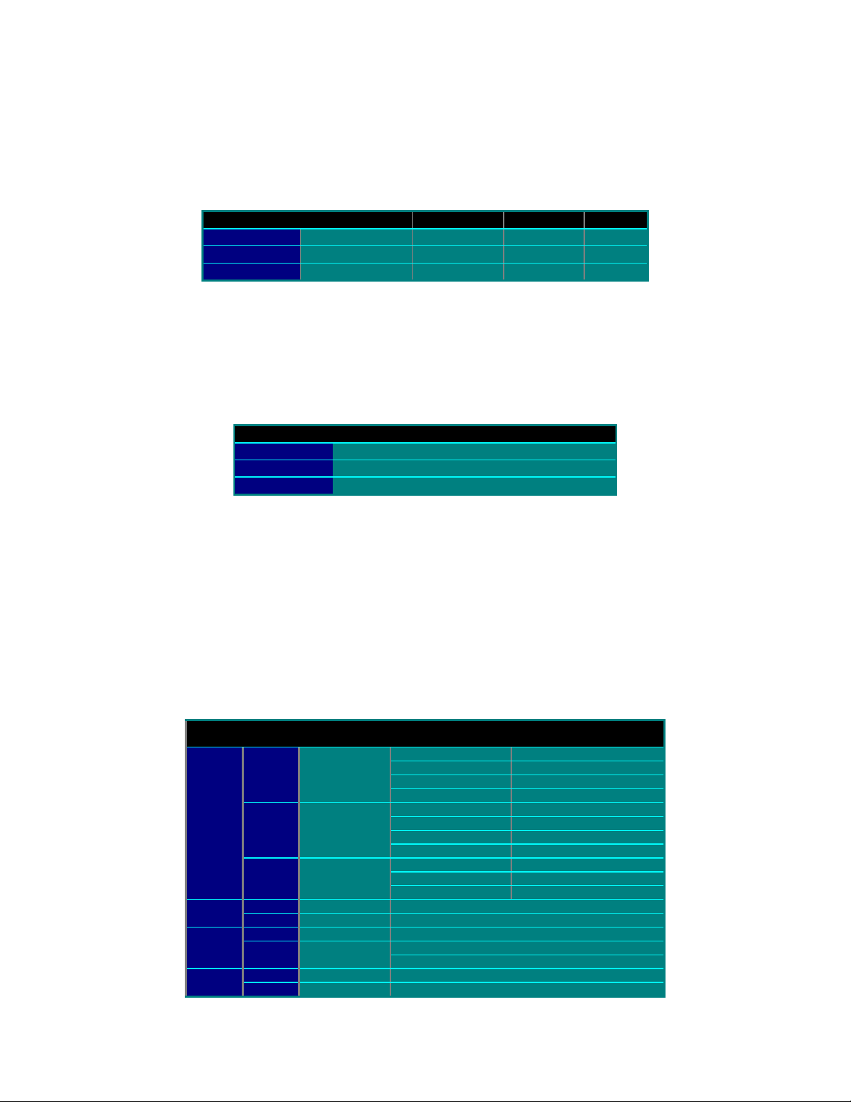
Table 7 Store & Forward Example Routing Summary
Subnet Device Device IP
(.1)
(.3)
PC 192.168.1.1
Radio 192.168.1.2
Router 192.168.1.3
PC 192.168.2.1 Default Gateway 0.0.0.0 192.168.2.2(.2)
Radio 192.168.2.2 Default Gateway 0.0.0.0 192.168.1.2
PC 192.168.3.1 Default Gateway 0.0.0.0 192.168.1.2
Radio 192.168.3.2
PC 192.168.4.1 Default Gateway 0.0.0.0 192.168.4.2(.4)
Radio 192.168.4.2 Default Gateway 0.0.0.0 192.168.3.2
Address
Route Type Target Next Hop
Default Gateway 0.0.0.0 192.168.1.3
Add Route 192.168.2.0 192.168.1.2
Add Route 192.168.3.0 192.168.1.2
Add Route 192.168.4.0 192.168.1.2
Default Gateway 0.0.0.0 192.168.1.3
Add Route 192.168.2.0 192.168.2.2
Add Route 192.168.3.0 192.168.3.2
Add Route 192.168.4.0 193.168.3.2
Add Route 192.168.2.0 192.168.1.2
Add Route 192.168.3.0 192.168.1.2
Add Route 192.168.4.0 192.168.1.2
Default Gateway 0.0.0.0 192.168.1.2
Add Route 192.168.4.0 192.168.4.2
Page 16 Of 54
Page 17

Grayhill EZCom IP Users Manual Rev A6 1/26/2001
Page 17 Of 54
Page 18

Grayhill EZCom IP Users Manual Rev A6 1/26/2001
Section
2.
Technical Reference
Introduction
The technical reference section of this manual is intended to develop a basic overview on
the subject of network technology, sufficient in detail to explain the routing function of the
EZCom-IP radio. It is not intended to be an exhaustive coverage of the subject but it dose
burrow in to some detail of the lower level protocols. Although much of what is presented
is germane to all forms of network communications, the examples and illustrations are
biased toward Ethernet IP applications because it is the underling technology of the
EZCom-IP radio.
Many of the subsections that follow are relatively generic in nature and may seem
remedial to some readers. The following list describes each section and presents
recommendations as to who should read those sections and who can feel free to skip
them to focus on the EZCom-IP specific information.
1. Protocols And Protocol Architecture starts off with a basic introduction to the
concept of a protocol stack it then moves on to a general description of the
Internet Protocol. If you are already familiar with the idea of a protocol stack you
can skip right to the descriptions of the IP protocol. If you are already familiar with
the IP protocol also. please feel free to skip this section entirely.
2. TCP/IP Communications presents an overview of the TCP/IP protocol stack
with a detailed description of the IP protocol. The section is divided into four
subsections: The Application Layer, The Transport Layer, The Network Layer
and The Physical Layer. Having a through understanding of the TCP/IP protocol
is not necessary for the application of the EZCom-IP radio. This section is
presented for the advanced user. If you are in a hurry you may want to just read
the network layer subsection.
3. Subnetting. This is a fairly lengthy section that goes into some detail regarding
why and how to subnet. Subnetting is one of the more important topics dealt with
in this manual. A good understanding of the subject matter will greatly improve
your ability to establish large distributed wide area networks. Any one not already
familiar with Subnetting and considering using the EZCom-IP radio in a largescale distributed network should read this material.
4. EZCom IP Routing - This section briefly goes through the EZCom-IP routing
mechanism. Its brevity is primarily due to the simplistic nature of the routing
scheme. Anybody who wants to gain even an intuitive understanding of the
EZCom-IP radio should read this section. It will help you maximize the
functionality of an EZCom-IP extended network.
5. Connectors and Indicators. Briefly introduces you to the indicators on the face
of the radio.
6. EZCom-IP Explorer program This section goes through all if the menu picks
and program dialogs explaining where specific information is entered and where
appropriate also offers some guidance as to what should be entered.
Page 18 Of 54
Page 19

Grayhill EZCom IP Users Manual Rev A6 1/26/2001
Protocols And Protocol Architecture
When computers and/or other data processing devices such as PLC’s exchange data,
there must be a data path between the two computers, via a communication network.
Although, a data path alone is not sufficient to establish communications, more is
needed. Typically the following tasks also need to be performed:
1. The source system must inform the communication network of the identity of the
desired destination system.
2. The source system must ascertain that the destination system is prepared to
receive data.
3. The application on the source system must ascertain that an application on the
destination system is prepared to accept the data for a particular use.
4. If the data formats used on the two systems are incompatible, one or the other
system must perform a format translation function.
It is clear that there must be a high degree of cooperation between the two computer
systems. The exchange of information between computers for the purpose of cooperative
action is generally referred to as data communications. Similarly, when two or more
computers are interconnected via a communication network, the set of computer stations
are referred to as a computer network.
In this discussion of computer networks, two concepts are paramount, Protocols and
Protocol Architectures.
A protocol is used for communication between entities in different systems. The terms
"entity" and "system" are used in a very general sense. Examples of entities are user
application programs, file transfer packages, database management systems, electronic
mail facilities, etc. Examples of systems are computers, PLCs, and remote sensors.
In general, an entity is anything capable of sending or receiving information, and a
system is a physically distinct object that contains one or more entities. For two entities to
communicate successfully, they must "speak the same language." What is
communicated, how it is communicated, and when it is communicated must conform to
some mutually acceptable conventions between the entities involved. The conventions
are referred to as a protocol, which may be defined as a set of rules governing the
exchange of data between two entities. The key elements of a protocol are
• Syntax, which includes such things as data format and signal levels.
• Semantics, which includes control information for coordination and error
handling.
• Timing, which includes speed matching, and sequencing.
Having introduced the concept of a protocol, we can now introduce the concept of
protocol architecture. It is clear that there must be a high degree of cooperation between
the two computers. Instead of implementing the logic for this as a single module, the task
is broken up into subtasks, each of which is implemented separately. Thus, instead of a
single module for performing communications, there is a structured set of modules that
implements the communications function. That structure is referred to as a protocol
architecture or protocol stack. In the remainder of this section, we will present a simplified
protocol architecture. Followed by an introduction to the more complex TCP/IP protocol
stack.
Page 19 Of 54
Page 20

Grayhill EZCom IP Users Manual Rev A6 1/26/2001
A Simple Model
In very general terms, data communications can be said to involve three agents:
applications, computers, and networks. The applications execute on computers that can
often support multiple simultaneous applications. The computers are connected to the
network, and the data to be exchanged is transferred by the network from one computer
to another. Thus, the transfer of data from one application to another involves first getting
the data to the computer in which the application resides and then getting it to the
intended application within the computer.
With this concept in mind, it appears natural to organize the communication task into
three relatively independent layers:
• Application layer
• Transport layer
• Network access layer
The network access layer is concerned with the exchange of data between a computer
and the network to which it is attached. The sending computer must provide the network
with the address of the destination computer, so that the network may route the data to
the appropriate destination. Thus, it makes sense to separate those functions having to
do with network access into a separate layer.
Regardless of the nature of the applications that are exchanging data, there is usually a
requirement that data be exchanged reliably. That is, we would like to be assured that all
of the data arrive at the destination application and that the data arrive in the same order
in which they were sent. As we shall see, the mechanisms for providing reliability are
essentially independent of the nature of the applications. Thus, it makes sense to collect
those mechanisms in a common layer shared by all applications; this is referred to as the
transport layer.
Finally, the application layer contains the logic needed to support the various
applications. For each different type of application, such as file transfer program, a
separate module is needed that is peculiar to that application.
To demonstrate this concept let us trace a simple operation. Suppose that an application,
on computer A, wishes to send a
message to another application, on
computer B. The application on A
hands the message over to its
transport layer with instructions to send
Computer
A
Application
Computer
B
Application
it to a specific application on computer
B. The transport layer hands the
Transport
Transport
message over to the network access
layer, which instructs the network to
Network
Network
send the message to computer B. Note
that the network need not be told the
identity of the destination application.
Phyical Layer
All that it needs to know is that the data
is intended for computer B.
To control this operation, control information, as well as the original user data, must be
transmitted. Let us say that the sending application generates a block of data and passes
this to the transport layer. The transport layer may break this block into two smaller
pieces to make it more manageable. To each of these pieces the transport layer appends
a transport header, containing protocol control information. The combination of data and
control information is known as a protocol data unit (PDU); in this case, it is referred to as
a transport protocol data unit. The header in each transport PDU contains control
Page 20 Of 54
Page 21

Grayhill EZCom IP Users Manual Rev A6 1/26/2001
information to be used by the peer transport protocol at computer B. Examples of items
that may be stored in this header include
• Destination application. When the destination transport layer receives the
transport protocol data unit, it must know to whom the data are to be delivered.
• Sequence number. Because the transport protocol is sending a sequence of
protocol data units, it numbers them sequentially so that if they arrive out of
order, the destination transport entity may reorder them.
• Error-detection code. The sending transport entity may include a code that is a
function of the contents of the remainder of the PDU. The receiving transport
protocol performs the same calculation and compares the result with the
incoming code. A discrepancy results if there has been some error in
transmission. In that case, the receiver can discard the PDU and take corrective
action.
The next step is for the transport layer to hand each protocol data unit over to the
network layer, with instructions to transmit it to the destination computer. To satisfy this
request, the network access protocol must present the data to the network with a request
for transmission. Once again, this operation requires the use of control information. In this
case, the network access protocol appends a network access header to the data it
receives from the transport layer, creating a network access PDU. Examples of the items
that may be stored in the header include
• Destination computer address. The network must know to whom (which
computer on the network) the data are to be delivered.
• Facilities requests. The network access protocol might want the network to make
use of certain facilities, such as priority.
With the concept of protocol architecture still fresh in our minds let jump right into the
TCP/IP protocol stack because it is this architecture that the EZCom-IP radio supports.
The TCP/IP Protocol Architecture
TCP/IP is the most widely used interoperable network communications architecture in
use today. TCP/IP is a result of protocol research and development conducted on the
experimental packet-switched network, ARPANET, funded by the Defense Advanced
Research Projects Agency (DARPA), and is generally referred to as the TCP/IP protocol
suite. This protocol suite consists of a large collection of protocols that have been issued
as Internet standards by the Internet Activities Board (IAB).
There is no official TCP/IP protocol model, however, based on the protocol standards that
have been developed, we can organize the communication task for TCP/IP into five
relatively independent layers:
1. Application layer
2. Host-to-host, or Transport layer
3. Internet layer
4. Network access layer
5. Physical layer
The physical layer covers the physical interface between a data transmission device
(e.g., computer or PLC) and a transmission medium or network. This layer is concerned
with specifying the characteristics of the transmission medium, the nature of the signals,
the data rate, and related matters.
The network access layer is concerned with the exchange of data between an end
system and the network to which it is attached. The sending computer must provide the
Page 21 Of 54
Page 22

Grayhill EZCom IP Users Manual Rev A6 1/26/2001
network with the address of the destination computer, so that the network may route the
data to the appropriate destination.
The network access layer is concerned with access to and routing data across a network
for two end systems attached to the same network. In those cases where two devices are
attached to different networks, procedures are needed to allow data to traverse multiple
interconnected networks. This is the function of the Internet layer. The Internet protocol
(IP) is used at this layer to provide the routing function across multiple networks. This
protocol is implemented not only in the end systems but also in routers. A router is a
processor that connects two networks and whose primary function is to relay data from
one network to the other on its route from the source to the destination end system. This
is essentially what the EZCom IP radio dose.
Regardless of the nature of the applications that are exchanging data, there is usually a
requirement that data be exchanged reliably. That is, we would like to be assured that all
of the data arrive at the destination application and that the data arrive in the same order
in which they were sent. The mechanism for providing this reliability is referred to as the
host-to-host layer, or transport layer. The Transmission Control Protocol (TCP) is the
most commonly used protocol to provide this functionality.
Finally, the application layer contains the logic needed to support the various user
applications. For each different type of application, such as file transfer program, a
separate module is needed that is peculiar to that application.
Figure 12, TCP/IP Protocol Stack
Mac header
Application Data
TCP header
I P header
LLC header
MAC trailer
IP Datagram
MAC Frame
Application layer
TCP Layer
IP Layer
LLC Layer
Physical Layer
MAC Layer
Figure 12, shows how the TCP/IP protocols are implemented in end systems. Note that
the physical and network access layers provide interaction between the end systems and
the network, whereas the transport and application layers are what is known as end-toend protocols; they support interaction between two end systems. The Internet layer has
the flavor of both. At this layer, the end system communicates routing information to the
network but also must provide some common functions between the two end systems.
Page 22 Of 54
Page 23

Grayhill EZCom IP Users Manual Rev A6 1/26/2001
TCP/IP Communications
The TCP/IP Protocol Stack
In the previous section we introduced the concept of Protocol Architecture and we
described the basic structure of the TCP/IP protocol stack. In this section will take a
closer look at some of the individual protocols associated with the TCP/IP protocol stack.
Most of our attention will be focused on the Internet Protocol (IP) because it is
responsible for routing of information on a TCP/IP network. Essentially an EZCom-IP
radio is an IP router and as such relies on the IP protocol to implement routing function.
Application Layer
The top layer of the stack is the Application layer. This is not where you find applications
such as Word or Excel, but rather where you find NetBIOS and Winsock (the two main
networking APIs in the Microsoft network architecture). These components provide
services to the actual applications that can call on the network by using these network
APIs. As stated, the APIs provide a standard method for programmers to call on the
services of the underlying network without having to know anything about it.
Sitting at this layer, you might also add an NCP (Netware Core Protocol) component to
enable you to talk with or provide services to the Novell world, or maybe add an NFS
component to enable you to work with the Network File System that is popular on the
Unix platforms.
Transport Layer
Overview of TCP
TCP is used to provide a connection-oriented delivery service for the higher-level
protocols. To do this, TCP must first establish a session with the remote communicating
host. It does this by means of a three-way handshake. First the host initiating the
communications sends a packet to the other host that contains information about itself
and a SYN (or synchronize flag) telling the other host that a session is requested. The
other host receives this packet and responds with information about itself—the SYN flag
and an ACK (acknowledgment) of the information that it received. Finally the first host
ACKs the information it received from the other, and a session now exists between the
two systems.
At the end of the communication session, a similar three-way handshake is used to drop
the session with the remote host. This ensures that both of the hosts are through
transmitting. It closes the session cleanly.
Transmission Control Protocol (TCP)
TCP provides reliable communication between processes that run on interconnected
hosts. This Transport layer functions independently of the network structure. TCP is not
concerned with routing data through the internetwork; the network infrastructure is the
responsibility of the IP layer. TCP on one host communicates directly with TCP on
another host, regardless of whether the hosts are on the same network or remote from
each other.
In fact, TCP is oblivious to the network. A wide variety of network technologies can be
accommodated, including circuit switching and packet switching on local and wide area
networks. TCP identifies hosts by using IP addresses and does not concern itself with
physical addresses.
Page 23 Of 54
Page 24

Grayhill EZCom IP Users Manual Rev A6 1/26/2001
The main functions of TCP are:
• Session establishment
• Byte stream communications
• Sliding windows
Session Establishment
Applications using the TCP protocol must be able to open, close, and check the status of
sessions to allow them to communicate. To perform this function, TCP uses a three-way
handshake. The handshake is important not only to create the session, but also in
allowing the hosts to exchange data about their capabilities.
The handshake starts when one host is asked by Winsock to open a connection (or
session). A TCP segment is generated to start the session, and the SYN control bit is
turned on. This tells the other host that a session is requested. The host also includes in
the TCP header the starting Sequence number for this connection and the current
window size.
The TCP segment is now sent to the other host, who acknowledges the segment,
including its window size. The segment sent to acknowledge the first host also includes
the SYN control bit. Finally, the process ends when the first host acknowledges the
receipt of the other’s segment.
After the hosts have completed their communications, the connection is closed in a
similar manner, the difference being that the FIN control bit is set rather than the SYN bit.
Byte Stream Communications
When a connection (session) is established, the upper-layer protocol uses this
connection to send data to the other host. The upper-layer protocols do not concern
themselves with formatting data to fit the underlying topology, but send the data as a
continuous stream.
This process, called byte stream communications, means that TCP must have some
method for dealing with a large volume of data that has no boundaries. Every byte in a
stream is assigned a Sequence number, enabling every byte sent, to be acknowledged. If
TCP sent each byte as a single package, this would be unmanageable. TCP therefore
bundles the data stream it sends into segments; a segment contains chunks of data.
The TCP header specifies the segment Sequence number for the first byte in the data
field, and each segment also incorporates an Acknowledgment number. Because you do
not know which byte will be the first in a given segment, you must give each byte a
Sequence number. When TCP sends a segment, it retains a copy of the segment in a
queue (transmit window), where it remains until an acknowledgment is received.
Segments not acknowledged are retransmitted.
When TCP acknowledges receipt of a segment, it relieves the sending TCP of
responsibility for all data in that segment. The receiving TCP then becomes responsible
for delivering the data in the segment to the appropriate upper-layer process.
Sliding Windows
This is all necessary because of the way the Internet (or your intranet) works. The
segments that you send could each take a different route. This might happen because
routers can become busy or links could fail. Data must be buffered on the sending host
until the remote host has acknowledged it.
The Sliding Window is the buffer that enables byte stream communications, and enables
TCP to guarantee the delivery of segments of data. During the session establishment, the
two hosts exchange the current size of the receive window. This information is also
Page 24 Of 54
Page 25

Grayhill EZCom IP Users Manual Rev A6 1/26/2001
included in the TCP header of each and every segment sent. A host that is
communicating sets the size of its send window to match the other host’s receive
window.
If you look at the data being transmitted, you would see a series of bytes. If you overlay a
window at the start of the data, you can see that a portion of the data falls into the
window. This is the only data with which the TCP layer can work. The window cannot
slide (move to cover more data) until all the data currently in the window is sent and
acknowledged.
As the data in the window is transmitted to the remote host, the retransmit timer is set for
each segment sent. The receiving host acknowledges the segments when its receive
window fills to a predetermined amount (in Windows 98 & NT this is two consecutive
segments). When the sender receives the acknowledgment, it’s transmit window slides
past the acknowledged data and the next segments are transmitted.
In the process of moving the data from point A to point B, many things might happen to
the segments being transmitted. They could be lost due to congestion at the routers, or
could be received out of sequence.
If a packet is lost, the retransmit timer expires on the sending host, the segment is
retransmitted, and the retransmit timer is set to two times the original value. This
continues until the segment is acknowledged or the maximum number of retries has been
made (about 16 seconds). If the data cannot be transmitted, TCP reports the condition
and you get an error message.
In a case where the segments are received out of order, the receiving host sets the
delayed acknowledgment timer for the segment it did receive, and waits for other
segments to arrive. If the delayed acknowledgment timer (hard-coded to 200 ms) expires,
TCP on the receiving host sends an acknowledgment for the segment it did receive.
TCP Window Size
You can adjust the size of the sliding window. Great care should be taken in adjusting the
window size. If the window size is set too small, only a few packets can be sent at a time.
This means that the system transmits the packets and then must wait for
acknowledgments. If the size is set too large, network traffic delays the transmission.
You can adjust the TCP window size under:
HKEY_LOCAL_MACHINE\System\CurrentControlSet\Services\TCPIP\Paramters.
The default is 8760, which is tuned for Ethernet. This setting affects only TCP, because
UDP does not use a sliding window.
User Datagram Protocol
TCP is a connection- or session-oriented protocol that requires hosts to establish a
session, which is maintained for the duration of a transfer, after which the session is
closed. The overhead required to maintain connections is justified when reliability is
required but often proves to be misspent effort.
User Datagram Protocol provides an alternative transport for processes that do not
require reliable delivery. UDP is a datagram protocol that does not guarantee data
delivery or duplicate protection. As a datagram protocol, UDP need not be concerned
with receiving streams of data and developing segments suitable for IP. Consequently,
UDP is an uncomplicated protocol that functions with far less over-head than TCP.
In the following several situations, UDP might be preferred over TCP as a host-to-host
protocol:
Page 25 Of 54
Page 26

Grayhill EZCom IP Users Manual Rev A6 1/26/2001
• Messages that require no acknowledgment. Using UDP can reduce network
overhead. Simple Network Management Protocol (SNMP) alerts fall into this
category. On a large network, considerable SNMP alerts are generated because
every SNMP device transmits status updates. Seldom, however, is loss of an
SNMP message critical. Running SNMP over UDP, therefore, reduces network
overhead.
• Messages between hosts are sporadic. SNMP again serves as a good
example. SNMP messages are sent at irregular intervals. The overhead required
to open and close a TCP connection for each message would delay messages
and bog down performance.
• Reliability is implemented at the process level. Network File System (NFS) is
an example of a process that performs its own reliability function and runs over
UDP to enhance network performance.
Network Layer
Both TCP and UDP pass information to the IP layer. This layer is responsible for actually
moving the data from one machine on the network (or internet work) to another. The IP
layer handles a number of different communication tasks. The IP layer, however, does
not guarantee delivery; this is dealt with by TCP. Some of the functions handled at this
layer include the following:
• Routing of datagrams
• Resolution of IP addresses to MAC addresses
• Fragmentation and re-assembly of datagrams
• Error detection and reporting
With respect to the EZCom-IP radio this is the most important part of the TCP/IP stack
because this is where routing takes place. The EZCom-IP radio processes IP packets
just like a PC or other device on the network.
Before we can have a truly meaningful discussion regarding how the Network layer
performs it’s tasks we need to first develop an understanding of the IP addressing
scheme.
Overview of TCP/IP Addresses
To make TCP/IP work, each and every device on a TCP/IP network requires a unique
address. An IP address identifies the device to all the other devices on the network. IP
addresses are made up of two parts. The first identifies the network ID. This ID is used to
route the information being sent to the correct network. The other part of the IP address
is the host ID, a unique number that identifies each computer and device on your TCP/IP
network.
An IP address is very similar to your street address. If your address is 110 Main Street,
the address identifies which street you are on, Main Street. It also identifies your house
on that street, number 110. The only difference between a street address and a TCP/IP
address is that the street addresses are reversed. If this were a TCP/IP address, it would
look like this: Main Street, 110.
How much of the address describes the network ID depends on the type of address you
have. Three main classes of addresses exist: Class A, B, and C. A TCP/IP address is,
simply put, a 32-bit binary number. Looking at an address as 32 zeros or ones is difficult
for humans, so the address is viewed as a dotted decimal address in the following format:
198.53.147.153. In this case, you are on network 198.53.147, and you are host number
153. Each of the four numbers represents 8 bits of the address and is referred to as an
Page 26 Of 54
Page 27

Grayhill EZCom IP Users Manual Rev A6 1/26/2001
octet or byte. To understand TCP/IP and some of the concepts that make it work, it is
important to be familiar with the binary form of the address.
Understanding binary is relatively easy. Look at the number 238, for example. In
conventional math, this is two hundred and thirty-eight. Automatically, you see the 2 as
two groups of one hundred, the 3 as three groups of ten, and there are eight groups of
one. Each of the digits is multiplied by a positional value to make the total. That value is
always ten times the value to the right because there are ten different numbers: 0 1 2 3 4
5 6 7 8 9.
Normally, you need only to work with binary numbers that are 8 digits long. Table 8,
shows the values for those first 8 positions:
Table 8, Bit Position Values
128 64 32 16 8 4 2 1
In binary, there are only two numbers, 1 and 0. Where the decimal system is a base ten
system, the binary system is a base two system. Like the decimal system, the positional
values increase. Here, however, they increase by two times the previous value
(exponentially). Using Table 8, you should be able to figure out that the binary code
110110 does not represent one hundred and ten thousand, one hundred and ten.
Instead, it represents one group of thirty-two, one group of sixteen, no groups of eight,
one group of four, one group of two, and no groups of one. That is, 110110 represents
the number 54 if you express it in decimal form.
If you were to take the 198 from the example address 198.53.147.153, you could express
this number as 128+64+4+2 (or 11000110). Remember that each of the 4 numbers
represents 8 bits of the address, making up the total of 32 bits.
The most obvious difference between the three main types of addresses is the number of
octets used to identify the network ID. Class A uses the first octet only; this leaves 24 bits
(or three octets) to identify the host. Class B uses the first two octets to identify the
network, leaving 16 bits (two octets) for the host. Class C uses three octets for the
network ID, leaving 8 bits (one octet) for the host.
Table 9, TCP/IP Address Classes—First Octet
Class Start
(Binary)
00000001 01111111 1 127
A
10000000 10111111 128 191
B
11000000 11011111 192 223
C
Finish
(Binary)
Start
(Decimal)
Finish
(Decimal)
A couple of rules determine what you can and cannot use for addresses. Neither the
network ID nor the host ID can be represented by all 0’s or by all 1’s, because each of
these conditions has a special meaning. As well, the network with the first octet 127 is
used solely for loop back tests.
The classes of networks also differ in how their addresses start in binary. Class A
addresses start with 0. Class B addresses start with 10. Class C addresses start with
110. You can tell which class of address a host has by the first octet of its TCP/IP
address. Knowing that the first octet represents the first 8 bits of the address, and by
knowing the starting bits for the classes of addresses, you can see the first octet ranges
for the respective classes in Table 9
Page 27 Of 54
Page 28

Grayhill EZCom IP Users Manual Rev A6 1/26/2001
Figure 13, IP Address Formats
0 Network (7 bits)
10
110
Network (14 bits)
Network (21 bits)
Format undefined111
Host (24 bits)
Host (16 bits)
Host (16 bits)
Class A
Class B
Class C
Extended
Addressing Class
Because the Class A addresses use only the first octet to identify the network ID, there
are a limited number of them (126, to be exact; 127 is reserved). Each of these 126
networks, however, can have many hosts on it: 2 24 (the remaining 24 bits) hosts minus
two (the host IDs that are all 0’s and all 1’s) equals 16,777,214 hosts on a single network
(albeit impossible).
Class B addresses use the first two octets. The first 2 bits, however, are set to binary 10.
This leaves 14 bits that can be used to identify the network: 2 14 possible combinations (6
bits in the first octet and 8 from the second)—16,384 network IDs (because the first two
digits are 10, you don’t have to worry about an all 0’s or all 1’s host ID.) Each of those
network IDs has 16 bits left to identify the host or 65,534 hosts (2 16 – 2).
Class C networks use three octets (or 24 bits) to identify the network. The first three bits,
however, are always 110. This means that there are five bits in the first octet and eight in
the other two that can be used to uniquely identify the network ID or 2
networks (2,097,152)—each of which has 8 bits for hosts or 254 (2
8
–2).
21
possible
Table 10 summarizes all the possible TCP/IP addresses.
Table 10, Address Class Summary
Address
Class
First
Octet
Finish Number of
Networks
Hosts
Each
Start
A 1 126 126 16,777,214
B 128 191 16,384 65,534
C 192 223 2,097,152 254
Internet Protocol Routing
When a packet arrives at the IP layer the subnet mask can be used to determine whether
the destination host is a local or remote host. First the devices own IP address is ANDed
with the subnet mask to extract the network ID for the local network on which the host
resides. Then the IP address that IP receives in the pseudo header is ANDed with the
subnet mask to determine the designation’s network ID. It is important to note that the
network ID generated from the ANDing with the local host’s subnet mask might be
incorrect. If the local host attempting to send the datagram is a Class C host using
255.255.255.0 as the subnet mask, ANDing generates an incorrect address if the remote
host is a Class B. This does not matter, however, because the network IDs will not match
(remember the first octet differs, depending on the class of network). As you can see,
therefore, the subnet mask enables you to extract the network ID. This information is
used to see whether the datagram is for the local network. If it is not, the system needs to
look at the remote IP address and use the routing table to figure out where to send it.
After the network IDs are known, they can be compared. The only case where they
should match is if the two hosts are on the same network. If the host that you are trying to
reach is on the same network, the IP layer finds that host and transmits the data to it. If
Page 28 Of 54
Page 29

Grayhill EZCom IP Users Manual Rev A6 1/26/2001
not, it needs to look for a route to the host. This will be done in the routing table. We will
take a closer look at the routing table in just a minute. For now lets look at the logic used
to find a route in the routing table first.
Figure 14, IP Routing Logic
Receive Datagram from
Upper Layer
Extract destination IP
address D and determine
destination Network N
Dose N
match an
attached network
ID?
Deliver the datagram to
the attached network
Dose routing
table have a
route to D
Dose routing
table have a
route to N
Dose routing
table specify a
default route?
Report a routing Error
Send the datagram to
the next hop specified
in the routing table
Send the datagram to
the next hop specified
in the routing table
Send the datagram to
the default router
Stop
As you can see from Figure 14, the IP layer has a very specific logic it uses in
determining how a datagram should be routed. This is referred to as the routing
mechanism and all IP based devices use this same mechanism. The simplicity of the
routing mechanism is part of what makes the IP protocol so attractive and also vary
robust. You are probably thinking how can such a simple mechanism be used to route
information all over the world as it dose in the Internet. The simplicity comes from the fact
that any device on the network only has to know the next hop in the overall routing of any
datagram. The strength and complexity of routing datagrams all over the world is
attributed to what is referred to as the routing policy. Routing policy is responsible for
what is in the individual routing tables. In the case of the EZCom-IP radio the routing
policy is completely up to you. All entries in the routing table are entered via the EZComIP explore program. This type of routing policy is referred to as static routing. There is a
verity of dynamic routing protocols in use today on routers that are part of the Internet but
dynamic routing is not currently an option on the EZCom-IP radio.
Page 29 Of 54
Page 30

Grayhill EZCom IP Users Manual Rev A6 1/26/2001
Routing Table
All devices that use the IP protocol have a routing table, which includes the EZCom-IP
radio. In some cases a host’s, routing table does not contain much routing information,
except for the default gateway (router) address. In this case any packet not on the local
network is normally sent to the default gateway. IP on the gateway then looks in its
routing table for a route to the remote network. In most cases you will need to have
entries in the local host’s routing table. In those cases, the table is consulted to find the
first hop in the route. The following is an example of a routing table.
Table 11, Active Routes:
Network
Address
0.0.0.0 0.0.0.0 206.51.250.69 206.51.250.69 1
127.0.0.0 255.0.0.0 127.0.0.1 127.0.0.1 1
206.51.250.0 255.255.255.0 206.51.250.69 206.51.250.69 1
206.51.250.69 255.255.255.255 127.0.0.1 127.0.0.1 1
206.51.250.255 255.255.255.255 206.51.250.69 206.51.250.69 1
224.0.0.0 224.0.0.0 206.51.250.69 206.51.250.69 1
255.255.255.255 255.255.255.255 206.51.250.69 206.51.250.69 1
Subnet mask Gateway Address Interface Metric
A routing table contains the following five pieces of information:
• Network Address. The actual network ID to which the entry describes a route.
This is the real network ID, not the one generated earlier when checking, if the
host is local or remote.
• ?Netmask. The subnet mask that can be used to generate the network ID. The
system runs through the table and ANDs the IP address you are trying to reach
with each of the netmasks. Then it can compare the result to the Network
Address to see whether they match. If they match, a route has been found.
• Gateway Address. Where to send the packet if it is a remote network ID to
which the computer is sending.
• Interface. Which network interface to send the packet from. Normally you only
have one network card, and this is the same for all entries. (The exception here
is the loopback and multicasting addresses.) In the case of the EZCom-IP radio
there are 2 interfaces one that attaches the radio to the local subnet and the
other is the radio link to other EZCom-IP radios. You can learn more about this in
the EZCom IP Routing section on page 40.
• Metric. How far away this network is. This is the number of routers (gateways)
that the packet must travel through to get to the remote.
There will often be an entry for network 0.0.0.0 with a netmask of 0.0.0.0. This is the
entry for the default gateway and is checked last. If you work it out in binary, you will see
that all addresses match this one. Figure 14 summarizes the process that IP uses to
determine where it should send the packet.
You can add routes or modify the routing table in your EZCom-IP radio using the EZComIP Explorer program. If you need to setup a route or modify one on you PC you need to
use the ROUTE utility program included with the windows operating system.
Page 30 Of 54
Page 31

Grayhill EZCom IP Users Manual Rev A6 1/26/2001
The ROUTE Utility Program
Syntax for the ROUTE command is as follows:
Manipulates network routing tables.
ROUTE [-f] [command [destination] [MASK netmask] [gateway] [METRIC metric]]
-f Clears the routing tables of all gateway entries. If this is used in conjunction with
one of the commands, the tables are cleared prior to running the command.
-p When used with the ADD command, makes a route persistent across boots of
the system. By default, routes are not preserved when the system is restarted.
When used with the PRINT command, displays the list of registered persistent
routes. Ignored for all other commands, which always affect the appropriate
persistent routes.
command Specifies one of four commands
PRINT Prints a route
ADD Adds a route
DELETE Deletes a route
CHANGE Modifies an existing route
destination Specifies the host.
MASK If the MASK keyword is present, the next parameter is interpreted as the
netmask parameter.
netmask If provided, specifies a sub-net mask value to be associated with this
route entry. If not specified, it defaults to 255.255.255.255.
gateway Specifies gateway.
METRIC specifies the metric/cost for the destination
All symbolic names used for destination are looked up in the network database file
NETWORKS. The symbolic names for gateway are looked up in the host name database
file HOSTS.
If the command is print or delete, wildcards may be used for the destination and gateway,
or the gateway argument may be omitted.
Page 31 Of 54
Page 32

Grayhill EZCom IP Users Manual Rev A6 1/26/2001
Finding Another Machine’s Address
Whether a packet that you are sending is going to a host on your network or to a host on
a remote network, the packet is always sent to a MAC address (the hardware address of
the network card). The only difference in sending to the local or the remote network is
that the address used for a remote network is the address of the router on the local
network. Remember that a router is a simple device that connects two (or more)
networks; it has a network interface on each network (with an IP address on each subnet)
and the IP layer to enable it to route packets between different networks based on the
routing table. In the case of a packet going to a remote system, the system finds the MAC
address of the default gateway’s IP address on the local subnet (see Figure 14).
The resolution of hardware addresses, as previously mentioned, is the responsibility of
ARP (Address Resolution Protocol). ARP first checks the ARP cache to see whether it
has recently resolved the address. If it has, it can pass that to IP so that the packet can
be sent. Otherwise, ARP creates a broadcast packet that is sent on the network (see
Figure 15). The packet contains the IP address your system wants to resolve. It also
contains the IP address and MAC address of your machine.
Figure 15, ARP Packet
Hardware type Protocol Type
Sender's MAC Address
Target's MAC Address
Hardwae
Address
Length
Protocol
Address
Length
Sender's IP Address
Target's IP Address
Operation Code
The parts of the ARP packet are as follows:
• Hardware type, references which type of hardware is being used to access the
network (for example, token ring).
• Protocol type. The protocol being used to perform the address resolution.
Normally set to 0800 (hex), which is IP.
• Hardware address length. Size of the hardware address in bytes. For Token
Ring and Ethernet, this is 06 (hex).
• Protocol address length. Size in bytes of the address being sought. This is 04
(hex) for IP.
• Operation code. Determines what this packet is. Operations include Query and
Reply.
• Sender’s addresses. Both the MAC and IP address. This is added to the target
machine’s ARP cache, and is used to reply.
• Target’s addresses. The information being sought. The IP address is known,
and the MAC address is returned.
When the ARP packet is broadcast on the network, all the systems receive the packet
and pass it up to their own IP layer. ARP sees whether the IP address being sought is its
own IP address. If it is, it takes the IP address and MAC address of the other host and
adds it to its own table. Then it creates an ARP reply to tell the other system its MAC
address. Both systems now know each other’s IP and MAC addresses. You should,
however, remember a couple of things about the ARP cache: Entries in the ARP cache
expire after a short period of time; if the address is not used again, the entry lasts for two
minutes; if it is used, it is kept for ten minutes. An entry could also be removed if the
cache is getting full—in this case, ARP removes the oldest entries first. You can also add
a static entry in the ARP cache. It remains, however, only until the system is restarted.
Page 32 Of 54
Page 33

Grayhill EZCom IP Users Manual Rev A6 1/26/2001
This might seem a little severe. Entries in the ARP cache, however, are the hardware
addresses of the network cards in other hosts. This could very possibly change for a
given host, and would (if your entries were permanent) require all the hosts to be
updated.
ARP Utility Program
To work with your ARP cache, you can use the ARP command. You can use ARP to
displays and modify the IP-to-Physical address translation tables used by the address
resolution protocol (ARP).
The following is the help text for the ARP command:
C:\users\default>arp /?
ARP -s inet_addr eth_addr [if_addr]
ARP -d inet_addr [if_addr]
ARP -a [inet_addr] [-N if_addr]
-a Displays current ARP entries by interrogating the current protocol data. If
inet_addr is specified, the IP and Physical addresses for only the specified
computer are displayed. If more than one network interface uses ARP, entries for
each ARP table are displayed.
-g Same as -a.inet_addr Specifies an internet address.
-N if_addr Displays the ARP entries for the network interface specified by if_addr.
-d Deletes the host specified by inet_addr.
-s Adds the host and associates the Internet address inet_addr with the Physical
address eth_addr. The Physical address is given as 6 hexadecimal bytes
separated by hyphens. The entry is permanent.
eth_addr Specifies a physical address.
if_addr If present, this specifies the Internet address of the
interface whose address translation table should be modified.
If not present, the first applicable interface will be used.
Page 33 Of 54
Page 34

Grayhill EZCom IP Users Manual Rev A6 1/26/2001
Ethernet Physical Layer
As we have mentioned before the EZCom-IP radio is essentially an Ethernet IP router. It
is not necessary to fully understand how Ethernet works to utilize the EZCom-IP radio
just as it is not necessary to understand the internal workings of a combustion engine to
drive a car. However for those interested there is a description of media access
procedure for Ethernet in appendix B. In this section we are will look at the Ethernet
MAC frame structure because of it’s involvement in the overall routing scheme. We will
focus on the IEEE 802.3 standard where there is both a medium access control layer and
a physical layer specified.
MAC Frame
When an IP datagram is passed down from the network layer to the physical layer it is
encapsulated by the physical layer in a MAC frame. Figure 16, depicts the frame format
for the 802.3 protocol; it consists of the following fields:
• Preamble. A 7-octet pattern of alternating 0s and 1s used by the receiver to
establish bit synchronization.
• A start frame delimiter. The sequence 10101011, which indicates the actual start
of the frame and which enables the receiver to locate the first bit of the rest of the
frame.
• Destination address (DA). Specifies the station(s) for which the frame is
intended. It may be a unique physical address, a group address, or a global
address.
• Source address (SA). Specifies the station that sent the frame.
• Length. Length of the LLC data field.
• LLC data. Data unit supplied by LLC.
• Pad. Octets added to ensure that the frame is long enough for proper CD
operation.
• Frame check sequence (FCS). A 32-bit cyclic redundancy check, based on all
fields except the preamble, the SFD, and the FCS.
Figure 16, IEEE 802.3 frame format.
Preamble SFD
LEGEND
SFD =Start-frame delimiter
SA = Source address
DA = Destination address
FCS = Frame-check sequence
DA SA LLC Data Pad FCS
Routing, Putting All of the Pieces Together
When a packet is received by IP from either a higher-level protocol such as TCP or UDP
or from the network interface, The destination IP address is compared to the devices IP
address if they match the packet is delivered to one of the higher level protocols. If the IP
addresses don’t then the routing table is consulted to find a next hop IP address. After
the next hop address is identified ARP is used to resolve the MAC address of the device
the packet is to be sent to. Then the packet is delivered to the MAC address.
Page 34 Of 54
Page 35

Grayhill EZCom IP Users Manual Rev A6 1/26/2001
Subnetting
Subnetting is the process of dividing a network into smaller sections or segments; with
each segment having it’s own IP subnet address. Subnetting is not necessary in all
situation, but it will greatly reduce the number of routing table entries that you will have to
create and maintain. It will also improve the overall network performance by reducing the
time it takes for each radio to lookup a route when forwarding packets.
If you are planning on connecting your network to the Internet (World Wide Web), you
must subnet. If you work only with computers in your own organization, you can use any
addressing scheme you feel like using, this is called a Private Network Address Space. This
is the case as well when you use a firewall or proxy server. Although, once again
subnetting a set of private network addresses will greatly improve the performance of
your EZCom IP radio and reduce the total number of routing table entries required to
implement a private wireless network
How Do You Subnet?
Subnetting is usually done only once, and falls into the planning stages of the network.
Changing the subnetting scheme after a network is in place generally requires visiting
each station and each EZCom IP radio on the network and reconfiguring them.
Determining Your Addressing Needs
You must determine two critical factors when choosing how to subnet your network. First
you need to know how many different subnets are needed, and then you need to know
the maximum number of hosts required on any one subnet. Remembering that your
network will probably grow at some time in the future, you should always design your
network so that the growth you expect (and more) can be accommodated.
Some points that you want to consider in planning the subnetting of your network include
where your hosts are physically located, and how much network traffic the different types
of hosts are going to generate. General guidelines include the following:
• Locate hosts that share time critical data with each other on the same subnet
• Place hosts with heavy network usage on less populated subnets
• Reserve a network ID (subnet) for each EZCom-IP Radio.
• Allow for the most subnets possible-use the desired maximum number of hosts
per segment as the limiting factor
• Where possible, put client hosts on the same subnet as the servers they will use
All these help to reduce the load on your EZCom IP routers. You should also plan
redundancy into your router scheme, making alternate routes available in case one fails.
Remembering Binary
Because understanding what happens in Subnetting requires an understanding of the
TCP, IP address as a 32-bit binary number. We will start with a recap of the IP address in
binary form. In the section titled “Internet Protocol Routing” on page 28 we covered how
the IP layer uses the subnet mask to determine whether a host is on the local network or
a remote network. To do this, the bits in the subnet mask are turned on for the portion of
the IP address that represents the network ID. In a class B address, for example, the
standard subnet mask is 255.255.0.0, which means all the bits are "on" (1s) for the first
two octets. The ANDing process pulls the first 16 bits from the IP address, which is the
network ID. Table 12 shows an example of this.
Page 35 Of 54
Page 36

Grayhill EZCom IP Users Manual Rev A6 1/26/2001
Table 12, Extracting a Network ID Using a Standard Subnet Mask
IP Address 160.16.45.3 10100000 00010000 00101101 00000011
Subnet Mask 255.255.255.0 11111111 11111111 00000000 00000000
Network ID 160.16.0.0 10100000 00010000 00000000 00000000
Throughout this section I have tried to show the dotted decimal form of the IP address in
the second column of most of the tables, and the binary form for each of the octets of the
address in the remaining columns. This arrangement enables you to see the binary
versions of the IP addresses and subnet mask. You will probably find (as most people
do) that it is easier to understand the subnet mask if you look at it in it’s binary form.
When a network is subnetted, all that happens is that you set two or more extra bits to
"on" in the subnet mask. In this way, the IP layer sees more of the hosts with which you
are communicating as being on a remote network, including some of the addresses
within your organization Table 13, shows a network ID extract using a custom subnet
mask.
Table 13, Extracting a Network ID Using a Custom Subnet Mask
IP Address 160.16.45.3 10100000 00010000 00101101 00000011
Subnet Mask 255.255.240.0 11111111 11111111 11110000 00000000
Network ID 160.16.32.0 10100000 00010000 00100000 00000000
Notice that the network ID extract in Table 13, differs from that in Table 12-even though
the IP address is the same. This is because extra bits are used to identify the network. In
this case, four extra bits are used. Assume, for example, that you are trying to contact a
host with an address of 160.16.154.23, as shown in Table 14.
Table 14, Extracting the Target Network ID Using Standard and Custom Masks
IP Address 160.16.154.23 10100000 00010000 10011010 00010111
Subnet Mask 255.255.0.0 11111111 11111111 00000000 00000000
Network ID 160.16.0.0 10100000 00010000 00000000 00000000
Subnet Mask 255.255.240.0 1111111 11111111 11110000 00000000
Network ID 160.16.144.0 10100000 00010000 10010000 00000000
As Table 14, shows, if you use the standard subnet mask, the network IDs match, and
your system will know that the host is a local host. If you use the custom subnet mask,
however, the network IDs differ, this means that the target host is remote.
Remember that the IP address is a 32-bit binary address with the first part as the network
ID, and the remainder as the host ID on that network. Obviously if you use more bits for
the network ID (to subnet it), it has fewer for the hosts; you reduce the number of hosts
per network (see Figure 17).
Figure 17, More Networks Mean Fewer Hosts Per Network & Vice Versa
More Hosts
IP Address
Assigned Portion in Class B
Standard Subnet Mask
Fewer Networks
More Networks
Fewer Hosts
Portion Available for Subnetting
Defining Your Subnet Mask
For an IP address to be a remote address, the network portion of the address must be
different (in binary) from your own. In the case of subnetting, that means the bits in the
portion you are using to subnet have to change. The easiest way to figure out how many
bits you need is to write the number in binary. Twelve subnets, for example, would be
Page 36 Of 54
Page 37

Grayhill EZCom IP Users Manual Rev A6 1/26/2001
1100. It takes 4 bits to write the number 12 in binary. To allow for at least 12 unique
binary combinations, therefore, you need to use 4 bits for your subnet mask.
You can add the bits to the standard subnet mask to generate a custom subnet mask.
When the bits are added to the subnet mask, all the required bits are set to 1. In the class
B example used earlier, it would look like Table 15.
Table 15, Creating a Custom Subnet Mask by Adding Subnetting Bits
Standard Mask 11111111 11111111 00000000 00000000
Additional Bits 1111
Custom Subnet Mask 11111111 11111111 11110000 00000000
You might want to move the bits you want to use to the beginning of the octet (as shown
in Table 15, for example). Because the network ID is always the first part of the IP
address, the subnetting bits (which are an extension of the network ID) are always the
first bits after the standard mask.
Finding Out How Many Networks, How Many Hosts
As you might have guessed, there are actually more than the 12 subnets required. In
fact, four bits generate 16 unique combinations (or 2'). This means that a total of 14
subnets are available, because just like host IDs and network IDs, the subnet IDs cannot
be all 0s or all 1s.
Calculating what the subnet mask requires is very simple now. In fact, you have already
done it. Table 6.4 shows the custom subnet mask, you can just convert it to decimal
255.255.240.0. You can also figure out how many hosts each subnet will have.
Remember that the subnet mask is used to remove the host ID so that only the network
ID remains. All the bits that you are masking out (0s), therefore, are used for the host ID.
In this case, the third octet has 4 and the last octet has 8, meaning 12 bits are used for
the host ID. The number 2 put to the power of 12 gives you the number of hosts that are
supported per subnet. Remember, though, to subtract 2 from the product because the
address with all Os is this subnet's ID, and the address with all is 1s the broadcast for this
subnet. So 22 is 4,096 minus 2 is 4,094 hosts available on each subnet.
Because you always include the bits that you want to subnet with immediately after the
standard subnet mask, only certain numbers work for the subnet mask. Obviously 255
and 0 are available-they make up the standard subnet mask. As you saw in the
preceding example, you took the 4 bits and put them on the left side of the octet; the rest
was padded with 0s. This is the same procedure you follow for all custom subnetting.
Table 16 shows all the valid numbers for subnet masks.
Table 16, Valid Subnet Numbers
Bits Used Octet in Binary Decimal Value
1 Not valid Not valid
2 11000000 192
3 11100000 224
4 11110000 240
5 11111000 248
6 11111100 252
7 11111110 254
8 11111111 255
Notice that subnetting on one bit is not valid. This makes sense if you remember that the
subnet ID cannot be all 1s or all 0s. Because the only possible subnet IDs with one bit
would be a 1 or a 0, you cannot use this.
Subnet IDS
Now that the hard work is done, you can figure out the subnet IDs. By figuring these, you
can calculate the valid host IDs for each subnet. Using the same example as earlier, 16
Page 37 Of 54
Page 38

Grayhill EZCom IP Users Manual Rev A6 1/26/2001
possible combinations exist in the subnetted octet. Looking at them as an entire octet,
they can be converted to decimal. This gives you the subnet IDs. Table 17 shows the
calculation of subnet IDs using binary.
Table 17 Calculating the Subnet IDs Using Binary
Octet in Binary Decimal Equivalent Full Network ID
0000 0000 0 Not Valid
0001 0000 16 160.16.16.0
0010 0000 32 160.16.32.0
0011 0000 48 160.16.48.0
0100 0000 64 160.16.64.0
0101 0000 80 160.16.80.0
0110 0000 96 160.16.96.0
0111 0000 112 160.16.112.0
1000 0000 128 160.16.128.0
1001 0000 144 160.16.144.0
1010 0000 160 160.16.160.0
1011 0000 176 160.16.176.0
1100 0000 192 160.16.192.0
1101 0000 208 1 60.16.208.0
1110 0000 224 1.60.16.224.0
1111 0000 240 Not Valid
Again two values are not valid because they consist of all 0s and all 1s. Looking at Table
17, you might notice that the subnet ID always increases by 16. If you look at the first half
of the octet (the part being subnetted), this is being increased by 1 each time, and the 4
other bits are ignored. Therefore you are counting by 16s.
This in fact works for all the possible subnetting scenarios. You always end up counting
by the position value of the last bit in the subnet mask. To look at another example,
consider what happens if you subnet on 3 bits (see Table 18).
Table 18, Subnet IDs for a Three-Bit Subnet Mask
Octet in Binary Decimal Equivalent Full Network ID
000 00000 0 Not Valid
001 00000 32 160.16.32.0
010 00000 64 160.16.64.0
011 00000 96 160.16.96.0
100 00000 128 160.16.128.0
101 00000 160 160.16.160.0
110 00000 192 160.16.192.0
111 00000 224 Not Valid
In this case, the last bit in the subnet mask has a position value of 32. To calculate the
subnet IDs, therefore, all you need to do is look at the position value for the last bit in the
subnet mask. This is the first valid subnet ID, and the value by which to increment. Table
19 summarizes all the information that you have looked at so far.
Table 19, Table for Calculating Subnet Mask, IDs, and Number of Subnets
Position Value
Subnet Bits
Subnets
Available
Subnet Mask
Host Bbits
64 32 168 4 2
2 3 4 5
22-2=223 -2
Using Table 19, look at a network with the given class B address of 152.42.0.0. In this
case, you need at least 28 subnets with a maximum of 300 hosts per subnet (segment).
In this case, there is more than one right answer.
Page 38 Of 54
Page 39

Grayhill EZCom IP Users Manual Rev A6 1/26/2001
Knowing that you need 28 subnets, the obvious answer is to use 5 bits for subnetting-as
you can see, that this gives you up to 30 subnets. You might, therefore, use the
255.255.248.0 as the subnet mask. This leaves 3 bits for hosts in the third octet plus the
8 in the last for a total of 11 bits. That works out to 2,046 hosts per segment.
Finding the end of the valid host IDs is also simple. Take the next subnet ID (in the case
of the last subnet, use the subnet mask-which is the subnet with all 1s) and subtract 1, as
shown in Table 20. This gives you a case where all the hosts’ bits are on in the previous
subnet. Because this is the broadcast address, you should back up one more to get the
last host ID.
Table 20 Finding the Last Host ID by Subtraction
Next Subnet ID 160.16.47.255 10100000 00010000 00110000 00000000
Minus l 00000000 00000000 00000000 00000001
Broadcast for Previous Subnet 160.16.47.255 10100000 00010000 00101111 11111111
Minus l 00000000 00000000 00000000 00000001
Last Host ID 160.16.47.254 10100000 00010000 00101111 11111110
Finding the host IDs becomes very obvious if you look at it this way, notably in the case
of a subnetted class A or B address. You can apply the same math, however, when
subnetting a class C address. In this case, it is not so obvious because the numbers are
not familiar.
Take 198.53.202.0, for example, as a network address. You want two subnets. You end
up with 198.53.202.64 and 198.53.202.128 as the two subnet IDs (subnet mask
255.255.255.192). Following the logic set out previously, the valid hosts are as follows in
Table 21:
Table 21 Host IDs for a Subnetted (lP) Address
Subnet ID Starting Host ID Last Host ID
198.53.202.65 198.53.202.126
198.53.202.129 198.53.202.190
Finding the end of the valid host IDs is also simple. Take the next subnet ID (in the case
of the last subnet, use the subnet mask-which is the subnet with all Is) and subtract 1, as
shown in Table 22. This gives you a case where all the host bits are on in the previous
subnet. Because this is the broadcast address, you should back up one more to get the
last host ID.
Table 22, Finding the Last Host ID by Subtraction
Next Subnet ID 160.16.47.255 10100000 00010000 00110000 00000000
Minus 1 00000000 00000000 00000000 00000001
Broadcast for Previous Subnet 160.16.47.255 10100000 00010000 00101111 1111111
Minus 1 00000000 00000000 00000000 00000001
Last Host ID 160.16.47.254 10100000 00010000 00101111 11111110
Finding the host IDs becomes very obvious if you look at it this way, notably in the case
of a subnetted class A or B address. You can apply the same math, however, when
subnetting a class C address. In this case, it is not so obvious because the numbers are
not familiar.
Take 198.53.202.0, for example, as a network address. You want two subnets. You end
up with 198.53.202.64 and 198.53.202.128 as the two subnet IDs (subnet mask
255.255.255.192). Following the logic set out previously, the valid hosts are as follows in
Table 23:
Table 23, Host IDs for a Subnetted Class C Address
Subnet ID Starting Host ID Last Host ID
198.53.202.64 198.53.202.65 198.53.202.126
198.53.202.128 198.53.202.129 198.53.202.190
Page 39 Of 54
Page 40

Grayhill EZCom IP Users Manual Rev A6 1/26/2001
EZCom IP Routing
Introduction
Routing is the primary function of an EZCom IP radio. The routing scheme implemented
in the EZCom IP radio is modeled after the same routing mechanism used on the
Internet. In fact the EZCom-IP radio can be used to route private network or Internet
information.
Figure 18 below shows a simplified view of the processing an EZCom-IP radio performs
when it receives network traffic. Packetized data or as we will refer to it throughout this
discussion, datagrams can arrive at the EZCom IP layer through either the network
interface (meaning from the attached Ethernet) or the RF interface (over the air). There
is also one other source for datagrams those generated internally by the EZCom kernel,
but we will not discussion them in this section.
Figure 18, EZCom-IP Routing Mechanism
No
kernel
Yes
IP = EZCom IP
IP input queue
RF
Interface
ICMP
UI
Command
routing
table
Network Interface
Figure 19, EZCom processing done at IP layer
RIP
IP Send():
calculate next
hop
Conceptually, EZCom IP routing is very simple, an EZCom-IP radio can only receive
datagrams from one of two places, the network interface or the RF interface. When a
datagram is first received it is placed on the input queue and the destination IP address is
compared to the radio’s IP address and the standard IP broadcast address. If either of
these match the datagram is forwarded to the radio’s kernel for further processing. If the
IP addresses don’t match, the datagram is moved to the IP, send routine.
The send routine then searches the routing table to determine where the datagram
should be sent. We will take a closer look at this process in just a minute. First lets go
over the contents of the routing table.
Page 40 Of 54
Page 41

Grayhill EZCom IP Users Manual Rev A6 1/26/2001
Table 24, Typical EZCom-IP Radio Routing Table
Target Subnet Mask Next Hop Interface Origin
192.168.1.0 255.255.255.0 192.168.1.2 Radio Local
192.168.4.12 255.255.255.255 192.168.4.1 Radio
Each EZCom-IP radio has a routing table in memory that it searches each time it
receives a datagram to send. Each entry in the routing table contains the following
information:
• Destination IP Address. This can be either a complete host address or a network
address. A host address has a nonzero host ID and identifies one particular host,
while a network address has a host ID of 0 and identifies all the hosts on that
network.
• Subnet Mask. This is the subnet mask implemented on the destination network.
This is used to ascertain the net ID and the host ID. If the Destination address is
a host address the subnet mask will always be 255.255.255.255.
• Next Hop. This is the IP address of a router, or directly connected network. A
next hop router is either on the attached network or is another EZCom-IP radio,
which we can send datagrams to for delivery. The next hop router is typically not
the final destination, but it takes the datagrams we send it and forwards them to
the final destination.
• Specification of interface (Ethernet or Radio) the datagram should be passed to
for transmission.
• Origin. “
The routing table shown in Table 24 is accessed frequently on a busy radio, this could
mean hundreds of times a second but it is updated by the EZCom-IP Explorer program
much less frequently. In most systems this will be done once initially when the network is
deployed and may never be updated again unless new hardware is added to the network.
On other systems where dynamic routing is implemented this could be as frequent as
once every 30 seconds.
When a datagram is sent to the send routine the routing table is searched in the following
order:
• Search the routing table for an entry that matches the complete destination IP
address (matching network ID and host ID). If found, send the packet to the
indicated next-hop router or final destination if it is directly connected.
• Search the routing table for an entry that matches just the destination network
ID. If found, send the packet to the indicated next-hop router or to the directly
connected network interface. All of the hosts on a local Ethernet are handled
with a single routing table entry of this type. This check for a network match
must take into account the subnet mask.
• Search the routing table for an entry labeled “default.” If found, send the
packet to the indicated next-hop router. This is the Default Gateway entry on
the IP Address Tab. This entry dose not show up on the Routing Tab
Page 41 Of 54
Page 42

Grayhill EZCom IP Users Manual Rev A6 1/26/2001
EZCom IP routing is done on a hop-by-hop basis. As we can see from the information
stored in the routing table, EZCom IP dose not know the complete route to any
destination (except, of course, those destinations that are directly connected via the
network or the RF port). All IP routing provides is the IP address of the next-hop router to
which the datagram is sent. It is assumed that the next-hop router is really “closer” to the
destination. The process of comparing the destination IP address to EZCom’s own IP
address and forwarding datagrams in accordance with the information in the routing table
is referred to as the routing mechanism. For more information on IP routing please refer
to the section titled “Internet Protocol Routing” on page 28 of this manual
Page 42 Of 54
Page 43

Grayhill EZCom IP Users Manual Rev A6 1/26/2001
Indicators and Connectors
The following indicators are provided on the face of the EZCom-IP radio.
Figure 20, EZCom-IP Indicators
SignalMin Max
Mode Status
RX
Power
Link
TX
• Signal is a series of 10 indicators that represent receive signal strength. When
illuminated red indicates uncorrelated signal. Green is correlated.
• Mode indicates 1 meg/sec or when green 2 meg/sec.
• Power when illuminated indicates power is on.
• Status TBD
• RX when illuminated indicates data is being received via the radio.
• Link when illuminated indicates that an active Ethernet connection exists.
• TX when illuminated indicates that data is being transmitted via the radio.
Page 43 Of 54
Page 44

Grayhill EZCom IP Users Manual Rev A6 1/26/2001
Section
3.
Grayhill EZCom-IP Explorer Program
Introduction
The Grayhill EZCom-IP Explorer is a client side program that can be run on any 32 bit
Windows based PC. It is designed to communicate configuration and diagnostic
information to and from a group of EZCom-IP radios either directly to the local area
network or logically attached via the wireless network. The program offers the user a
verity of configuration and diagnostic tools.
Views
The programs main window is divided into three main parts;
1. The Network View graphically displays all of the EZCom-IP, radios in a network.
By selecting a radio icon in this view you are choosing which radio’s settings are
displayed and which radio you are linked to for editing setup information and
diagnostics.
2. The Control View contains a series of tabs that are used to display different
categories of setup and diagnostic information. By editing the fields on the
different tabs you can change many of the radios characteristics. Some of the
fields are used to only display specific information. These display only fields can
be identified by their grayed background color.
3. The Monitor, which can be used to observe specific communication events.
When you first start the Grayhill EZCom-IP Explorer your will see a single icon in the
Network View. This icon represents the computer that is running the GH Explorer
program. No radio icons initially appear until you instruct the Explorer program to go out
and find links. If you click on the Tools menu and then pick Find Links the Explorer will go
out and find any EZCom-IP radios on the local network.
Figure 21, EZCom Explorer Window
Page 44 Of 54
Page 45

Grayhill EZCom IP Users Manual Rev A6 1/26/2001
GH Explorer will then add a radio icon to the Network View for each radio it finds on the
local network.
The information in the Control Tab window is associated with the icon selected in the
Network View. As you click on different icons in the Network View the information in the
Control Tab View is updated with the setup values from the object represented by the
selected icon. If you select the GH Explorer icon at the top of the window (which is
selected by default when you start the program) only the IP address tab is accessible.
This is because the GH Explorer icon points to the PC that the program is running on and
not to a radio. When you select a radio icon in the Network View the information in the
Control Tab will be downloaded from the radio and displayed in the appropriate tab. Any
information that is changed on the Control Tab will cause the setup information in the
radio pointed to by the icon in the Network View.
As you can see changing setup information in a radio is as simple as selecting which
radio you want to modify from the Network View and then entering the appropriate
information in the Control Tab view.
Menus & Tool Bar
There are 5 menu selections across the top of the EZCom Explorer Program
The File menu currently only supports the Exit command. Click exit only when you are
done using the Explorer program. Any setup information that has not been uploaded to
the radio by clicking the Update button will be lost when you exit the program
The Edit menu is reserved for future use and is not enabled in this version of the
EZCom-IP Explorer.
The View menu has to selection choices: a Toolbar and a Status bar item. These are
used to turn on and off the Toolbar and the Status respectively. A check mark to the left
of either choice indicates that the option to view that item is enabled. To change the view
option just select the menu item and it will toggle from off-to-on or on-to-off.
The Tools menu has 4 choices: Options, Find Links, Remote Connect, and Disconnect.
The Option menu when selected will cause the option dialog box to be
displayed. Here you can adjust how certain features of the Explorer program
operate.
The Find Links menu is used to initiate the search routine for the device
selected in the Network View. If the Explorer icon is selected in the Network
View, then the search routine will look for any EZCom radios attached to the local
Ethernet. If a radio icon is selected the search routine will look for other radios
that can communicate with the selected radio. If a radio is found within
communications range an icon for that radio will be added to the Network View
under the selected item at the time you clicked the find links menu item. The
search routine will also add routes to the routing tables to maintain ongoing
communications with any radio it finds.
The Direct Connect menu item is used to manually connect to a specific radio.
To use Direct connect you will need to have prior knowledge of a radios IP
address. After selecting the Direct Connect menu item you will be prompted to
enter the IP address of the radio you would like to connect to. This option is
provide to establish a connection without having to use the Find Links command.
Page 45 Of 54
Page 46

Grayhill EZCom IP Users Manual Rev A6 1/26/2001
The Disconnect menu item is used to delete a radio from the Network View.
When you select Disconnect you are telling the Explorer program that you no
longer want to communicate with the radio selected in the Network View.
Disconnect only effects the radio selected in the Network view and any other
radios that are listed below it. When there are mutable instances of the same
radio in the network view you can use Disconnect to delete the unwanted
duplicates.
The Help menu has two submenu items EZCom Explorer Help and About EZCom
Explorer. Neither of which are implemented in this version of the Explorer program.
Control Tabs
There are six control tabs as shown in Figure 22. Each of these tabs is used to access a
specific type of information or to control a specific type of action associated with a
particular radio. The information on each tab is associated with the object selected in the
Network View.
Figure 22, Control Tabs
IP Address Tab
The IP Address field is used to view or edit a radio’s IP Address. The address is
presented in dotted-decimal notation with each of the four numbers displayed
representing one byte of the 32-bit address. With each of the numbers
representing a single byte the legal range for each number is between 0 and 255.
If you have a private network (not connected to the Internet) then you can setup
any addressing scheme you want. On the other hand if you are connected to the
Internet without a proxy server or other DHCS then you must conform to the
Internet addressing requirements.
The Sub Net Mask field is used to distinguish the network ID and host ID from
the radio’s IP Address. In short the subnet mask is anded with the IP address to
yield the network ID. For a detailed explanation of the subnet mask and help
choosing a subnet mask please see the section titled “Subnetting” on page 35.
The Default Gateway field delineates the next hope IP address that is used by
the radio when no route can be found in the routing table for a particular IP
address. In other words if the radio receives a packet and there is no routing
information in the routing table for that IP address the radio will send it to the
device with the IP address from the Default Gateway.
The UDP Port field defines the port ID used to communicate with the radios
operating system. It is a read only field and it can’t be changed directly on the IP
Address tab. The only time you will need to change this field is if other devices on
your network are using the same port number. To change the UDP Port setting,
click on the Tools menu and select Options.
The Mac Address field is a read only field that displays the hardware address of
the currently selected radio. This address is factory set and can’t be changed.
Each radio has a unique hardware address. You will not typically have to use this
address except when you are conduction a link test.
The Firmware Revision field displays the revision level of the currently selected
radio. It is important to know the Firmware revisions of your radios when
contacting Grayhill for technical support.
Page 46 Of 54
Page 47

Grayhill EZCom IP Users Manual Rev A6 1/26/2001
The Update Button is used to upload any changes you have made on the IP
Address tab to the currently selected radio. Any change that you make on this
tab will not take effect until you click on the Update button.
Radio Tab
The Radio Tab is used to set the operating characteristics for the currently selected radio.
There are only three settings that you should ever have to change: the Transmit &
Receive Center Frequency, the Modulation type and the Transmit Output Power level.
The Transmit & Receive Center Frequency setting controls the radio carrier
frequency. This is analogous with changing the station on your car’s FM radio.
There are 85 station settings ranging from 2418 MHz to 2443 MHz in 1MHz
increments. Please note that if you change the carrier frequency you will need to
change it on all of the radios in your network. Radios set on different carrier
frequencies cannot communicate with each other.
If you are planning to operate more than one network in the same geographic
area and want them to operate independently you will need to set the carrier
frequencies at least 17 MHz apart from each other this is due to the broadband
nature of the EZCom spread spectrum radio.
The Modulation setting controls the type of modulation used to encode your
data onto the carrier frequency. There are two different choices BPSK, which
stand for Binary Phase Shift Keying and QPSK, which stands for Quadrature
Phase Shift keying. There are two factors associated with the difference between
the two modulation types. The primary factor is the rate at which data is
transferred across the radio link. If you select BPSK the basic data rate will be 1
mbps and QPSK is 2 mbps. The other factor is the minimum receive threshold.
With QPSK you need 3 dB more receive signal strength to achieve the same link
quality as BPSK.
The Transmit Output Power level control is provided so that you can turn down
the radio’s transmitting power. You may want to reduce the output when you are
operating in an indoor environment or when you are operating collocated
independent networks. You will also have to reduce the output power 1 dB for
each 3 dB of antenna gain you have above 6 dB to remain compliant with the
FCC ISM band regulations
Routing Tab
The Routing Tab is used to view and/or edit a particular radios routing table. The
information in the routing table controls how datagrams are routed throughout the
network. The routing table looks like a miniature spreadsheet with each row representing
an individual route. The columns of the spreadsheet represent the separate fields that
need to be filled out for each route. There are five columns: Target, Subnet Mask, Next
Hop, Interface and Origin.
You can’t edit the fields directly in
the spreadsheet. To enter a new
route you will need to click the
Insert Button. This will open the
Add Route dialog as shown on the
right.
To add a new route, enter the
Destination IP address first. This
can be either a Host address or a Network address. A Host address is the destination
address for a specific device. A Network address represents all the devices on a network
or subnet. After you enter a Destination address you will need to enter the Subnet Mask.
Page 47 Of 54
Page 48

Grayhill EZCom IP Users Manual Rev A6 1/26/2001
The form of the Subnet Mask is dependent on the type of destination address entered in
the previous step. If the destination address is a host address then the subnet mask will
always be 255.255.255.255. On the other hand if the destination address is a network
address the subnet mask will be the mask implemented on the destination network. It is
important that you use the subnet mask from the destination network and not from the
source network unless of course they are the same.
Next enter the Next Hop IP address. This will always be a Host address that identifies a
router that will forward the datagram onto or at least towards it’s final destination. Please
keep in mind that routers come in all shapes and sizes, a PC can also act as a router if it
forwards datagrams, an EZCom-IP radio is a router as well. The last entry necessary to
add a new route is the selection of an Interface. This is the interface that the datagram
being routed will be sent out of to the next hop. The EZCom-IP radio only has two
interfaces, the Ethernet port and the radio antenna port. If the next hop router is another
EZCom-IP radio then the interface will be “Radio” and if the next hop router is another
router on the wired network then the interface will be “Ethernet”. Please note that if you
have two EZCom-IP radios on the same subnet and you want to forward between them
you should use “Ethernet” as the interface. This will reduce the local radio traffic and
improve overall network performance.
As the final step click on the OK button and your new route will be displayed in the
routing table.
If you wish to edit an existing route you will need to first select the route that you want to
edit by placing the mouse pointer over any part of the row containing the specific route
and clicking it once. After the row is selected click the delete button. This will remove the
route from the routing table; them click the insert button and proceed as described for
adding a new route.
Clicking the Delete Button will delete the highlighted route from the routing table of the
currently selected radio. Please be careful because this operation is immediate you will
not be asked if you really want to delete this item.
Statistics Tab
When you select the statistics tab you will initially see both the Session and the
Cumulative IP statistics for the currently selected radio. Each radio in an EZCom-IP
network maintains a set of statistics that can be reviewed to determine the operating
condition of the radio. The statistics are divided into two categories IP statistics and Link
statistics. The IP statistics are used to keep track of packet errors and packet throughput
information. The Link statistics are used to keep track of transmission errors and radio
throughput information. You can switch between the two by clicking on the appropriate
option button on the Statistics Tab.
For both types of statistics both session and cumulative information is maintained.
Session information is presented in the second column and cumulative information is in
the third column. You can reset either the set if statistics by clicking the Session Rest or
Cumulative Rest buttons.
Diagnostics Tab
There are three diagnostic functions
accessible from the Diagnostics Tab: Link
Test, Continuous Transmit and Received
Signal Strength. You can initiate any one of
these functions by simply clicking on the
appropriate button.
Page 48 Of 54
Page 49

Grayhill EZCom IP Users Manual Rev A6 1/26/2001
The Link Test can be used to verify the quality of communications between two radios.
To use the link test function first select the radio that you want to initiate the link test, from
the Network view. Then Click on the Link Test button, this will bring up the Link Test
dialog as shown below.
Now enter the Mac Address of the radio you want to link to and click on the Run Test
button. You can find the MAC address for any radio in the IP Address tab of EZCom
Explorer program. Please remember the information in the IP Address Tab is for the
currently selected radio in the Network View. After clicking the run test button, in the Test
Results window you will see an announcement that the test is in progress. During a link
test packets are transmitted every 50 milliseconds. If you multiply the Number of packets
by this interval you can get an idea of how
long the test will take. Using the default
number of packets the test should take
100*0.05 or just over a half second.
When the Link test is complete you should
see the test results in the Test Results dialog.
similar to the results shown in Figure 9. If your
Link Test fails, that is you don’t get a large
number of Successful packets (typically 90%
to 100%), please follow the steps listed in the Troubleshooting guide on page 50. Click on
the DONE button to dismiss the Link Quality Test dialog.
The Receive Signal Strength monitor
The Continuous Transmit function is used to tell the currently selected radio to begin
transmitting a test carrier. This is an advanced test
feature typically only used by trained RF technicians
during the instillation of a wide area network to make
path loss measurements and other FCC required
measurements. You can select between a narrow band
carrier or a wideband pseudo noise carrier. You can
also set the transmit duration from 1 second to 24
hours.
Page 49 Of 54
Page 50

Grayhill EZCom IP Users Manual Rev A6 1/26/2001
Section
4
Troubleshooting Guide
LED Activity B
If you encounter difficulty using and/or installing your EZCom-IP product, the error may
be related to various causes:
• Out-of range situation, which prevents the EZCom-IP radio from establishing a
wireless connection with the network.
• Configuration mismatch, which prevents the EZCom-IP radio from establishing a
wireless connection with the (correct) network.
The starting point to troubleshoot problems with your EZCom-IP radio is looking at the
LED activity on the radio.
Description/Action Color Indicates
Power LED Continuous Green Radio is powered on.
Transmit
Receive LED
Signal
Strength
Ethernet
Link
Continuous Green Radio and Ethernet are
communicating
No Ethernet Link indicator.
Some possible causes for this problem are:
1. One of the devices is not turned on. Make sure both devices are “ON” and
appear to be powered up.
2. The patch cable is defective; try using a different patch cable.
3. One of the devices has a bad Ethernet port: if you have a spare device try
substituting it.
Link Test Failed
The link test is designed to test the radio communications between two radios. If a link
test fails there are many possible reasons. The following steps may help to isolate the
problem.
1. On the Radio Tab of the EZCom-IP Explorer program verify that both radios are
set on the same carrier frequency, Modulation type and that both are using the
same PN code. If any of these settings are different the two radios will not be
able to communicate with each other.
2. View the TX LED on the face of the radio that is initiating the link test and verify
that it is periodically flashing. This will confirm the right radio is selected and that
it is indeed trying to link with the remote (or other) radio.
3. If you are using an external antenna check that the antenna cable is connected
at both ends and that the connections are at tight. If you have a VSWR meter
check the match of the complete cable and antenna assembly. You should get a
reflection ratio measurement of less than 2:1 or an efficiency match of better than
90%. If your VSWR is greater than 2/1 or efficiency is less than 90% you will
Page 50 Of 54
Page 51

Grayhill EZCom IP Users Manual Rev A6 1/26/2001
need to isolate and correct the mismatch. Typically poor VSWR readings are
caused by poorly installed cable connectors. Some times if there is a Polyphaser
used for lightning suppression they can go bad and cause a poor VSWR.
4. If the 2 radios are separated by a large distance say a few miles or more try
running a link test to a closer in radio or possibly a spare radio if one is available.
If the link test works after reducing the separation between the radios look for
one of the following.
a. If directional antennas are used verify they are aimed correctly. The
higher the antennas gain the more critical is the alignment.
b. Look for obstructions in the line of sight path between the antennas.
Obstructions such as trees and buildings can greatly reduce the rang of
you EZCom-IP radio. If obstructions are noted try raising the antenna
height to get over the obstructions.
Ping Failed to Respond
When Ping fails it indicates that there is no logical connection between two IP Addresses.
There are a few things that can be done to isolate the cause of the problem. Due to the
variety of different network configurations it is hard to present a step-by-step
troubleshooting procedure that will work for every instance. Therefore what is presented
below is a list of different techniques that can be used to isolate the problem.
• First try to Ping the EZCom-IP radios on the local subnet, then try to Ping the
radio across the wireless link. This should help to localize the problem.
• If you can’t Ping the local radio check to make sure both the host and the radio
link LEDs are illuminated if necessary check to see that both IP addresses are
correct.
• If you can’t Ping the radio across the wireless link you may consider running a
link test to verify the radio communications.
• It may be necessary to Ping in the opposite direction to localize the problem.
• You can also Ping other devices on the network to verify the local host is
operating properly.
Page 51 Of 54
Page 52

Grayhill EZCom IP Users Manual Rev A6 1/26/2001
Appendix
A.
The most commonly used medium access control technique for bus/tree and star
topologies are carrier-sense multiple access with collision detection (CSMA/CD). The
original baseband version of this technique was developed by Xerox as part of the
Ethernet LAN. The original broadband version was developed by MITRE as part of its
MITREnet LAN. All of this work formed the basis for the IEEE 802.3 standard.
It is easier to understand the operation of CSMA/CD if we look first at some earlier
schemes from which CSMA/CD evolved.
Ethernet (CSMA/CD)
Precursors
CSMA/CD and its precursors can be termed random access, or contention, techniques.
They are random access in the sense that there is no predictable or scheduled time for
any station to transmit; station transmissions are ordered randomly. They exhibit
contention in the sense that stations contend for time on the medium. This is true for both
wired and wireless side of an Ethernet LAN.
The earliest of these techniques, known as ALOHA, was developed for packet radio
networks. However, it is applicable to any shared transmission medium. ALOHA, or pure
ALOHA as it is sometimes called, is a true free-for-all. Whenever a station has a frame to
send, it does so. The station then listens for an amount of time equal to the maximum
possible round-trip propagation delay on the network (twice the time it takes to send a
frame between the two most widely separated stations) plus a small fixed time increment.
If the station hears an acknowledgment during that time, fine; otherwise, it resends the
frame. If the station fails to receive an acknowledgment after repeated transmissions, it
gives up. A receiving station determines the correctness of an incoming frame by
examining a framecheck-sequence field. If the frame is valid and if the destination
address in the frame header matches the receiver's address, the station immediately
sends an acknowledgment.
A frame may be invalid due to noise on the channel or because another station
transmitted a frame at about the same time. In the latter case, the two frames may
interfere with each other at the receiver so that neither gets through; this is known as a
collision. If a received frame is determined to be invalid, the receiving station simply
ignores the frame.
ALOHA is as simple as can be, and pays a penalty for it. Because the number of
collisions rises rapidly with increased load, the maximum utilization of the channel is only
about 18%.
To improve efficiency, a modification of ALOHA, known as slotted ALOHA, was
developed. In this scheme, time on the channel is organized into uniform slots whose
size equals the frame transmission time. Some central clock or other technique is needed
to synchronize all stations. Transmission is permitted to begin only at a slot boundary.
Thus, frames that do overlap will do so totally. This increases the maximum utilization of
the system to about 37%.
As you can see both ALOHA and slotted ALOHA exhibit poor utilization. Both fail to take
advantage of one of the key properties of both radios and wired LANs, which is that
propagation delay between stations is usually very small compared to frame transmission
time. Consider the following observations. If the station-to-station propagation time is
large compared to the frame transmission time, then, after a station launches a frame, it
will be a long time before other stations know about it. During that time, one of the other
stations may transmit a frame; the two frames may interfere with each other and neither
gets through. Indeed, if the distances are great enough, many stations may begin
Page 52 Of 54
Page 53

Grayhill EZCom IP Users Manual Rev A6 1/26/2001
transmitting, one after the other, and none of their frames get through unscathed.
Suppose, however, that the propagation time is small compared to frame transmission
time. In that case, when a station launches a frame, all the other stations know it almost
immediately. So, if they had any sense, they would not try transmitting until the first
station was done. Collisions would be rare because they would occur only when two
stations began to transmit almost simultaneously. Another way to look at it is that a short
delay time provides the stations with better feedback about the state of the network; this
information can be used to improve efficiency.
The foregoing observations led to the development of carrier-sense multiple access
(CSMA). With CSMA, a station wishing to transmit first listens to the medium to
determine if another transmission is in progress (carrier sense). If the medium is in use,
the station must wait. If the medium is idle, the station may transmit. It may happen that
two or more stations attempt to transmit at about the same time. If this happens, there will
be a collision; the data from both transmissions will be garbled and not received
successfully. To account for this, a station waits a reasonable amount of time, after
transmitting, for an acknowledgment, taking into account the maximum round-trip
propagation delay, and the fact that the acknowledging station must also contend for the
channel in order to respond. If there is no acknowledgment, the station assumes that a
collision has occurred and retransmits.
One can see how this strategy would be effective for networks in which the average
frame transmission time is much longer than the propagation time. Collisions can occur
only when more than one user begins transmitting within a short time (the period of the
propagation delay). If a station begins to transmit a frame, and there are no collisions
during the time it takes for the leading edge of the packet to propagate to the farthest
station, then there will be no collision for this frame because all other stations are now
aware of the transmission.
The maximum utilization achievable using CSMA can far exceed that of ALOHA or
slotted ALOHA. The maximum utilization depends on the length of the frame and on the
propagation time; the longer the frames or the shorter the propagation time, the higher
the utilization.
With CSMA, an algorithm is needed to specify what a station should do if the medium is
found busy. The most common approach, and the one used in IEEE 802.3, is the
1- persistent technique. A station wishing to transmit listens to the medium and obeys the
following rules:
1. If the medium is idle, transmit; otherwise, go to step 2.
2. If the medium is busy, continue to listen until the channel is sensed idle; then
transmit immediately.
If two or more stations are waiting to transmit, a collision is guaranteed. Things get sorted
out only after the collision.
Description of CSMA/CD
CSMA, although more efficient than ALOHA or slotted ALOHA, still has one glaring
inefficiency: When two frames collide, the medium remains unusable for the duration of
transmission of both damaged frames. For long frames, compared to propagation time,
the amount of wasted time can be considerable. This waste can be reduced if a station
continues to listen to the medium while transmitting. This leads to the following rules for
CSMA/CD:
1. If the medium is idle, transmit; otherwise, go to step 2.
2. If the medium is busy, continue to listen until the channel is idle, and then
transmit immediately.
Page 53 Of 54
Page 54

Grayhill EZCom IP Users Manual Rev A6 1/26/2001
3. If a collision is detected during transmission, transmit a brief jamming signal to
assure that all stations know that there has been a collision and then cease
transmission.
4. After transmitting the jamming signal, wait a random amount of time, and then
attempt to transmit again. (Repeat from step 1.)
An important rule followed in most CSMA/CD systems, including the IEEE standard, is
that frames should be long enough to allow collision detection prior to the end of
transmission. If shorter frames are used, then collision detection does not occur, and
CSMA/CD exhibits the same performance as the less efficient CSMA protocol.
Page 54 Of 54
 Loading...