


Document No. 5002866 Rev. C (DRAFT)
28 April 2003
SYSTEM OPERATIONS MANUAL
FOR
LOCOTROL
®
REMOTE CONTROL LOCOMOTIVE
(RCL)
GE Transportation Systems Global Signaling, LLC
Proprietary and Confidential

Document No. 5002866 Rev. C (DRAFT)
28 April 2003
SYSTEM OPERATIONS MANUAL
FOR
LOCOTROL
®
REMOTE CONTROL LOCOMOTIVE
(RCL)
P.O. Box 8900
Melbourne, Florida 32902-8900
GE Transportation Systems Global Signaling, LLC
Proprietary and Confidential

Document No. 5002866 Rev. C (DRAFT)
28 April 2003
SYSTEM OPERATIONS MANUAL
FOR
LOCOTROL
®
REMOTE CONTROL LOCOMOTIVE
(RCL)
Prepared by: Approved by:
G. Peltonen Date S. Kellner Date
G. Smith Date Date
GE Transportation Systems Global Signaling, LLC
Proprietary and Confidential

Document No. 5002866 Rev. C (DRAFT)
28 April 2003
Notice/Copyright
These instructions are not intended to cover all details or variations in equipment nor are
they intended to provide for every possible contingency to be met in connection with
installation, operation, or maintenance. Should further information be desired or should
particular problems arise which are not covered sufficiently for the user’s purposes, the
matter should be referred to GE Transportation Systems Global Signaling, LLC. Any
applicable Federal, State or local regulations or company safety or operating rules must take
precedence over any instructions given in this material. GE Transportation Systems Global
Signaling, LLC has no obligation to keep the material up to date after the original
publication. There are no warranties of accuracy, merchantability or fitness for particular
service.
This document contains confidential and proprietary information of GE Transportation
Systems Global Signaling, LLC, and is protected as an unpublished, copyrighted work.
©
Copyright 2002 GE Transportation Systems Global Signaling, LLC. All rights reserved.
Reproduction and Use Restrictions Agreement
The information contained in this Technical Manual (the “Document”) is the property of
GE Transportation Systems Global Signaling, LLC (“GETSGS”) and is protected by
copyright and other intellectual property laws. Any unauthorized use or reproduction of this
Document without the prior written consent of GETSGS, whether in hard copy or in an
electronic form, is strictly prohibited (except as otherwise set forth below).
GETSGS hereby grants to the purchaser of the GETSGS equipment, or licensee of the
GETSGS software (such purchaser or licensee, including, but not limited to all employees
and/or representatives, referred to herein as “You”), to which the Document pertains, the
following limited reproduction rights. This Document will remain the property of GETSGS,
will be used solely for its intended purpose and will not be used in any way directly or
indirectly that is detrimental to GETSGS or its affiliates, and such Document will be kept
strictly confidential by You and will not be disclosed to any person in any manner
whatsoever, except that You may disclose the Document or portions thereof to those of its
directors, officers, employees who need to know such information (it being agreed that
those individuals will be informed of the confidential nature of the Document and will
agree to be bound by this agreement and not to disclose the information to any other
person). You agree to be responsible for any breach of this agreement by its
Representatives. You may make additional copies of the Document solely for Your internal
use in connection with the GETSGS equipment or GETSGS software to which it pertains,
provided that each copy is a complete copy, is not placed into the public domain and does
not alter the content or meaning of the Document in any way, and provided further that
each such copy preserves unaltered all trademark, copyright, patent designations and
proprietary or confidentiality notices contained therein, including this Reproduction and
Use Restrictions Agreement. By reproducing the Document and/or any portion thereof, You
expressly agree to these terms and conditions. Any other use, distribution or reproduction of
any portion of the Document without the prior written authorization of GETSGS is
expressly prohibited. Without limiting any other rights or remedies of GETSGS, in the
event that You or any of Your employees, agents or contractors violate any terms or
GE Transportation Systems Global Signaling, LLC
Proprietary and Confidential

Document No. 5002866 Rev. C (DRAFT)
28 April 2003
conditions of this Agreement, You agree to indemnify, defend and hold harmless GETSGS
from and against any and all claims, damages, losses, liabilities and expenses (including
reasonable attorney’s fees) that can be incurred or awarded by reason thereof. You also
agree that GETSGS shall be entitled to equitable relief, including, without limitation,
injunction and specific performance, without proof of actual damages or exhausting other
remedies, in addition to all other remedies available to GETSGS at law or in equity.
DataTrain
®
is a registered trademark of General Railway Signal Corporation. Trademarks,
marked and not marked, are the property of their respective owners.
®
LOCOTROL
is a registered trademark for GE Transportation Systems Global Signaling,
L.L.C.
FCC Compliance
This equipment has been tested and found to comply with the limits for a Class A digital
device, pursuant to part 15 of the FCC Rules. These limits are designed to provide
reasonable protection against harmful interference when the equipment is operated in a
commercial environment. This equipment generates, uses, and can radiate radio frequency
energy and, if not installed and used in accordance with the instruction manual, may cause
harmful interference to radio communications. Operation of this equipment in a residential
area is likely to cause harmful interference in which case the user will be required to correct
the interference at their own expense.
Compliance Statement (Part 15.19)
This device complies with Part 15 of the FCC Rules and with RSS-210 of Industry Canada.
Operation is subject to the following two conditions:
1. This device may not cause harmful interference, and
2. This device must accept any interference received, including interference that may
cause undesired operation
Warning (Part 15.21)
Changes or modifications not expressly approved by the party responsible for compliance
could void the user’s authority to operate the equipment.
RF Exposure (OET Bulleting 65)
To comply with FCC RF exposure requirements for mobile transmitting devices, this
transmitter should only be used or installed at locations where there is at least 2m
separation distance between the antenna and all persons.
GE Transportation Systems Global Signaling, LLC
Proprietary and Confidential

Document No. 5002866 Rev. C (DRAFT)
28 April 2003
Safety Conventions
GE Transportation Systems Global Signaling, LLC, Technical Information Department
under the direction of the designated equipment Product Manager, issues this document.
The manual provides equipment setup instructions. Please read carefully and thoroughly
understand the instructions and processes before making any adjustments or modifications
to the equipment. Carelessness may result in loss of life or property damage.
The following table illustrates and describes the primary safety and static sensitive symbols
used throughout this document.
Through our Technical Support Hotline, 1-800-645-6245, you can directly reach a Product
Support Leader Monday through Friday, 8 a.m. to 5 p.m. or visit the GE Transportation
Systems Global Signaling website.
For after hours Locomotive Products technical support pertaining to RCL, call 1-800-8257090 and press 3.
Revision History
This document supersedes all previously issued versions, providing new or revised
information. The most recent publication can be determined by comparing the last three
characters at the end of the part number and the date issued.
GE Transportation Systems Global Signaling, LLC
Proprietary and Confidential

Document No. 5002866 Rev. C (DRAFT)
28 April 2003
REVISION RECORD
Revision Date Description
A 11/21/02 Initial Document/Revision
B 03/06/03 Incorporate Product Updates
C 04/28/03 Incorporate Product Updates
GE Transportation Systems Global Signaling, LLC
Proprietary and Confidential
i

Document No. 5002866 Rev. C (DRAFT)
28 April 2003
TABLE OF CONTENTS
Section Title Page
1. INTRODUCTION .........................................................................................1-1
1.1 Document Overview.....................................................................................................1-1
1.2 Purpose of Equipment..................................................................................................1-1
1.3 Physical Description of Equipment.............................................................................1-1
1.4 Operational Overview..................................................................................................1-8
1.5 OCU Commanded Functions ......................................................................................1-8
1.6 LCU Control and Status Functions ............................................................................1-9
2. CONTROLS AND INDICATORS ..............................................................2-1
2.1 Operator Control Unit (OCU).....................................................................................2-1
2.2 Setup Control Unit (SCU)............................................................................................2-8
3. INTRODUCTION .........................................................................................3-1
3.1 Operator Interface Overview ......................................................................................3-1
3.2 Initial Conditions..........................................................................................................3-1
3.3 Preparing RCL Equipment for Service......................................................................3-1
3.3.1 Locomotive Set Up for RCL Operation....................................................................3-1
3.3.2 Operator Control Unit Setup.....................................................................................3-3
3.3.3 RCL Equipment Shutdown Procedure......................................................................3-3
3.4 System Linking and Testing........................................................................................3-3
3.4.1 Linking RCL Operation............................................................................................3-4
3.4.2 Emergency Valve Test..............................................................................................3-5
3.4.3 System Status Functions...........................................................................................3-6
3.4.4 System Operating States...........................................................................................3-7
3.4.4.1 Initialization (Power Up) State............................................................................3-7
3.4.4.2 Setup State...........................................................................................................3-7
3.4.4.3 Standby Mode .....................................................................................................3-7
3.4.4.4 Ready State..........................................................................................................3-7
3.4.4.5 Park State.............................................................................................................3-8
3.4.4.6 Safe State.............................................................................................................3-8
3.5 Control Functions.........................................................................................................3-9
3.5.1 Air Brake Functions..................................................................................................3-9
3.5.1.1 Automatic Brake .................................................................................................3-9
3.5.1.2 Charge .................................................................................................................3-9
3.5.1.3 Independent Brakes.............................................................................................3-10
3.5.1.4 Emergency Brakes...............................................................................................3-10
3.5.2 Air Brake Function Interlocks ..................................................................................3-11
GE Transportation Systems Global Signaling, LLC
Proprietary and Confidential
ii

Document No. 5002866 Rev. C (DRAFT)
28 April 2003
3.5.3 Electrical Functions ..................................................................................................3-12
3.5.3.1 Direction Control.................................................................................................3-12
3.5.3.2 Throttle Control...................................................................................................3-12
3.5.3.3 Speed Control......................................................................................................3-13
3.5.3.3.1 Throttle vs Excitation Speed Mode ...............................................................3-13
3.5.3.4 Headlight Control................................................................................................3-14
3.5.3.5 Horn / Bell Control..............................................................................................3-15
3.5.3.6 Sand Control........................................................................................................3-15
3.5.3.7 Electrical Function Interlocks .............................................................................3-15
3.6 Special Operating Features..........................................................................................3-16
3.6.1 Pitch and Catch.........................................................................................................3-16
3.6.2 Sleep Mode...............................................................................................................3-16
3.6.3 Yard Containment.....................................................................................................3-17
3.6.4 AEI Tag Reader........................................................................................................3-17
3.6.4.1 Yard Containment ...............................................................................................3-17
3.6.4.2 Speed Restrictions...............................................................................................3-18
3.6.4.3 Pullback Control..................................................................................................3-18
3.6.4.4 Bell and Horn ......................................................................................................3-19
3.6.5 GPS...........................................................................................................................3-19
3.6.6 Vigilance...................................................................................................................3-20
3.6.7 Fault Reporting.........................................................................................................3-20
3.6.8 Operator Down .........................................................................................................3-20
3.6.9 Communication Loss................................................................................................3-21
3.6.10 Battery Monitor.......................................................................................................3-21
3.7 Event Recorder.............................................................................................................3-22
LIST OF APPENDICES
Appendix Title Page
Appendix A System Faults ......................................................................................................A-1
LIST OF FIGURES
Figure Title Page
Figure 1.3-1 RCL Top Level Block Diagram............................................................................1-3
Figure 1.3-2 Operator Control Unit (OCU)...............................................................................1-4
Figure 1.3-3 Operator Vest ........................................................................................................1-4
Figure 1.3-4 Setup Control Unit (SCU).....................................................................................1-4
Figure 1.3-5 Headlight Control Module ....................................................................................1-5
Figure 1.3-6 Locomotive Control Unit (LCU) ..........................................................................1-5
Figure 1.3-7 Brake Control Unit................................................................................................1-5
Figure 1.3-8 AEI Tag Reader.....................................................................................................1-6
Figure 1.3-9 Radio Module/Router............................................................................................1-6
GE Transportation Systems Global Signaling, LLC
Proprietary and Confidential
iii

Document No. 5002866 Rev. C (DRAFT)
28 April 2003
Figure 1.3-10 Axle Generator....................................................................................................1-6
Figure 1.3-11 Traction Current Module.....................................................................................1-7
Figure 1.3-12 Air Sensor Module..............................................................................................1-7
Figure 1.3-13 Emergency Stop Button ......................................................................................1-7
Figure 2.1-1 Operator Control Unit – Actuators........................................................................2-1
Table 2.1-1 Operator Inputs.......................................................................................................2-2
Figure 2.1-2 Operator Control Unit - Indicators........................................................................2-6
Figure 2.2-1 Setup Control Unit (SCU).....................................................................................2-8
Figure 3.6.3-1 Yard Containment............................................................................................3-17
Figure 3.6.4.3-1 Pullback Control............................................................................................3-19
LIST OF TABLES
Table Title Page
Table 1.3-1 Remote Control Locomotive Components.............................................................1-2
Table 1.5-1 OCU Command Functions.....................................................................................1-8
Table 1.6-1 LCU Controlled Functions.....................................................................................1-9
Table 1.6-2 LCU Monitored Functions .....................................................................................1-9
Table 2.1-2 OCU Outputs/Indicators.........................................................................................2-6
Table 2.2-1 SCU Inputs .............................................................................................................2-9
Table 2.2-2 SCU Outputs...........................................................................................................2-9
Table 3.3.1-1 Locomotive Setup................................................................................................3-2
Table 3.3.2-1 OCU Switch Setup ..............................................................................................3-3
Table 3.4.3-1 Status Functions...................................................................................................3-6
Table 3.5.1.3-1 LBA Brake Cylinder Pressure........................................................................3-10
Table 3.5.3.3.1-1 MMA Actuator (Flat Yard) .........................................................................3-13
Table 3.5.3.3-2 MMA Actuator (Hump Yard) ........................................................................3-13
Table 3.5.3.4-1 Headlight Control...........................................................................................3-14
GE Transportation Systems Global Signaling, LLC
Proprietary and Confidential
iv

Document No. 5002866 Rev. C (DRAFT)
28 April 2003
1. INTRODUCTION
1.1 Document Overview
The following outlines the content of Remote Control Locomotive (RCL) Operations
Manual:
• Introduction – Describes the purpose and physical description (Chapter 1).
• Controls and Indicators – Lists and describes the controls and indicators (Chapter 2).
• Operation – Provides guidelines for operation as well as information on the various
modes used (Chapter 3).
• System Faults – Lists the system faults and actions (Appendix A)
This manual refers to the operator as the user of the RCL system; however, the term
operator and you are used interchangeably when outlining procedures or instructions.
1.2 Purpose of Equipment
The Remote Control Locomotive (RCL) system provides railroad yard crews the ability to
control one locomotive at a time through an Operator Control Unit (OCU) for switching
and general yard operations. The locomotive under control can be used in Multiple Unit
(MU) locomotive consists. The system provides control of the locomotive by command
signals transmitted over a radio link from the OCU. Operationally, several trains equipped
with the RCL system can operate on the same radio frequency and within radio range of
one another. Additionally, the RCL system allows two OCUs to operate the train in a pitch
and catch method where only one OCU is in control of the train. The RCL system consists
of the portable OCU and a Locomotive Control Unit (LCU) located on the locomotive and
other support components. The support components are such items as an operator vest for
the OCU, an electronic fence for hump yard operations, and various safety and operational
attachments to the locomotive.
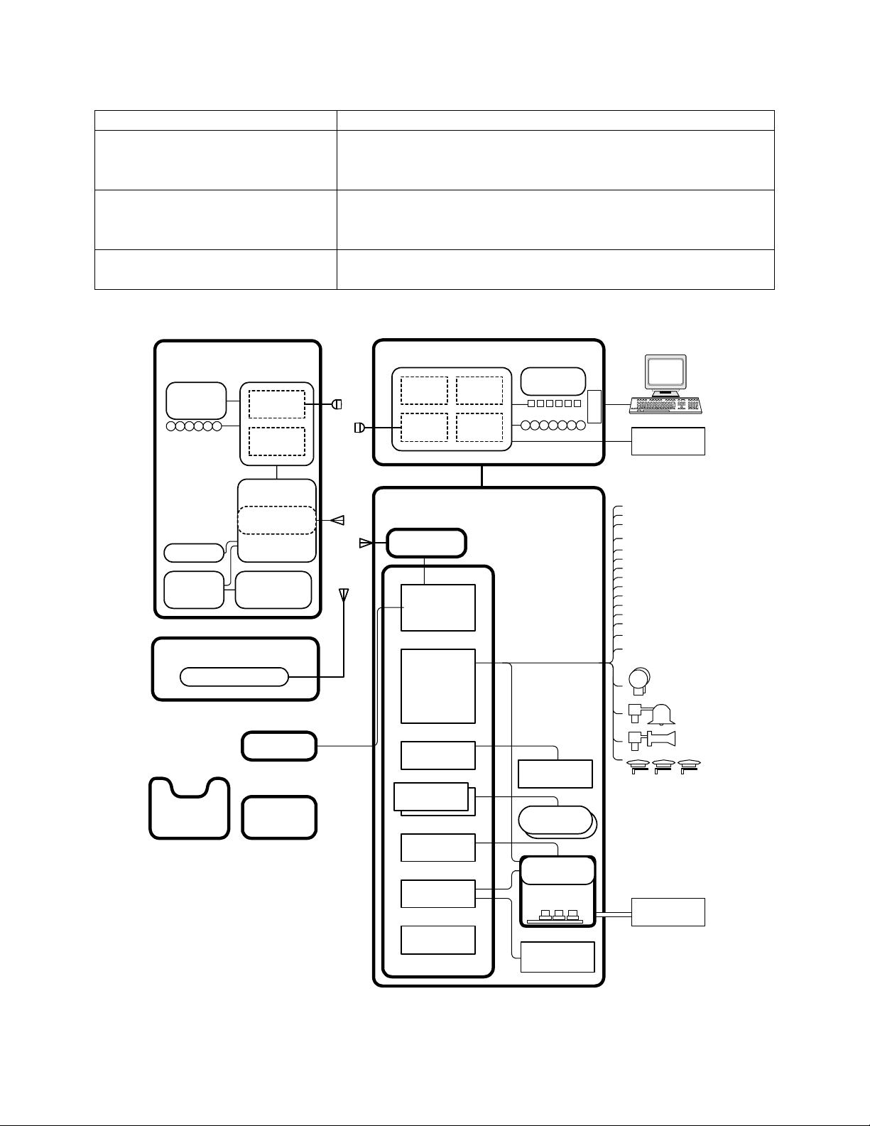
1.3 Physical Description of Equipment
The RCL system consists of On-board locomotive equipment and Off-board Operator
equipment. The Off-board equipment functions as the commanding unit and the On-board
equipment functions as the locomotive controlling unit (Figure 1.3-1).
The locomotive equipment is mechanically designed to withstand, the shock and vibration
encountered in locomotive operation. The system is sealed against dust, locomotive gasses
and oily fumes; however, it is not weatherproofed and must be sheltered from the elements.
The Operator Control Unit (OCU) is designed to meet NEMA 4 standards and to withstand
the rigors encountered in the railroad environment, however, the OCU is not waterproof
and must be sheltered from the elements.
Copyright 2002, 2003 GE Transportation Systems
Global Signaling, LLC
GE Transportation Systems Global Signaling, LLC
Proprietary and Confidential
- All rights reserved
1-1

Document No. 5002866 Rev. C (DRAFT)
28 April 2003
The major components of the RCL system are briefly described in the following table.
Table 1.3-1 Remote Control Locomotive Components
Component Description
Component Description
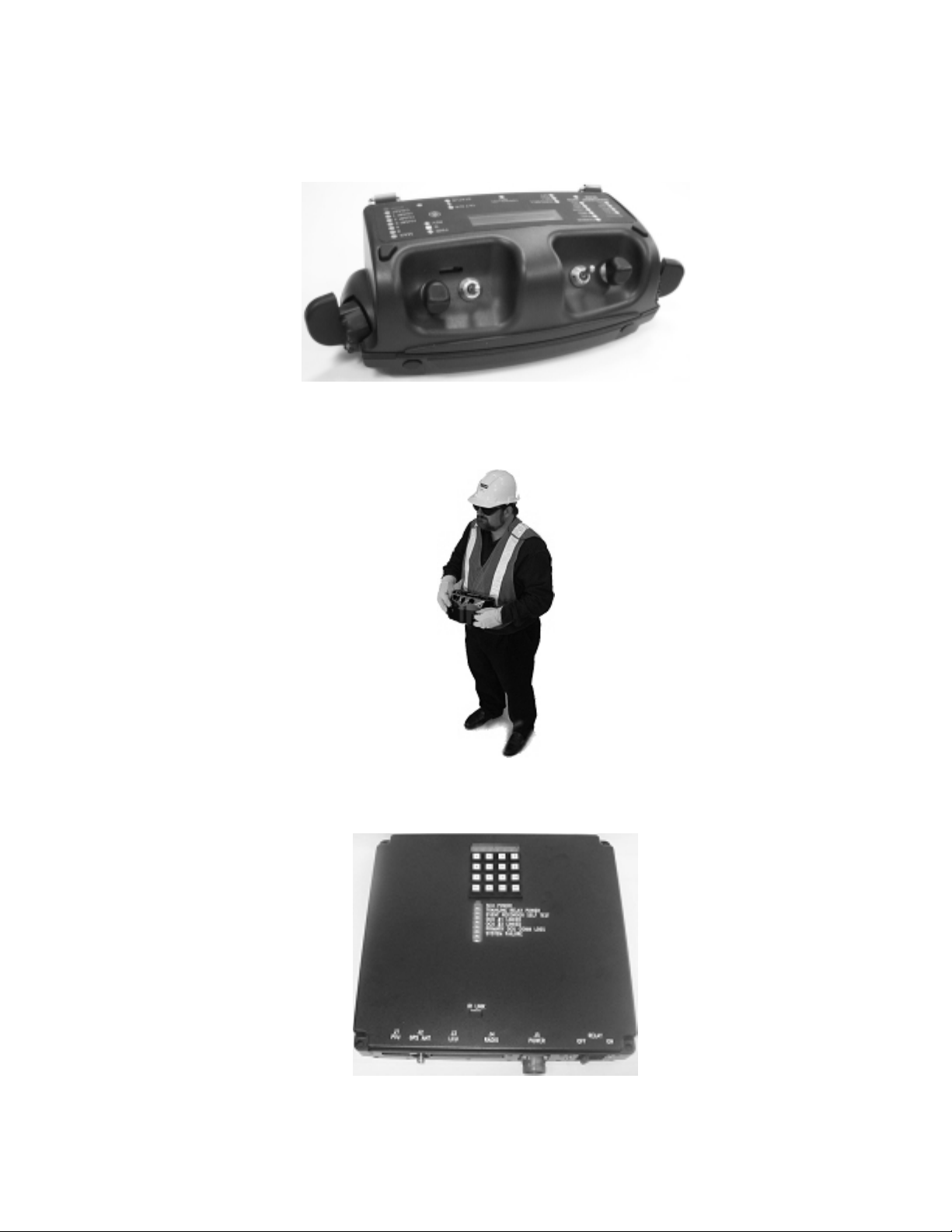
Operator Control Unit (OCU) Contains the switches and controls necessary to control the
RCL locomotive as well as the alarms and fault reporting
messages (see Figure 1.3-2).
Operator Vest Contains the D ring clips for attaching and securing the OCU
during RCL operation (see Figure 1.3-3).
Setup Control Unit (SCU) Contains the equipment on the RCL to allow for operator set-
up, system status display, and provides RCL system
interfaces to on and off train equipment (see Figure 1.3-4).
Voice Radio Contains a standard 35-watt Spectra locomotive radio. This
radio provides the capability for the SCU to send alerts and
status over the railroad voice radio network (customer
provided).
Headlight Control Module Contains the electronics used for controlling the Long and
short hood headlights. These control both Bright and Dim
operation (see Figure 1.3-5)
Locomotive Control Unit (LCU) Contains the electronics, which perform the functions
necessary to control the overall system operations. In
addition, it provides electrical isolation between the system’s
module circuitry and the locomotive’s train line signals (see
Figure 1.3-6).
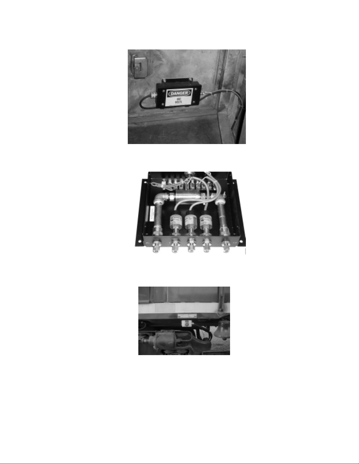
Brake Control Unit (BCU) Contains the electronic and pneumatic devices to control the
locomotive Automatic, Emergency, and Independent brakes
(see Figure 1.3-7).
AEI Tag Reader Contains the necessary tag reader electronics for detecting
track bed mounted AAR/ISO AEI tags. These tags will be
placed at the defined boundaries of operation such as yard
containment or pullback, as well as at high traffic areas, such
as grade crossings within the boundaries (see Figure 1.3-8).
Radio Module Contains the low power radios. This radio provides the closed
loop radio based communications between the OCU and the
LCU (see Figure 1.3-9).
Axle Generator Contains the electronics to detect locomotive wheel rotation
rate and convert it to speed and direction signals (see Figure
1.3-10).
Traction Motor Current Module Contains the electronics necessary to interface to the
Locomotive traction motor shunt (see Figure 1.3-11).
GE Transportation Systems Global Signaling, LLC
Proprietary and Confidential
1-2
Document No. 5002866 Rev. C (DRAFT)
28 April 2003
Component Description
Air Sensor Module (ASM) Contains the electronic and pneumatic devices used to detect
Brake Pipe airflow, Truck Brake Cylinder cut in, and Horn
activation (see Figure 1.3-12).
GPS Contains necessary equipment for Global Positioning
Satellite (GPS) location determination to supplement AEI
Tag Reader System.
Emergency Stop Buttons Two exterior and one interior mounted red mushroom
emergency stop buttons for RCL. (see Figure 1.3-13)
O
p
r
a
e
Display
LEDS
Speed
Speed Enable
Loco Brake
Loco Brake Enable
Direction
Train Brake
Pitch/Catch
Tilt Ovr-ride
Headlight
On/Off/Mode
Tilt
Power
Mngmt
RF Router (if needed)
ISM Band Radio
R
O
P
E
A
O
T
E
V
T
S
t
o
r
R
o
C
n
t
o
r
Interface
Actuator
Conditioning
Processor
ISM Band
Radio
Battery
AEI Tag
Reader
A
B
C
H
l
IRDA
T
A
RCL PTU
P
T
U
Event Downloader
Voice
n
U
t
i
Voice
Synth
IRDA
Interface
S
t
e
-
u
p
o
n
C
t
r
o
l
U
n
t
i
GPS
Receiver
Status
Control
Display
Buttons
LEDS
Radio
L
o
c
o
m
o
t
v
i
o
C
e
ISM Band
Radio
Processor
I/O
+
Drivers
I/O
Speed (2)
R
E
T
Y
R
E
G
R
Speed
Air Brake
I/O
n
t
r
o
U
l
n
t
i
Excitation
Amp
Axle
Generators
Brake
Control
Pneu.
Headlight F Brt
Headlight Dim
Headl i g h t R Brt
Alarm
A Valve
B Valve
C Valve
D Valve
Forward
Reverse
Gen Field
Manual Sand
Slow Speed Enable
Wheel Slip
PCS
Light
Pneu
Bell
Horn
Emr Stop
26-L
Power
Traction
Current
Figure 1.3-1 RCL Top Level Block Diagram
GE Transportation Systems Global Signaling, LLC
Proprietary and Confidential
1-3
Document No. 5002866 Rev. C (DRAFT)
28 April 2003
Figure 1.3-2 Operator Control Unit (OCU)
Figure 1.3-3 Operator Vest
Figure 1.3-4 Setup Control Unit (SCU)
GE Transportation Systems Global Signaling, LLC
Proprietary and Confidential
1-4

Document No. 5002866 Rev. C (DRAFT)
28 April 2003
Figure 1.3-5 Headlight Control Module
Figure 1.3-6 Locomotive Control Unit (LCU)
Figure 1.3-7 Brake Control Unit (BCU)
GE Transportation Systems Global Signaling, LLC
Proprietary and Confidential
1-5

Document No. 5002866 Rev. C (DRAFT)
28 April 2003
Figure 1.3-8 AEI Tag Reader
Figure 1.3-9 Radio Module/Router
Figure 1.3-10 Axle Generator
GE Transportation Systems Global Signaling, LLC
Proprietary and Confidential
1-6
Document No. 5002866 Rev. C (DRAFT)
28 April 2003
Figure 1.3-11 Traction Current Module
Figure 1.3-12 Air Sensor Module
Figure 1.3-13 Emergency Stop Button
GE Transportation Systems Global Signaling, LLC
Proprietary and Confidential
1-7

Document No. 5002866 Rev. C (DRAFT)
28 April 2003
1.4 Operational Overview
In conventional railroad yard switching operations without an RCL system, all car and
locomotive movements require an operator on board the locomotive as well as personnel on
the ground to direct movements and set switches.
The RCL system provides the yard crews with the ability to control the locomotive from a
portable/handheld unit, thereby eliminating the need for an operator on board the
locomotive. The yard crew can then set switches and directly control the locomotive/train
movements from the ground. Additionally, the RCL system allows one operator to transfer
control to another operator in a pitch and catch method when control of the train is needed
from another position in the yard.
The yard crew uses the portable OCU to command locomotive movement. The OCU also
provides the operator the ability to control the direction, speed, and braking of the
locomotive/train. Additionally, the OCU provides the capability to control the headlights,
manual sand, bell, and horn. The OCU provides fault and alarm status data from the
locomotive.
The LCU on board the locomotive receives the commands from the OCU and activates the
appropriate control functions. Control relays or solenoid valves control each function on the
locomotive. Sensor circuits monitor the status of the controlled functions to ensure that the
control function has been properly activated. If the status does not match the commanded
function, a miscompare alarm is generated and appropriate action is taken to ensure the
locomotive is in a safe and appropriate state.
If communications are lost between the OCU and LCU for greater than 5 seconds the LCU
will go to the Park state where the locomotive is idled and a full service automatic and
independent brake application is made. The system remains linked and if communications
are restored the Park State can be recovered and normal operations resumed. If
communications is lost for longer than the comm. loss unlink time as set in the
Configuration File, the LCU will go to the Safe State where the emergency brakes are
applied, the locomotive is set to idle, and the system is unlinked.
1.5 OCU Commanded Functions
The OCU detects the operator inputs and transmits these commands to the LCU. The LCU
then activates the appropriate control signals to carry out the commanded control function.
Table 1.5-1 lists the normal command functions transmitted to the LCU.
Table 1.5-1 OCU Command Functions
Electrical Functions Pneumatic Functions
Electrical Functions Pneumatic Functions
Direction Automatic Brake Applications and Releases
Set Speed Independent Brake Applications and Releases
Bell Emergency Brake Applications and Releases
Horn
Sand
Headlight
GE Transportation Systems Global Signaling, LLC
Proprietary and Confidential
1-8
Document No. 5002866 Rev. C (DRAFT)
28 April 2003
1.6 LCU Control and Status Functions
When the LCU receives commands from the OCU, it activates the appropriate locomotive
control lines needed to perform the commanded control function. Locomotive status lines
are monitored to ensure that the proper functions have been activated and to provide
feedback for function control loops. Table 1.6-1 and Table 1.6-2 lists the normal LCU
controlled and monitored functions.
Table 1.6-1 LCU Controlled Functions
Electrical Functions Pneumatic Functions
Electrical Functions Pneumatic Functions
Direction: (FO, RE) Equalizing Reservoir (DEC, FST, SLO)
Throttles: (AV, BV, CV, DV) Independent Brake: (IBA, IBR)
Generator Field: (GF) Bail (ABL)
Manual Sand Emergency: (EBA)
Slow Speed Enable Backup Emergency: (BUEMV)
GF Excitation Control (Analog Control) Emergency Reset: (EBR)
Head Light Control Horn
Strobe Lights (if equipped) Bell
Vigilance Disable (if equipped)
Table 1.6-2 LCU Monitored Functions
Electrical Functions Pneumatic Functions
Electrical Functions Pneumatic Functions
Emergency Stop Buttons ER Pressure, BC Pressure, MR Pressure
Rear Headlight Switch Position BP Pressure
Wheel Slip Front and Rear Truck BC Pressure > 25 psi
PC Switch Bell
Traction Motor Current Horn
Axle Generator #1 Speed Feed (Brake)Valve (FV)
Axle Generator #1 Direction Penalty Pipe
Axle Generator #1 Speed Switch Pipe
Axle Generator #1 Direction BP Flow
Locomotive Alarm
Manual Sand
Governor Shutdown
Hot Engine
Ground Fault
GE Transportation Systems Global Signaling, LLC
Proprietary and Confidential
1-9
Document No. 5002866 Rev. C (DRAFT)
LR
SS RS RR
RI
28 April 2003
2. CONTROLS AND INDICATORS
This Chapter provides the operator with a comprehensive background for operation of all
controls and an understanding of the monitoring indications. Each control and indicator
located anywhere on the system is listed and described in one of the tables provided.
Refer to Figure 2.1-1 and 2.1-2, OCU layout, when reading Table 2.1-1 and Table 2.1-2;
Figure 2.2-1, SCU Assembly, when reading Table 2.2-1 and 2.2-2; and Figure 2.3-1 and
2.3-2, LCU Assembly, when reading Table 2.3-2.
No attempt is made to describe any circuitry in detail. Only functional descriptions are
provided. For detailed circuit descriptions, see the Service Manual.
2.1 Operator Control Unit (OCU)
The OCU contains controls, a display, a speaker and an Infra-Red Port (see Figure 2.1-1).
Table 2.1-1 lists and describes the Operator controls. Table 2.1-2 lists and describes the
OCU outputs. Commanded functions are indicated on the OCU display by a flashing LEDs
and the actual locomotive status is indicated by a solid LEDs. When the actual locomotive
status matches the commanded value the status LED is solid.
ABS
BHS
IR Port
TOR
IBS
ABI
IBI
BHI
Display
SI/TOI
SSI
Future use
(spare)
Future use
(spare)
PCC/LNK
BatterySonalert MHL
PWR
Figure 2.1-1 Operator Control Unit – Actuators
GE Transportation Systems Global Signaling, LLC
Proprietary and Confidential
2-1
Document No. 5002866 Rev. C (DRAFT)
28 April 2003
Table 2.1-1 Operator Inputs
Function Description
Function Description
Speed Selector (SS) (Flat Yard OCU) The Speed Selector provides eight positions
that result in the OCU transmitting speed and
stop commands. Movement of the Speed
Selector also provides a signal to reset the
vigilance timer.
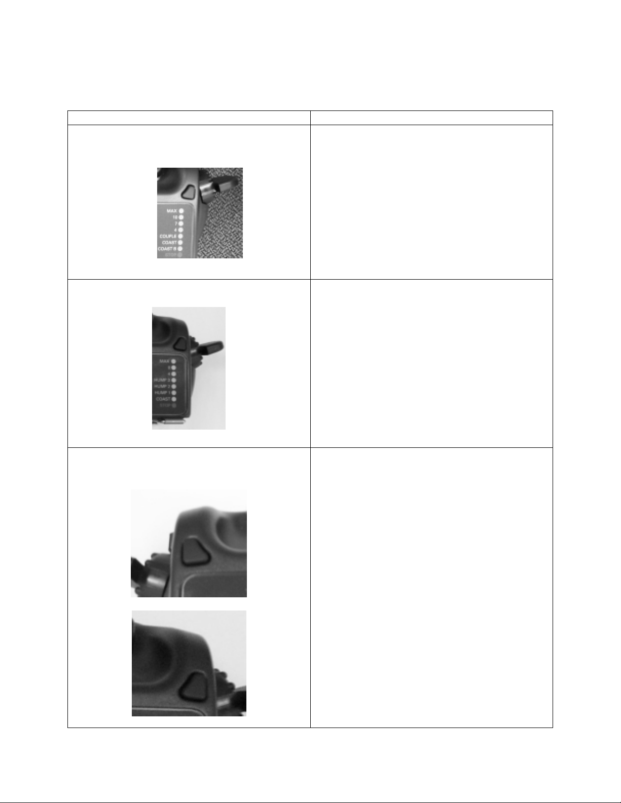
Speed Selector (SS) (Hump Yard OCU)
The Speed Selector provides eight positions
that result in the OCU transmitting speed and
stop commands. Movement of the Speed
Selector also provides a signal to reset the
vigilance timer.
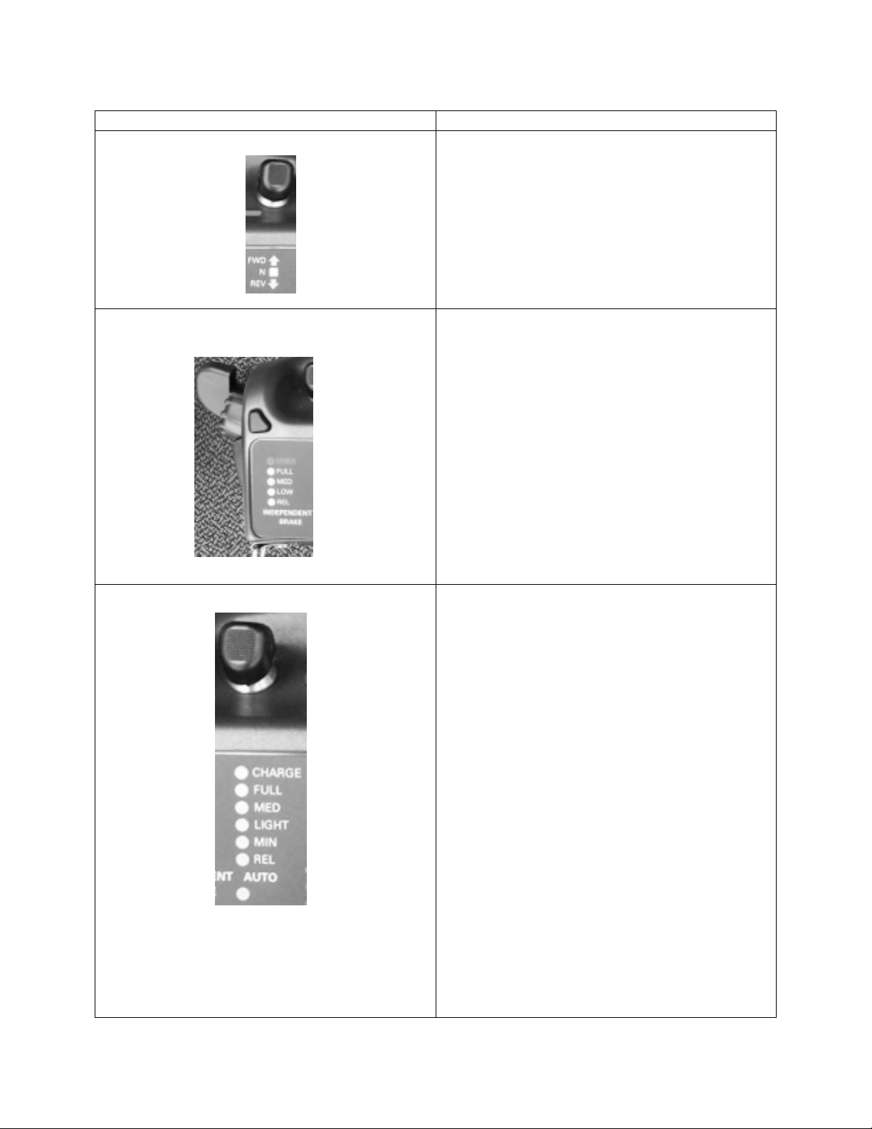
Left Reset (LR)
Right Reset (RR)
These switches need to be pressed first to
allow the following OCU actions within 3
seconds:
• SS out of stop
• ABS from full to charge
Also these buttons:
• Command Manual sanding if pressed for
more than 5 seconds:
• Resets OCU vigilance.
• Approves linking of secondary OCU
• Commands sleep mode option
• LR:
i) unfreezes locomotive status screen
ii) lowers OCU LED brightness
• RR:
i) freezes locomotive status screen
ii) increases OCU LED brightness
GE Transportation Systems Global Signaling, LLC
Proprietary and Confidential
2-2
Document No. 5002866 Rev. C (DRAFT)
28 April 2003
Function Description
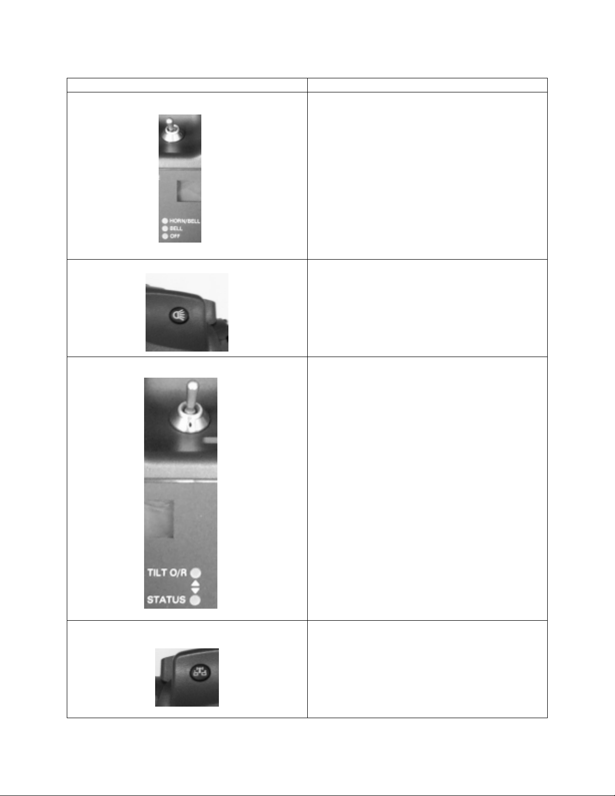
Reverser Selector (RS)
The RS is a three-position toggle switch:
(a) FWD Position: Activates Locomotive
Forward trainline (TL8)
(b) N Position: Neutral, no direction
commanded
(c) Rev Position: Activates Locomotive
Reverse trainline (TL9)
Independent Brake Selector (IBS)
The IBS provides five positions that result in
the OCU transmitting the following
independent brake commands:
(a) emergency
(b) full
(c) medium
(d) low
(e) released
Actuation of the IBS also provides a signal to
reset the vigilance timer.
Automatic Brake Selector (ABS)
The ABS is a three-position toggle switch. The
Center position is a no change position. The
ABS toggle position away from operator’s
body is a momentary position that results in the
OCU transmitting a command to the next
sequential brake application in the following
sequence:
(a) Release
(b) Minimum (7 psi reduction)
(c) Light (15 psi reduction)
(d) Medium (20 psi reduction)
(e) Full (26 psi reduction)
(f) Charge
The ABS toggle position toward operator’s
body for at least 2 seconds results in the OCU
transmitting a direct release command.
ABS also resets OCU vigilance.
GE Transportation Systems Global Signaling, LLC
Proprietary and Confidential
2-3
Document No. 5002866 Rev. C (DRAFT)
28 April 2003
Function Description
Bell and Horn Selector (BHS)
The BHS is a three-position toggle switch. The
BHS toggle position toward the operator is bell
and horn off. The BHS switch center position
results in locomotive bell on with horn off. The
BHS toggle position away from the operator is
a momentary position and results in a bell and
horn on.
BHS also resets the vigilance timer.
Manual Headlight (MHL)
The MHL is a push button that results in the
OCU transmitting a headlight command to
control the brightness level (Off, Dim, or
Bright) of the Locomotive consist’s front and
rear headlights. MHL resets the vigilance
timer.
Tilt Over-ride / Tilt Test Over-ride / Status
(TOR)
The TOR is a three-position toggle switch.
TOR toggle in the center position shall be in
the neutral position.
TOR toggle position toward the operator is a
momentary position and adjusts the OCU
display for status. Toggling the switch Multiple
times steps the Status display through the
following status displays:
• Loco Status
• OCU Status
• Link Status
TOR toggle position away from operator is a
momentary position for tilt timer extend and
tilt test. The Tilt Override feature will be
activated for up to 60 seconds when the switch
is toggled to this position. Changing any OCU
control will cancel the tilt override timer.
TOR also resets the vigilance timer.
Pitch Catch Control / Link (PCC/LNK)
The PCC/LNK is a momentary switch that:
• Starts OCU linking via infrared port to SCU
• Pitch and catch operation to move locomotive
control to a secondary OCU
• Resets OCU vigilance.
GE Transportation Systems Global Signaling, LLC
Proprietary and Confidential
2-4

Document No. 5002866 Rev. C (DRAFT)
28 April 2003
Function Description
Power (PWR)
The PWR is a push button switch that performs
a soft power on/off of the OCU and must be
held for 5 seconds to power off the OCU.
GE Transportation Systems Global Signaling, LLC
Proprietary and Confidential
2-5
Document No. 5002866 Rev. C (DRAFT)
LR
SS RS RR
RI
28 April 2003
ABS
BHS
IR Port
TOR
IBS
ABI
IBI
BHI
Display
SI/TOI
SSI
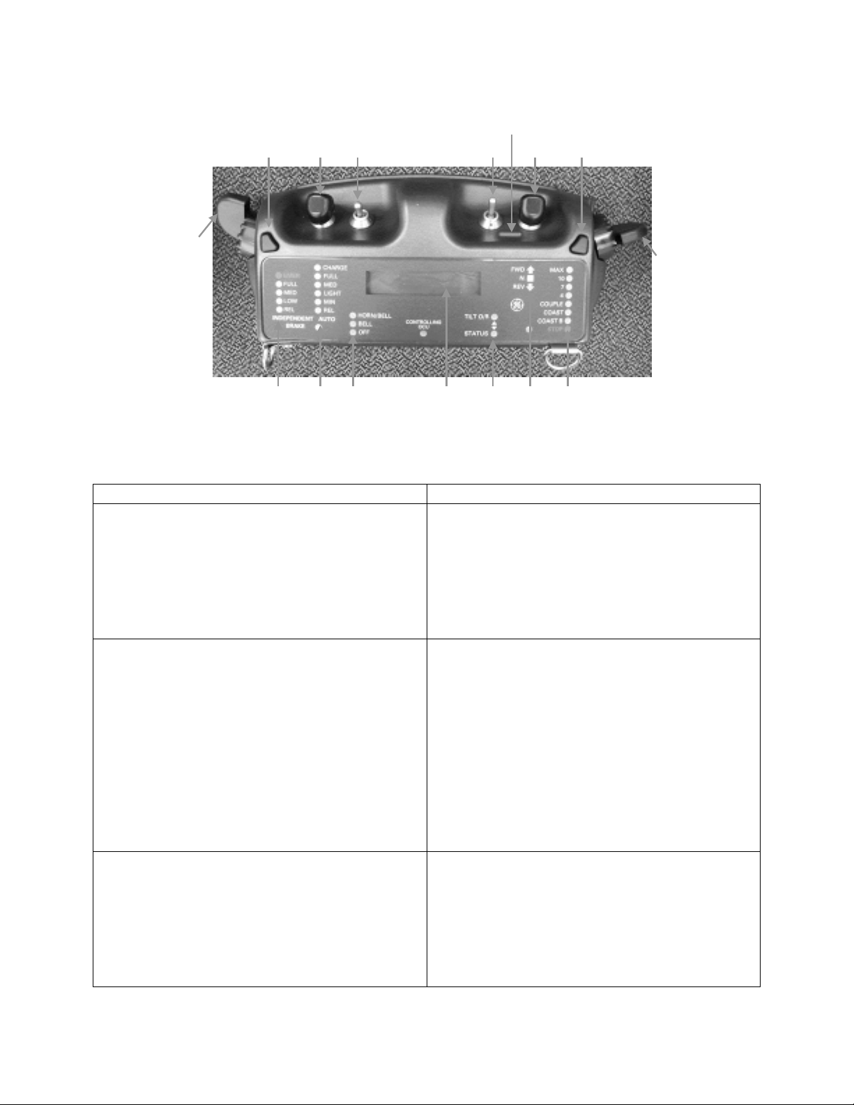
Figure 2.1-2 Operator Control Unit - Indicators
Table 2.1-2 OCU Outputs/Indicators
Function Description
Display The display is used to report system events and
status and fault and alarm data. Toggling the
TOR actuator to the Status position selects the
following system status:
1. Loco Status
2. OCU Status
3. Link Status
Independent Brake Indicator (IBI)
The IBI is the status indicator for the
Independent Brake Selector (IBS). It indicates
the actual independent brake level (illuminated
indicator) and the commanded independent
brake level (flashing indicator) for the LCU.
The following braking levels are indicated:
(a) EMER
(b) FULL
(c) MED
(d) LOW
(e) REL
Automatic Brake Indicator (ABI)
The ABI is the status indicator for the
Automatic Brake Selector (ABS). It indicates
the actual automatic brake level (illuminated
indicator) and the commanded automatic brake
level (flashing indicator) for the LCU. The
following braking levels are indicated:
(a) CHARGE
GE Transportation Systems Global Signaling, LLC
Proprietary and Confidential
2-6

Document No. 5002866 Rev. C (DRAFT)
28 April 2003
Function Description
(b) FULL
(c) MED
(d) LIGHT
(e) MIN
(f) REL
Bell and Horn Indicator (BHI) The BHI is the status indicator for the Bell and
Horn Selector (BHS). It indicates the
commanded Bell and Horn settings for the
LCU. The following settings are indicated:
(a) HORN-BELL
(b) BELL
(c) OFF
Controlling OCU (CO) The CO is the status indicator for the
Controlling OCU. When this LED is
illuminated, this OCU is in control of the RCL
locomotive (primary).
Status Indicator (SI) The SI is the status indicator for the Display
status. When this indicator is illuminated, the
OCU Display is displaying status information.
Reverser Indicator (RI)
The RI is the status indicator for the Reverser
Selector (RS). It indicates the actuator position
and the commanded direction for the LCU. The
following settings are indicated:
(a) FWD
(b) N
(c) REV
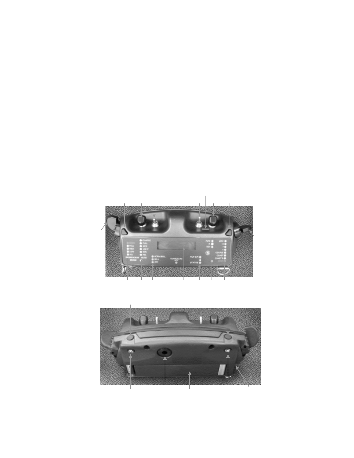
Speed Selector Indicator (SSI)
The SSI is the status indicator for the Speed
Selector (SS). It indicates the actual LCU
speed (illuminated indicator) and the
commanded locomotive Speed level (flashing
indicator) for the LCU. The following braking
levels are:
(a) MAX
(b) 10
(c) 7
(d) 4
(e) COUPLE
(f) COAST
(g) COAST (B)
(h) STOP
GE Transportation Systems Global Signaling, LLC
Proprietary and Confidential
2-7

Document No. 5002866 Rev. C (DRAFT)
28 April 2003
Function Description
Tilt Over-ride / Tilt Test Indicator (TOI) The TOI is the status indicator for the Tilt
Over-ride/Tilt Test Switch (TOR). The
indicator is illuminated when TOR is pressed
and flashes to indicates that the tilt by-pass or
tilt test functions are enabled.
Ambient Light Detector (ALD) The OCU provides a photo detector to
determine ambient lighting conditions and, if
selected, automatically adjust the OCU display
illumination for day/night operation.
Audible Output The audible device is a dual tone output used
for normal annunciations (low level, chirping
tone) and emergency warnings (high level,
continuous tone).
Infra-Red Port The IR port is an Infra-red interface transceiver
used for OCU to SCU linking. The IR port is
also used for upgrading the OCU software.
2.2 Setup Control Unit (SCU)
The SCU is part of the RCL On board equipment and provides the human interfaces
required on the locomotive. It contains a keypad, circuit breaker, status LEDs, Synthesizer,
PTU interface port, Infra-Red Port and other electronic devices to allow for operator set-up,
system status display, (see Figure 2.2-1). Table 2.2-1 lists and describes the Operator input
switches and actuators. Table 2.2-2 lists and describes the SCU outputs and Indicators.
Figure 2.2-1 Setup Control Unit (SCU)
GE Transportation Systems Global Signaling, LLC
Proprietary and Confidential
2-8

Document No. 5002866 Rev. C (DRAFT)
28 April 2003
Table 2.2-1 SCU Inputs
Function Description
Relay Circuit Breaker The Relay Circuit Breaker provides power to
the LCU locomotive control relays
Keypad The Keypad is a sixteen (16) button keypad for
control of the status display and entry of
information. The keypad is disabled when the
LCU is linked to the OCU.
GPS Input The GPS input provides a connection for the
GPS antenna.
Table 2.2-2 SCU Outputs
Function Description
Display The display is a 2 line, 16 character display. It
is used to report system status and diagnostic
data.
Infra-Red Port The IR port is used for OCU to LCU linking,
and data transfer.
Status LEDs Status LEDs are provided for the following
items
(a) SCU power (green)
(b) Trainline relay Power (green)
(c) Event Recorder Continuous Self-Test
(green)
(d) OCU #1 linked (green)
(e) OCU #2 linked (green)
(f) Primary OCU Comm Loss (red)
(g) System Failure (red)
(h) Spare
PTU Port The PTU port provides the serial channel
interface to a Laptop computer and is used for
downloading Event Recorder data.
Voice Radio The radio connection provides an interface to
the voice radio.
GE Transportation Systems Global Signaling, LLC
Proprietary and Confidential
2-9

Document No. 5002866 Rev. C (DRAFT)
28 April 2003
3. INTRODUCTION
This chapter provides recommended guidelines for operating the RCL system and includes
additional information to assist the operator in understanding the various modes of
operation.
The procedures are written to assist the railroad in establishing safe operating procedures
for the RCL System; however, they are not intended to replace standard locomotive
operating procedures or approved railroad practices. Standard railroad operating procedures
should take precedence.
A periodic checkout of the RCL system is recommended. This checkout should include a
complete test of all system functions as well as checks of the radios. For detailed circuit
descriptions, see the Service Manual.
3.1 Operator Interface Overview
The Operator Control Unit (OCU) is the primary operator interface. The OCU operation
begins at RCL system linking and progresses through the required tests until the operator
has complete control of the RCL locomotive.
3.2 Initial Conditions
The following conditions are required prior to RCL start-up and operation:
1. The RCL System is installed and operating properly.
2. The operator is completely familiar with locomotive operating procedures and
established railroad practices and is duly authorized by the railroad to operate an RCL
equipped train.
3. All RCL power switches and circuit breakers in the RCL locomotive are in the OFF
position.
Note – If the locomotive is in Manual Mode all the RCL switches and circuit breakers will
be on.
4. The operator puts fresh batteries in the OCU and verifies battery charge.
5. The operator puts on the operator vest and adjusts for comfort.
3.3 Preparing RCL Equipment for Service
Preparation of the RCL equipment is done in steps as indicated in the following sections.
Note – Locomotive Independent brakes (cabstand) should not be released until after the
RCL system is setup.
3.3.1 Locomotive Set Up for RCL Operation
Set the following switches on the RCL locomotive to the positions indicated.
GE Transportation Systems Global Signaling, LLC
Proprietary and Confidential
3-1

Document No. 5002866 Rev. C (DRAFT)
28 April 2003
Table 3.3.1-1 Locomotive Setup
Switch Position
Control and Fuel Pump Switch ON
Dynamic Brake Circuit Breaker (if equipped) OFF
Reverser NEUTRAL (Handle Removed)
Unit Isolation Switch RUN
Automatic Brake Valve RELEASE
Brake Valve Cut-out FREIGHT or IN
MU2A LEAD
Independent Brake Handle RELEASE
Engine Run Switch ON
Generator Field Switch OFF
Cab Stand Headlight Switch OFF
Remote Headlight Select Switch Set for Normal MU Operation
Note – All units which form the part of the RCL consist must be coupled to the RCL
equipped unit in the conventional trailing unit mode.
Set the RCL System switches to the position indicated:
1. RCL Manual/RemoteValve –Remote position
Note –When RCL Manual/Remote valve is placed in the Remote position, the locomotive
will go to emergency.
2. RCL main Circuit Breaker -ON
3. SCU Relay Circuit Breaker -ON
After system initialization the RCL SCU unit turns on the following LED status indicators:
LCU/SCU Power (green), Train line Relay Power (green), and Event Recorder Continuous
Self-Test (green). The SCU displays “Low MR” until the Main Reservoir pressure is
greater than 80 psi. The SCU then displays the “Setup Emergency” message.
After system initialization the RCL LCU unit enters the Setup State where it will wait for
link commands from the OCU. While in the Setup State the LCU will be in the Safe mode
in which the emergency brakes are applied, the Independent Brakes are set to full, and the
Throttle is set to Idle.
If the LCU is not linked to an OCU within 90 seconds then the LCU enters the Standby
Mode. In this mode, the LCU remains powered up but relinquishes control of the
locomotive air brakes and allows the locomotive to be operated conventionally. When the
LCU enters the Manual mode (after 90 seconds) the emergency valves are closed which
allows manual recovery of the train brake pipe using the automatic brake handle. When the
brake pipe is recovered and the brake pipe pressure rises above 65 psi, then the LCU
releases the Independent brakes and turns control over to the locomotive operator. When
the LCU receives a link command from an OCU it will then re-enter the Setup State.
GE Transportation Systems Global Signaling, LLC
Proprietary and Confidential
3-2

Document No. 5002866 Rev. C (DRAFT)
28 April 2003
3.3.2 Operator Control Unit Setup
Set the following switches on the OCU to the positions indicated:
Table 3.3.2-1 OCU Switch Setup
Switch Position
Speed Selector (SS) STOP
Reverser Selector (RS N
Independent Brake Selector (IBS) EMERGENCY
Bell / Horn Selector (BHS) OFF
Power (PWR) ON
3.3.3 RCL Equipment Shutdown Procedure
The following procedure should be followed to shutdown the RCL system:
1. With the train stopped; set the Speed Selector to STOP, the Reverser to the Neutral
(N) position, The Bell and Horn Selector (BHS) to OFF, and the independent brake
to FULL or Emergency.
2. Unlink the system by setting the PWR switch on the Primary OCU to the OFF
position (press and hold pwr for 5 seconds). Follow the directions on the OCU
display to power down OCU. The OCU transmits the Unlink command to the LCU
and after receiving an acknowledge command from the LCU that it is the Safe mode,
and then powers off.
3. When the RCL system on the locomotive receives the unlink command from the
Primary OCU, it enters the Setup State and initiates an Emergency Brake Application,
sets a Full Independent Brake Application, sets the Throttle to idle and enters the Safe
mode. The LCU then transmits an acknowledge command to the OCU indicating that
it is in the Safe mode.
4. After 90 seconds the LCU enters the Manual Mode, closes the emergency valves, and
allows the locomotive operator to operate the locomotive conventionally.
The locomotive can now be operated conventionally without having to power off the LCU,
cutout any pneumatic valves, or re-configure any switch settings. Alternatively, the LCU
can be powered off and cutout as follows:
1. Place the RCL Main Circuit Breaker to OFF.
2. Move the RCL Manual/Remote Valve to the Manual position.
3. Configure the locomotive for conventional lead operation.
3.4 System Linking and Testing
When the train has been made up properly and the RCL system has been prepared per the
previous instructions, system linking and safety checks can be performed. On initial power
up, the OCU performs a display and audible alarm test. All display indicators light in
sequence, each line of the display is exercised, and the audible alarm sounds. When all
GE Transportation Systems Global Signaling, LLC
Proprietary and Confidential
3-3

Document No. 5002866 Rev. C (DRAFT)
28 April 2003
indicators and the audible alarm have been verified, the display shows GETS GS
LOCOTROL RCL, and the OCU is now ready for linking to the Setup Control Unit
(SCU). If the locomotive is not set up properly for RCL operation (i.e., Air brake cutout
cock not cut in, Locomotive trucks cutout, automatic brake handle not in release, etc.) or an
alarm condition exists on the locomotive, the SCU display will indicate which device that is
improperly setup or the RCL fault that is active. If properly set up, the SCU will indicate
Setup Emergency when the LCU is in the Setup State or Manual Mode when it is in the
Manual mode and is ready for linking with the OCU.
3.4.1 Linking RCL Operation
To begin the RCL linking process, follow the guidelines outlined below:
1. Hold the OCU so that its Infrared Port is pointed at the SCU Infrared port and press
and release the PCC/Link button on the OCU. (see Figure 3.4.1-1) The OCU will
give a Linking LCU and Radio Testing message.
2. Verify that the OCU and the SCU are linked together by observing that the OCU
displays Linked to Locomotive, Loco ID: XXXX and that the Green OCU # 1
Linked status LED is lit. The first OCU that links to the SCU is defined as the
Primary OCU and the Controlling OCU LED illuminates on the OCU to indicate that
it is the controlling OCU for the RCL system.
3. Once linked, the SCU will display Primary Tilt Test Not Complete. Press and hold
the tilt override switch forward. Rotate the OCU greater than 45 degrees from
horizontal until the SCU message disappears. The locomotive voice Radio will send a
voice message that the tilt test is completed and the locomotive number. The RCL
system remains in the Setup State (or transitions to the Setup State if it was in the
Manual mode) with the emergency brakes applied, the Independent Brakes set to Full,
and the Throttle in Idle. Release independent brakes on cabstand.
4. Leave the locomotive and proceed to the area of intended operation.
GE Transportation Systems Global Signaling, LLC
Proprietary and Confidential
3-4

Document No. 5002866 Rev. C (DRAFT)
28 April 2003
Figure 3.4.1-1 Linking
A secondary OCU can be linked to the LCU for use during Pitch and Catch operations.
Linking the secondary OCU is accomplished in the same manner as the Primary OCU
except the Primary OCU must acknowledge and authorize the secondary OCU linking.
The process for linking the secondary OCU is outlined below:
1. Hold the second OCU so that its Infrared Port is pointed at the SCU Infrared port and
press and release the PCC/Link button on the OCU. The Primary OCU operator will
get a Secondary OCU Link message on their display and within 5 seconds the
operator must press the LR or RR button on the OCU to authorize the second OCU to
Link.
2. Verify that the second OCU and the SCU are linked by observing the Locomotive
road number on the second OCU display and that the Green OCU # 2 Linked status
LED is lit. The Controlling OCU LED on the secondary OCU remains off.
3. If the Setup Emergency has been recovered by the Primary OCU, the locomotive will
be put into Park State. Once the secondary OCU is linked a secondary OCU Tilt test
must be performed using the same method as the primary Tilt test. If the Setup
Emergency has not been recovered prior to linking a secondary OCU, the RCL
system will remain in the Setup State.
3.4.2 Emergency Valve Test
The Emergency Valve Test verifies the proper operation of the RCL locomotive
emergency. The test runs automatically when the automatic brakes are released for the first
time after linking.
The operator moves the Independent Brake Selector (IBS) from the EMERGENCY
position to the RELEASE position. The SCU will display EMV Test in Progress. The
GE Transportation Systems Global Signaling, LLC
Proprietary and Confidential
3-5

Document No. 5002866 Rev. C (DRAFT)
28 April 2003
OCU will display Consist Recovering and if the test passes, BP will recover and the OCU
will display Consist Ready.
Upon successful completion of the Link operation, recovery of the Set Up Emergency, and
verifying the emergency valves, the Locomotive Control Unit (LCU) transitions into the
Ready State. The Ry State allows an OCU operator to control the locomotive’s speed and
brakes. The SCU display Remote Mode on the display.
3.4.3 System Status Functions
The RCL system status is displayed on the OCU display. Select the status functions using
the TOR actuator. By toggling the TOR actuator toward the Status position, the OCU
display toggles through the each status function. As the operator selects each status
function, the OCU scrolls through the information related to the selected item. The selected
status functions and information provided is as follows:
Table 3.4.3-1 Status Functions
Status Function Information Provided
Status Menu Status List
Pitch to Proyard (If a Hump Yard OCU is
being used)
1. Pitch to Proyard…
Press PCC to Pitch
Loco Status 1. Brake Pipe: XX psi
BP Flow: YY scfm
2. Main Res: XX psi
Brake Cyl: YY psi
3. Loco speed: XX mph
Loco Thr o t : Z
4. Headlight Command:
Dim (Bright) (Off)
OCU Status 1. LED Intensity: AUTO (XX %)
Adjust with LE/RE
2. Ver: 8000451-6XX
SW Date: MM/DD/YY
3. Battery Life
XX hrs YY mins
4.
Link Status 1. Radio Link Status
Unlinked (Linked to Loco XXXX)
2. IR Linked Status
Unlinked (Linked)
Note: The Loco Status Screen can be frozen with the RR button and unfrozen with the LR
button while the loco status is being displayed.
GE Transportation Systems Global Signaling, LLC
Proprietary and Confidential
3-6

Document No. 5002866 Rev. C (DRAFT)
28 April 2003
3.4.4 System Operating States
The following sections identify and describe the main operating States of the RCL system
and the criteria used to transition between states.
3.4.4.1 Initialization (Power Up) State
Upon power up the LCU performs a power up self-test and checks the status of the
locomotive, brake, and yard containment.
If the self-test passes, the LCU system transitions to the Setup State. Failure of the self-test
holds the system in the Initialization State and an alarm message is displayed on the SCU
display.
3.4.4.2 Setup State
In the Setup State, the LCU commands the air brake system to emergency, the independent
brakes to maximum, and the locomotive to Idles with direction Neutral. The SCU display
shows Setup Emergency. The LCU also checks for system faults, improper system setup,
and invalid configuration parameters.
If the LCU system checks pass then the LCU can be linked to the OCU. Failure of the
system checks holds the system in the Setup State, displays an alarm message on the SCU
display, and prevents the LCU from Linking with the OCU.
3.4.4.3 Manual Mode
If the LCU remains in the Setup State for 90 seconds without linking to an OCU, then the
LCU transitions to the Manual Mode. When the LCU transitions to the Standby Mode, the
SCU display shows Manual Mode. The locomotive is still in emergency with the LCU
maintaining a Maximum (Full) independent brake application. The brake pipe may now be
recovered manually using the automatic brake handle on the cabstand. When the brake pipe
pressure rises above 65 psi, the LCU releases the independent brakes and the locomotive is
now suspended from RCL operation and can be operated conventionally.
The LCU remains in the Manual Mode until a Link command is received from an OCU via
the Infra – Red port. When a Link command is received, the LCU re-enters the Setup State,
applies the emergency brakes, sets the independent brakes to maximum (Full). The LCU
then processes the linking commands from the Setup State as outlined above.
3.4.4.4 Ready State
Upon successful completion of the Linking sequence with the OCU, recovery of the Setup
emergency, and verification of the emergency valves, the LCU transitions to the Ready
State. The Ready State is the system operational State and allows the operator to control the
following:
• Locomotive Speed
• Independent Brakes
• Automatic Brakes
• Bell
GE Transportation Systems Global Signaling, LLC
Proprietary and Confidential
3-7

Document No. 5002866 Rev. C (DRAFT)
28 April 2003
• Headlights
• Horn
• Sand
The system monitors the yard containment to ensure that the system is operating safely
within the proper boundaries.
The system also monitors all critical parameters and subsystems to ensure no fault
conditions are present. If fault conditions are detected, the system transitions to either the
Park State or the Safe State, depending on the severity of the fault.
The System returns to the Setup State if it receives an Unlink command from the
controlling OCU or if it unlinks automatically due to an extended loss of OCU
communications.
3.4.4.5 Park State
When a minor fault is detected, the system enters the Park State. Minor faults result from
situations where the locomotive should be stopped until the fault is resolved, but does not
warrant an emergency brake application.
Minor faults result in the following:
• Full Service Automatic Brake Application
• Full Independent Brake application
• Direction Neutral
• Throttle Idle
The system will remain in the Park State until:
• The Fault is Cleared
• The locomotive has stopped
• Primary operator acknowledges the fault by moving the Speed Selector to the STOP
position and the IBS to the FULL position as prompted by the OCU.
3.4.4.6 Safe State
The system enters the Safe State when a Major Fault is detected. Major Faults result from a
situation where the locomotive needs to be stopped using an emergency brake application.
For Major Faults, the system commands the locomotive to a Safe State which consists of:
• Emergency Brake Application
• Full Independent Brake Application
• Direction Neutral
• Throttle Idle
The system will hold the locomotive in the Safe State until:
GE Transportation Systems Global Signaling, LLC
Proprietary and Confidential
3-8

Document No. 5002866 Rev. C (DRAFT)
28 April 2003
• The Fault has been cleared
• A 60 second Emergency Brake timer has elapsed. (The OCU display shows a 60
seconds count down timer when the IBS is placed in the Emergency position to
indicate the time remaining).
• The operator acknowledges the fault by moving the SS actuator to the STOP position
and the IBS actuator to the EMERGENCY position as prompted by the OCU.
• The Operator moves the IBS actuator from the EMERGENCY position to the
RELEASE position.
3.5 Control Functions
3.5.1 Air Brake Functions
The LCU provides all air brake control of the locomotive and train brake functions
including Multiple Unit (MU) capability and emergency brake control. The brake system is
operated with the Brake Valve always cut in to ensure operation is allowed only when
automatic braking capability is available.
3.5.1.1 Automatic Brake
Automatic brake applications can be initiated by the operator using the OCU ABS switch as
follows:
1. Push the ABS switch away from operator and then release to increase brake
application one level
2. REL is 0 psi reduction
• MIN is 7psi reduction
• LIGHT is 15 psi reduction
• MED is 20 psi reduction
• FULL is full service reduction
3. The solid LED on the indicator shows switch position and the flashing LED shows
current brake level on the locomotive.
4. Operator releases brake application by pulling back on the ABS for 2 seconds.
Note: Automatic brakes are bailed for an automatic brake applications except full and
emergency.
3.5.1.2 Charge
Charge will recharge locomotive brake pipe and release automatic brakes. To initiate
charge:
1. Press LR or RR on the OCU and move ABS immediately from FULL to CHARGE
position.
2. From REL pull back for 5 seconds on TBA to wrap it back to CHARGE.
GE Transportation Systems Global Signaling, LLC
Proprietary and Confidential
3-9

Document No. 5002866 Rev. C (DRAFT)
28 April 2003
To release from charge pull back of ABS momentarily.
Note: i) Locomotive is not allowed to move while in charge.
ii)If MR is less than 110 psi the RCL system will “dry charge” the locomotive by
setting throttle to Notch 4 (Direction is Neutral).
3.5.1.3 Independent Brakes
The locomotive independent brake functions are controlled manually by the operator via the
Operator control Unit (OCU) or automatically (during speed control operation) by the LCU.
The operator initiates independent brake applications by rotating the independent brake
control on the left side of the OCU. The operator can select the following independent
brake setting as shown in Table 3.5.1.3-1 by moving the independent brake controller to the
appropriate position.
Table 3.5.1.3-1 IBS Brake Cylinder Pressure
IBS Setting Brake Cylinder Pressure
REL 0 psi
LOW 25 psi
MED 45 psi
FULL > 65 psi
Note: The locomotive brake cylinder pressure is determined by the J type relay valve
installed on the locomotive and the actual brake cylinder pressure may vary from those
noted above in Table 3.5.1.3-1. See Table 3.5.1.3-2 below.
Table 3.5.1.3-2 Various J Type Relay Valve Brake Cylinder Pressures
J Type Valve Brake Cylinder Pressure
J8.6 38 psi
J1 45 psi
J1.6 72 psi
The LCU will automatically apply independent brakes as needed to control the train speed.
An automatic Bail feature is provided in the RCL system to release the locomotive brakes
after any automatic brake application. When the LCU commands an automatic brake
application less than Full Service, the BAIL function will be activated for 20 seconds. The
locomotive brakes are not bailed during Full Service Applications. During emergency brake
applications and locomotive penalty applications the locomotive brakes will not be bailed.
3.5.1.4 Emergency Brakes
An emergency brake application can be initiated by the operator in any of 3 methods:
GE Transportation Systems Global Signaling, LLC
Proprietary and Confidential
3-10

Document No. 5002866 Rev. C (DRAFT)
28 April 2003
a) Rotate the IBS actuator to the EMER position on either the Primary or Secondary
OCU. This causes an emergency brake command to be sent to the LCU on the
locomotive which puts the train in to emergency.
b) Cause a brake pipe emergency at the locomotive cabstand by moving the automatic
brake handle to emergency or opening the conductor’s emergency valve.
c) Press one of the RCL Emergency STOP switches located in the locomotive cab or
on the left or right side of the locomotive.
When an emergency brake application is in effect, the locomotive is placed in the Safe State
where the emergency brakes are applied, Independent brakes are set to full, Bail is
deactivated, and the throttle is idled.
When an Emergency Application is commanded the OCU will display
Emerg.Countdown:XX. This is a 60 second count down timer, which indicates when the
Emergency application can be reset.
An operator initiated emergency brake application is released by disengaging the
locomotive emergency stop switches or brake valves (if previously activated), setting the
OCU speed selector to the STOP position, the independent brake selector to the EMER
position, waiting for the emergency timer to expire (1 minute), then rotating the IBS
actuator to the REL position. The OCU will prompt the operator throughout this recovery
process.
3.5.2 Air Brake Function Interlocks
To ensure the RCL system operates in a Safe State, interlocks are provided in the air brake
control system to protect against improper operation.
1. Brake Valve CUT IN – The locomotive Brake Valve must always remain in the Cut
IN position (except Emergency). Detection of the Brake Valve out will put the train
in the Safe State.
2. Automatic Brake Handle in Release – The locomotive brake handle must always be
placed in the RELEASE position. Movement of the Automatic Brake handle out of
the RELEASE position will result in the locomotive being commanded to the Park
State. The OCU will display BV Handle not in Release.
3. Low Main Reservoir – If the Main Reservoir pressure drops below 105 psi for
greater than 5 Seconds, a Low Main Reservoir Warning alarm will be generated. If
the Main Reservoir pressure drops below 90 psi for greater than 5 Seconds, a Low
Main Reservoir Fault will be declared and the locomotive will be commanded to the
Safe State. While the RCL system is in the Charge mode, the Low Main Reservoir
feature is disabled.
4. Brake Pipe not Charged – If the train brake pipe is not properly charged, the
locomotive will be prohibited from releasing the independent brakes. The brake pipe
is considered charged if the rate of change of airflow into the brake pipe is less than 5
cfm per second.
GE Transportation Systems Global Signaling, LLC
Proprietary and Confidential
3-11

Document No. 5002866 Rev. C (DRAFT)
28 April 2003
5. Low Brake Pipe – If the brake pipe pressure drops below 45 psi, the locomotive will
be commanded to a Safe State. If the direction is neutral and the brake cylinder
pressure is greater than 25 psi this interlock will be disabled.
6. Brake Pipe Rise – The LCU system continually monitors the brake pipe pressure
during all automatic brake applications. If brake pipe pressure increases significantly
(2 psi sustained for 2 seconds) when not expected, an emergency brake application is
applied and the system commanded to the Safe State.
7. Train Separation Detection – A train separation causes a charged brake pipe to fall
at an emergency rate. If the brake valve cuts out with an un-commanded drop in brake
pipe pressure, the LCU will declare a train separation and command the locomotive to
the Safe State.
8. Brake Cylinder Pressure Monitoring – The brake cylinder pressure is monitored at
each truck to ensure that each truck has been properly cut in and that the cylinder
pressure is rises to at least 25 psi when the commanded independent brake control
pressure is greater than or equal to 25 psi. If the monitored brake cylinder pressure
does not rise greater than 25 psi the locomotive will be commanded to the Park State.
3.5.3 Electrical Functions
The LCU provides all electrical control of the locomotive including MU capability. Control
relays provide the required signals for proper locomotive operation and safety equipment
operation. In addition monitoring circuits are provided to ensure safe and effective
operations.
3.5.3.1 Direction Control
The LCU controls the locomotive direction as defined by the operator using the Reverser
Selector on the OCU. The Speed Selector (SS) must be in the STOP position with actual
speed at 0 m.p.h. in order to select a direction with the Reverser.
Once a direction is selected and the speed selector is set for speed control operation,
movement of the Reverser Selector back to the neutral (N) position returns the locomotive
throttle back to the idle and sets the direction to neutral. No brake application is applied.
The locomotive remains in this state until:
1. The operator moves the OCU Reverser Selector (RS) to the previously commanded
direction. The locomotive then resumes speed control operation at the OCU
commanded speed setting.
2. The operator moves the SS actuator to the STOP position. The LCU commands the
locomotive to stop.
3.5.3.2 Throttle Control
The RCL system does not provide the operator direct throttle step control; rather, the
operator uses the OCU to select the desired operating speed. The LCU also provides MU
capability for controlling the tractive effort on all locomotives within the consist.
GE Transportation Systems Global Signaling, LLC
Proprietary and Confidential
3-12

Document No. 5002866 Rev. C (DRAFT)
28 April 2003
3.5.3.3 Speed Control
The RCL system provides a speed control system for controlling traction and moving the
locomotive and train. Provisions are made within the speed control algorithms for operation
at Hump yards and Flat yards.
3.5.3.3.1 Throttle vs Excitation Speed Mode
Before linking the OCU, the SCU inside the locomotive can be set to excitation or throttle
mode. On the SCU press MENU, scroll down to the Speed Control option. Press enter and
use arrow key to pick Exciationt or Throttle and press ENTER again.
Throttle mode must be used if another locomotive is MU’d that does not have slow speed
control. Excitation uses the excitation Trainline and will provide a smoother speed control.
To enter the Speed mode and move the train, the operator uses the OCU to perform the
following steps:
1. Set the SS actuator to the STOP position.
2. Select the desired movement direction using the Reverser Selector.
Press the LR or RR button and, within 3 seconds, move the speed selector to the desired
speed control position. Speed settings are configurable and may vary from yard to yard. The
typical speed settings for Flat Yards (Table 3.5.3.3.1-1) and Hump Yards (Table 3.5.3.3.1-
2) are defined as:
Table 3.5.3.3.1-1 Speed Selector (SS) (Flat Yard)
SS Setting Commanded Speed
STOP 0 m.p.h.
COAST (B) COAST w/Brake
COAST COAST
COUPLE 1 m.p.h. (typical)
4 4 (typical)
7 7 m.p.h. (typical)
10 10 m.p.h. (typical)
MAX 10-20 m.p.h.
Table 3.5.3.3-2 Speed Selector (SS) (Hump Yard)
SS Setting Commanded Speed
STOP STOP
COAST COAST
HUMP 1 1.0 m.p.h. (typical)
HUMP 2 1.2 m.p.h. (typical)
HUMP 3 1.5 m.p.h. (typical)
4 4.0 m.p.h. (typical)
8 8.0 m.p.h. (typical)
MAX 13 m.p.h. (typical)
GE Transportation Systems Global Signaling, LLC
Proprietary and Confidential
3-13

Document No. 5002866 Rev. C (DRAFT)
28 April 2003
The LCU receives commands from the OCU and releases the locomotive brakes, sets the
commanded direction, and enters the Speed Control mode. The LCU rings the Bell for 3
seconds and then the LCU increases the throttle and generator excitation until the train
starts moving. The throttle and excitation are then continually adjusted, as required, to
maintain the commanded speed.
The operator may increase or decrease the set speed using the SS on the OCU. The LCU
will then increase / decrease throttle and excitation as required to adjust the speed for the
new command speed.
If the speed increases above the point where decreasing the throttle and excitation cannot
reduce the speed, then the LCU will automatically apply independent brakes.
While in Speed Control mode if the commanded brake application exceeds the predefined
limit or the speed limit is exceeded with excessive independent or automatic brake
application, the LCU will declare a Drag Brake Warning and alert the operator via the
OCU alarm display.
To exit Speed Control mode, the operator moves the Speed Selector (SS) to the STOP
position on the OCU. Upon receipt of the STOP command the LCU speed control will set
the command speed to zero m.p.h. set the throttle to idle, and set the locomotive brake to
full.
3.5.3.4 Headlight Control
The LCU automatically controls the locomotive headlights based on the OCU commanded
brightness level and the direction of movement of the locomotive. The default setting for
the headlights upon linking is DIM.
The operator momentarily presses and releases the Manual Headlight (MHL) switch on the
OCU to change the locomotive headlights to OFF, DIM, or BRIGHT. Each time the
operator presses the MHL button the intensity will step to the next level of intensity and
then wrap around back to OFF. The locomotive front and rear headlights will be controlled
in intensity as shown in Table 3.5.3.4-1:
Table 3.5.3.4-1 Headlight Control
Light Intensity
Command
Direction Front Light Of
Consist
Rear Light Of
Consist
Off N/A Off Off
Dim F, R, N Dim Dim
Bright F Bright Dim
N Dim Dim
R Dim Bright
Note – Bright Headlight control is only enabled when a direction is selected.
GE Transportation Systems Global Signaling, LLC
Proprietary and Confidential
3-14

Document No. 5002866 Rev. C (DRAFT)
28 April 2003
3.5.3.5 Horn / Bell Control
The RCL system provides control of the locomotive bell and horn. The Bell and Horn can
manually be controlled by using the OCU. In addition, the LCU automatically activates the
Bell when commanded by AEI Tags.
When the locomotive enters Speed mode the LCU automatically activates the locomotive
Bell for 3 seconds before the locomotive is moved.
The locomotive bell can be activated by moving the Bell and Horn Switch (BHS) to the
BELL position on the OCU. The BELL status indicator illuminates as long as the bell is
active on the locomotive. To de-activate the bell, the operator returns the BHS to the OFF
position.
With the BHS in the BELL position, the operator activates the locomotive horn by moving
the BHS to the HORN/ BELL position on the OCU. The LCU keeps both the locomotive
bell and horn activated as long as the BHA is in the HORN/ BELL position. The
BELL/HORN status indicator illuminates as long as the bell and horn are active on the
locomotive. Releasing the BHS returns it to the BELL position and the LCU will continue
to keep the locomotive bell activated. The bell and horn can be activated by either the
Primary or Secondary OCU.
3.5.3.6 Sand Control
The OCU provides the operator with the capability to activate the manual sanders on the
locomotives. If the LR or RR actuator is pressed and held for 5 seconds or more, the OCU
will send a sand command to the LCU. When the LCU receives the sand command it
activates the locomotive sanders in the direction of travel (or the last selected direction) for
30 seconds. Each additional press and hold of the LR or RR actuator for 5 seconds resets
the LCU sand timer to 30 seconds.
The OCU display will momentarily indicate manual sanding is active.
The OCU will also display Sustained Wheel Slip when the wheel slip trainline is active 5
at least 5 seconds, as an indication that the operator may want to apply the manual sanders.
3.5.3.7 Electrical Function Interlocks
To ensure the RCL system operates safely, interlocks are provided to prevent improper and
invalid operation. A complete fault list is provided in Appendix A.
1. The LCU will command the locomotive to the Park State if the PC train line is
activated.
2. The LCU will command the locomotive to the Park State if the locomotive speed
exceeds the set speed by 13 m.p.h. for 5 seconds.
3. The LCU will command the locomotive to the Park State if the locomotive speed
does not increase above 0 m.p.h. within 15 seconds of commanding speed.
4. For Speed operation one and only one direction must be sensed at the LCU. If the
proper direction is not detected the LCU puts the locomotive in the Park State.
5. Emergency brake applications force the locomotive immediately to Idle.
GE Transportation Systems Global Signaling, LLC
Proprietary and Confidential
3-15

Document No. 5002866 Rev. C (DRAFT)
28 April 2003
6. During Speed Control operation, only valid throttle steps are allowed. Invalid throttle
steps detected by the LCU puts the locomotive in the Park State.
7. Loss of communications between the LCU and the SCU causes the LCU to put the
locomotive in the Park State.
3.6 Special Operating Features
The RCL system provides special features to aid and enhance operational effectiveness.
3.6.1 Pitch and Catch
The OCU allows the primary operator to transfer (Pitch) control of the locomotive to one
other previously linked operator (Catch). The RCL locomotive must be stopped with at
least 25 psi brake cylinder pressure and not in Emergency for control to be pitched.
To transfer control of the LCU from one operator to another using the Pitch and Catch
function, both operators must be linked to the same LCU. The 2 operators then use their
respective OCUs to perform the following steps:
1. The primary operator (A) stops the locomotive and sets the independent brakes with a
brake cylinder pressure greater than 25 psi.
2. The primary operator (A) requests a Pitch operation by pressing the PCC/LNK
button on their OCU. (if the Primary operator does not receive catch confirmation
from the secondary operator within 10 seconds, the audible alarm sounds and a
PITCH FAILED message is displayed. The primary OCU (A) remains in control of
the LCU.)
3. The Secondary operator (B) receives an audible signal and a Catch request on the
OCU display. The secondary operator (B) then presses the PCC/LNK buttonon the
OCU to accept the catch. (if the secondary operator does not receive catch
confirmation from the primary operator within 10 seconds, the audible alarm sounds
and a PITCH FAILED message is displayed. The primary OCU (A) remains in
control of the LCU.)
4. The primary operator (A) receives an audible signal and a Catcher Ready on the
OCU display. The Primary operator (A) again presses the PCC actuator on the OCU
to confirm the pitch.
5. The LCU then reassigns the primary operator as B and the secondary operator as A.
The primary operator will have its Controlling OCU LED on.
6. The Automatic Brake settings and Headlight control settings are automatically
transferred to the new Primary OCU when the pitch and catch is successfully
completed.
3.6.2 Sleep Mode
The Primary or Secondary OCU can go into Sleep mode. Sleep mode leaves the RCL
system linked and puts the locomotive into Safe State (only for primary OCU going into
Sleep mode) for up to 90 minutes. After 90 minutes, the system will automatically unlink
and go into Standby mode after 90 additional seconds.
GE Transportation Systems Global Signaling, LLC
Proprietary and Confidential
3-16

Document No. 5002866 Rev. C (DRAFT)
28 April 2003
To put the system into Sleep mode, power down the primary and/or secondary OCU and
follow the directions on the OCU for entering Sleep mode. The OCU will confirm Sleep
mode before shutting down and the OCU #1 (#2) linked LED will flash on the SCU.
To go back to RCL mode, power on the OCU using the PWR button within 90 minutes
from going into Sleep mode. The OCU will display the locomotive number it is linked to
and resume RCL operations as long as it was in communication range.
If a third OCU links up to the RCL system while the other OCU’s are asleep, the new OCU
will be the primary and the other OCU’s will automatically be unlinked.
3.6.3 Yard Containment
The RCL system provides methods to detect specified yard boundaries, stop locomotive
movement automatically when boundary limits are exceeded, and restrict locomotive speed
on specific yard tracks and pullback tracks. Two independent methods are used (Figure
3.3.3-1) for yard containment: Automatic Equipment Identification (AEI) tag readers and
Global Positioning System (GPS).
Figure 3.6.3-1 Yard Containment
3.6.4 AEI Tag Reader
The AEI tags are used to enforce yard containment, set temporary speed restrictions for
various segments of tracks, activate pullback control of the locomotive for hump yard
operations, provide warning of movement out of an operational area, and sound the horn
and/or bell automatically.
3.6.4.1 Yard Containment
Yard containment tags are used to limit the RCL controlled locomotive from leaving the
yard.
There are two types of yard containment tags. The first type is the Containment Warning
Tags, which provide a warning to the OCU operator that the yard limit is about to be
exceeded. It does not restrict the speed or stop the locomotive. These are mounted on the
inside of the second type, which are the Containment Violation Tags. These are the actual
GE Transportation Systems Global Signaling, LLC
Proprietary and Confidential
3-17

Document No. 5002866 Rev. C (DRAFT)
28 April 2003
yard containment tags, which will cause the LCU to bring the locomotive to a stop (Park
State) and applying a Full service independent and automatic brake application.
3.6.4.2 Speed Restrictions
Speed Restriction tags can be used to restrict the speed of the locomotive through sections
of track. This allows the yard personnel to set speed restrictions. The LCU will restrict the
OCU commanded speed when these tags are read (if they are more restrictive). When
Speed restrictions are in force, the operator will be notified by a Speed Restriction
message on the OCU display.
3.6.4.3 Pullback Control
Pullback control limits the speed of the locomotive as it moves back on the pullback track
(Figure 3.6.4.3-1).
The following outlines the Pullback control operation:
1. Set the speed on the OCU for the locomotive to travel down the pullback track.
2. As the RCL locomotive enters the pullback area, it crosses the Start Pullback Tag.
You will receive confirmation on the OCU display, Pullback On: GPS OK.
3. The AEI tags will then limit the speed of the locomotive as it moves back on the
track.
4. The operator can further limit the speed of the locomotive if needed.
5. When the end of the Pullback track is reached, the locomotive crosses the End of
Pullback Tag and the locomotive stops. The operator will now receive an End of
Pullback Track message on the OCU display.
6. Change the locomotive direction and command speed.
7. The RCL system then disables Pullback Control and notifies the operator by
removing the Pullback On: GPS OK message from the OCU display.
8. The OCU operator controls the locomotive back down the Pullback track in the
opposite direction. As the locomotive moves towards the hump yard under operator
control, the AEI tags do not limit speed.
9. When pullback control is disabled and the locomotive is moving out of the pullback
track, if a Tag has not been crossed, then anytime the direction of travel changes back
to the direction when it was enabled, the pullback control re-enables itself. After the
locomotive crosses a tag, then the Pullback function remains disabled until the
locomotive crosses another tag while traveling into the Pull Back track direction.
GE Transportation Systems Global Signaling, LLC
Proprietary and Confidential
3-18

Document No. 5002866 Rev. C (DRAFT)
28 April 2003
Figure 3.6.4.3-1 Pullback Control
3.6.4.4 Bell and Horn
Bell and Horn tags can be used to automatically sound that the horn or bell. These tags are
placed at crossings in the yard, or in places where they are normally sounded.
3.6.5 GPS
The Global Positioning System (GPS) containment system provides a backup to the AEI
tag system. Whenever the GPS system determines that the locomotive has entered a
particular region (either yard limit area or pullback protection area), and no tags are seen
within a set distance, it sends the appropriate message to the OCU and/or stops the train.
There are two types of GPS containment which are for keep-out areas within a yard and
leaving a yard. When the GPS detects that the locomotive is out of the yard, the LCU will
command the locomotive to come to a stop and wait for the operator to acknowledge the
violation. The operator may have to board the locomotive (or optionally use the OCU) to
acknowledge the fault and continue operation in the same direction. Movement, however,
in the opposite direction of travel will be allowed and the GPS system waits until the
locomotive re-enters the yard limits before re-arming the GPS again. This allows the
operator to stop only once for a given containment violation.
The second type of GPS containment is for entering the pullback protection area. If the GPS
indicates that the locomotive is in a pullback protection area and a pullback control tag has
not been seen, a GPS pullback fault is declared and the locomotive is stopped. Movement in
the opposite direction of travel is allowed after acknowledging the fault in the Park State.
If GPS becomes invalid, the locomotive will only be allowed to move a certain distance
until a GPS Invalid Park State fault will occur.
GE Transportation Systems Global Signaling, LLC
Proprietary and Confidential
3-19

Document No. 5002866 Rev. C (DRAFT)
28 April 2003
3.6.6 Vigilance
The OCU is equipped with a Vigilance system. Whenever any speed selector on the
primary OCU is out of STOP, a 60 second timer is started. If any OCU control has not been
changed, or the vigilance reset function has not been activated for 60 seconds, the OCU
sends a PARK command to the LCU, idles the locomotive and applies brakes. If a control
vigilance reset has not been activated for 50 seconds, the OCU emits an audible alarm
notifying. The operator that the locomotive will be commanded to the Park State in 10
seconds. When the vigilance audible alarm is heard, the operator must reset the vigilance
timer. If the OCU Speed selector is commanding STOP, then Vigilance is disabled.
Test the vigilance system by placing the Speed Selector (SS) on the OCU in the Coast
position. The train brakes should be set to prevent movement. The operator then lets the
vigilance timer time out and verifies that the locomotive transitions to the Park State.
3.6.7 Fault Reporting
Fault reporting is provided to keep the system in a safe state, warn the operator of system
abnormalities, and log events. Fault data is displayed on the OCU and the SCU.
OCU faults and critical LCU and locomotive faults are reported through the OCU display
and audible alarm. The highest priority fault condition that is active in the LCU is displayed
on the OCU until the fault is cleared. In addition, when the LCU has a restriction in effect
that prevents it from honoring a command request form the OCU, it sends information back
to the OCU so the OCU can provide an alert and display the reason the request is not being
honored.
Detailed fault information is displayed on the SCU display in the locomotive for the
Operator or Maintenance personnel. A complete listing of faults and the system reaction is
provided in Appendix A.
3.6.8 Operator Down
The OCU provides the capability to detect an operator down situation. The OCU is
equipped with a tilt sensor, which detects when the OCU is tilted beyond 45 degrees from
the horizontal plane and if so, sounds an audible warning alarm for 5 seconds and the
display indicates OCU Tilted > 45 deg. Place OCU Upright. If the OCU is not brought
back within 40 degrees during those 5 seconds, the OCU displays Primary Operator
Down, Place Ind Brk in Emergency, sounds a continuous high-level audible warning, and
transmits a warning to the LCU. When the LCU receives this Operator Down command, it
puts the train in the Safe state. If the OCU is not righted after 10 seconds uses the RCL
system transmits a 9-1-1 tone followed by a Locomotive xxxx, Operator Down voice
message over the locomotive voice radio. If the OCU tilt is corrected within the 10 seconds,
the voice message is not transmitted. If a Secondary OCU is linked, the operator down
function is active on both OCUs and functions the same. When an operator down is
detected, both OCUs will display the alarm message with initiating OCU identified.
Recognizing that there are times when the operator may need to tilt the OCU during normal
operations, a tilt by-pass feature is included which allows the operator to intentionally delay
the operator down tilt sensing if the train is stopped. When the TOR actuator is pressed and
released with the OCU in a non-tilted orientation, the OCU starts a 60 second tilt by-pass
GE Transportation Systems Global Signaling, LLC
Proprietary and Confidential
3-20

Document No. 5002866 Rev. C (DRAFT)
28 April 2003
timer and preempts the normal tilt/operator down process. The Tilt O/R indicator flashes
and the display indicates Tilt Override Active, Timer Set to 60 Sec. If the OCU is in the
tilted state when the tile by-pass timer reaches 50 seconds, the OCU will output the audible
operator alert that the tilt by-pass timer is about to expire and display Tilt O/R Expiring,
Press Tilt O/R Again. If the operator press the TOR actuator any time during the 60second tilt by-pass time, the OCU restarts the timer. Pressing any other button or actuator
on the OCU cancels the Tilt Override timer. The timer extension at is only 15 seconds
while theSS is out of STOP, with no extension allowed at MAX speed.
If the OCU is tilted and the 60-second tilt by-pass timer expires, the OCU will display
Operator Down, Put OCU Upright, exit the tilt by-pass state, then display OCU Tilted >
45 Deg, Place OCU Upright. If the OCU is not righted, then the OCU transmits an
Operator Down warning to the LCU and continuously sounds the high level audible
warning. If not corrected within 10 seconds, then the SCU transmits the operator down
message. If the OCU is not tilted and the 60-second tilt by-pass timer expires, the OCU will
exit the tilt by-pass state and resume normal tilt sensing.
For Test purposes, if the TOR is pressed and continuously held while the OCU is tilted, it
enters the Tilt Test Override mode. A ten second timer is started and normal tilt sensing is
enabled except that the OCU transmits a Tilt Test Override message to the LCU at the 3second timeout. If the tilt test override timer reaches 10 seconds, the OCU transmits a
normal Operator Down message to the LCU.
3.6.9 Communication Loss
The RCL system continually performs communications checks. These checks are
performed by both the OCU and the LCU. If a check is unsuccessful, the following
functions occur:
1. Loss of communications from the controlling OCU to the LCU for more than 5
seconds forces the LCU to go to the Park State (10 seconds if the loco is stopped).
Likewise, if the communications from the OCU to the LCU is lost for 35 seconds, the
OCU commands the LCU to go to the Safe State. The operator will be alerted to the
communication loss by an audible alarm and a Primary Comm Loss message on the
OCU display. In addition, the LCU indicates the communication loss by sending a
communication loss message to SCU where the SCU illuminates the Primary OCU
radio Comm LED on the LED status indicators and displays the Communication
Loss with Primary OCU message on the display.
2. Loss of communications from the controlling OCU to the LCU for 5 minutes forces
the LCU to go to the Setup State and the OCU will automatically be unlinked.
3. Loss of communications from the secondary OCU to the LCU for more than 10
seconds causes the LCU to send a secondary OCU Communication loss message to
SCU and forces the LCU to go to Park State. After 5 minutes of sustained Comm
Loss, the OCU will be unlinked.
3.6.10 Battery Monitor
The OCU is powered by 1 rechargeable battery. The operator will be provided the
estimated number of minutes of charge remaining on the batteries on the OCU status
GE Transportation Systems Global Signaling, LLC
Proprietary and Confidential
3-21

Document No. 5002866 Rev. C (DRAFT)
28 April 2003
display. The operator receives notification via the OCU display when the battery charge
calls to 60 minutes, 45 minutes, 30 minutes, 15 minutes, 10 minutes and 5 minutes.
3.7 Event Recorder
The RCL system contains a Event Recorder System. These include the recording of event
data, transferring of data to the display unit, the previewing of data and the printing of data.
Event Recorder is covered under the service manual.
GE Transportation Systems Global Signaling, LLC
Proprietary and Confidential
3-22

Document No. 5002866 Rev. B
06 March 2003
Appendix A – System Faults
Event
Code
1 LCU power-up
Event Name Cause LCU Action SCU Operator
Notification
N/A N/A N/A N/A
or WDT
• LCU Power
Up
• Go To Init
State
OCU Notification OCU
Audible
Recovery
OR
• Reset
2 Emergency
command
received from
Primary OCU
3 Emergency
command
received from
Secondary OCU
• Pri. OCU
Emergency
Command
• Sec. OCU
Emergency
Command
• Safe State
• Send Msg
to SCU
• Safe State
• Send Msg
to SCU
“Primary
Operator
Emergency”
“Secondary
Operator
Emergency”
“Primary Oper Emer”
(Based on status from
LCU)
“Secondary Oper Emer”
(Based on status from
LCU)
3
Chimes
3
Chimes
• Safe State
Recovery
• Safe State
Recovery
• Secondary
OCU IBS not in
Emergency
4 Emergency
command
received from
Stop Switch
• Stop Switch
Pressed
• Safe State
• Send Msg
to SCU
“Stop Switch
Emergency”
“Stop Switch Emer”
(Based on status from
LCU)
3
Chimes
• Stop Switch
Released
• Safe State
Recovery
5 Low brake pipe
pressure
• BP drops
below 45psi
(edge triggered)
AND
• Not (Dir
Centered AND
• Safe State
• Send
Event to
OCU
• Send Msg
to SCU
“Low BP
Emergency”
“Low Brake Pipe Press” 3
Chimes
• BP Pressure >
60 psi
• Safe State
Recovery
BC > 25psi)
GE Transportation Systems Global Signaling, LLC
Proprietary and Confidential
A-1

Document No. 5002866 Rev. B
06 March 2003
Event
Code
6 Brake pipe rise
Event Name Cause LCU Action SCU Operator
Notification
“Brake Pipe
Rise
Emergency”
emergency
• BP Rise of 2
psi for 2 seconds
AND
• Not Released
AND
Dir Centered
• Safe State
• Send
Event to
OCU
• Send Msg
to SCU
OCU Notification OCU
Audible
“Brake Pipe Rise Emer” 3
Chimes
Recovery
• Safe State
Recovery
AND
• BC>25psi
7 Pitch and Catch
Completed
• Secondary
OCU becomes
Primary OCU
• Make
Secondary
OCU the
None ”Pitching…
Pitch Successful”
2
Chime
N/A
Primary
OCU
8 Train separation Low BP Event #
5 AND BV Out
detected within
5 seconds
• Safe State
• Send
Event to
OCU
“Brake Pipe
Emergency”
“Brake Pipe Emer” 3
Chimes
• Safe State
Recovery
• BP > 60 psi
• Send Msg
to SCU
9 OCU-LCU
Incompatible
• OCU fails to
link due to SW
Incompatibility
• Do Not
Allow Link
• Send Link
“OCU/LCU SW
Incompatible”
“OCU/LCU SW
Incompat” (Based on
Link Fail)
3
Chimes
• Restart
Linking Process
Fail to OCU
• Send Msg
to SCU
GE Transportation Systems Global Signaling, LLC
Proprietary and Confidential
A-2

Document No. 5002866 Rev. B
06 March 2003
Event
Code
10 EQR loop-back
Event Name Cause LCU Action SCU Operator
Notification
“EQR
Loopback
Error”
error
• When release
is commanded,
if EQR status
does not rise >
4.0 psi within 2
seconds.
• Safe State
• Send
Event to
OCU
• Send Msg
to SCU
OR
OCU Notification OCU
Audible
“RCL System Fault 10” 3
Chimes
Recovery
• Commanded
EQR is within
1.5 psi of EQR
status for 30
seconds
• Safe State
Recovery
• When brake
application is
commanded at >
45 psi, EQR is
not within +/-
4.0 psi of Target
EQR for more
than 2 seconds
or closing on the
Target value at a
rate of <1
psi/sec for more
than 2 seconds.
11 MAC
Duplication
Sensed
LCU receives
link command
w/ same MAC
address
• Send Link
Fail Reply to
OCU
• Send Msg
“OCU Link
Fail”
N/A 2
N/A
Chimes
to SCU
GE Transportation Systems Global Signaling, LLC
Proprietary and Confidential
A-3

Document No. 5002866 Rev. B
06 March 2003
Event
Code
12 Transition to
Event Name Cause LCU Action SCU Operator
Notification
“Standby
Mode”
Standby
• 90 seconds
after entering
Setup State
• Send Msg
to SCU
•Close
Emerg mag
valves
•Upon
detection of
OCU Notification OCU
Audible
N/A N/A
Recovery
• Receipt of
OCU Link
request
• Upon detection
of any Fault,
reverts to Init.
State
BP > 65 psi
for 2
seconds,
release
Independent
brakes
13 Momentary
Primary OCU
Comm Loss (>5
Sec.)
• LCU does not
receive LCU
Command
message from
Primary OCU
for 5 seconds if
moving
(>0.2mph), up to
10 seconds if not
moving (<=
0.2mph).
• Park State
• Send
Event to
OCU
• Send Msg
to SCU
• Stop Bell
and Horn
• Flash SCU
LED:
‘Primary
“Primary OCU
Momentary
Comm Loss”
“Primary OCU
CommLoss”
2
Chimes
• Comm
Restored
• Park State
Recovery
OCU Comm
Loss’
14 Not Used
GE Transportation Systems Global Signaling, LLC
Proprietary and Confidential
A-4

Document No. 5002866 Rev. B
06 March 2003
Event
Code
15 Linked with
Event Name Cause LCU Action SCU Operator
Notification
N/A ”Linked to Loco”
Primary OCU
<ID#>
• Primary OCU
Link Successful
• Ready
State• Send
Msg to SCU
OCU Notification OCU
Audible
2
“Loco ID: xxxx”
Chime
Recovery
• Power Up
Emergency
Recovery
• Turn on
SCU LED:
‘OCU #1
Linked’
16 Linked with
Secondary OCU
<ID#>
• Secondary
OCU Link
Successful
• Send Msg
to SCU
• Turn on
N/A ”Linked to Loco”
“Loco ID: xxxx”
2
Chime
• Power Up
Emergency
Recovery
SCU LED:
‘OCU #2
Linked’
17 Unlinked With
Secondary OCU
• Power Down
of Secondary
OCU
• Send
Event to
OCU
N/A ”Secondary OCU Unlink”
2
Chime
N/A
• Send Msg
to SCU
• Turn off
SCU LED:
‘OCU #2
Linked’
GE Transportation Systems Global Signaling, LLC
Proprietary and Confidential
A-5

Document No. 5002866 Rev. B
06 March 2003
Event
Code
18 Unlinked
Event Name Cause LCU Action SCU Operator
Notification
N/A N/A 2
(Primary and
Secondary)
• Power Down
of Primary OCU
• Setup State
• Send Msg
to SCU
OCU Notification OCU
Audible
Chime
Recovery
• Link
• Transition to
Ready State
• Turn off
SCU LEDs:
‘OCU #1
Linked’ and
‘OCU #2
Linked’
19 PCS Open
• PCS detected
Open
• Send Msg
to SCU
“PCS Open” N/A 2
Chimes
• PCS Closed
• Force
Locomotive
to Idle
20 Extended
Primary OCU
communication
loss (>5 min.)
• LCU does not
receive message
from Primary
OCU for > 5
minutes
• Send
Unlink
Command to
Pri. and Sec.
OCU
N/A “Commanded Unlink” 3
Chimes
• Link
• Emergency
Recovery
• Send Msg
to SCU
• Unlink
• Go to Set
Up State
• Turn on
SCU LED
‘Primary
OCU Comm
Loss’
GE Transportation Systems Global Signaling, LLC
Proprietary and Confidential
A-6

Document No. 5002866 Rev. B
06 March 2003
Event
Code
21 Over Speed
Event Name Cause LCU Action SCU Operator
Notification
• Actual Speed
> configured
max speed
(<=20 mph) for
> 5 seconds.
• Park State
• Send
Event to
OCU
• Send Msg
“Loco
Overspeed
Fault”
OCU Notification OCU
Audible
“Loco Overspeed” 2
Chimes
Recovery
• Park State
Recovery
to SCU
22 SCU/LCU
Comm Loss
• LCU does not
receive message
from SCU for 5
seconds
• Park State
• Send
Event to
OCU
“Lost
LCU…Retrying
”
“RCL System Fault 22” 2
Chimes
• Comm
Restored
• Park State
Recovery
• Send Msg
to SCU
23 Brake handle
movement
24 Primary OCU
Commanded
Vigilance
Timeout
• While MR is >
110 psi
(configurable), if
switch pipe has
0 pressure for >
60 seconds.
• Vigilance
Fault From
Primary OCU
• Park State
• Send
Event to
OCU
• Send Msg
to SCU
• Park State
• Send
Event to
OCU
“BV Handle
Not In Release”
“Vigilance
Fault”
“RCL System Fault 23” 2
Chimes
“Vigilance Fault” 2
Chimes
• Auto Brake
Handle in
Release
• Park State
Recovery
• Park State
Recovery
• Send Msg
to SCU
GE Transportation Systems Global Signaling, LLC
Proprietary and Confidential
A-7

Document No. 5002866 Rev. B
06 March 2003
Event
Code
25 Yard
Event Name Cause LCU Action SCU Operator
Notification
“Yard
Containment
Violation”
Containment
Violation - AEI
tag
• Detection of
Yard
Containment
Violation AEI
tags with
increasing
• Park State
• Send
Event to
OCU
• Send Msg
to SCU
OCU Notification OCU
Audible
“Yard Containment” 2
Chimes
Recovery
• Optionally,
operator perform
SCU action
onboard loco
• Park State
Recovery
sequence
numbers
26 Yard
Containment
Warning – AEI
tag
• Detection of
Yard
Containment
Warning AEI
tags with
increasing
sequence
numbers
• Send as
Status to
OCU
• Send Msg
to SCU
”Yard Limit
Warning Press 1
to Override”
“Yard Limit Warning” 2
Chime
• Occurrence of
Event #25 or
#74 Yard
Containment
Violation OR
•Detection of
Yard
Containment
Warning tags
with decreasing
sequence
numbers OR
•Occurrence of
Event #103
GE Transportation Systems Global Signaling, LLC
Proprietary and Confidential
A-8

Document No. 5002866 Rev. B
06 March 2003
Event
Code
27 Operator Down
Event Name Cause LCU Action SCU Operator
Notification
“Primary
Operator
Down”
Primary
• Primary OCU
Tilted for >5 Sec
w/ No TOR
• Safe State
• Send
Event to
OCU
OCU Notification OCU
Audible
“Primary
Oper Down”
3
Chimes
Recovery
• Primary OCU
Not Tilted
• Safe State
Recovery
• Send Msg
to SCU
• Transmit
‘Operator
Down’
Talker msg
28 Operator Down
Secondary
29 Radio Test Fail
Primary OCU
Link
• Secondary
OCU Tilted for
>5 Sec w/ No
TOR
• No Receipt of
Radio Test
Message after 3
• Safe State
• Send
Event to
OCU
• Send Msg
to SCU
• Transmit
‘Operator
Down’
Talker msg
• Send Msg
to SCU
“Secondary
Operator
Down”
“Pri.OCU Radio
Test Fail”
“Secondary
Oper Down”
3
Chimes
• Secondary
OCU Not Tilted
• Secondary
OCU IBS
command to
Emergency then
out of
Emergency
• Safe State
Recovery
N/A N/A
• Re-link
Attempt
successful
retries (4
seconds total)
30 Radio Test Fail
Secondary OCU
Link
• No Receipt of
Radio Test
Message after 3
• Send Msg
to SCU
“Sec.OCU
Radio Test Fail”
N/A N/A
• Re-link
Attempt
successful
retries (4
seconds total)
GE Transportation Systems Global Signaling, LLC
Proprietary and Confidential
A-9

Document No. 5002866 Rev. B
06 March 2003
Event
Code
31 Wheel Diameter
Event Name Cause LCU Action SCU Operator
Notification
N/A N/A N/A N/A
Entered
• LCU Receives
New Wheel
OCU Notification OCU
Audible
Recovery
Diameter via
SCU Keypad
Entry
32 Single Axle
Generator
Direction Fault
(see also #77
Status message)
• While speed >
0.2 mph : One
Axle Generator
Indicates
Forward and
Reverse at same
• Park State
• Send
Event to
OCU
• Send Msg
to SCU
“Axle
Generator
Fault”
“Axle Generator Fault” 2
Chimes
• Park State
Recovery
time
OR
One Axle
Generator
Indicates neither
Forward or
Reverse
33 Transition to
Setup State
• LCU
Transitions to
N/A N/A N/A N/A N/A
Setup State
34 Transition to
Ready State
• LCU
Transitions to
N/A N/A N/A N/A N/A
Ready State
35 Pitch and Catch
Failed
• Primary OCU
fails to Pitch to
N/A ”Pitch/Catch Aborted” 3
N/A
Chimes
Secondary OCU
36 Self Test Fail
• LCU Fails Self
Test
• Send Msg
to SCU
“Self Test
Failed”
N/A N/A N/A
GE Transportation Systems Global Signaling, LLC
Proprietary and Confidential
A-10

Document No. 5002866 Rev. B
06 March 2003
Event
Code
37 LCU Radio Fail
Event Name Cause LCU Action SCU Operator
Notification
• No LCU
Comm with
• Stay in Init
State
“LCU Radio
Fail”
Radio OR
• Radio does not
OCU Notification OCU
Audible
N/A N/A
Recovery
• Radio Comm
Established OR
• Correct
frequency reply
reply with
requested
frequency
38 Stop Failure -
Safe
• Loco Speed
>.5 mph while
in STOP,
configured Stop
Fault – Park
(#93) time + 30
• Safe State
• Send
Event to
OCU
• Send Msg
to SCU
“Loco Stop
Failure”
“Loco Stop Failure” 3
Chimes
• Loco Speed =
Not Moving
• Safe State
Recovery
seconds
39 EMV Pneumatic
Test Fail
• If, while
commanding the
EMV valve
open, BP
pressure does
not drop 1 psi
• Safe State
• Send
Event to
OCU
• Send Msg
to SCU
“EMV Test
Fail”
“EMV Test Fail” 3
Chimes
• Pass Test
• Safe State
Recovery
from its peak
value within 15
seconds of the
valve being
commanded
open.
GE Transportation Systems Global Signaling, LLC
Proprietary and Confidential
A-11

Document No. 5002866 Rev. B
06 March 2003
Event
Code
40 Low main
Event Name Cause LCU Action SCU Operator
Notification
“Low MR
Fault”
reservoir
pressure alarm
• If not in
Charge, Main
Reservoir
Pressure <
900psi
(configurable)
• Safe State
• Send
Event to
OCU
• Send Msg
to SCU
OCU Notification OCU
Audible
“Low MR Fault” 3
Chimes
Recovery
• MR >110 psi
(default) for 5
seconds
• Safe State
Recovery
for 5 seconds
OR
• While in
Charge, MR
pressure < 50psi
for 5 seconds
41 Speed control
stall / no output
from speed
sensor
42 Speed mode
fault
• If, while in
Traction/Speed
Mode, the input
speed is < 0.15
mph for 15
seconds.
• SSE Trainline
in Wrong State
• Park State
• Send
Event to
OCU
• Send Msg
to SCU
• Park State
• Send
Event to
OCU
“Invalid Or No
Speed Input”
“Speed Mode
Fault”
“Stall Fault” 2
Chimes
“RCL System Fault 42” 2
Chimes
• Valid Speed
Input
• Park State
Recovery
• Valid SSE
Trainline
• Park State
Recovery
• Send Msg
to SCU
GE Transportation Systems Global Signaling, LLC
Proprietary and Confidential
A-12

Document No. 5002866 Rev. B
06 March 2003
Event
Code
43 AEI tag Speed
Event Name Cause LCU Action SCU Operator
Notification
Restriction
OCU
commanded
Speed >
Restriction
Speed Limit,
while inside AEI
tag restricted
section (other
than pullback)
• Limit
locomotive
Speed to
Restriction
Speed
• Send as
Status to
OCU
• Send Msg
N/A “AEI SpeedRestriction” 2
OCU Notification OCU
Audible
Chimes
Recovery
• Speed
Command <
Restriction
Speed Limit OR
Restriction
Lifted via AEI
tag
to SCU
44 Brake valve
in/out
miscompare
• Brake Valve
Status Does Not
Match Expected
BV State
• Safe State
• Send
Event to
OCU
• Send Msg
“Auto BV
Cutout”
“RCL System Fault 44” 3
Chimes
• Brake Valve
Status Matches
Expected BV •
Safe State
Recovery
to SCU
45 Range Error:
DBC/Excitation
Volts input
•
DBC/Excitation
< 0 Volts or >
52 Volts
• Park State
• Send
Event to
OCU
• Send Msg
“Excitation
Input Error”
“RCL System Fault 45” 2
Chimes
•DBC/Excitation
=> 0 Volts and
<= 50 Volts
• Park State
Recovery
to SCU
46 Cycle Braking
• Second train
brake
application with
brake pipe not
fully charged.
• Safe State
• Send
Event to
OCU
• Send Msg
“Cycle Brake “ “Cycle Braking” 3
Chimes
• Safe State
Recovery
to SCU
GE Transportation Systems Global Signaling, LLC
Proprietary and Confidential
A-13

Document No. 5002866 Rev. B
06 March 2003
Event
Code
47 Range Error:
Event Name Cause LCU Action SCU Operator
Notification
“EQR
Transducer
Fail”
EQR pressure
transducer
• Over/Under
Range Bit Set
• Park State
• Send
Event to
OCU
• Send Msg
OCU Notification OCU
Audible
“RCL System Fault 47” 2
Chimes
Recovery
• Over/Under
Range Bit
Cleared
• Park State
Recovery
to SCU
48 Range Error:
Main reservoir
pressure
transducer
• Over/Under
Range Bit Set
• Park State
• Send
Event to
OCU
• Send Msg
“Main
Reservoir
Transducer
Fail”
“RCL System Fault 48” 2
Chimes
• Over/Under
Range Bit
Cleared
• Park State
Recovery
to SCU
49 Range Error:
Brake pipe
pressure
transducer
• Over/Under
Range Bit Set
• Park State
• Send
Event to
OCU
• Send Msg
“Brake Pipe
Transducer
Fail”
“RCL System Fault 49” 2
Chimes
• Over/Under
Range Bit
Cleared
• Park State
Recovery
to SCU
50 Range Error:
Brake cylinder
pressure
transducer
• Over/Under
Range Bit Set
• Park State
• Send
Event to
OCU
• Send Msg
“Brake Cylinder
Transducer
Fail”
“RCL System Fault 50” 2
Chimes
• Over/Under
Range Bit
Cleared
• Park State
Recovery
to SCU
GE Transportation Systems Global Signaling, LLC
Proprietary and Confidential
A-14

Document No. 5002866 Rev. B
06 March 2003
Event
Code
51 Failure of power
52 Backup
Event Name Cause LCU Action SCU Operator
Notification
“PIR
Failure”
interlock relay
PIR
• PIR Feedback
High When PIR
De-energized
OR
• PIR Feedback
Low When PIR
• Park State
• Send
Event to
OCU
• Send Msg
to SCU
Energized
“Backup
Emergency
Valve Fail”
emergency valve
electrical test
fail
• EMV
Feedback
Wrong
• Safe State
• Send
Event to
OCU
OCU Notification OCU
Audible
“RCL System Fault 51” 2
Chimes
“RCL System Fault 52” 3
Chimes
Recovery
• PIR Feedback
High When PIR
Energized or
Low When PIR
De-energized
• Park State
Recovery
• Backup EMV
Status Correct
• Safe State
Recovery
• Send Msg
to SCU
53 Speed excitation
output
miscompare
• While SSE in
ON, commanded
excitation differs
from TL monitor
feedback by >
2.0 Volts for >3
secs
• Park State
• Send
Event to
OCU
• Send Msg
to SCU
“Speed
Excitation
Error”
“RCL System Fault 53” 2
Chimes
• Commanded
excitation differs
from excitation
feedback by < .3
Volts for >5 secs
• Park State
Recovery
OR
• If no change
is detected in TL
status for a
sustained 3
seconds, when
being
commanded to
change.
GE Transportation Systems Global Signaling, LLC
Proprietary and Confidential
A-15

Document No. 5002866 Rev. B
06 March 2003
Event
Code
54 Direction output
55 Traction step
Event Name Cause LCU Action SCU Operator
Notification
“ TL Direction
Miscompare”
miscompare /
invalid direction
inputs
• Commanded
Direction
Differs From TL
status or Invalid
for >5 seconds
• Park State
• Send
Event to
OCU
• Send Msg
to SCU
“TL ABCD
Error”
output
miscompare /
invalid step
inputs
• Traction Step
Miscompare or
Invalid for >5
seconds
• Park State
• Send
Event to
OCU
• Send Msg
to SCU
OCU Notification OCU
Audible
“TL Direction
Miscompare”
2
Chimes
“TL ABCD” 2
Chimes
Recovery
• Commanded
Direction Same
As TL status for
>5 sec.
• Park State
Recovery
• Commanded
Traction Step
equals Traction
Step Status for >
5 sec.
• Park State
Recovery
56 Brake cylinder
pressure control
error
• Commanded
BC Pressure
Differs From BC
Pressure status
by > 5 psi for
>30 seconds
• Park State
• Send
Event to
OCU
• Send Msg
to SCU
“Brake Cylinder
Pressure Error”
“RCL System Fault 56” 2
Chimes
• Commanded
BC Pressure
Differs From BC
Pressure status
by < 3 psi for >5
sec.
• Park State
Recovery
57 Throttle mode
output
miscompare /
invalid mode
inputs
• Throttle Mode
Miscompare
OR
• Throttle Mode
Invalid for >5
seconds (GF)
• Park State
• Send
Event to
OCU
• Send Msg
to SCU
“TL GF
Error”
“TL GF” 2
Chimes
• Commanded
Throttle Mode
equals Throttle
Mode Status for
> 5 sec.
• Park State
Recovery
GE Transportation Systems Global Signaling, LLC
Proprietary and Confidential
A-16

Document No. 5002866 Rev. B
06 March 2003
Event
Code
58 No Relay TL
Event Name Cause LCU Action SCU Operator
Notification
“No Relay
Power”
power
• Relay Power
Input Low
• Safe State
• Send
Event to
OCU
OCU Notification OCU
Audible
“RCL System Fault 58” 3
Chimes
Recovery
• Relay Power
Input High
• Park State
Recovery
• Send Msg
to SCU
59 Sustained wheel
slip
• Wheel Slip
Train Line
Active for > 5
seconds
• Send as
Status to
OCU
• Send Msg
“Sustained
Wheel Slip”
“Sustained
Wheel Slip”
2
Chimes
• Wheel Slip
Trainline Goes
Inactive
to SCU
60 Drag Brake
Warning
• Brake applied
is too much for
requested speed.
• Send as
Status to
OCU
• Send Msg
to SCU
“Drag Brake
Warning”
“Drag Brake Warning” 2
Chimes
• Occurrence of
Event #62
OR
• Operator
commanded
Auto Brake
release.
61 Sustained
Secondary OCU
Comm Loss
Fault (>10 sec.)
• LCU does not
receive message
from Secondary
OCU for > 10
seconds
• Park State
• Send Msg
to SCU
“Secondary
OCU Sustained
Comm Loss”
“Secondary Comm Loss”
(Based on LCU Status) 2 Chime
• Primary
Recovery from
Park State
• OCU comm.
restored OR
OCU unlink
after 5 minutes
GE Transportation Systems Global Signaling, LLC
Proprietary and Confidential
A-17

Document No. 5002866 Rev. B
06 March 2003
Event
Code
62 Drag Brake
Event Name Cause LCU Action SCU Operator
Notification
• Brake applied
is too much for
requested speed
and has not been
corrected.
• Park State
• Send
Event to
OCU
• Send Msg
“Drag Brake
Stop”
OCU Notification OCU
Audible
“Drag Brake Stop” 2
Chimes
Recovery
• Park Recovery
to SCU
63 Speed Increase
While in Coast
• Failure to
prevent
overspeed
during Coast or
Coast B.
• Park State
• Send
Event to
OCU
• Send Msg
“Coast Mode
Overspeed”
“Coast Mode Overspeed” 2
Chimes
• Park Recovery
to SCU
64 Setup
Emergency
• Enter Setup
State
• Once
Linked go to
Safe State
• Send
“Setup Emer” “Setup Emer” 3
Chimes
• Linked to
Primary OCU
• Safe State
Recovery
Event to
OCU
• Send Msg
to SCU
GE Transportation Systems Global Signaling, LLC
Proprietary and Confidential
A-18

Document No. 5002866 Rev. B
06 March 2003
Event
Code
65 BU EMV
Event Name Cause LCU Action SCU Operator
Notification
”BU EMV Test
Fail”
Pneumatic Test
Fail
• If, while
commanding the
BU EMV valve
open, BP
pressure does
not drop 1 psi
• Safe State
• Send
Event to
OCU
• Send Msg
to SCU
OCU Notification OCU
Audible
”EMV Test Fail” 3
Chimes
Recovery
• Pass Test
• Safe State
Recovery
from its peak
value within 15
seconds of the
valve being
commanded
open.
66 Extended
Secondary OCU
communication
loss (>5 min.)
• LCU does not
receive message
from Secondary
OCU for > 5
minutes
• Unlink
Secondary
OCU
• Send
Secondary
N/A ”Secondary OCU Unlink”
“Pitch/Catch Not Avail”
1
Chime
N/A
OCU Link
Request
ADU to
OCU w/
Secondary
OCU unlink
status
• Send Msg
to SCU
GE Transportation Systems Global Signaling, LLC
Proprietary and Confidential
A-19

Document No. 5002866 Rev. B
06 March 2003
Event
Code
67 Speed Fault
Event Name Cause LCU Action SCU Operator
Notification
• For Set Speeds
<= 1.00 mph, if
input speed is
>+0.25 mph
from Set Speed
for > 60 secs.
• Park State
• Send
Event to
OCU
• Send Msg
to SCU
“Speed Fault” “Speed Fault” 2
OCU Notification OCU
Audible
Chimes
Recovery
• Park Recovery
OR
• For Set
Speeds > 1.00
mph, if input
speed is >+ 20%
from Set Speed
for > 60 secs
68 Invalid GPS
position data
• No GPS
detected from
•Send Msg
to SCU
“GPS Invalid” N/A
SCU.
69 Low main
reservoir
pressure
warning
70 Locomotive
Brake Cylinder
Cutout
• Main
Reservoir
Pressure < 105
psi (default) for
5 seconds
• BC Cutout
status OR BC
Pressure < 25
psi detected >10
seconds after
commanding
• Send as
Status to
OCU
• Send Msg
to SCU
• Park State
• Send
Event to
OCU
• Send Msg
to SCU
”Low MR
Warning”
“Locomotive
Brake Cylinders
Cutout”
“Low MR Warning” 2
Chimes
“Loco BC Cutout” 2
Chimes
• MR >110 psi
(default) for 5
seconds
• Park Recovery
full independent
brakes
GE Transportation Systems Global Signaling, LLC
Proprietary and Confidential
A-20

Document No. 5002866 Rev. B
06 March 2003
Event
Code
71 AEI System
Event Name Cause LCU Action SCU Operator
Notification
“AEI System
Fault”
fault
• AEI system
error.
• Park State
• Send
OCU Notification OCU
Audible
“AEI System Fault” 2
Chimes
Recovery
• Park State
Recovery
Event to
OCU
• Send Msg
to SCU
72 AEI Comm fault
• RFID Reader
msg not received
within 10
seconds from
last message.
• Park State
• Send
Event to
OCU
• Send Msg
“AEI Comm
Fault”
“AEI Comm Fault” 2
Chimes
• Park State
Recovery
to SCU
73 Pullback Control
Active
• Detection of
AEI pullback
control tags with
increasing
sequence
• Send as
status to
OCU
• Send Msg
to SCU
”Pullback
Control ON,
Press 1 to
Override”
“Pullback ON: GPS OK” 2
Chimes
• Movement in
opposite
direction
OR• Occurrence
of Event #109
numbers sets
status bit to
ONE.
• Detection of
AEI pullback
control tags with
decreasing
numbers sets
status bit to
ZERO.
GE Transportation Systems Global Signaling, LLC
Proprietary and Confidential
A-21

Document No. 5002866 Rev. B
06 March 2003
Event
Code
74 GPS Yard
75 Missed AEI tags
76 Axle Generator
Event Name Cause LCU Action SCU Operator
Notification
“GPS Yard
Containment
Violation”
Containment
Violation
• Detection of
Yard
Containment
Violation from
GPS
• Park State
• Send
Event to
OCU
• Send Msg
to SCU
“Missed AEI
Pullback Tags”
“Axle Speed
Fault”
on Pullback
Speed
Miscompare
• Failure to read
next set of AEI
tags within
distance
specified on
previous tags.
• When
fastest speed <
1.0mph,
difference is >
.25 for 5 seconds
OR
• Park State
• Send
Event to
OCU
• Send Msg
to SCU
• Park State
• Send as
status to
OCU
• Send Msg
to SCU
OCU Notification OCU
Audible
“GPS Yard Containment” 2
Chimes
“Missed AEI Tags” 2
Chimes
“Axle Speed Fault” 2
Chimes
Recovery
• Park State
Recovery
• Optionally,
operator perform
SCU action
onboard loco
• Park State
Recovery
• Park State
Recovery
Fastest speed >
1 mph,
difference is >
20% for 5
seconds
77 Single Axle
Generator
Direction Error
(see also #32
Fault)
• While speed >
0.2 mph, one of
two Axle
Generators
report 00 or 11
• Send as
status to
OCU
• Send Msg
to SCU
“Axle Direction
Error”
“Axle Dir Err” 2
Chimes
None; status
only
for direction
GE Transportation Systems Global Signaling, LLC
Proprietary and Confidential
A-22

Document No. 5002866 Rev. B
06 March 2003
Event
Code
78 Dual Axle
Event Name Cause LCU Action SCU Operator
Notification
“Dual Axle
Direction Fault”
Generator
Direction Fault
• While speed >
0.2 mph, both
Axle Generators
report 00 or 11
for direction
OR
• Park State
• Send
Event to
OCU
• Send Msg
to SCU
OCU Notification OCU
“Dual Axle Dir Fault”
Audible
2
Chimes
Recovery
• Park State
Recovery
• Direction bits
from both Axle
Generators are
valid and equal
two Axle
Generators have
different, but
valid, direction
states
79 Pullback Area
Violation
• Detection of
GPS defined
Pullback area
but no AEI tags
detected within
time or distance
• Park State
• Send
Event to
OCU
• Send Msg
to SCU
“GPS Pullback
Area -No tags”
“Pullback-No AEI Tags”
2
Chimes
• Park State
Recovery
constraint
80 EMV Test
• Upon first
release of Train
Brakes after
linking, while
EMV pneumatic
tests.
• Send
Event to
OCU
• Send Msg
to SCU
“EMV Test in
Progress”
“Consist Recovering”
• Completion of
EMV pneumatic
tests OR
• Occurrence of
Event # 39 or
#65
GE Transportation Systems Global Signaling, LLC
Proprietary and Confidential
A-23

Document No. 5002866 Rev. B
06 March 2003
Event
Code
81 Primary
Event Name Cause LCU Action SCU Operator
Notification
“Primary
Transition to
Sleep”
Transition to
Sleep
•Upon reception
of a Sleep
Command from
the Primary
OCU.
• Safe State
• Send
Event to
OCU
• Send Msg
to SCU
OCU Notification OCU
on Secondary OCU, if
linked but not in Sleep:
“Primary OCU in Sleep”
Audible
N/A
Recovery
• Accept a Sleep
Relink Cmd
within 90 min.
• Relink to
another Primary
OCU
• Transition to
Standby Mode
• Automatic
Unlink after 90
min.
82 Locomotive
Penalty Brake
• Upon
detection of
Penalty input at
LCU
• Safe State
• Send
Event to
OCU
• Send Msg
“Airbrake
Penalty,
Recover at
Cabstand”
“RCL System Fault 82” N/A
• Detection of
inactive Penalty
input AND
• Safe State
Recovery
to SCU
83 Alarm Trainline
• Upon
detection of
Trainline 2 –
General Alarm
active for > 5
• Send
Event to
OCU
• Send Msg
to SCU
”TL Alarm” “TL Alarm” N/A
• Upon detection
of TL2 inactive
for > 5 seconds
seconds
84 End of Pullback
Track
• Upon
detection of
‘End of
Pullback’ AEI
tags
• Park State
• Send
Event to
OCU
• Send Msg
to SCU
“End of
Pullback
Reached”
“Stop-End of Pullback” 2
Chimes
• Park State
Recovery
GE Transportation Systems Global Signaling, LLC
Proprietary and Confidential
A-24

Document No. 5002866 Rev. B
06 March 2003
Event
Code
85 Processor Clock
Event Name Cause LCU Action SCU Operator
Notification
“LCU Processor
Failure”
Fault
• Upon
detection of a 1
minute timer,
based on
processor clock,
> +/- 5 seconds
• Safe State
• Send
Event to
OCU
• Send Msg
to SCU
OCU Notification OCU
Audible
“RCL System Fault 85” 3
Chimes
Recovery
• Safe State
Recovery
• Fault inactive
from a 1 minute
time interval of
GPS time, while
GPS data is
valid.
86 Primary OCU
Tilt Test not
Run
• Upon linking
Primary OCU
until Operator
conducts Tilt
Test
successfully
• Safe State
• Send
Event to
OCU
• Send Msg
to SCU
“Primary Tilt
Test Not
Complete”
“Pri Tilt Test Needed” N/A
• Safe State
Recovery
• Successful
Completion of
Tilt Test
• Send
Talker msg
87 Secondary OCU
Tilt Test not
Run
• Upon linking
Secondary OCU
until Operator
conducts Tilt
Test
successfully
• Park State
• Send
Event to
OCU
• Send Msg
to SCU
“Secondary Tilt
Test Not
Complete”
“Sec Tilt Test Needed” N/A
• Park State
Recovery
• Successful
Completion of
Tilt Test
• Send
Talker msg
GE Transportation Systems Global Signaling, LLC
Proprietary and Confidential
A-25

Document No. 5002866 Rev. B
06 March 2003
Event
Code
88 Alternate
89 Alternate
Event Name Cause LCU Action SCU Operator
Notification
“Alternate
Emerg. Active”
“Alternate
Emerg. Failed”
Emergency
Active
Emergency
Failed
• Detection of
active alternate
Emergency in
absence of OCU
commanded
Emergency
• Alternate
Emergency not
active when
OCU
commanded
Emergency
• Safe State
• Send
Event to
OCU
• Send Msg
to SCU
• Safe State
• Send
Event to
OCU
• Send Msg
to SCU
OCU Notification OCU
Audible
“RCL System Fault 88” 3
Chimes
“RCL System Fault 89” 3
Chimes
Recovery
• Safe State
Recovery
• Alternate
Emergency in
correct state
• Safe State
Recovery
• Alternate
Emergency in
correct state
received
90 Corrupt OCU
Message
Received
• Receipt of
OCU msg:
• Safe State
• Send
Event to
“Corrupt OCU
Message
Received”
“RCL System Fault 90” N/A
• Safe State
Recovery
OCU
• Send Msg
to SCU
91 Primary OCU
Communications
Test not Run
• Upon linking
Primary OCU
until
Communications
Test runs
successfully
• Safe State
• Send
Event to
OCU
• Send Msg
to SCU
“Primary
Comm Test Not
Complete”
“RCL System Fault 91” N/A
• Safe State
Recovery
• Successful
Completion of
Communications
Test
GE Transportation Systems Global Signaling, LLC
Proprietary and Confidential
A-26

Document No. 5002866 Rev. B
06 March 2003
Event
Code
92 Secondary OCU
93 Stop Failure -
Event Name Cause LCU Action SCU Operator
Notification
“Secondary
Comm Test Not
Complete”
“Loco Stop
Failure”
Communications
Test not Run
Park
• Upon linking
Secondary OCU
until
Communications
Test runs
successfully
• > 35 seconds
(configurable)
after entering
STOP from a
Speed setting, if
speed > 0.5 mph
• Park State
• Send
Event to
OCU
• Send Msg
to SCU
• Park State
• Send
Event to
OCU
• Send Msg
to SCU
OCU Notification OCU
Audible
“RCL System Fault 92” N/A
“Loco Stop Failure” 2
Chimes
Recovery
• Park State
Recovery
• Successful
Completion of
Communications
Test
• Loco Speed =
Not Moving
• Park State
Recovery
and only if
OCU ABS
command is
Release.
94 Coast Mode
Brake
• If, more than
15 seconds after
entering Coast
• Apply Full
Independent
Brakes
“Coast Mode
Brake”
N/A N/A
• Loco Speed =
Not Moving
or Coast B,
speed < 0.5
mph.
95 Low Release
Pressure
• If, 10 seconds
after
commanded
brake release,
still in release
AND flow is <
• Park State
• Send
Event to
OCU
• Send Msg
to SCU
“Low Brake
Release
Pressure”
“RCL System Fault 95” 2
Chimes
• Park State
Recovery
• Release
pressure > 70 psi
60 cfm, ER is <
70 psi
96 N/A – Not Used
GE Transportation Systems Global Signaling, LLC
Proprietary and Confidential
A-27

Document No. 5002866 Rev. B
06 March 2003
Event
Code
97 Invalid AEI tag
Event Name Cause LCU Action SCU Operator
Notification
• Single tag
errors TBD
• Send
Event to
OCU
”Invalid AEI
Tag”
OCU Notification OCU
Audible
”Invalid AEI Tag” 1
Chime
Recovery
7 seconds has
passed
• Log Even t
• Send Msg
to SCU
98 Invalid AEI tag
configuration
• Errors in tag
placement and
groupings.
• Send
Event to
OCU
”Invalid AEI
Layout”
”Invalid AEI Layout” 1
Chime
7 seconds has
passed
• Log Even t
• Send Msg
to SCU
99 Secondary
Transition to
Sleep
•Upon reception
of a Sleep
Command from
the Secondary
• Send
Reply to
OCU
N/A on Primary OCU, if
linked but not in Sleep:
“Secondary OCU in
Sleep”
2
Chimes
• 10 second
timer; display at
Primary OCU
only
OCU.
100 Hot Engine Hot Engine
signal active for
> 5 seconds
• Send
Event to
OCU
“Hot Engine” “Hot Engine” 2
Chimes
Hot Engine goes
inactive
• Send Msg
to SCU
• Log Even t
101 Governor
Shutdown
Gov. Shutdown
signal active for
> 5 seconds
• Send
Event to
OCU
“Governor
Shutdown”
“Governor Shutdown” 2
Chimes
Low Oil goes
inactive
• Send Msg
to SCU
• Log Even t
GE Transportation Systems Global Signaling, LLC
Proprietary and Confidential
A-28

Document No. 5002866 Rev. B
06 March 2003
Event
Code
102 Ground Relay Ground Relay
Event Name Cause LCU Action SCU Operator
Notification
“Ground Relay”
signal active for
> 5 seconds
• Send
Event to
OCU
OCU Notification OCU
Audible
“Ground Relay” 2
Chimes
Recovery
Ground Relay
goes inactive
• Send Msg
to SCU
• Log Even t
103 Yard Limit
Override
Operator input at
SCU while in
Yard Limit
Warning (Event
#26 active)
• Log Even t
• Disable
Events 25 &
74 (Yard
Limits)
• Send Msg
to SCU
“Yard Limit
Override
Active”
“Yard Limit Override” N/A Detection of
Yard
Containment
Warning or
Violation AEI
tags with
decreasing
sequence
numbers OR
Primary OCU
unlinked
104 AEI Tag
Detected
• RCL formatted
AEI tag read
• Log Even t
only
N/A N/A N/A N/A
(only while
linked)
105 Invalid GPS at
Pullback
• GPS Pullback
Region is not
detected within
200 feet of
reading the first
AEI start of
• Send as
Status to
OCU
• Send msg
to SCU
• Log Event
“Pullback ON:
GPS Error”
“Pullback ON: GPS Err” 2
Chimes
Detection of
GPS Pullback
Region OR AEI
Pullback is not
Active
pullback tag
GE Transportation Systems Global Signaling, LLC
Proprietary and Confidential
A-29

Document No. 5002866 Rev. B
06 March 2003
Event
Code
106 TL/Axle
Event Name Cause LCU Action SCU Operator
Notification
“Direction
Miscompare”
Generator
Direction Fault
• While moving,
both Axle
Generator
directions are
opposite the
commanded
trainline
direction unless
• Park State
• Send
Event to
OCU
• Send Msg
to SCU
• Log Even t
OCU Notification OCU
Audible
“Dir Miscompare” 2
Chimes
Recovery
• Loco Speed =
Not Moving
• Park State
Recovery
the OCU is
commanding
stop
107 GPS Invalid -
Stop
• Movement >
1000 feet
(configurable) in
either direction
(from point of
invalid GPS).
• Park State
• Send
Event to
OCU
• Send Msg
to SCU
“GPS Invalid” “GPS Invalid” 2
Chimes
• Park State
Recovery
• Log Even t
108 BC Pressure
Cutout Switches
Invalid
• BC pressure
switch indicates
BC > 25 psi
when BC
transducer < 10
psi.
• Safe State
• Send
Event to
OCU
• Send Msg
to SCU
“BC Cutout
Stuck Closed”
“RCL System Fault 108” 3
Chimes
• Safe State
Recovery
• BC Cutout
Switches in
correct state
• Log Even t
GE Transportation Systems Global Signaling, LLC
Proprietary and Confidential
A-30

Document No. 5002866 Rev. B
06 March 2003
Event
Code
109 Pullback Control
Event Name Cause LCU Action SCU Operator
Notification
“Pullback
Control
Override
Active”
Override
• Operator input
from SCU while
Event #73
(Pullback
Control Active)
is active
• Log Even t
• Disable
Pullback
Control,
Speed
Limits and
Stop
OCU Notification OCU
Audible
N/A N/A Dectection of
Recovery
Pullback Control
tags with
decreasing
sequence
numbers OR
Primary OCU
unlinked
110 Manual Mode
• MR <= 10 psi
for 5 seconds
• Log Even t
• Unlink, if
“Manual Mode” “Unlinking due to cmd
from the locomotive”
N/A MR > 10 psi
linked
• Send Msg
to OCU
• Send Msg
to SCU
• Open
BUEMV for
10 seconds
111 Invalid
Configuration
• Invalid entry
of any parameter
- Wheel
diameter
- Road number
- J-valve
- Speed
controller
- Brake shoe
• Log Even t
• Send Msg
to SCU
“Invalid
Configuration”
N/A N/A Valid entry for
all parameters:
- Wheel
diameter
- Road number
- J-valve
- Speed
controller
- Brake shoe
GE Transportation Systems Global Signaling, LLC
Proprietary and Confidential
A-31

Document No. 5002866 Rev. B
06 March 2003
Event
Code
112 Unlink Warning
Event Name Cause LCU Action SCU Operator
Notification
• When unlink
timer is < 1
hour, but > 1
• Log Even t
• Send Msg
to SCU
N/A “Unlink in 1 hour” When unlink
OCU Notification OCU
Audible
Recovery
timer is < 1 hour
minus 1 minute
hour minus 1
minute
GE Transportation Systems Global Signaling, LLC
Proprietary and Confidential
A-32
 Loading...