

Page 1

SERIES 61K
(7.62)
High Resolution, 4-Pin
FEATURES
• 25, 32, 50, 64, 100, 128 and 256
Cycles per Revolution Available
• Sealed Version Available
• Rugged Construction
• Cable or Pin Versions
• 10 Million Rotational Life Cycles
• 300 RPM Shaft Rotation
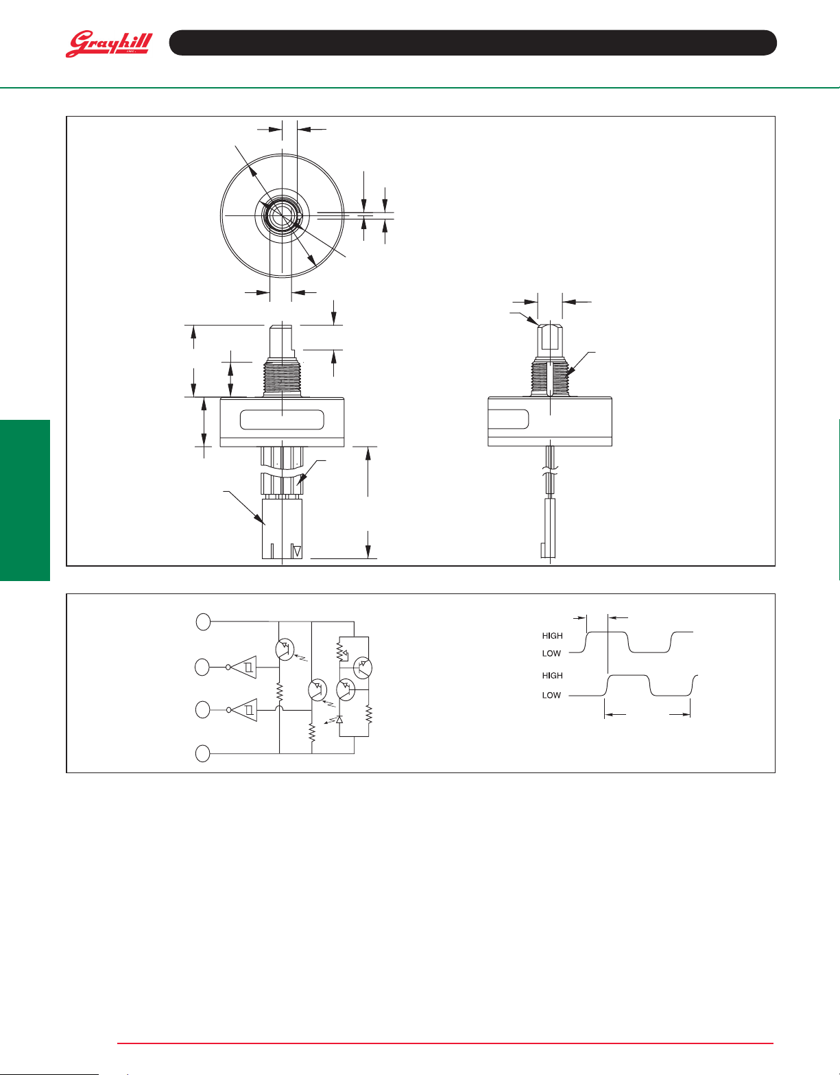
DIMENSIONS in inches (and millimeters)
Pin Version
1.250 DIA
(31.75)
.152
(3.86)
KEYWAY DEPTH
.033
(.84)
.066
(1.68)
Optical Encoders
Linear ± .010
Diameter ± .025
Angle ± 2.0°
Optical and Mechanical
Encoders
.725±.025
(18.4±2.64)
.501
(12.73)
.219
(5.57)
.350
(8.89)
.150
(3.81)
GRAYHILL XXXX X-X
61kXXX
.250
(6.35)
.100
(2.54)
.300
.550 DIA
(13.97)
MOUNTING
SURFACE
PIN #1
.776± .025
(19.7± 1.64)
.025 X 45˚
(.64)
CHAMFER
XXXX X-X
XX
.225
(5.71)
.249/.250 DIA
(6.32/6.34)
3/8 - 32
UNEF-2A
THREADS
Grayhi ll, Inc . • 5 61 H illgrove Avenue • LaGra nge, Illi nois 6 0525-5997 • U SA • P hone: 708 -354-1040 • Fax: 708 -354-2820 • www.gra yhill.com
Page 2
Optical Encoders
4
PIN #
POWER 5V
CLOCKWISE ROTATION OF SHAFT.
90 – 45
CONNECT
MOLEX P/N
14-56-3046
OR EQUIV
DIMENSIONS in inches (and millimeters)
Cable Version
.725± .025
(18.4± 2.64)
1.250 DIA
(31.75)
.219
(5.57)
.350
(8.89)
.152
(3.86)
KEYW AY DEPTH
.033
(.84)
.550 DIA
(13.97)
MOUNTING
SURF ACE
.250
(6.35)
.066
(1.68)
UNLESS OTHERWISE SPECIFIED, DIMENSION TOLERANCES ARE AS FOLLOWS:
LINEAR .010 (.25), DIAMETERS .010 (.25), ANGULAR 5˚
.249/.250 DIA
.025 X 45˚
(.64)
CHAMFER
(6.32/6.34)
3/8 - 32
UNEF-2A
THREADS
GRA YHILL XXXX X-X
61KXXX-XXX
Optical and Mechanical
PIN #1
CABLE LENGTH
4.000,25
(4.000, 7)
Encoders
.501
(12.73)
OR IS
ALENT
C IRCUITRY , TRUTH TABLE, AND WAVEFORM : Standard Quadrature 2-Bit Code
GROUND
OUTPUT B
OUTPUT A
1
2
10 KΩ
3
10 KΩ
SPECIFICATIONS
Electrical Ratings
Operating Voltage:
Supply Current:
Logic Output Characteristics:
Output Type: Open collector with
integrated Schmitt Trigger and 10K ohms pullup resistor Maximum Sink Current: 16 mA
at .40 volts
Power Consumption: 150 mW maximum
Optical Rise Time: 500 nS typical
Optical Fall Time: 16 nS typical
5.0 ±.25 Vdc
30 mA maximum at 5 Vdc
Mechanical Ratings
Mechanical Life: 10 million revolutions
me Life: Guaranteed for 10 years of continuous
Ti
operation (calculated from emitter degradation
data)
Mounting Torque: 20 in-lbs maximum
Shaft Push Out Force: 100 lbs
Terminal Strength: 5 lbs terminal pull-out
force minimum
Solderability: 95% free of pin holes and voids
Operating Torque: 1.5 in-oz maximum (no
detents) for unsealed versions
XXXX X-X
XX-XXX
OUTPUT
OUTPUT
A
B
1 CYCLE
CHANNEL A LEADS CHANNEL B BY
90 – 45 IN ALL ROTATIONS FOR
Environmental Ratings
Operating Temp
rage Tempera ture Range:
Sto
R
elative Humidity: 90-95% at 40°C for 96 hours
Vibration Resistance:
amplitude of 15g, within a varied 10 to 2000 Hz
frequency for 12 hours per MIL-STD-202, Method
204
Mechanical Shock: Test 1: 100g for 6 mS, half-sine
wave with velocity change of 12.3 ft/s. Test 2: 100g for
6 mS, sawtooth wave with velocity change of 9.7 ft/s.
erature Range:
Harmonic motion with
-
0°C to 85°C
-4
55°C to 100°C
Grayhi ll, Inc . • 5 61 H illgrove Avenue • LaGra nge, Illi nois 6 0525-5997 • U SA • P hone: 708 -354-1040 • Fax: 708 -354-2820 • www.gra yhill.com
Page 3

SERIES 61R
GRAYHILL XXXX X-X
61RXXX
XXXX X-X
XX
(31.75)
.219
(5.57)
.033
(.84)
.066
(1.68)
.250
(6.35)
.400
(10.16)
.200
(5.08)
.100
(2.54)
.501
(12.73)
.225
(5.71)
.249/.250 DIA
(6.32/6.34)
.025 X 45˚
(.64)
CHAMFER
3/8 - 32
UNEF-2A
THREADS
PIN #1
.350
(8.89)
.550 DIA
(13.97)
MOUNTING
SURFACE
.152
(3.86)
KEYWAY DEPTH
High Resolution, 5-Pin
(Polarized Connection)
FEATURES
• 25, 32, 50, 64, 100, 128 and 256
Cycles per Revolution Available
• Sealed Version Available
• Rugged Construction
• Cable or Pin Version
• 10 Million Rotational Cycles
• 300 RPM Shaft Rotation
• Index Pulse Available
DIMENSIONS in inches (and millimeters)
Optical Encoders
Pin Version
.725±.025
(18.4±2.64)
1.250 DIA
.776±.025
(19.7±1.64)
Unless otherwise specied, standard tolerance are:
Linear ± .010
Diameter ± .025
Angle ± 2.0°
Optical and Mechanical
Encoders
Grayhill, Inc. • 561 Hillgrove Avenue • LaGrange, Illinois 60525-5997 • USA • Phone: 708-354-1040 • Fax: 708-354-2820 • www.grayhill.com
Page 4

Optical Encoders
1 CYCLE
OUTPUT
A
OUTPUT
B
CHANNEL A LEADS CHANNEL B BY
90 – 45 IN ALL ROTATIONS FOR
CLOCKWISE ROTATION OF SHAFT.
90 – 45
1
2
3
5
4
10 KΩ
10 KΩ
PIN #
GROUND
NO CONTACT
OUTPUT A
POWER 5V
OUTPUT B
GRAYHILL XXXX X-X
61RXXX-XXX
XXXX X-X
XX-XXX
UNLESS OTHERWISE SPECIFIED, DIMENSION TOLERANCES ARE AS FOLLOWS:
LINEAR .010 (.25), DIAMETERS .010 (.25), ANGULAR 5˚
1.250 DIA
(31.75)
.219
(5.57)
.033
(.84)
.066
(1.68)
.250
(6.35)
.501
(12.73)
.350
(8.89)
.249/.250 DIA
(6.32/6.34)
.025 X 45˚
(.64)
CHAMFER
3/8 - 32
UNEF-2A
THREADS
CABLE LENGTH
6.000, 25
(6.000, 7)
CONNECTOR IS
MOLEX P/N
14-56-3056
OR EQUIVALENT
PIN #1
.550 DIA
(13.97)
MOUNTING
SURFACE
.152
(3.86)
KEYWAY DEPTH
DIMENSIONS in inches (and
Cable Version
Optical and Mechanical
Encoders
.725±.025
(18.4±2.64)
millimeters)
CIRCUITRY, TRUTH TABLE, AND WAVEFORM: Standard Quadrature 2-Bit Code
Mechanical Ratings
Mechanical Life: 10 million revolutions
Time Life: Guaranteed for 10 years of continuous
operation (calculated from emitter degradation data)
Mounting Torque: 20 in-lbs maximum
Shaft Push Out Force: 100 lbs
Terminal Strength: 5 lbs terminal pull-out force
minimum
Solderability: 95% free of pin holes and voids
Operating Torque: 1.5 in-oz maximum (no
detents) for unsealed versions
SPECIFICATIONS
Electrical Ratings
Operating Voltage: 5.0 ±.25 Vdc
Supply Current: 30 mA maximum at 5 Vdc
Logic Output Characteristics:
Output Type: Open collector with integrated
Schmitt Trigger and 10K ohms pull-up resistor
Maximum Sink Current: 16 mA at .40 volts
Power Consumption: 150 mW maximum
Optical Rise Time: 500 nS typical
Optical Fall Time: 16 nS typical
Grayhill, Inc. • 561 Hillgrove Avenue • LaGrange, Illinois 60525-5997 • USA • Phone: 708-354-1040 • Fax: 708-354-2820 • www.grayhill.com
Environmental Ratings
Operating Temperature Range: -40°C to 85°C
Storage Temperature Range: -55°C to 100°C
Relative Humidity: 90-95% at 40°C for 96 hours
Vibration Resistance: Harmonic motion with
amplitude of 15g, within a varied 10 to 2000
Hz frequency for 12 hours per MIL-STD-202,
Method 204
Shock Resistance: Test 1: 100g for 6 mS, halfsine wave with velocity change of 12.3 ft/s. Test
2: 100g for 6 mS, sawtooth wave with velocity
change of 9.7 ft/s.
Page 5

Optical Encoders
C
L
.125 ± .010
(3,16 ± 0,25)
.005 ± .003
(0,38 ± 0,08)
RADIUS
.032 ± .002
(0,81 ± 0,05)
90˚ ± 1˚
.625 ± .010 DIA.
(15,89 ± 0,25)
.120 ± .003
(3,05 ± 0,08)
.437 + .010 –.000
(11,10 + 0,25 –0,00)
.032
± .002
(0,81
± 0,05)
.110
± .003
(2,79
± 0,08)
.030 (0,76)
RADIUS MAX.
.625 ± .010
(15,88 ± 0,25) DIA.
.120 ± .003
(3,05 ± 0,08)
.530 ± .005
(13,46 ± 0,13)
90˚ ± 1˚
Materials and Finishes
Bushing: Aluminum
Code Housing: Zytel FR-50
Shaft: Stainless steel
Retaining Ring: Stainless steel
Code Rotor and Aperture: Chemically etched
stainless steel/electroformed nickel
Printed Circuit Board: NEMA Grade FR-4.
Five microinches minimum gold over 100
microinches minimum nickel over copper
ORDERING INFORMATION
61RS256 – 060
Optical Barrier: Polyphenylene sulde, 94
V-0
Backplate: Polyester
Header: Phosphor bronze, 200 microinches tin
over 50 microinches nickel (pin version only)
Infrared Emitter: Gallium aluminum arsenide
Photo IC: Planar silicon
Cable: 26 AWG, stranded/tinned wire, PVC
coated on .100 (2,54) centers (cable version
only)
Series
Style: K = Standard, 4-pin, high resolution
KS = Sealed, 4-pin, high resolution
R = Standard, 5-pin, high resolution
RS = Sealed, 5-pin, high resolution
Cycles: per channel per revolution = 25, 32, 50, 64, 100, 128, 256
Cable Termination: 060 = 6.0in. Cable is terminated with Molex Connector P/N 14-56-3056
Optical and Mechanical
Encoders
Available from your local Grayhill Distributor. For prices and discounts, contact a local Sales Ofce, an authorized local Dstributor or Grayhill.
ACCESSORIES
Non-Turn Washer
The Series 61 bushing is 3/8 inches in diameter
and has a non-turn keyway to prevent rotation of
the switch body when the panel is cut to t.
Another way to keep the switch from turning is to
use a non-turn washer. The washer is cadmiumplated brass.
Part number: 12C1087-1
Part number: SHH694-11, 302-2B stainless
steel, no plating
Shaft and Panel Seal
For shaft and panel seal version, the shaft is
sealed by an o-ring inside the bushing. The
panel is sealed by a at gasket .045" thick at
the base of the bushing. The panel seals will
increase the behind panel dimension by .020"
to .040", when the switch is mounted. The panel
seal is silicon rubber.
DIMENSIONS In inches (and millimeters)
Part Number: 12C1087-1
Grayhill, Inc. • 561 Hillgrove Avenue • LaGrange, Illinois 60525-5997 • USA • Phone: 708-354-1040 • Fax: 708-354-2820 • www.grayhill.com
Part Number: SHH694-11
 Loading...