

Page 1
Optical Encoders
Ø
1.000
25,4
[]
.460
11,68
[]
.642±.003
16,31±0,07
[]
Ø
PANEL SEAL I.D.
.750
19,05
[]
Ø
PANEL SEAL O. D.
.850
21,59
[]
.548
13,92
[]
.600
15,24
[]
SHAFT FLAT
.219±.002
5,56
±
0,05
[]
]
.940
±
.020
23,88
±
0,5[]
.610±.015
15,49
±
0,38[]
REF.
JOYSTICK
PIVOT POINT
.172
4,36[]
.853±.015
21,67
±
0,38[]
.932±.020
23,67±0,5[]
M17x1.0
THREAD
HEADER IS
SAMTEC P/N
ASP-120519-01
(.050" SPACING)
MOUNTING SURFACE
Ø
.250±.002
6,35
±
0,05[]
.250
6,35[]
.046±.015
1,17
±
0,38[]
.280
7,11[]
.020
0,51[
.338
8,59[]
.025x45°
[0,63]x45°
CHAMFER
PANEL SEAL GASKET NOT SHOWN IN LOWER
VIEWS TO ILLUSTRATE MOUNTING SURFACE
SCALE 2.000
.652
±
.003
16,56±0,07[]
.679±.003
17,25±0,07[]
Ø
PANEL SEAL GASKET NOT SHOWN TO ILLUSTRATE MOUNTING SURFACE
Ø
.250±.002
6,35
±
0,05[]
.250
6,35[]
.046±.015
1,17±0,38[]
.020
0,51[]
.280
7,11[]
.338
8,59[]
.025x45°
[0,63]x45°
CHAMFER
CABLE LENGTH
±.200
[±5,08]
.455
±
.015
11,56
±
0,38[]
.605
±
.015
15,37
±
0,38[ ]
.927
±
.020
23,55
±
0,5[]
REF.
JOYSTICK
PIVOT POINT
.172
4,36[]
.853
±
.015
21,67
±
0,38[]
M17x1.0
THREAD
CONNECTOR IS
AMP P/N 215083-8
OR EQUIVALENT
MOUNTING SURFACE
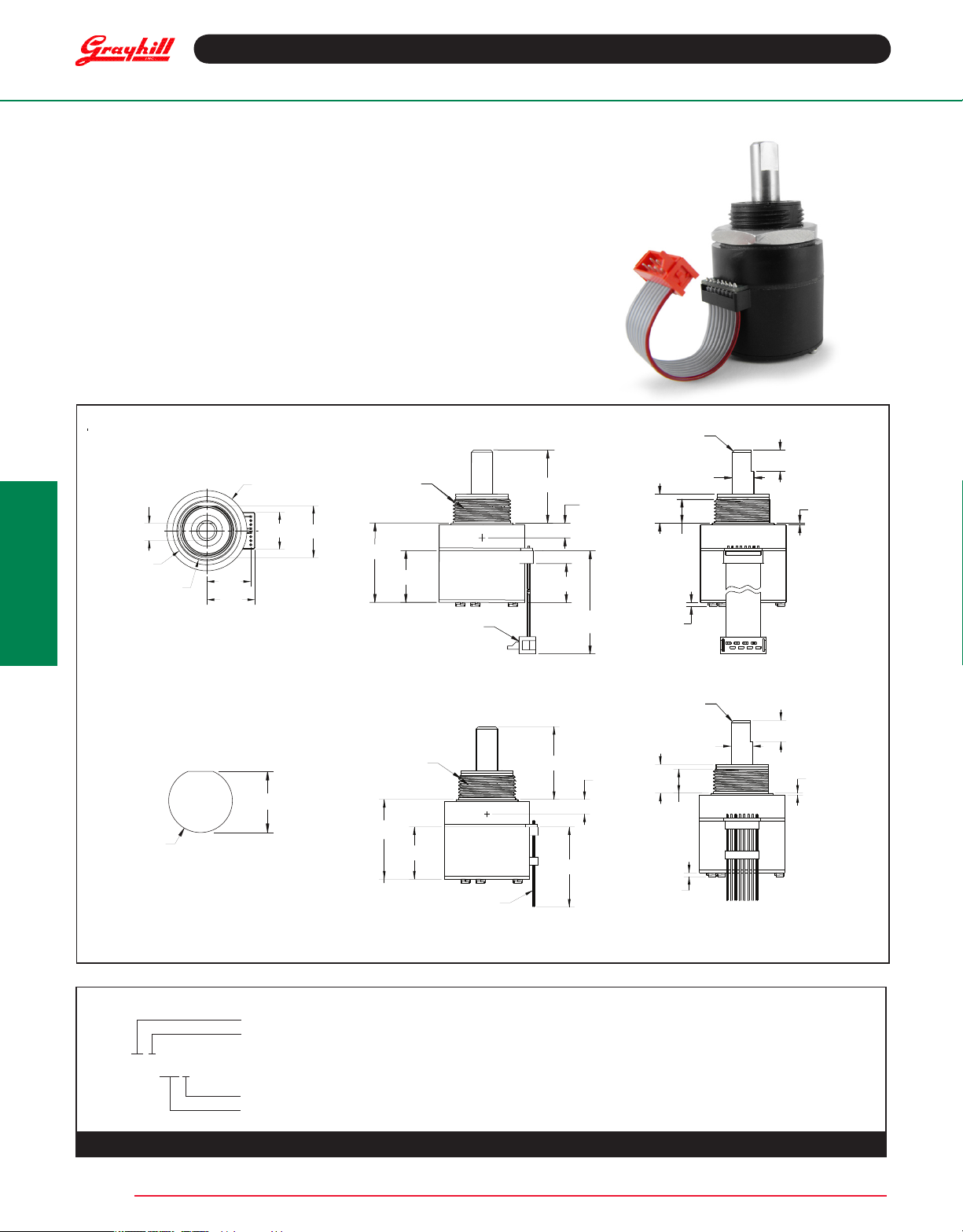
SERIES 60AR
Rugged and Sealed Joystick
FEATURES
• Three-in-One Joystick, Optical Encoder and Pushbutton
• Shaft and panel sealed to IP67 against liquids and particulates
• Choices of knobs, cable length and termination
• Customized solutions available
APPLICATIONS
• Aerospace
• Military vehicles and devices
• Mobile electronics for outdoor use
DIMENSIONS in inches (and millimeters)
Unless otherwise specied, standard tolerance are:
Linear ± .025
Diameter ± .010
Angle ± 2.0°
Cable Connector Version
Optical and Mechanical
Encoders
Recommended Panel Cut Out
Pin Version
ORDERING INFORMATION
Angle of Throw: 18= 18° or 20 positions, 08= Non-detent or 20 positions, 00= Non-turn
Joystick: 4= Four contacts & four directions; 8= Four contacts & eight directions
60AR18-4-060S
Termination: 0.050" center P= pin header; C= connector; S= stripped cable
Cable Length: 020 thru 250 in 1/2 inch increments, 060= 6.0 inch cable, leave blank if pinned
For prices and custom congurations, contact a local sales ofce, an authorized distributor, or Grayhill's sales department.
Grayhill, Inc. • 561 Hillgrove Avenue • LaGrange, Illinois 60525-5997 • USA • Phone: 708-354-1040 • Fax: 708-354-2820 • www.grayhill.com
Page 2
Optical Encoders
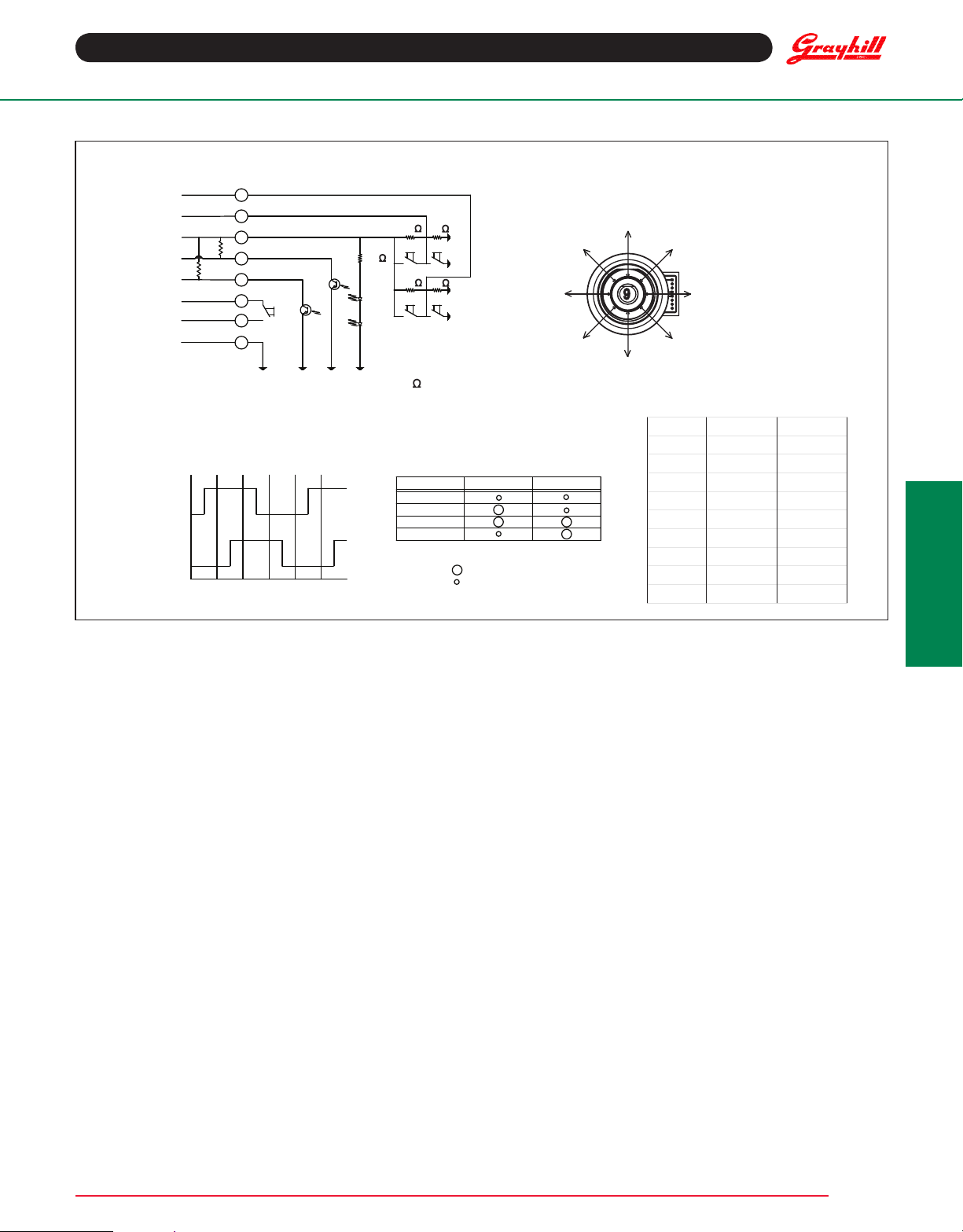
POSITION X OUTPUTY OUTPUT
12.5 HIGH
2HIGHHIGH
3HIGH2.5
4HIGHLOW
52.5 LOW
6LOW LOW
7LOW 2.5
8LOW HIGH
92.5 2.5
JOYSTICK
TRUTH TA BLE
HIGH
LOW
HIGH
LOW
OUTPUT A
OUTPUT B
POS.#1POS.#2POS.#3POS.#4POS.#5POS.
#6
ENCODER WAVEFORM
(C.W. ROTATION)
SWITCH SCHEMATIC
1
7
8
OUTPUT A
OUTPUT B
NORMALLY OPEN
PUSHBUTTON
SWITCH
GROUND
R
*
R
*
5
6
4
3
POWER +5.0V
JOYSTICK
Y DIRECTION
JOYSTICK
X DIRECTION
2
10k
10k
10k
10k
180
EXTERNAL PULL-UP RESISTORS REQUIRED FOR OPERATION (2.2k
).
*
JOYSTICK POSITION DIAGRAM
* INDICATES DIRECTION OF
D-FLAT ON BUSHING
5
1*
8
7
6
4
3
2
POSITION OUTPUT A OUTPUT B
#1
#2
#3
#4
INDICATES LOGIC-HIGH
INDICATES LOGIC-LOW
CODE REPEATS EVERY FOUR POSITIONS
ENCODER
TRUTH TA BLE
(C.W. ROTATION)
JOYSTICK OPERATION + ENCODER WAVEFORM AND TRUTH TABLE Standard Quadrature 2-Bit Code
SPECIFICATIONS
Environmental Specifications
Operating Temperature Range: -40oC to 85oC
Storage Temperature Range: -40oC to 100oC
Humidity: 96 hours at 90-95% humidity at 40oC
Mechanical Vibration: Harmonic motion with amplitude of 15g, within
a varied 10 to 2000 Hz frequency for 12 hours
Mechanical shock:
Test 1: 100g for 6Ms half sine wave with velocity change of 12.3 ft/s.
Test 2: 100g for 6 Ms sawtooth wave with velocity change of 9.7 ft/s.
Shaft and panel Seal: IP67, 1 meter submersion for 30 minutes
Joystick Electrical & Mechanical Specifications
Supply Current: 5 Ma, maxium
Output Code: 2-bit
Logic Output Characteristics: Neutral Position: 2.5±0.5 Vdc,
High-state Position: >4.5 Vdc, Low-state Position: <0.5 Vdc
Mechanical Life (Joystick): 500k actuations, minimum
in each direction
Actuation Force (Joystick): 1500±300g (X&Y directions only)
Angle of Throw: 3.5o+2/1o (X&Y directions only, at electrical contact)
Pushbutton Electrical & Mechanical Specifications
Rating: 10 Ma at 5 Vdc, resistive
Contact Resistance: Less than 10 Ω
Contact Bounce: <4 Ms make, <10 Ms break
Mechanical Life (Pushbutton): 1 million actuations, minimum
Actuation Force (Pushbutton): 1600±400g
Pushbutton Travel: .015±.005 in
Specifications are subject to change
Grayhill, Inc. • 561 Hillgrove Avenue • LaGrange, Illinois 60525-5997 • USA • Phone: 708-354-1040 • Fax: 708-354-2820 • www.grayhill.com
Rotary Electrical & Mechanical Specifications
Operating Voltage: 5.00±25 Vdc
Supply Current: 20 Ma, maximum at 5 Vdc
Minimum Sink Current: 2.0 Ma for 5 Vdc
Output: Open collector phototransister, external pull-up resistors
are required
Output Code: 2-bit quadrature, channel "A" leads channel "B"
by 90o electrically during clockwise rotation of the shaft
Logic Output Characteristics: Logic-high shall be no less than
3.5 Vdc, Logic-low shall be no greater than 1.0 Vdc
Optical Rise Time: 30 µs, maximum
Optical Fall Time: 30 µs, maximum
Mechanical Life (Rotational): 1 million cycles, minimum
(1 cycle is a rotation through all positions and a full return)
Average Rotational Torque: 8.0±30% in-oz, initial
Shaft Push-out Force: 60 lbs, minimum before failure
Shaft Side-load Force: 25 lbs, minimum before failure
Terminal Strength: 15 lbs pull-out force, minimum for cable
or header termination
Solderability: 95% free of pin holes or voids
Maximum Rotational Speed: 100 Rpm
Mounting Torque: 15 in-lbs maximum
Optical and Mechanical
Encoders
 Loading...