

Page 1

Before installing and using this
machine, you must read this user
guide carefully.
Keep it in a safe place, in case you
need to refer to it later.
E8147 703 - 09.2007 - ENG - (UPDATED EDITION NUMBER : 3)
(
Please read carefully before use
User manual
L-SOLUTION
700 / 800 / 900
Machines
LASER engraving machines
First contact
)
Page 2
TYPE OF MACHINE : L-SOLUTION 700 / 800 / 900 LASER ENGRAVING MACHINES
MANUFACTURER : GRAVOGRAPH INDUSTRIE INTERNATIONAL
This publication and its contents are proprietary to Gravograph Industrie International (Gravograph), and are intended
solely for the contractual use of Gravograph customers.
While reasonable efforts have been made to assure the accuracy of this manual, Gravograph shall not be liable for errors
contained herein or for incidental or consequential damage in connection with the furnishing, performance, or use of this
material.
Gravograph reserves the right to revise this manual and make changes from time to time without any obligation by
Gravograph to notify anybody of such revision or changes.
Gravograph can not be held liable for any problems arising out of the application or use of any products, circuits, or software
described herein. Neither does it convey a license under its patent rights nor the patent rights of third parties.
BP 15 - Z.I. - 10600 LA CHAPELLE SAINT LUC - FRANCE
Importer's address
Gravograph provides no warranties whatsoever on any software used in connection with a Gravograph Laser Engraving
System, express or implied. Neither does it guarantee software compatibility with any off-the-shelf software package or
any software program that has not been written by Gravograph.
Intended use of this system must be followed within the guidelines of this manual. In no event will Gravograph be liable
for any damages caused, in whole or in part, by customer, or for any economic loss, physical injury, lost revenue, lost profits,
lost savings or other indirect, incidental, special or consequential damages incurred by any person, even if Gravograph has
been advised of the possibility of such damages or claims.
Windows is a registered trademark of Microsoft Corporation.
PostScript is a registered trademark of Adobe Systems Inc.
(c) Gravograph Industrie International, 2005
All Rights Reserved.
L-SOLUTION 700 / 800 / 900 machines . 2
First contact
Page 3

Summary
Regulatory information ....................................................................... 5
Compliance standards ...................................................................................................................... 5
Electrical security ............................................................................................................................ 5
Overview ............................................................................................ 6
Introduction ................................................................................................................................... 6
Contra-indications ........................................................................................................................... 6
Unpacking stages ............................................................................................................................ 8
Unpacking - Package contents ........................................................................................................... 9
LASER safety ................................................................................................................................ 10
Description ....................................................................................... 13
Front view of the machine .............................................................................................................. 13
Rear view of the machine ............................................................................................................... 14
Installation ....................................................................................... 15
Physical installation recommendations .............................................................................................. 15
Exhaust system installation recommendations ................................................................................... 17
Air-assist requirements (compressor optional) ...................................................................................17
Computer requirements ................................................................................................................. 18
Software suggestions ..................................................................................................................... 18
Font requirements ......................................................................................................................... 18
Electric installation recommendations ............................................................................................... 19
Electrical connections of the machine ............................................................................................... 21
Powering the machine on ............................................................................................................... 22
Problems ...................................................................................................................................... 22
Powering the machine off ............................................................................................................... 22
Mechanical jamming ...................................................................................................................... 22
Powering on again ......................................................................................................................... 22
Setting up transmission between the L-SOLUTION (700 / 800 / 900)
machine and a PC type computer ...................................................... 23
Connection cables ......................................................................................................................... 23
Connecting L-SOLUTION to your PC using the USB port ...................................................................... 24
Connecting L-SOLUTION to your PC using the parallel port .................................................................. 25
Connecting L-SOLUTION to your PC using the serial port (only with the old machines) ............................ 26
Machine setup (language)............................................................................................................... 27
The printer driver of the LASER machine........................................... 29
How the computer controls the LASER machine ................................................................................. 29
Installing the Windows® (Windows 2000®, XP® or 98®) driver ......................................................... 30
Driver controls .............................................................................................................................. 43
Graphics software ............................................................................. 64
Software setup .............................................................................................................................. 64
Speed optimization ........................................................................................................................ 65
Bitmapped / scanned images .......................................................................................................... 65
First contact
L-SOLUTION 700 / 800 / 900 machines . 3
Page 4

System operation .............................................................................. 66
How it works ................................................................................................................................ 66
The control panel ......................................................................................................................... 69
The engraving menu ..................................................................................................................... 72
Engraving menu description ........................................................................................................... 75
Automaton function (user standard Inputs/Outputs) .......................................................................... 82
Running the machine step by step .................................................... 83
Powering on ................................................................................................................................ 83
Creating the graphic ..................................................................................................................... 83
Setting the drivers' properties ........................................................................................................ 83
Downloading the file ..................................................................................................................... 83
Positioning the plate ..................................................................................................................... 84
Focusing the LASER beam ............................................................................................................. 84
Starting the engraving process ....................................................................................................... 85
Removing and reloading the material .............................................................................................. 86
Problems and solutions ................................................................................................................. 87
Options and accessories.................................................................... 88
Cylinder attachment ..................................................................................................................... 88
Stand of slant for cylinder attachment ............................................................................................. 88
Cutting kit ................................................................................................................................... 88
Compressor kit (air assist) ............................................................................................................. 89
Honeycomb cutting table ............................................................................................................... 89
Materials for LASER engraving .......................................................... 90
Safety ......................................................................................................................................... 90
Printer driver setting tips ............................................................................................................... 91
List of materials for LASER engraving .............................................................................................. 91
General maintenance ........................................................................ 92
Suggested cleaning and maintenance supplies .................................................................................. 92
System cleaning ........................................................................................................................... 93
Optics cleaning ............................................................................................................................ 95
Maintenance schedule ................................................................................................................... 95
Autofocus adjustment ................................................................................................................... 96
"Tickle" adjustment ...................................................................................................................... 99
Technical characteristics ................................................................. 102
Physical characteristics ................................................................................................................. 102
Electrical characteristics ............................................................................................................... 103
Firmware and driver characteristics ................................................................................................ 103
Optional accessories .................................................................................................................... 103
L-SOLUTION 700 / 800 / 900 machines . 4
First contact
Page 5
Regulatory
Regulatory information
Compliance standards
This hardware was designed and built in compliance with the relevant EC marking and EEC directives :
• "Security" Directive 98/37/EEC (22/06/98).
• "Electromagnetic compatibility" Directive 89/336/EEC (03/05/89) (modified)
• "Low voltage" Directive 73/23/EEC (modified)
Any change or transformation made to this equipment, any adaptation or installation
of accessories not recommended by GRAVOGRAPH, any installation of this equipment
in a manufacturing process, any piloting by a robot, any connection to an external
automaton, any change to the characteristics of this material, can make it become noncompliant with the European Directives it is subjected to.
Such changes void the manufacturer's responsibility.
In this case, the person who fits the machine and the equipment is responsible for the
EC compliance of the final work station.
Electrical security
This hardware complies with standards EN 60204-1 and EN 60950, which also refer to the LASER system safety standard
CEI 825-1 (08/2001).
Machine security
This hardware complies with standards EN 292-1, EN 292-2 and EN 12626.
Electromagnetic compatibility
This hardware complies with the following electromagnetic compatibility standards:
• EN 55022 - class A
• EN 61000-3-2
• EN 61000-3-3
• EN 61000-6-2 (immunity in an industrial environment)
This is a class A product. In a domestic environment this product may cause radio
interference in which case the user may be required to take adequate measures.
Electrical security
This material is «class 1». The mains plug MUST always be connected to a neutral
socket and comply with the regulations in force in the country of installation. If you
do not have a plug of this type, have one installed by an approved electrician. Under
no circumstances should you depart from this instruction.
The manufacturer bears no responsibility towards any user where alterations have been carried out contrary to the
manufacturer's specifications, notably with respect to electrical/electronic elements.
Any operation, other than those mentioned here, must only be carried out by an
approved Gravograph technician.
Do not take the machine apart to repair or clean it : this will void your guarantee.
First contact
This symbol indicates that once this equipment has reached the end of its useful life,
it must not be disposed of with non-sorted municipal waste, in accordance with the
European Directive 2002/96/EC.
The equipment must be disposed of at an appropriate collection point for processing,
sorting, and recycling of Waste Electrical and Electronic Equipment (DEEE).
The elements which compose Electrical and Electronic Equipment may contain
substances which have harmful effects on the environment or on human health.
By following these instructions, you are helping the environment, contributing to the
preservation of our natural resources, and protecting human health.
L-SOLUTION 700 / 800 / 900 machines . 5
Page 6
Overview
Overview
Introduction
Thank you for purchasing the L-SOLUTION machine. Years of testing and refinements have made this unit the ultimate
LASER engraving and cutting system.
Thanks to its innovative design with :
- the "F-load" Front loading concept developed to allow for the front loading of the plates and items to engrave,
- the "A-sens" Auto sensor concept, which adjusts the focal length automatically for you according to the surface
to be worked on (even when engraving a hollow item),
- the "D-fit" Depth fitting concept which calculates and adjusts the position of the LASER head automatically when
cutting thick materials in several passes,
- the beam concentration with the "X-beam" eXpanding beam concept designed to produce perfect quality
engraving over the entire surface of the table,
and with its performance results (speed, power and engraving areas), the L-SOLUTION combines flexibility and full featured
performance without sacrificing simplicity, ease of use, or ease of maintenance.
Using advanced engineering and design features, the L-SOLUTION is truly one-of-a-kind.
Actually, the L-SOLUTION is such a breakthrough in technology that it is more than just a LASER system, it is a precision
engraving and cutting device used as a tool for the imagination.
To begin with, we highly recommend that this entire manual be read before attempting to use the LASER system. The
manual includes important information about safety, assembly, use, and maintenance.
Contra-indications
Do not use the controls or settings and do not carry out procedures other than those
specified in the use manual, to avoid risking exposure to dangerous radiation.
The machine must never be handled without an adult present. Keep the machine,
wires and cables out of children's reach.
This machine is only designed for one user. Do not let several people use the machine
simultaneously.
The LASER engraving machine is a high performance machine : All safety instructions
must be complied with.
Exposure to the LASER beam may cause physical burns or severe eye damage. Proper
use and care of this system are essential to safe operation.
This machine is only designed for engraving and cutting purposes of the materials
listed in this user manual and must never be used for other applications.
The LASER machine must be properly installed and connected to an appropriate
discharge system in accordance with the specifications defined in this manual.
Do not use this machine in an explosive environment.
The processing materials must be introduced entirely into the machine.
Never expose yourself to the LASER beam. It could cause severe physical burns and
irreparable eye damage.
L-SOLUTION 700 / 800 / 900 machines . 6
First contact
Page 7
Overview
Never operate the LASER system without the machine protective casing.
Never operate the LASER system if the doors are in bad condition or can not be closed
properly.
Never operate the LASER system without constant supervision of the cutting and
engraving process.
Exposure to the LASER beam may cause ignition of combustible materials and start a
fire. A properly maintained fire extinguisher should be kept on hand at all times.
Never operate the LASER machine without a properly configured, installed, maintained,
and operating fume/smoke exhaust system.
Fumes and smoke from the engraving process must be extracted from the LASER
system and exhausted outside.
Never engrave or cut with LASER materials which may produce toxic and corrosive
fumes. DISCONTINUE processing any material that shows signs of chemical
deterioration of the LASER system (Systems damaged from this abuse will NOT be
covered under warranty).
We suggest that you obtain the Material Safety Data Sheet (MSDS) from the materials
manufacturer. The MSDS discloses all of the hazards that may arise from handling or
processing that material. The law requires all manufacturers to provide this information to anyone who requests it.
DO NOT ENGRAVE OR CUT PVC (Polyvinylchloride) BASED MATERIALS. The fumes are
extremely toxic if you inhale them. The fumes are so corrosive that they can chemically
destroy the metallic parts of the LASER system. Damage to the LASER system from this
type of abuse WILL NOT be covered under warranty.
Never work on the electronics and LASER parts of the machine without having
unplugged the machine, as hazardous voltages are present.
Although access to these areas is not necessary during normal use, should you need
to open one of these enclosures for service reasons, please remember to unplug the
machine first.
Never move or lift the LASER machine without the assistance of one (or three) person.
(176.4 to 375 lb - 80 to 170 kg). Severe bodily injury may occur if improper lifting
techniques are applied.
Be careful not to drop the LASER system. Not only can it cause bodily harm, but it can
also severely damage the equipment and render it inoperable.
Do not move, push, press on, or shake the LASER machine while the engraving is in
progress. This might shove the engraving part aside and make the engraving
unsuccessful.
Do not connect this equipment to an IT power supply card.
• If the machine is to remain unused for a long period, unplug the power supply and cover the machine (packaging, cover,
lid, etc.)
• Do not move the focus carriage holder manually except in case of a mechanical jamming of the machine, as described
in the paragraph entitled "Mechanical jamming" in this manual's "Installing" chapter.
• Do not spill any liquids onto the machine (drinks, cleaning fluids, etc.) unless recommended by GRAVOGRAPH (e.g. for
lubrication).
• If the engraving process must be stopped, use the function key provided for this purpose on the keyboard of the machine.
First contact
L-SOLUTION 700 / 800 / 900 machines . 7
Page 8
Unpacking stages
This machine should only be transported in its packaging and using a lifting apparatus
able to carry loads of least 661 lb (300 Kg).
After opening the box:
1. Loosening and removing the strap.
2. Remove the guards.
Unpacking of the L-SOLUTION 700 machine must be done by two people.
It weighs 176.4 lb (80 kg).
Unpacking of the L-SOLUTION 800 machine must be done by four people.
It weighs 331 lb (150 kg).
Unpacking of the L-SOLUTION 900 machine must be done by four people.
It weighs 375 lb (170 kg).
3. One (or two) person(s) on each side, lower the machine.
Make sure that no components are missing from the packaging. If any part has been
forgotten please get in touch with your GRAVOGRAPH dealer.
Unpacking
Keep all the packaging materials so that you can move your machine in total safety.
This packaging complies with European recycling standards.
L-SOLUTION 700 / 800 / 900 machines . 8
First contact
Page 9
Unpacking - Package contents
Check the condition of the packaging when you receive it. If there are any signs of
damage, inform the carrier and your GRAVOGRAPH dealer immediately by recorded
delivery, specifying the exact nature of the problem.
Unpacking
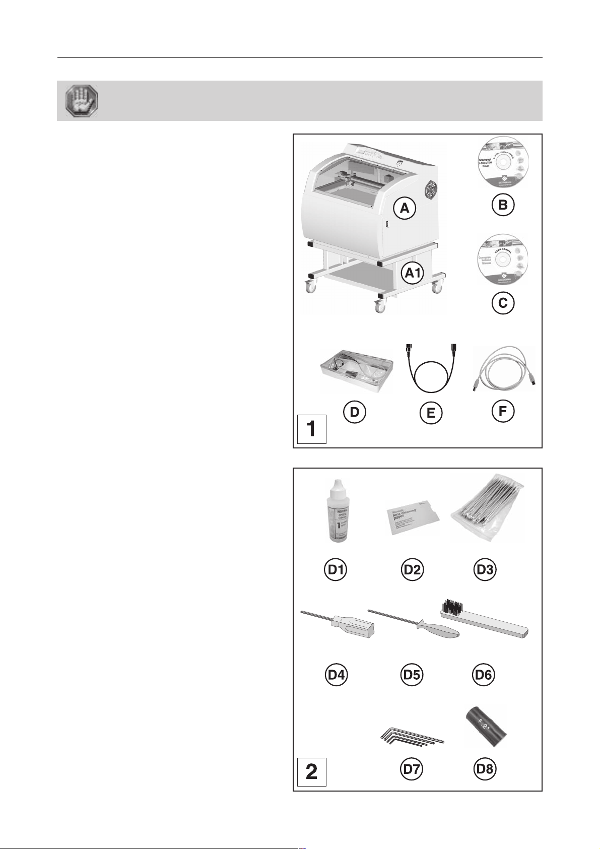
Package contents
(pict. 1)
A. An L-SOLUTION machine (700, 800 or 900)
((A1) support is optional for the
L-SOLUTION 800 and 900)
B. A CD-Rom contains the driver of the LASER
machine
C. A CD-Rom contains the user manual
(PDF file - Acrobat Reader)
D. A tool box
E. A power cable
F. An USB connection cable
L-SOLUTION 800
Tool box contents
(pict. 2)
D1. a lens/mirror cleaning solution
D2. a lens cleaning paper
D3. cotton swabs
D4. a short allen key
D5. a round allen key
D6. a brush
D7. four keys ...
D8. a wedge for Autofocus adjustment
First contact
L-SOLUTION 700 / 800 / 900 machines . 9
Page 10
LASER safety
LASER safety
This LASER machine contains a sealed carbon dioxide (CO2) LASER that produces
intense and invisible LASER radiation at a wavelength of 10.6 microns (µm)
(0.417 10-6 inch) in the infrared spectrum.
This LASER system contains a CO2 LASER in a Class I enclosure. However, due to the
presence of a visible red LASER diode (power < 1mW), the entire LASER system is
classified as Class 2.
- The entire system is completely enclosed with a protective housing. This will completely contain the invisible C02 LASER
beam under normal use. However, the red diode LASER is a visible LASER beam. DO NOT STARE INTO THE BEAM
OR VIEW DIRECTLY WITH OPTICAL INSTRUMENTS.
- The user door(s) are safety interlocked and will disable the CO2 LASER beam from firing when the user door(s) are opened.
The red diode LASER beam is NOT safety interlocked and can be activated with the door(s) either open or closed.
Do not modify or disable any safety feature of this system. Do not operate any system
that has had its safety features modified, disabled, or removed.
Improprer use of controls and adjustments, or performance of procedures other than
those specified in this manual, may invalidate the safety of this system.
CDRH and EC regulations require all LASER manufacturers to affix warning labels in specific locations throughout the
equipment.
The following warning labels are placed on the LASER system for your safety. DO NOT
remove them for any reason. If the labels become damaged or have been removed for
any reason, DO NOT OPERATE the LASER system and immediately contact Gravograph
for a free replacement.
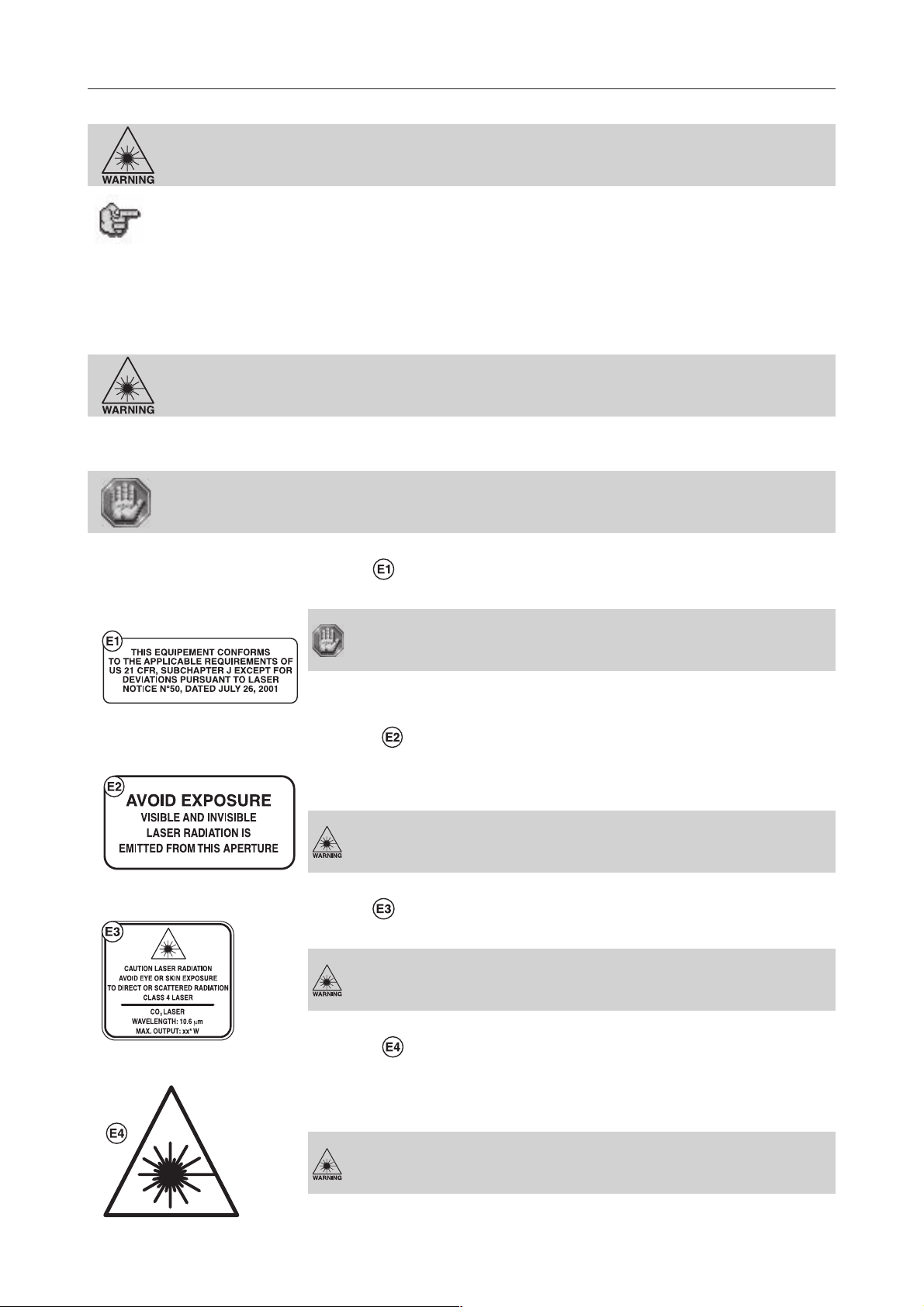
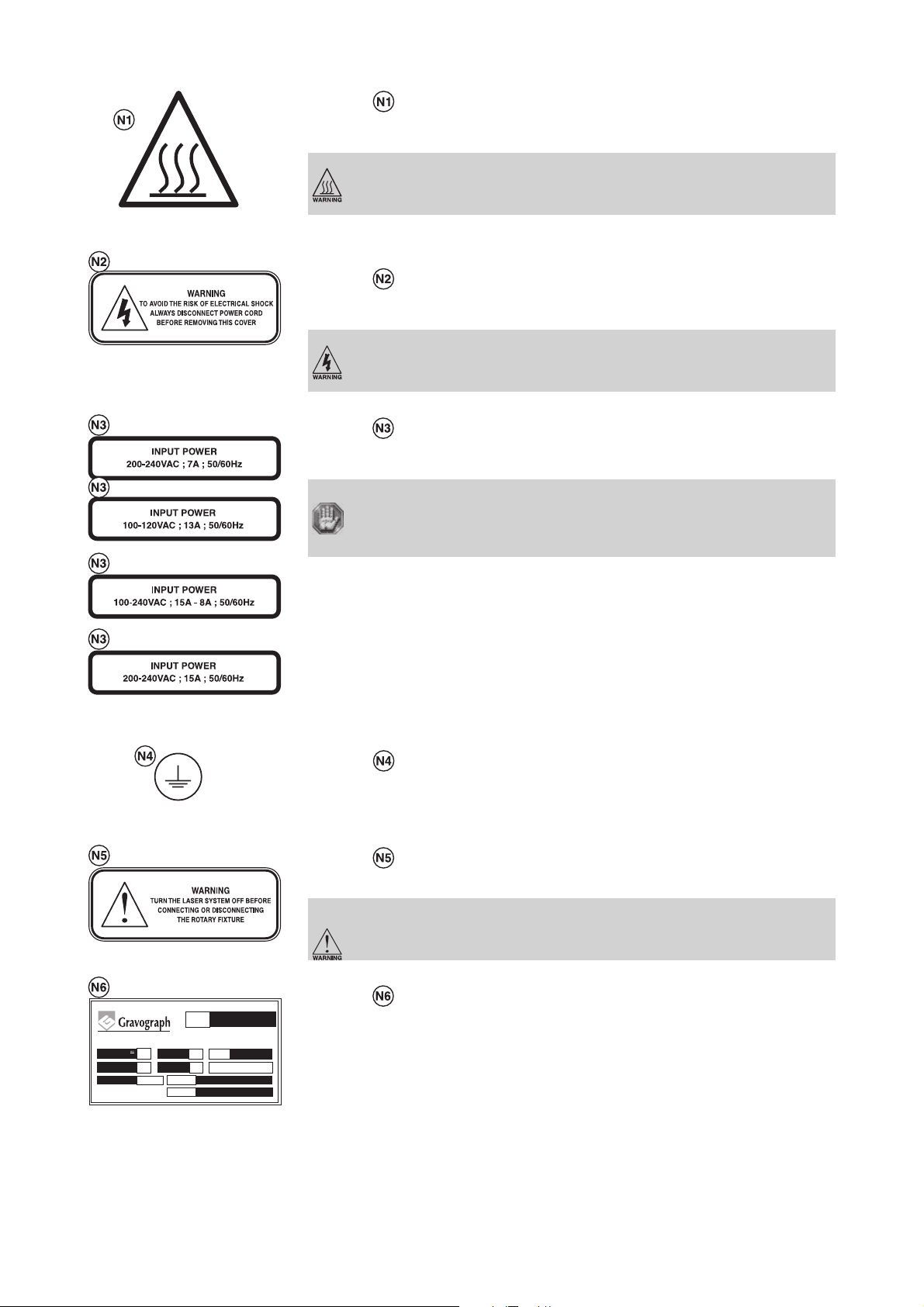
1 label :
On the back of the system next to the serial number tag. Visible when viewing the LASER system from the backside.
This machine is in compliance with American 21 CFR standards,
subchapter J except for deviations pursuant to LASER notice N° 50,
dated July 26, 2001.
2 labels :
One is next to the beam window where the LASER beam enters the engraving area inside the LASER system and
is visible when the front door is opened.
The second one is located on the LASER source where the LASER beam comes out. It is not visible under normal
operating conditions.
AVOID EXPOSURE - Visible and invisible LASER radiation is emitted
from this aperture.
1 label :
On the LASER tube assembly. Not visible under normal operating conditions.
CAUTION LASER RADIATION.
Avoid eye or skin exposure to direct or scattered radiation.
Class 4 LASER - CO2 LASER - Wavelength : 10,6µm (0.417 10-6 inch)
- Max. output : 100W.
4 labels :
One is next to the beam window where the LASER beam enters the engraving area inside the LASER system and
is visible when the front door is opened.
The second one is on the right, on the #1 mirror cover.
The third one is located on the LASER head next to the access hole of the #2 mirror.
The fourth one is located on the buse of the head.
L-SOLUTION 700 / 800 / 900 machines . 10
DANGER - Invisible and visible LASER radiation is present at that
place. Avoid eye or skin exposure to direct or scattered radiation.
First contact
Page 11
LASER safety
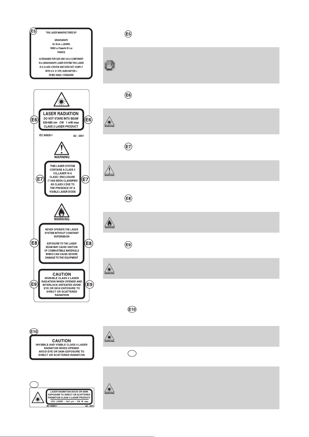
1 label :
On the LASER tube assembly. Not visible under normal operating conditions.
This LASER is manufactured by
GRAVOGRAPH
50-56 avenue J. JAURES - 10600 La Chapelle St Luc - FRANCE.
It is designed for use only as a component in a GRAVOGRAPH LASER
system.
This LASER is a class 4 device and does not comply with U.S. code 21
CF subchapter J, or European standard EN 60825-1.
1 label :
On the outside of the front door. Visible from the outside under normal operating conditions with the door closed.
CAUTION LASER RADIATION.
Do not stare into beam.
Wavelength : 630-680 nm (25 10-9 - 27 10-9 inch) - Max. output :
1mW.
Class 2 LASER product.
1 label :
On the outside of the front door. Visible from the outside under normal operating conditions with the door closed.
WARNING.
This LASER system contains a CO2 class4 LASER in a class I enclosure. It has been classified as class 2 due to the presence of a visible
LASER diode.
1 label :
On the outside of the front door. Visible from the outside under normal operating conditions with the door closed.
WARNING.
Never operate the LASER system without constant supervision.
Exposure to the LASER beam may cause ignition of combustible
materials which can cause severe damage to the equipment.
1 label :
One is on the front door and visible under normal operating conditions.
CAUTION - Invisible class 4 LASER radiation if open and the lock is
disabled. Avoid exposing the skin or eyes to direct or diffuse
radiation.
2 labels :
Inside the LASER system, on the machine protective casing on the left and on the right of the Y-Rails. Visible from
the outside under normal operating conditions with the door opened.
CAUTION.
Invisible and visible class 4 LASER radiation when opened. Avoid
eye or skin exposure to direct or scattered radiation.
E11
First contact
2 labels
Inside the LASER system, on the machine frame on the left and on the right of the Y-Rails.
E11
:
This label must not be visible under normal operating conditions
(machine with casing).
CAUTION.
LASER radiation. Avoid all skin exposure to direct or scattered
radiation. Class 4 LASER product.
CO2 LASER - Wavelength : 10,6µm (0.417 10-6 inch) - Max.
output : 100W
L-SOLUTION 700 / 800 / 900 machines . 11
Page 12
LASER safety
1 label :
On motor Y guard ( on bridge X on the right). Visible from the outside in normal operating conditions when in front
of the machine.
To avoid all risk of being burned do not touch the guard.
1 label :
One is on the back of the LASER machine next to the plug receptacle. Visible from the outside under normal operating
conditions when viewed from the backside of the system.
WARNING.
To avoid any risk of electrical shock, always disconnect the power
cord before removing this cover.
LASER 10W/20W
or
LASER 25W/30W/40W
LASER 60W/80W
1 label :
On the left back side of the LASER machine and next to the plug receptacle. Visible from the outside under normal
operating conditions.
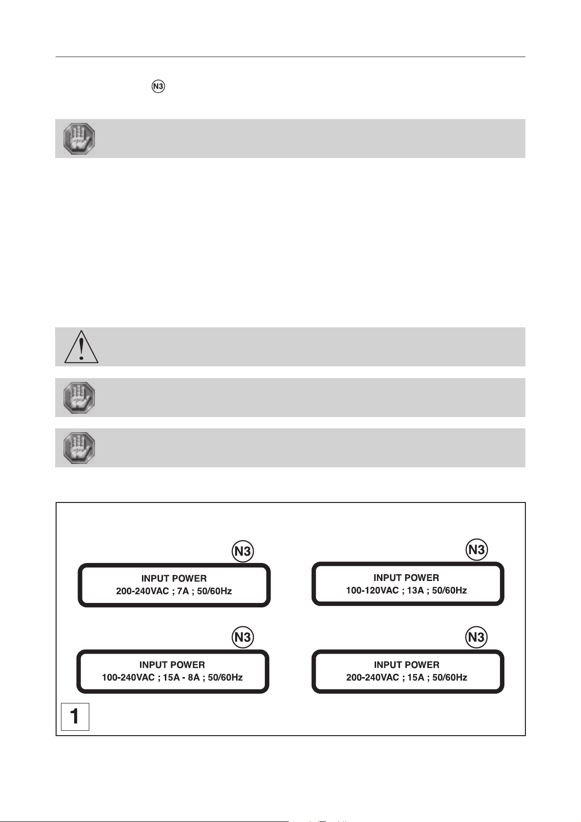
Electrical power supply :
LASER 10/20W :200-240 V (VAC) ; 7A ; 50-60 Hz
or 100-120 V (VAC) ; 13A ; 50-60 Hz
LASER 25/30/40W :100-240 V (VAC) ; 15A-8A ; 50-60 Hz
LASER 60/80W :200-240 V (VAC) ; 15A ; 50-60 Hz
1 label :
Inside the LASER system's power supply cover next to the chassis ground green wire. Not visible under normal
operating conditions. Visible only when cover is removed for maintenance only.
1 label :
Next to the cylinder attachment connector. Visible under normal operating conditions.
WARNING.
Turn the LASER system off before connecting or disconnecting the
cylinder attachment (rotary fixture).
1 label :
CE
06/01
10600 La Chapelle Saint Luc FRANCE
V
200-240
W
1300
20W
/mn
50/60
7
Service
N° Ser.
Hz
TYPE
A
CLASSE 1
S1
000000/0601
LS 800
On the rear side of the LASER system on the right when viewing the machine from the rear. Visible under normal
operating conditions.
L-SOLUTION 700 / 800 / 900 machines . 12
First contact
Page 13
Description
Description
The L-SOLUTION machine is a LASER engraving machine.
It has a control panel with a L.C.D. screen connected to the software in the machine.
Files to be engraved are transferred from the computer to the machine via a cable which is plugged into one of the two ports
on the L-SOLUTION machine.
The actual engraving process is controlled by a LASER.
The object to be engraved is placed on a table (as standard) or held by any other system recommended by GRAVOGRAPH
(consult your GRAVOGRAPH dealer for more information on systems available).
The L-SOLUTION machine has a maximum engraving surface area of:
- 12" x 12" (305 x 305 mm) (L-SOLUTION 700).
- 24" x 12" (610 x 305 mm) (L-SOLUTION 800).
- 24" x 24" (610 x 610 mm) (L-SOLUTION 900).
The L-SOLUTION LASER engraving machine is a high performance machine: All safety
instructions must be complied with.
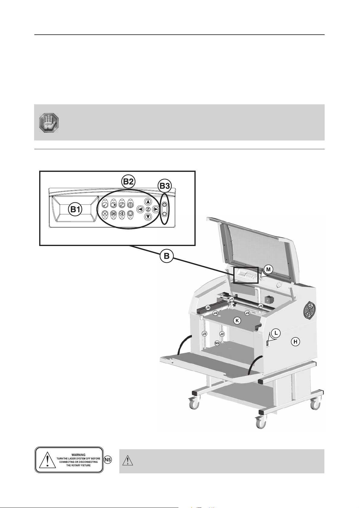
Front view of the machine
LASER engraving machine
(diagram 1)
H. Base
K. Engraving table
L. Main stop button
B. Control panel
B1. L.C.D. screen
B2. 12-key control keyboard
B3. 2 indicator lights (red and green)
M. Air-assist adjustment button
J1. Head
J2. Thread columns for the rise-lower moving
J3. Graduated X-ruler
J4. Graduated Y-ruler
J5. X-Rail
J6. Y-Rails
N9. Cylinder attachment connection (optional accessory)
L-SOLUTION 800
First contact
The machine must always be switched off before connecting or
disconnecting a cable or the cylinder attachment (optional
accessory), as indicated on label(N5).
L-SOLUTION 800 machine . 13
Page 14
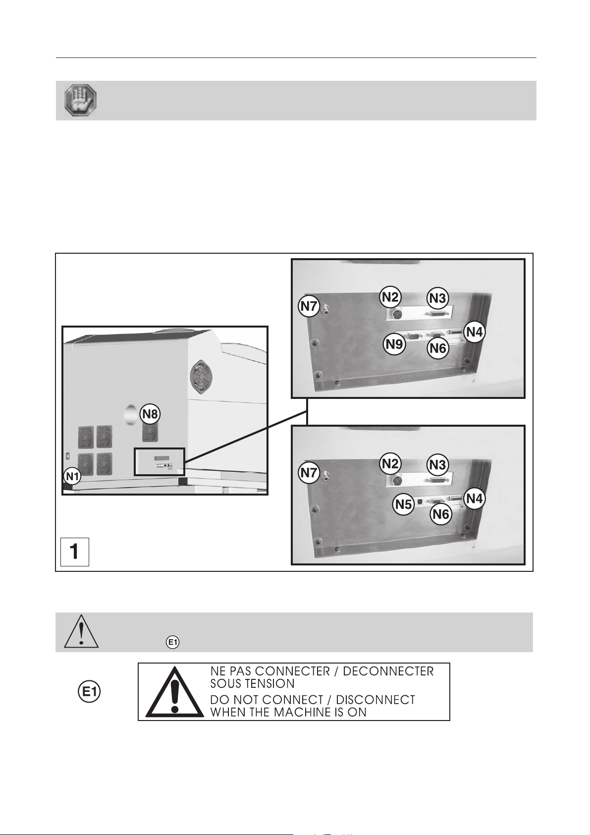
Rear view of the machine
Each connection responds to one of the following security levels :
- Dangerous voltage.
- Very low security level.
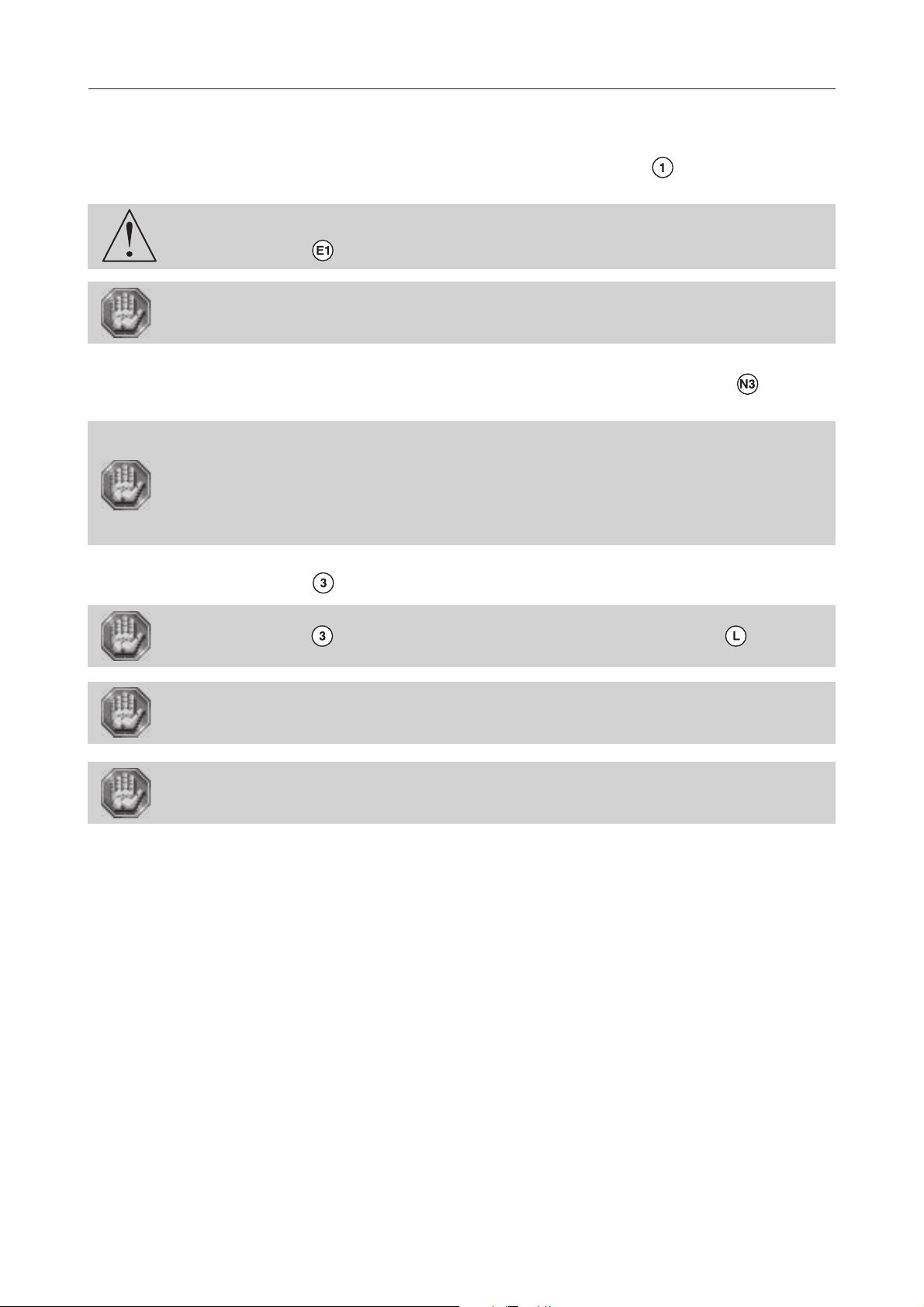
N. Connection socket (diagram 1)
N1 - Mains supply plug - Dangerous voltage
N2 - Exhaust system Inputs /Outputs - Very low security level
N3 - Standard Inputs /Outputs - Very low security level
N4 - Parallel port - Very low security level
N5 - USB port - Very low security level
N6 - Do not use (the protection cap is not to be removed for any reason)
N7 - Pneumatic supply for the air assist
N8 - Hole for the air evacuation pneumatic tube to the exhaust system.
N9 - Serial port (old machines) - Very low security level
Description
Old machines
L-SOLUTION 800
OR
New machines
The machine must always be switched off before connecting or disconnecting a cable
or the cylinder attachment (optional accessory), as indicated on
label :
L-SOLUTION 800 machine . 14
First contact
Page 15
Installation
Installation
Physical installation and electrical installation (connections) must only be carried out
by an approved GRAVOGRAPH technician.
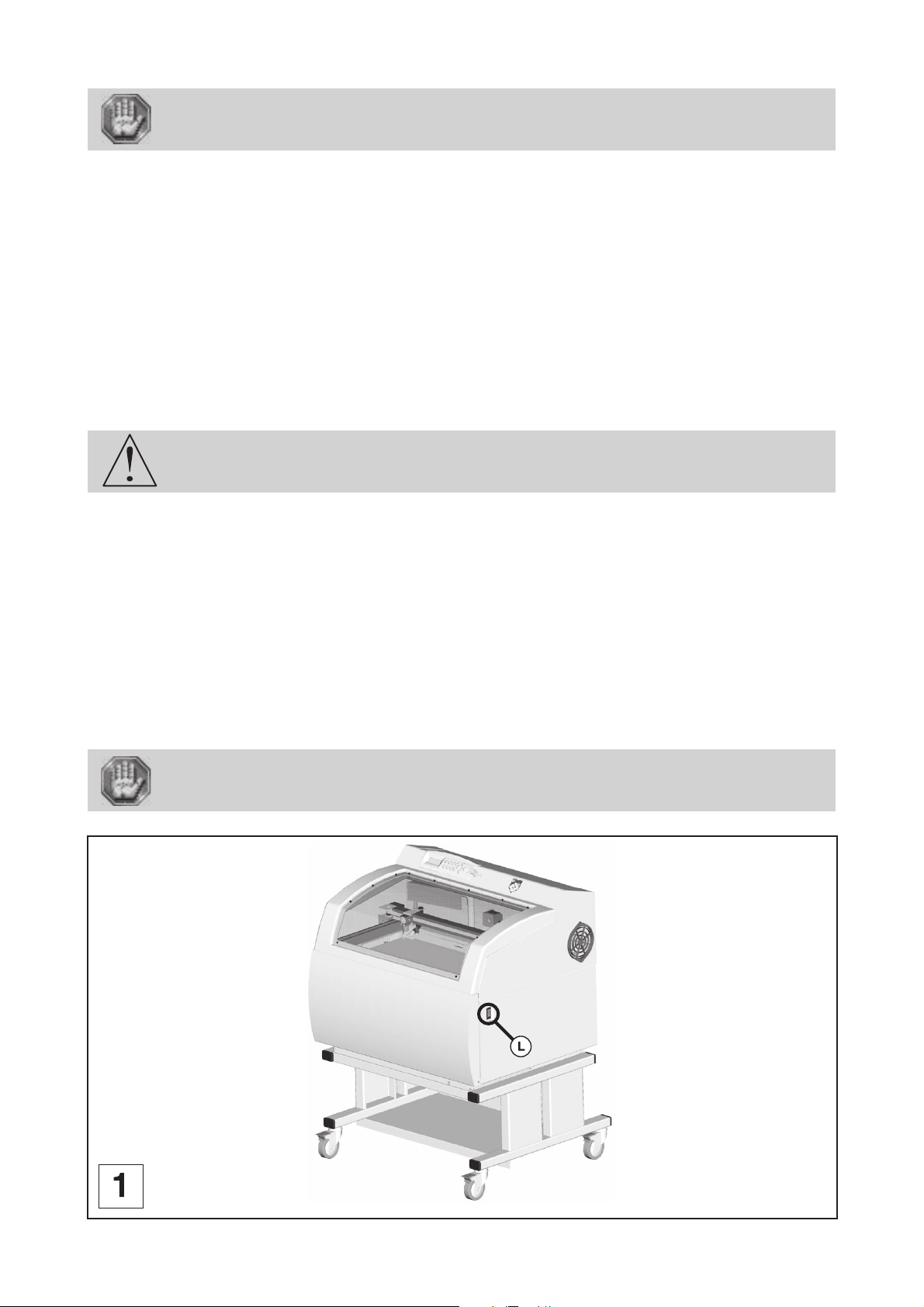
Before carrying out the following operations, make sure the machine is switched off
and unplugged, switch (L) to position 0 (pict. 1).
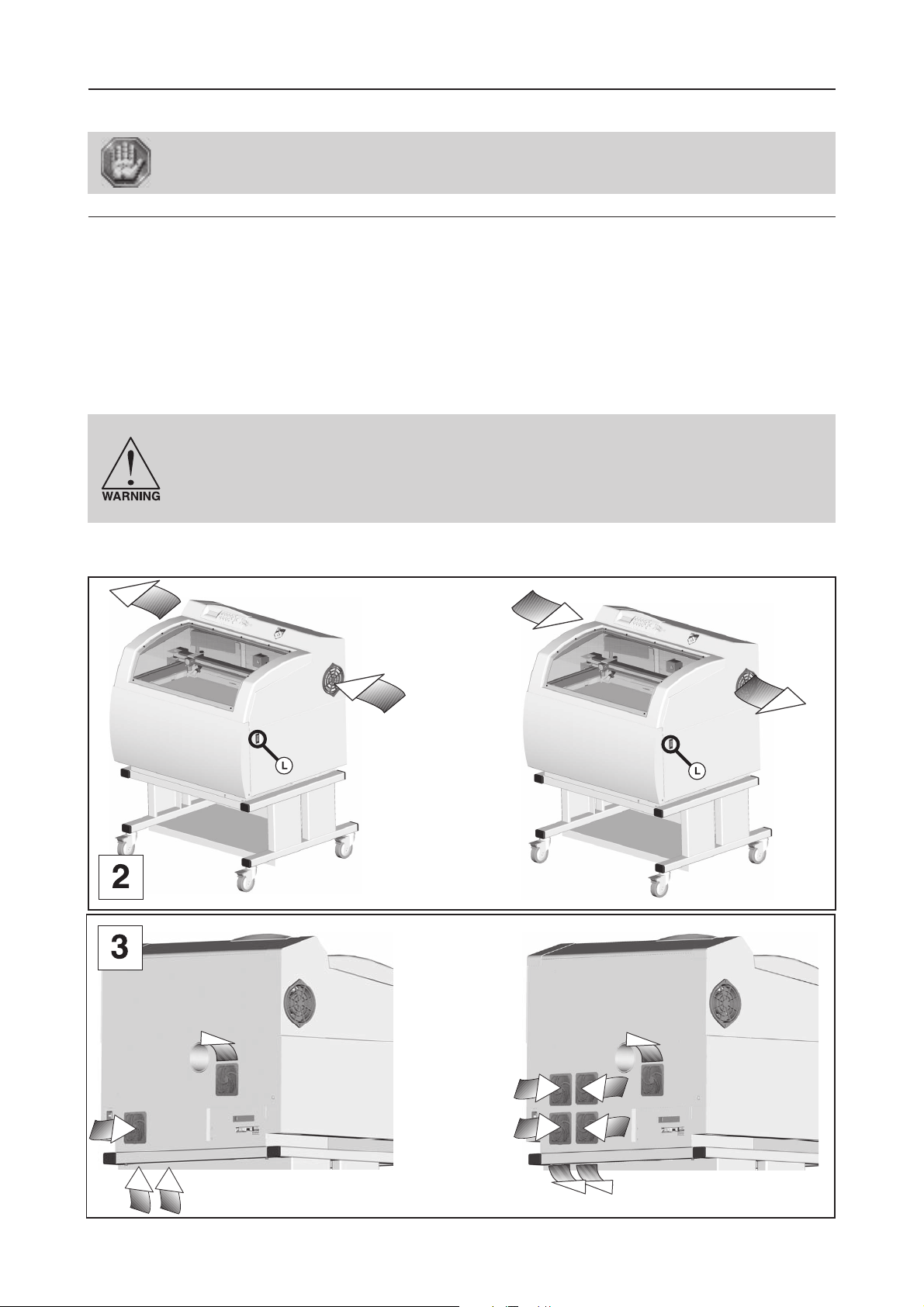
Physical installation recommendations
• Put the Gravograph machine onto a stable flat, clean surface able to carry loads:
- of least 176.4 lb (80 Kg) (L-SOLUTION 700).
- of least 331 lb (150 Kg) (L-SOLUTION 800).
- of least 375 lb (170 Kg) (L-SOLUTION 900).
• Place the Gravograph LASER engraving machine in a clean and ventilated environment such as an office environment
and make sure the machine is well-ventilated (pict. 1 and 2). Choose a place providing the shortest and most direct
path to the exhaust ductwork (not provided). Refer to exhaust requirements later on in this section.
Avoid small, enclosed, non-ventilated areas. After LASER engraving or cutting, certain materials keep on emitting fumes
for several minutes after the processing has been completed. Having these materials present in a confined, unventilated
room can contaminate the room.
To ensure a good ventilation, it is necessary to leave a 8" (=20 cm) clearance all
around the machine:
Do not confine the back of the machine by surrounding it with furniture, shelving,
backing it into a corner, etc. The rear side of the LASER system must be allowed to
"breathe". Otherwise, it can overheat the LASER tube, the power supply, and/or the
CPU module.
Overheating may cause serious and very costly damage to the LASER system.
LASER systems of this class use fans to keep the LASER tube and electronics cooled during operation. Maintain the room
temperature at the recommended ambient temperature range outlined previously in the following page.
L-SOLUTION 800
LASER 10, 25, 40W
L-SOLUTION 800
LASER 25W
L-SOLUTION 800
LASER 60, 80W
L-SOLUTION 800
LASER 10, 40, 60, 80W
First contact
L-SOLUTION 800 machine . 15
Page 16
Installation
Ambient room temperature MUST be between 50 and 95 degrees F(10 and
35 degrees C).
• If transporting the LASER system from a very cold or very hot environment to the proper operating environment, the
LASER system must be allowed time to adjust to the ambient temperature. To do this, turn on the LASER system (and
chiller if applicable), and let the system idle for 15 minutes before processing materials. This will allow the ambient
temperature to circulate through the LASER system to either warm it up or cool it off.
Ambient room dewpoint temperatures MUST be less than 50 degrees F (10 degrees C).
• Normal lighting is sufficient to use the machine (Inside the work area of the L-SOLUTION 900 machine, there is an electric
lighting device with ON/OFF switch).
• Clear the work surface so that you can
- easily and quickly access all external parts of the machine,
- quickly access, in case of necessity, the main stop button (L) on the engraving table (pict. 1),
- make sure that all moving parts of the machine have enough room to move freely,
- place the computer within 10 feet (3m) of the machine, if planning to connect the LASER engraving system
to a computer through the parallel port (the maximum recommended parallel cable length is 10 feet (3m)).
- avoid any accidental unplugging of the cables.
The connectors screws must be very tight to avoid accidental disconnection of the
cables while the machine is turned on as this could permanently damage the electronic
cards.
• If connecting an additional LASER system or other printer to the same computer, we recommend the installation of an
additional parallel port into the computer. DO NOT use a manual A/B type switch box. This creates electrical noise which
can cause an engraving problem or damage the LASER system and/or the computer’s electronics.
• Protect your Gravograph equipment against:
- Moisture (rain, snow, condensation, etc.),
- Heat (direct sunlight, heating, etc.),
- Sudden changes in temperature,
- Dust (exhaust pipe, sand-blasting or sandpapering systems),
- Liquid splashes, spillages on the electronic rack, cables and connections, and any other part of the machine; unless
recommended by GRAVOGRAPH (e.g. lubrication),
- Vibrations,
- Electric or electronic radiation.
The electrical plug acts as a sectioning device. it is therefore important that you set
up the machine in order to always have easy access to the power cable.
L-SOLUTION 800
L-SOLUTION 800 machine . 16
First contact
Page 17
Installation
Exhaust system installation recommendations
To properly exhaust fumes and smoke from the LASER engraving system during operation, you must have a proper exhaust
system.
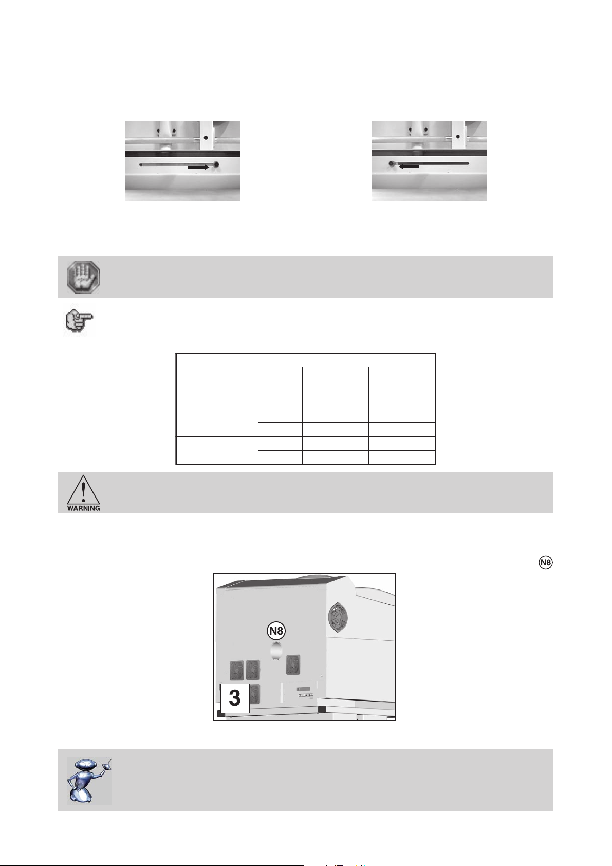
A slide gives the possibility to select two distinct air exhaust system modes :
- Head mode (Exhaust to the level of the head):
the more effective but a high-performance vacuum
exhaust system is required.
- General mode (general Exhaust ) :
gives the possibility to adapte with an air exhaust system
which have a good air draught but with a small vacuum.
An air inlet is provided in the double door.
Avoid to combine the two exhaust system modes.
For the cutting works, it is also possible to have an exhaust to the level of the table (in
general mode).
The air exhaust system MUST comply with the following minimum requirements (according to the mode):
SCITSIRETCARAHCROTCARTXEDEDNEMMOCER.NIM
edomdaeHedomlareneG
3
h/051≥003≥
m
tuphguorhtria.xaM
3
nim/72.3≥45.6≥
dray
muucav.xaM
retemaidteltuO
aPk02≥5.0≥
ISP9.2≥70.0≥
mm05001
ni"1
23/13
61/51
"3
Never operate the LASER engraving system without a properly installed and operating
exhaust system. When cut or engraved, some materials can produce fumes that are
hazardous in concentrated amounts.
To install the exhaust system properly, we recommend having the exhaust system installed by a licensed contractor
compliant with safety and local code requirements as well as being able to calculate the correct size blower required for
your particular installation.
The fume exhaust to the air exhaust system goes through the tube connected on the rear side of the LASER machine
(pict. 3).
L-SOLUTION 800
Air-assist requirements (compressor optional)
In order to use the Air-assist system (air seal), you should use an air compressor
(optional accessory, not delivered) that has the following characteristics :
- Power = 30 W
- Air draught = 0.0196 yard3/mn or 3.87 US gallon/mn
(15 l/mn)
First contact
L-SOLUTION 800 machine . 17
Page 18

Installation
Computer requirements
The following is our minimum recommended computer configuration. Using a faster computer with more capacity will
increase efficiency and throughput. Although using a computer that does not meet our minimum recommendation might
be acceptable to you, a faster computer will definitely pay for itself in a short amount of time.
- Pentium 500 MHz or equivalent
- 128 MB of RAM (256 MB recommended)
- 4 Gigabyte hard drive or bigger (10 gigabyte recommended)
- 15 inch color VGA monitor (17 inch recommended)
- 3.5" floppy disk drive
- CD-ROM Drive
- USB Port 1.1 or 2.0
- Mouse or other pointing device
- Microsoft Windows 2000® (XP, NT)
- 300 DPI Optical Resolution Scanner
Remember that the LASER system is an output device just like a printer is. The faster you can create graphics and
manipulate your software, the faster you can download to the LASER system to keep it producing.
Software suggestions
Gravograph Engraving software
- LaserStyle (Windows 2000®, XP, NT)
Font requirements
True Type
We recommend using True Type fonts only. TrueType fonts are the most versatile and should be used whenever possible.
They provide the best print quality and will print well at any size.
PostScript
We do not recommend using PostScript fonts. The LASER system is NOT a PostScript printer and therefore has no capability
of printing PostScript fonts. Sometimes a PostScript font will print if you are running Adobe Type Manager (ATM). Adobe
Type Manager converts PostScript fonts to bitmapped fonts before sending the information to our printer driver. Using ATM
does not guarantee that the PostScript font will print properly. Therefore it is NOT recommended.
Bitmap
Bitmapped fonts only print well when used at the specific point size they were designed for. This point size is usually
indicated in the font name such as Times Roman 12. If a font is only available in bitmap form, you must print it at the size
it was created for. Scaling the font larger will result in a more jagged looking character although scaling it smaller produces
good results.
Tip
If you are having any problems printing a font and you cannot figure out what is going on, select the font and «convert
to curves» or «convert to paths» in your graphics software. This will convert the font into a bitmapped image and will print
correctly to the LASER system. Refer to your graphics software on how to convert fonts.
As you can see, we strongly recommend the use of True Type fonts only.
L-SOLUTION 800 machine . 18
First contact
Page 19
Installation
Electric installation recommendations
Please refer to the label (diagram 1) « INPUT POWER » near the system’s ON/OFF switch and power inlet for your
system’s electrical requirements. Make sure that your electrical outlet is capable of providing the proper voltage, frequency
and amperage that your LASER system needs.
This material is «class 1». The mains plug MUST always be connected to a neutral
socket and comply with the regulations in force in the country of installation. If you
do not have a plug of this type, have one installed by an approved electrician. Under
no circumstances should you depart from this instruction.
In order to avoid any interference with the outside, the user is advised to follow the instructions below.
• Plug the Gravograph machine into a mains line, avoiding having several machines on the same line (several plugs on the
same line or using a multi-plug).
Exception : If other items are connected to the machine (e.g. a computer or an ISIS console linked
• Avoid using the same line to supply inductive or capacitive machines as well as the Gravograph machine (motors,
electrosluices, chargers, etc.).
• Avoid using a manual or automatic switch on the same mains line as the Gravograph machine (relay, temporizer,
programmer, automatic circuit breaker, automatic switch, etc.).
• Check that machines surrounding your Gravograph machine comply with the standards relative to radioelectric
interference (please refer to the technical leaflet shipped with each machine). If they are not compliant, place them as
far away as possible from the Gravograph machine.
• Only use Gravograph accessories (Gravograph relay box, etc ...).
to an IS table), all your machines should be connected to the same mains line.
10/20 W :
The machine must always be switched off before connecting or disconnecting a cable
or the cylinder attachment (optional accessory).
The electrical plug acts as a sectioning device. It is therefore important that you set
up the machine in order to always have easy access to the power cable.
Do not connect this equipment to an IT power supply card..
OR
25/30/40 W : 60/80 W :
First contact
L-SOLUTION 800 machine . 19
Page 20
L-SOLUTION 800
Installation
Exhaust
system
L-SOLUTION 800
L-SOLUTION 800 machine . 20
First contact
Page 21
Installation
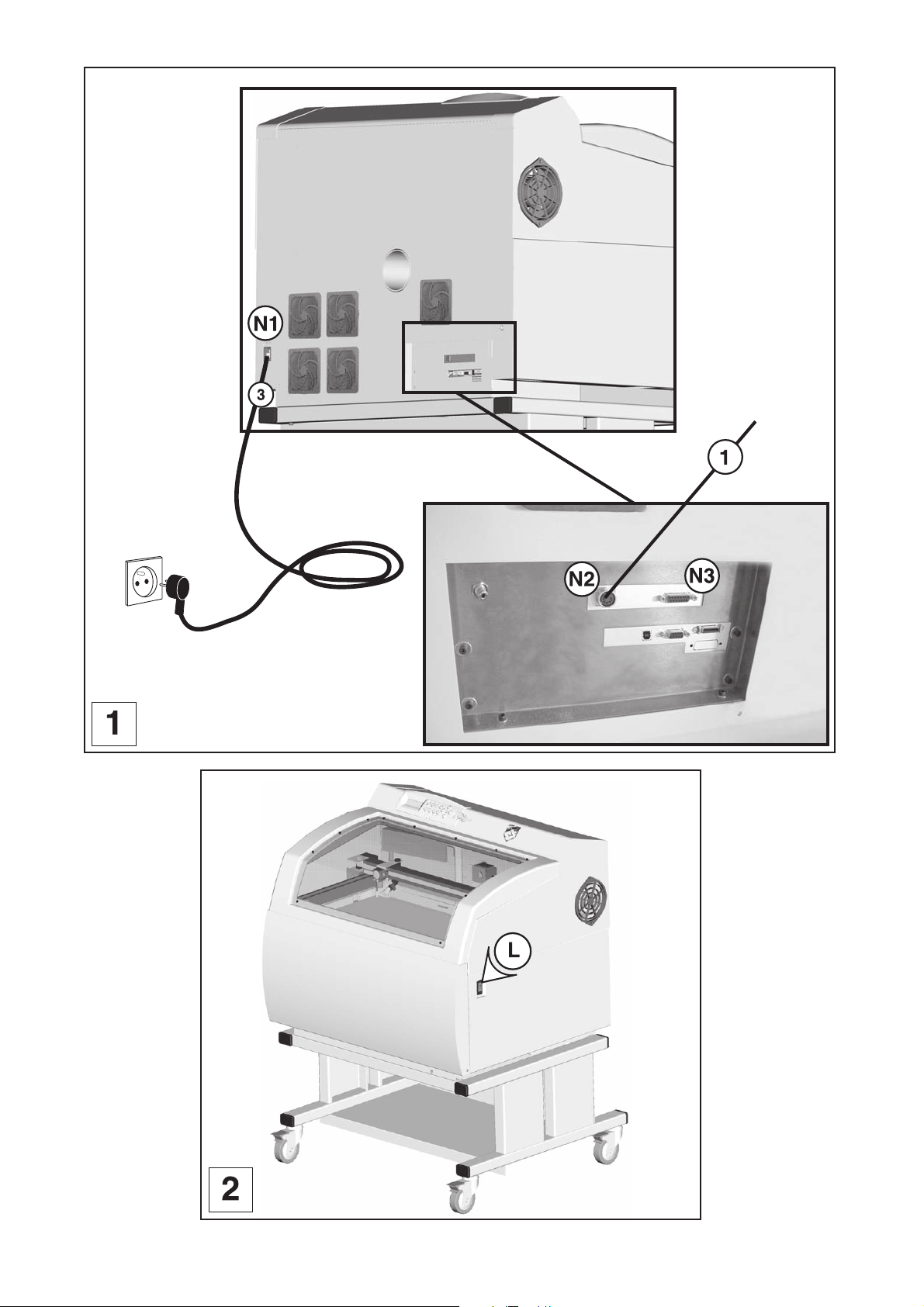
Electrical connections of the machine
Stand behind the machine (diagram 1).
1. Plug in the input/output machine-exhaust system connection cable , first to the exhaust
system, then to the LASER machine. Tighten the connectors screws using the screwdriver (3.5).
The connectors screws must be very tight to avoid accidental disconnection of the
cables while the machine is turned on as this could permanently damage the electronic
cards (label ).
Before making any user standard inputs/outputs connections you must check taht the
electric and electronic features of the different inputs and outputs are respected (see
"the Automaton function" described in the chapter "System operation" page 74).
A bad connection can irreparably damage the electronics of your machine.
2. Plug in the user standard inputs/outputs connection cable to the LASER machine if you use
the Automaton function described in the chapter "System operation" (see page 74).
The use of the function Automaton means that the engraving machine cannot be
considered individually to ensure the safety of the operator.
The engraving machine is actually integrated into a global process (the automated
production line).
Consequently, it is the final work station (engraving machine + automaton + loading
robot) that must comply with the regulations in terms of safety.
The person who fits the engraving machine within the manufacturing process is
therefore responsible for the EC compliance of the final work station.
3. Plug in the electric cable , first to the engraving table, then to the mains supply..
To cut off the mains supply to your machine in case of severe problems, unplug the
mains cable or switch off the machine with the main stop button at the front
of the LASER engraving machine (pict. 2). Make sure that you can reach them easily.
The electrical plug acts as a sectioning device. It is therefore important that you set
up the machine in order to always have easy access to the power cable.
Do not connect this equipment to an IT power supply card.
First contact
L-SOLUTION 800 machine . 21
Page 22
Powering the machine on
Switch on the machine (main stop button (L) to I position).
When switched on the ventilator of the machine will start.
The following message will be displayed on the L.C.D. screen of the machine :
SET UP
FPGA X.XX
LCD SOFT X.XX
16 Mo BOOT X.X
The machine will then issue a "beep" and a new message will be displayed :
<< GRAVOGRAPH >>
LASER VERSION X.XX
LCD SOFT X.XX
16 Mo BOOT X.X
Leave the machine plugged in even if it is not in constant use.
Problems
If one of the operational signs is missing, check the following points :
• Are both ends of the mains cable connected correctly ?
• Is the mains plug connected ? Is it live ?
If the machine does not come on, before calling a technician, please check power
connections to the mains socket.
Installation
Powering the machine off
Switch the main stop button (L) to the 0 position.
Switch the machine off in the following cases :
- if you are leaving the workstation (e.g. at the end of the day),
- physical damage (fall, fire, liquids coming into machine, etc.),
- mechanical/electrical/electronic faults, leading to a possible breakdown,
- in case of a major problem or a mechanical jamming of the machine,
- to reboot,
- for external cleaning.
Mechanical jamming
In the following cases :
- the medium to be engraved is jammed,
- an object placed in the work area is causing a jam,
Powering on again
If the machine or the programme which runs it crashes you may have to reboot the machine.
If this happens, switch the machine off. Wait 30 seconds and switch it on again.
You must wait 30 seconds. This delay helps avoid any electric shock to the machine
likely to damage the power supply.
L-SOLUTION 700 / 800 / 900 machines . 22
First contact
Page 23

Installation
Setting up transmission between the L-SOLUTION and a PC type
computer
The computer and the L-SOLUTION machine must be switched OFF.
PC computers and the WINDOWS® graphic environment being very widespread
throughout the world, we have based ourselves on these products to define the
installation and use procedures of the L-SOLUTION.
If your equipment is not compatible and you encounter problems when installing or using the product, contact your
Gravograph agent.
Connection cables
• Use Gravograph connection cables (please refer to your Gravograph vendor for a list of products available).
These cables are suited for the machines that are to be connected to.
They comply with the CEM radio waves standards and protect from external electric "attacks" (compliant with CEM
immunity and sensitivity standards).
• Do not use cables which are too long. Keep the machines as close as possible and use as short a cable as possible.
• Separate the mains cable and the transmission cable (avoid connecting the transmission and mains cables to the same
socket, etc ...).
Follow the connection procedure depending on the transmission cable supplied with the
L-SOLUTION.
The new model of machine is delivered with the following cable :
• USB cable
First contact
L-SOLUTION 700 / 800 / 900 machines . 23
Page 24
Installation
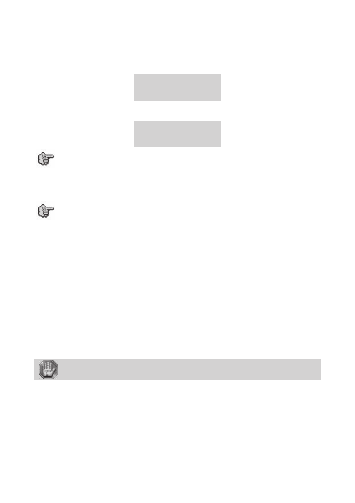
Connecting L-SOLUTION to your PC using the USB port
1. Plug the USB cable into the USB port (N5) of the L-SOLUTION 800 machine (diagram 1).
2. Plug the USB cable into the USB port of the PC.
Refer to the installation manual of the computer for the USB port (1.1 or 2.0).
L-SOLUTION 800
L-SOLUTION 700 / 800 / 900 machines . 24
First contact
Page 25
Installation
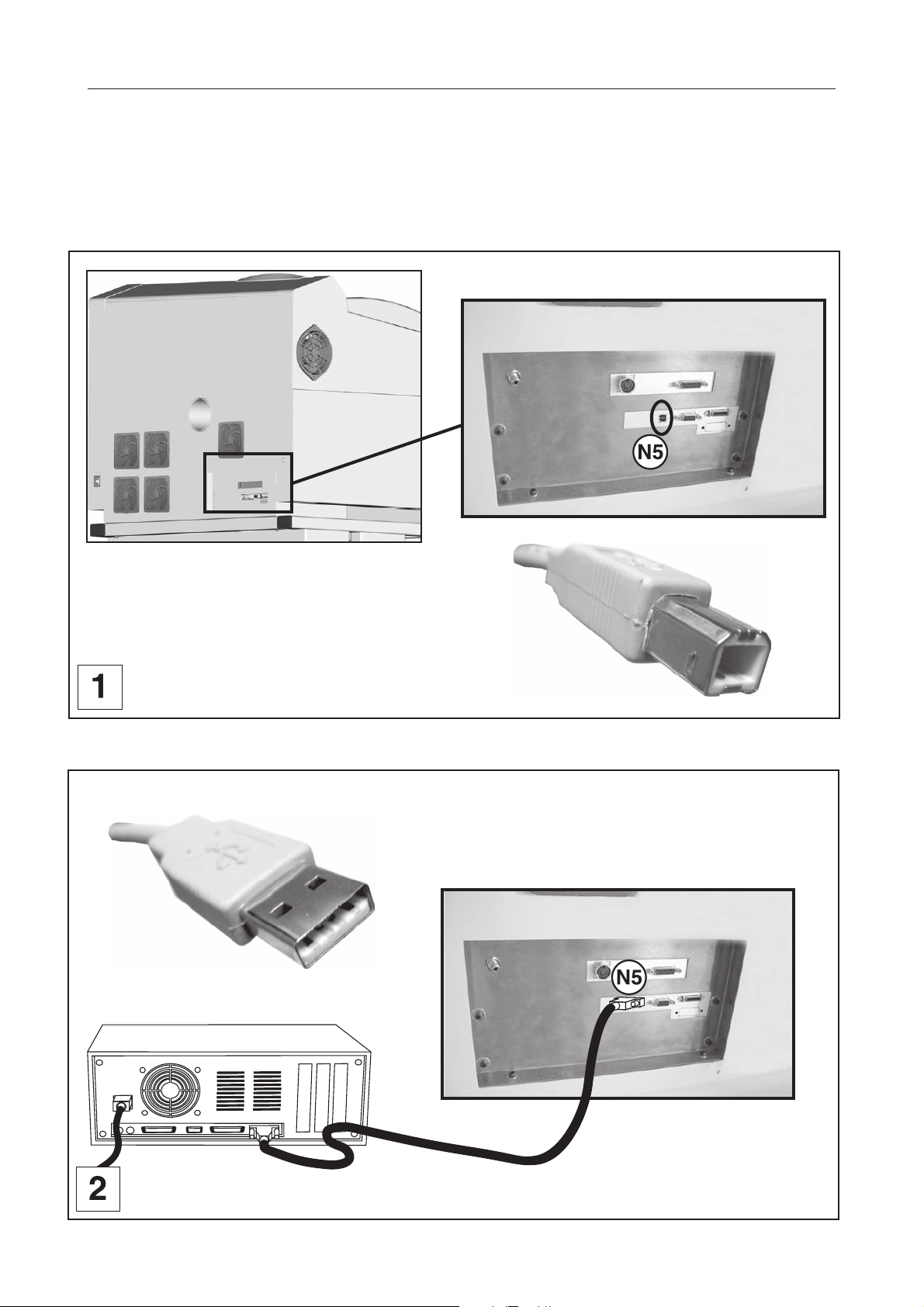
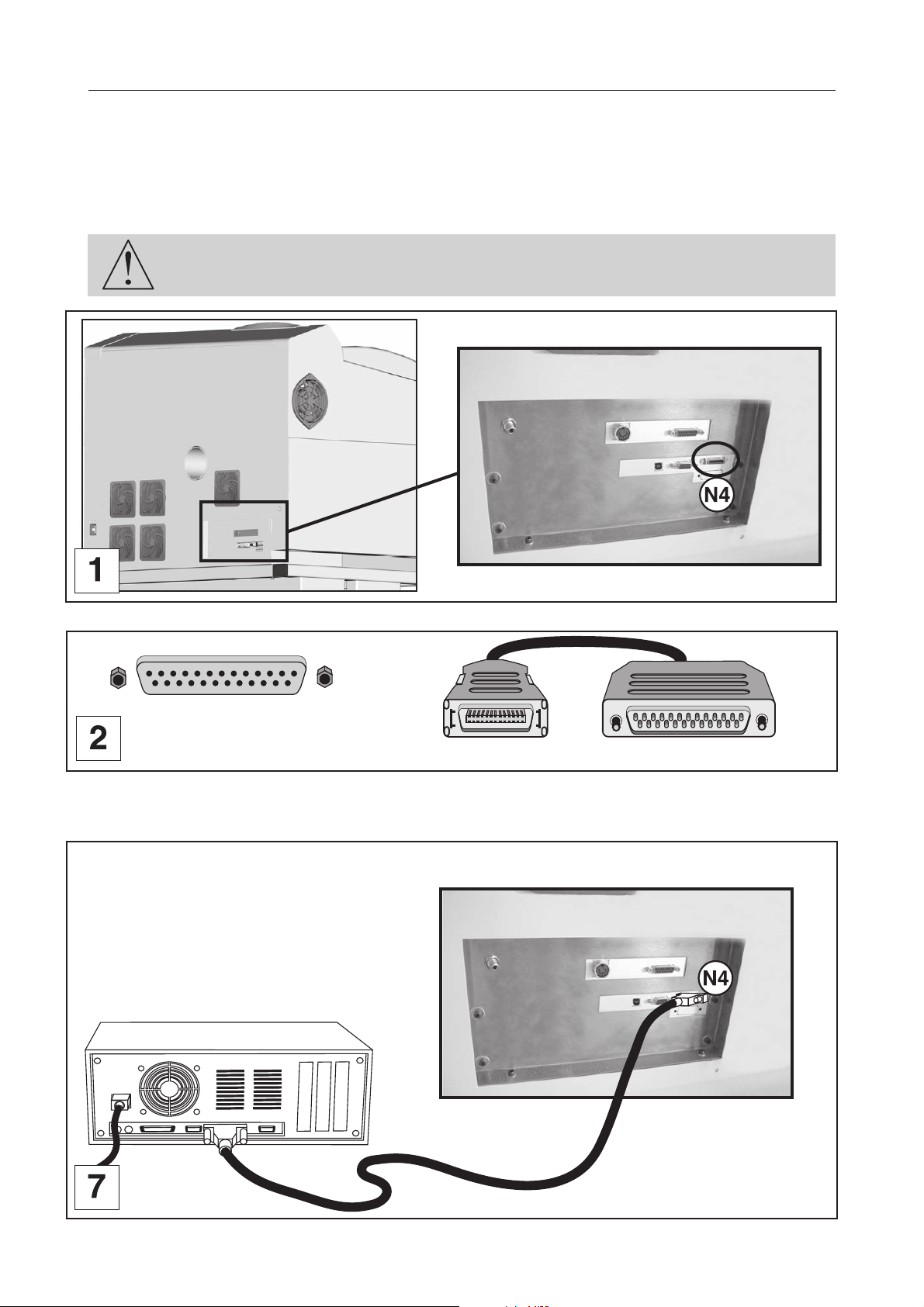
Connecting L-SOLUTION to your PC using the parallel port
1. Plug the parallel cable into the parallel port (N4) of the L-SOLUTION machine (diagram 1).
This is a 26-pin Mini-Delta Ribbon connector.
2. Plug the parallel cable into the parallel port of the PC (diagrams 2 and 7).
Refer to the installation manual of the computer for the parallel port.
The connector screws must be very tight to avoid any accidental disconnection of the
cables while the machine is turned on, as this could damage the electronic boards
permanently.
L-SOLUTION 800
1
25
L-SOLUTION
1
PC
25
First contact
L-SOLUTION 700 / 800 / 900 machines . 25
Page 26
Installation
Connecting L-SOLUTION to your PC using the serial port (only with the old machines)
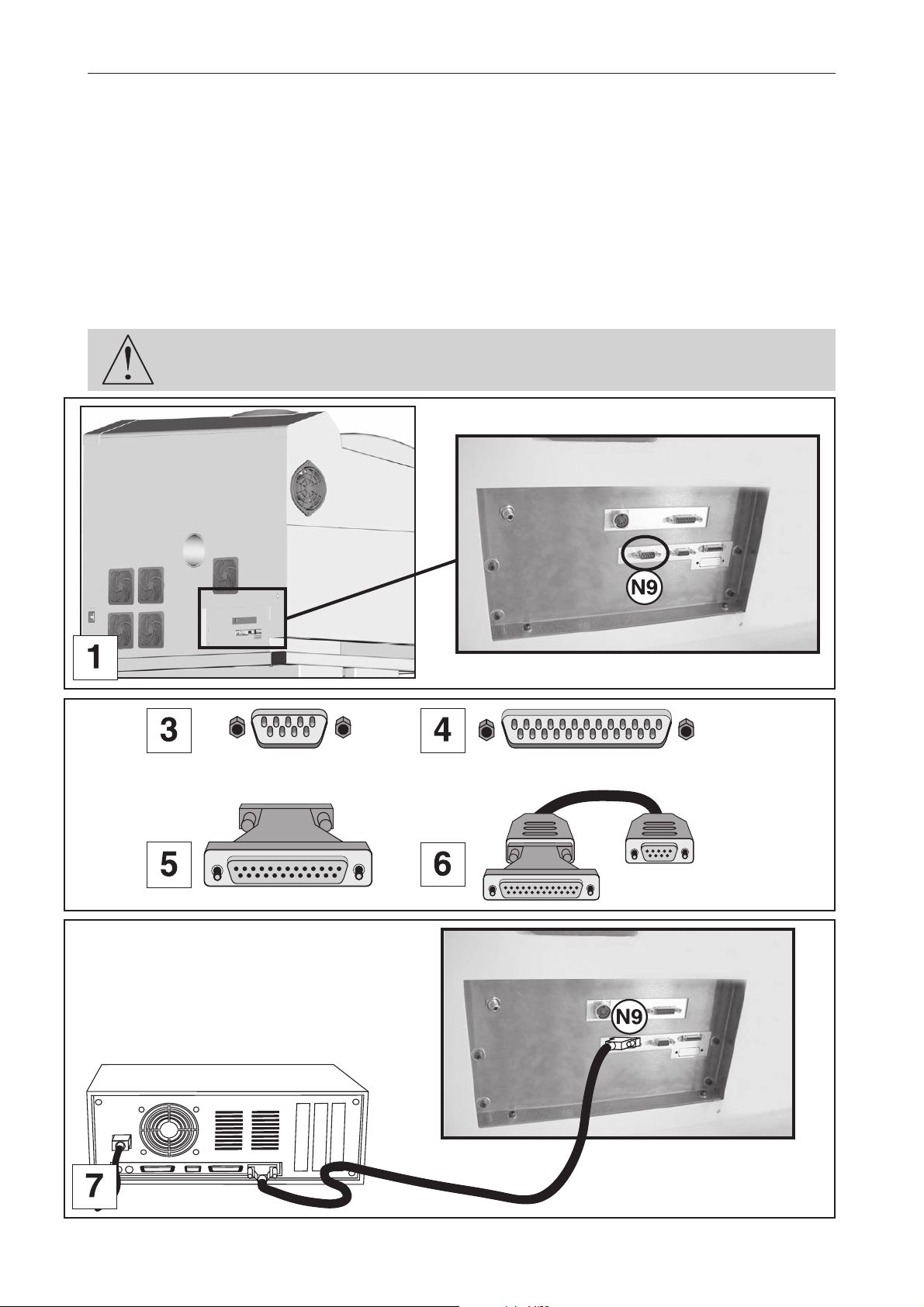
1. Plug the serial cable into the serial port (N9) of the L-SOLUTION 800 machine (diagram 1).
This is a 9-pin connector.
2. Plug the serial cable into the serial port of the PC.
Refer to the installation manual of the computer for the serial port.
PC computers can have two types of serial ports :
• 9-point serial port (diagram 3, transmission example diagram 7)
• 25-point serial port (diagram 4)
If you use a 25-point serial port, connect the 25-9 point adaptor (diagram 5) onto the serial cable
(diagram 6) before plugging it into the computer.
The connector screws must be very tight to avoid any accidental disconnection of the
cables while the machine is turned on, as this could damage the electronic boards
permanently.
Old machines
L-SOLUTION 800
1
9
1
25
1
1
9
25
1
25
1
9
Old machines
L-SOLUTION 700 / 800 / 900 machines . 26
First contact
Page 27
Machine setup (language)
1. Switch on the L-SOLUTION machine (main stop button (L) in I position).
A first message will be displayed on the screen :
SET UP
FPGA X.XX
LCD SOFT X.XX
16 Mo BOOT X.X
A new message will be displayed on the L.C.D. screen of the machine :
<< GRAVOGRAPH >>
LASER VERSION X.XX
LCD SOFT X.XX
16 Mo BOOT X.X
Wait a few seconds.
The following message is displayed on the screen :
<READY TO RECEIVE>
001 FILENAME1
PUI 40 VIT 10
DPIX 400 DPIY 400
Installation
2. Press
PARAMETERS
FILE
INFO
CONFIGURATION
3. Select the CONFIGURATION menu.
To choose the CONFIGURATION menu, press as many times as necessary
To validate your choice press
L-SOLUTION 800
LANGUAGE ENGLISH
SERIAL PORT
DISPLAY UNIT MM
4. Select the LANGUAGE menu.
To choose the LANGUAGE menu, press as many times as necessary
To validate your choice press
First contact
ENGLISH
FRENCH
DEUTSCH
L-SOLUTION 700 / 800 / 900 machines . 27
Page 28
Installation
5. Select the language you want ("ENGLISH").
When you receive your L-SOLUTION machine, it is set up to display the messages in English.
To choose the language you want, press as many times as necessary.
To validate your choice press
The following message is displayed on the L.C.D. screen :
L-SOLUTION 800
LANGUAGE ENGLISH
SERIAL PORT
DISPLAY UNIT MM
6. Select the machine menu (L-SOLUTION 800)
The programme used by the L-SOLUTION 800 machine is also used by other GRAVOGRAPH machines.
To choose the machine menu press as many times as necessary.
To validate your choice press
L-SOLUTION 700
L-SOLUTION 800
L-SOLUTION 900
L-SOLUTION 500 XL
7. Select the L-SOLUTION machine you want
To choose the machine you want, press as many times as necessary.
To validate your choice press
L-SOLUTION 800
LANGUAGE ENGLISH
SERIAL PORT
DISPLAY UNIT MM
8. Press
The following message is displayed on the L.C.D. screen :
<READY TO RECEIVE>
001 FILENAME1
PUI 40 VIT 10
DPIX 400 DPIY 400
L-SOLUTION 700 / 800 / 900 machines . 28
First contact
Page 29

Printer driver
The printer driver of the LASER machine
This section describes how the computer controls the LASER system through the printer driver.
It defines some very important terms that you need to know in order to operate the system correctly.
How the computer controls the LASER machine
The LASER system is a unique type of output device. Let’s call it a very sophisticated printer/plotter.
A regular LASER printer is a "raster"-based output device. So is a bubble jet, ink jet, or dot matrix printer.
A plotter is a «vector» based output device.
The difference lies in the way the characters and other graphics are formed. To explain what «raster» and «vector» are,
let us use the example of trying to print the letter «T» (diagram 1). A raster printer will make a back-and-forth motion
to create the character whereas a vector plotter will follow the path of the outline of the character.
The LASER system can actually raster the image, vector the image, or do both raster and vector motions. The LASER
systems printer driver works directly with your software program to send the correct image to the LASER system.
The LASER system is an output device just like a printer or plotter is.
Once the graphic is created on your computer system, you print the graphic the same way you would print to a LASER printer
or plot to a plotter. This information is then sent down to the LASER system through the parallel cable and is stored in the
LASER systems RAM memory.
Once the file is in the memory, press the «Start» button on the control panel to begin processing.
The only real difference between how a LASER printer or a plotter works compared to the LASER system is that the LASER
printer driver also has control on how much LASER power as well as motion system speed is applied.
First contact
L-SOLUTION 700 / 800 / 900 machines . 29
Page 30
Printer driver
Installing the Windows® (Windows 2000®, XP® or Windows 98®) printer driver.
The printing driver of the LASER machine is delivered on a CD-ROM. It should therefore be installed and selected in
Windows® (Windows 2000®/Windows XP®/Windows 98®).
It enables your software to transfer the information necessary for engraving to a LASER machine.
The following paragraphs describe the procedure for setting up Windows® so that the C.A.D. software can use the LASER
machine as a printer connected to the computer's serial or parallel port.
Complete understanding of how Windows® works is essential to the operation of the LASER system. Before continuing,
please refer to the Windows® owner’s manual regarding installation, use, and operation.
For a connection L-SOLUTION/PC using the USB port, plug the USB cable into the USB
port of the L-SOLUTION machine and into the USB port of your computer. Then switch
on the L-SOLUTION machine before installing the L-SOLUTION machine driver.
1. Power ON your PC.
2. Insert the CD-Rom which contains the driver of the L-SOLUTION machine (provided with the
machine)
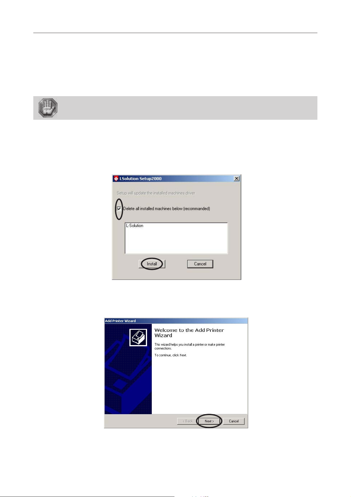
3. Wait for the opening of the "L-SOLUTION Set Up 2000":
4. Select "Delete all installed machines below (recommanded)" and click "Install".
5. When the «Add Printer Wizard» appears click «Next».
L-SOLUTION 700 / 800 / 900 machines . 30
First contact
Page 31
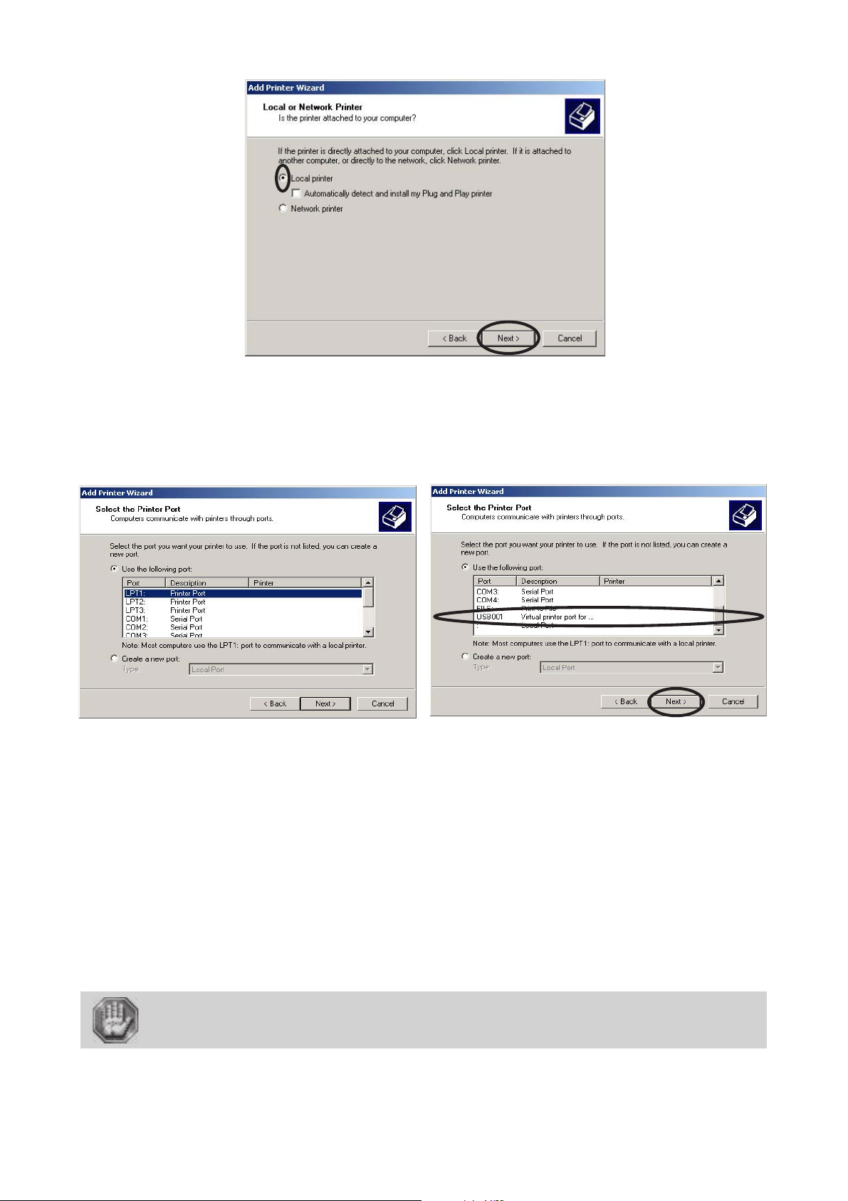
6. Click «Local Printer» and click «Next».
Printer driver
7. Click the port your LASER system is connected to and click «Next».
LPT port if you have set up the transfer with a suitable Gravograph parallel cable, connected
to the parallel port of the engraving machine and an LPT port of the computer.
COM port if you have set up the transfer with a suitable Gravograph series cable, connected to the series
port of the engraving machine and a COM port of the computer.
USB port if you have set up the transfer with a suitable Gravograph USB cable, connected to the USB port
of the engraving machine and an USB port of the computer. As soon as the machine and the PC computer
are connected and switched on, a virtual USB port is created automatically (ex: "USB001 (Virtual printer
port for USB)").
Please refer to the installation guide shipped with your computer to identify the port the
transmission cable should be connected to.
Most computers have at least one parallel port called LPT1 and 2 series ports, called COM1 and
COM2. COM1 is generally used to connect the mouse. Ports LPT1 and COM2 can be used
to connect your engraving machine.
If you select a COM port, set up the serial link or your computer ! (see the following
paragraph).
First contact
L-SOLUTION 700 / 800 / 900 machines . 31
Page 32

Printer driver
8. When the «Manufacturer» and «Printers» menu list appears click «Have Disk»
(Do not look for the printer in the menu).
9. Indicate where is the driver (on the CD-Rom already inserted). The driver for Windows 2000 and
Windows XP is in the folder "LSolution2000" and the driver for Windows 98 is in the folder
"LSolution98" :
9a. Select the drive where is the
CD-Rom which contains the driver of the machine.
L-SOLUTION 700 / 800 / 900 machines . 32
First contact
Page 33

9b. Select the folder where is the driver
for your Windows version (in
LSOLUTION98 for Windows 98 or in
LSOLUTION2000 for Windows 2000
or XP) :
9c. Click "Open".
Printer driver
9d. Click "Open".
10. Click «OK».
First contact
L-SOLUTION 700 / 800 / 900 machines . 33
Page 34

11. DO NOT click «Have Disk» again, click «Next».
Printer driver
12. Choose if you would like to set it as your default printer and click «Next».
13. Choose if you would like to share your printer with someone else and click «Next».
L-SOLUTION 700 / 800 / 900 machines . 34
First contact
Page 35

14. Select «No» when it offers to print a test page, and then click «Next».
Printer driver
15. An “Completing the Add Printer Wizard” window appears with a reminder of the information
about the parameters chosen for the printer driver. Click «Finish».
16. Click "OK" and restart your computer to activate the new driver :
17. Your driver installation is now complete. Store your driver disk in a safe place.
Now, to transfer the engraving to your L-SOLUTION machine, just like with a printer, all you need to select in the "Print..."
option.
First contact
L-SOLUTION 700 / 800 / 900 machines . 35
Page 36

Printer driver
Setting up the serial transmission
Synchronize the serial link settings between the computer and the engraving machine, each time you
- set up a printer using a COM port,
- select this printer to transfer the composition.
1. In the Windows 2000® Taskbar , click "Start".
2. Click the Settings option of the Start menu.
3. Click the Control Panel option of the Settings menu.
4. Click the System icon of the Control Panel.
L-SOLUTION 700 / 800 / 900 machines . 36
First contact
Page 37
Printer driver
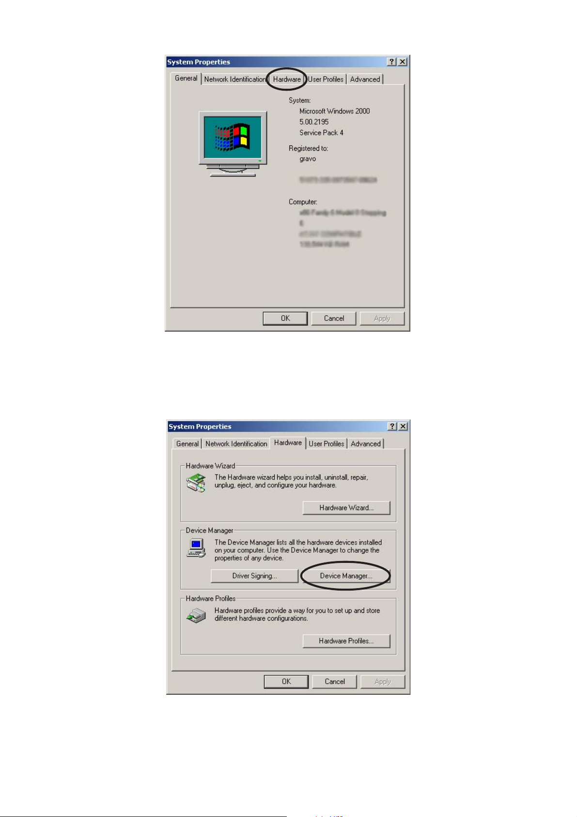
5. Click the Hardware tab, and then Device manager In the System Properties dialog.
First contact
L-SOLUTION 700 / 800 / 900 machines . 37
Page 38

Printer driver
6. Click the "+" in front of the Ports option (COM and LPT) of the Device Manager list.
7. Double-click the COM Port used by the link.
L-SOLUTION 700 / 800 / 900 machines . 38
First contact
Page 39

Printer driver
8. Click the Port settings tab of the Communication Port Properties dialog.
9. Enter the serial settings of the machine (please refer to the manufacturer's guide).
The serial link of your L-SOLUTION machine is set up as follows:
• Transfer rate : 9600 Bauds
• Number of data bits : 8
• Parity : none
• Number of stop bits : 1
• Transfer protocol : RTS/CTS (equipment)
10. Click "Advanced...".
First contact
L-SOLUTION 700 / 800 / 900 machines . 39
Page 40

Printer driver
11. In the "Advanced Settings for COM" dialog , remove the "Use FIFO buffers" function which is activated
by default.
12. Click OK to validate.
If the serial settings between the machine and the computer are different, the
composition will not be transferred in the best conditions (risk of transfer errors,
altering the final engraving result)!
Now, to transfer the engraving to your L-SOLUTION machine, just like with a printer, all you need to select in the "Print..."
option.
L-SOLUTION 700 / 800 / 900 machines . 40
First contact
Page 41

Printer driver
First contact
L-SOLUTION 700 / 800 / 900 machines . 41
Page 42

Printer driver
L-SOLUTION 700 / 800 / 900 machines . 42
First contact
Page 43

Printer driver
Driver controls
The Printer Driver for Windows 2000® (driver for short) has the appearance of other Windows 2000® printer drivers
(pict. 1). A thorough understanding of how Windows 2000® operates is essential to operating the driver’s controls. Please
refer to your Windows 2000® manual or online help screen on how to install, operate, and troubleshoot Windows 2000®.
About of tab
This «About of» tab (pict. 1) is controlled by Windows 2000® and is present in all Windows 2000® Drivers. For information
on how to use the controls located in this tab, please refer to your Windows 2000® manual or online help screens.
The “?” in the top right corner of every tab takes you to the driver's online help screens.
By clicking on the photo of the machine it is possible to (pict. 1) :
- to load a new version of the machine program
- select bridge X installed on the machine :
first bridgeX second bridge X third bridge X
- select the connections installed on your machine :
Serial RS232 / Parallel connections (Old machines)
USB / Parallel connections (New machines)
- choose a storage folder for your engraving job files (JOB):
Storage folder example ("Presets Path" ) : C:\L_SOLUTION\Job
- to send an engraving test file to adjust your LASER alignment :
1 - Adjust the power of your laser based on the material used for engraving the test file.
2 - Start the test file on the machine
13 lines (numbered from 0 to 12) of vertical lines are then engraved :
6
- to send an engraving test file to adjust your "Tickle" parameter (pict. 6):
First contact
3 - Select the number of the best engraved line (for example line no. 6 - pict. 3 and 4)
4 - Apply (pict. 5)
5 - Confirm (pict. 5)
The "Tickle" adjustment is described in the "General maintenance" chapter.
L-SOLUTION 700 / 800 / 900 machines . 43
Page 44

Printer driver
LASER Settings tab
(pict. 1)
This LASER settings tab is used to adjust the various settings required for the LASER engraving.
L-SOLUTION 700 / 800 / 900 machines . 44
First contact
Page 45
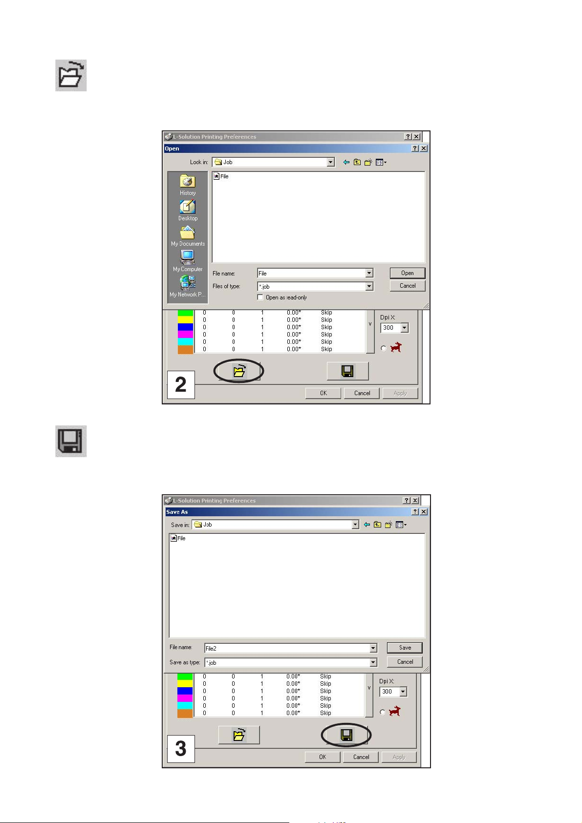
Open
(image 2)
used to open a job file corresponding to a saved engraving job.
Printer driver
Save
(image 3)
used to save an engraving job in the form of a job file.
First contact
L-SOLUTION 700 / 800 / 900 machines . 45
Page 46

Printer driver
Definition of the machine used
(pict. 1)
A list of the machines available appears by clicking the “machine” drop down menu . Select the name of the machine
you want to use.
Definition of the plate
(pict. 1)
A list of 3 available pre-defined plates is displayed by clicking the “plate” drop down menu ("Default","Default rubber
stamp", "Untitled") . Select the name of the plate you want to use.
From these 3 pre-defined plates, you can define another plate by entering its dimensions:
Values correspond to the plate dimensions you have to enter for them to be EXACTLY the same as those defined in
your software; otherwise there might no output, a partial output or a poor alignment of the graphics. The operator has to
enter the suitable setting values (the maximum dimensions allowed are those of the machine maximum engraving area).
Values correspond to the original engraving which is the default value of the machine (point (0.0) in the top left corner
of the engraving table).
Once your new parameters defined, save them with a new name of plate. Change the name and click (+) in order to add
it in the list of your plates. Click (-) in order to delete the selected plate. The 3 pre-defined plates "Default","Default rubber
stamp" and "Untitled" can not be modified or deleted.
L-SOLUTION 700 / 800 / 900 machines . 46
First contact
Page 47

Printer driver
Selecting the power available on the LASER machine
(pict. 2)
By clicking on the "power"" , pull-down menu the list of available powers is displayed. Select the power for your machine.
Plate orientation
(pict. 3)
Determines the orientation of the graphic and of the text to be engraved on the plate.
First contact
L-SOLUTION 700 / 800 / 900 machines . 47
Page 48

Printer driver
L-SOLUTION 700 / 800 / 900 machines . 48
First contact
Page 49

Printer driver
Graphics
The LASER machine acts like a black and white printer (black is engraved and white is not), so the photographs (bitmaps)
in a scale of grey or colours as well as multicoloured clipart images are transformed into smooth images. This is done when
the LASER machine reproduces the image. This process is very similar to the way magazine photos are printed, as well as
photos obtained from LASER printers
A conversion must be made by your software or by the printing drive of your LASER machine. The following paragraphs
describe the various conversion possibilities with the printing drive of the LASER machine in the normal mode (image 1)
and rubber mode (image 2)
« Automatic » (only normal mode - image 1)
is used to run the printing to convert the colours in the cliparts and texts (everything that is generated starting from graphic
forms and texts) to levels of grey so that it can automatically assign the adequate power to each pixel based on the level
of grey and proportional to the power assigned to the colour black.
The colours in the photos (bitmap format) are processed in the same way.
Engraving of the entire job is done in one scan. The engraving parameters (max power, speed etc.) are set by the colour
black.
« Filling » (normal and rubber mode - images 1 and 2)
is used to process the colours in the same way as the automatic mode with a power range divided into 64 levels. For each
of these levels a specific filling is applied.
The engraving parameters (max power, speed etc.) are set by the colour black.
All the points are engraved with the same power (set by the colour black).
Engraving of the entire job is done in one scan.
« Black and white mode » (only rubber mode - image 2)
is used to process the colours in the same way as the automatic mode for the cliparts and texts (everything generated
starting from the graphic forms and texts) and sets the limit of the image to 50% of black (power set by the user) for the
photos. Each pixel over 50% of black is converted to white (engraved) and each pixel less than or equal to 50% of black
is converted into black (not engraved). This operation is similar to a photo duplication process with a photocopier.
« User colours » (only normal mode - image 1)
is used to run the printing to convert the colours in cliparts and texts (everything generated starting from graphic
forms and texts) from 8 basic colours set in the print drive interface. The other colours are converted to the closest
colour of these 8.
Engraving of each colour block is done separately with its associated engraving parameters.
The colours in the photos (bitmap format) are processed like in automatic mode. Engraving of the photo block is
effected after the last colour block with engraving parameters of the colour black.
« Negative image » (normal and rubber mode - images 1 and 2)
used to run printing to convert an image into its negative image. All the objects which were filled with black and thus
engraved become images filled with white and no longer engraved.
« Photo mode » (normal and rubber mode - images 1 and 2)
"Photo mode" scatters the pixels in a random pattern to represent shading. Each obtained dot will be engraved with the
same power (the power of the black color). The optical illusion of shades of grays appears due to the density of these dots.
Therefore the result will be the same whatever the material you use.
First contact
L-SOLUTION 700 / 800 / 900 machines . 49
Page 50

Printer driver
L-SOLUTION 700 / 800 / 900 machines . 50
First contact
Page 51

Printer driver
Settings
(pict. 1 and 2)
Color
The colors in the driver allow you to assign different LASER settings and modes to your multi-colored drawn artwork. This
enables you to control the depth of the burn as well as different visual effects to your material. You can assign settings
for up to eight (8) DRAWN colors.
Power Setting
LASER power is controlled by assigning the percentage of power from 0 - 100% to each color used in the graphic drawing.
Since the LASER is pulsed proportionally, this percentage represents how long the LASER remains on for each LASER pulse
fired.
Basically, the power setting is directly related to how deep the engraving will be.
The Power setting is linear meaning that 100% power will engrave or cut twice as deep as 50% power.
Speed Setting
This setting controls how fast the motion system moves in a percentage of the maximum speed of the LASER engraver.
The actual time that an object takes to engrave or cut is entirely dependent on the size of the graphic. Power and speed
work together in determining how deep the engraving will be. Higher power settings and slower speeds will produce deeper
engraving or cutting. You might notice that on small objects, engraving or cutting at a faster speed as opposed to a slower
speed might not produce a faster engraving time. The time it takes to engrave or cut can be related to the size of the graphic
and the mechanical ability of the engraver to achieve the speed that you have selected. If the LASER system determines
that it cannot achieve the speed that you have selected, for a graphic of that size, it will automatically adjust its speed
internally, to the maximum speed it can achieve. This is evident visually when cutting curves or circles as opposed to straight
lines, and you see the motion system slow down automatically.
Proportional pulsing of the LASER will ensure that there is no difference in the depth of cut from straight lines to curves.
Refocussing
A refocussing can be defined by the user (depth) at each pass.
The value indicated is the distance to be sent between two passes for making the engraving material rise or cutting it so
as to be within the LASER focus during the next pass (negative values are possible).
A refocussing of 0.10 mm will be carried out after each pass (0,10*).
A refocussing of 0.10 mm will be carried out before the first pass and then after each pass (*0,10).
Passes
The number of passes can vary from 1 to 9.
First contact
L-SOLUTION 700 / 800 / 900 machines . 51
Page 52

Printer driver
Rast/Vect (raster/vector)
(pict. 1)
The LASER machine can actually raster the image, vector the image, or do both raster and vector motions
(see page 29).
RAST :
All the lines of that colour set by scanning are processed and engraved. The vectorial lines are ignored.
VECT :
All the vectorial lines of that colour are processed and engraved. The lines set by scanning are ignored.
DOT : (pre-cut)
All the vectorial lines of that colour are processed and engraved as points. The lines set by scanning are ignored.
RAST/VECT :
All the lines set by scanning and all the vectorial lines of that colour are processed and engraved.
RAST/DOT :
All the lines set by scanning of that colour are processed and engraved. The vectorial lines of that colour are processed and
engraved as points.
L-SOLUTION 700 / 800 / 900 machines . 52
First contact
Page 53

Printer driver
Air assist
(pict. 2 and 3)
Air flow is in the same direction as engraving. It is used to clean and extinguish flames that may be produced
on some materials.
To activate this function you must first make sure that the air assistant is connected to a compressor (optional) (see "Air
assistant requirements" in the "Installation" chapter).
To adjust the air flow use the button on the right of the control panel (see "Front view of the machine" in the "Description"
chapter).
It needs to be set for each colour. Once activated, an asterisk appears on the line of the specific colour (pict. 3).
First contact
L-SOLUTION 700 / 800 / 900 machines . 53
Page 54

Printer driver
L-SOLUTION 700 / 800 / 900 machines . 54
First contact
Page 55

Printer driver
Resolution
This setting is the image resolution of the engraving in DPI (dots per inch = pulses per inch). There are 11 DPI settings
to choose from 50, 75, 100, 200, 300, 400, 500, 600, 800, 1000 and 1200.
The resolution can also be referred to as the vertical lines per inch or fill spacing. This is how many raster strokes per vertical
inch of travel the motion system steps down to produce the engraving.
Higher resolutions will produce cleaner and deeper engraving but take longer. Lower resolutions produce a coarser and
shallower image but are quicker to engrave.
Try the various settings and note the results.
The Y resolution automatically sets that in X
First start by setting the Y resolution and then in X as need be (as the latter’s value will be that defined in Y).
When the "Rapid" option is activated, the file transfer speed is greater, despite the request for high resolutions. This option
reduces the engraving time but causes a small loss of quality.
First contact
L-SOLUTION 700 / 800 / 900 machines . 55
Page 56

Printer driver
L-SOLUTION 700 / 800 / 900 machines . 56
First contact
Page 57

Printer driver
Rubber
(pict. 1)
The Rubber function allows one to easily make marks for rubber stamps.
Tick the Rubber box (as shown on the pict. 1) to activate this function.
Click to enter those needed by this function (pict. 2).
Button allows one to define the orientation of the engraving text or graphic. The most frequently ced orientation for
rubber stamps is the back side (as shown on the pict. 2).
The graphic representation which appears in the "Settings" window corresponds to the shoulder shape of the letter which
will be engraved :
"C" letter
Shoulder
B= 1 mm
C= 50%
D= 0.5 mm
0 %
50 %
100 %
1
0,5
0
1mm
The value corresponds to the shoulder length in mm.
The shoulder inflexion point is defined by the values and :
The value corresponds to the power requested by the user in % of the available power (defined for the black colour).
This value positions the inflexion point to a certain engraving depth .
The value corresponds to a length in mm. This value positions the inflexion point on the shoulder length.
First contact
L-SOLUTION 700 / 800 / 900 machines . 57
Page 58

Printer driver
L-SOLUTION 700 / 800 / 900 machines . 58
First contact
Page 59

Printer driver
Rubber (cont'd)
Move the cursors with the mouse to modify the values and and to create a new shoulder shape :
(pict. 1 and 2)
Shoulder
"C" letter
B= 1 mm
C= 65%
D= 0.19 mm
0 %
65 %
100 %
1
0,19
0
1mm
Modify the shoulder length to create a new shoulder shape which appears in the "Parameters" window when you click
"Apply" ("Appliquer") :
(pict. 3 and 4)
Shoulder
B= 5 mm
C= 65%
D= 0.19 mm
"C" letter
0 %
65 %
100 %
5
5 mm
0,19
0
First contact
L-SOLUTION 700 / 800 / 900 machines . 59
Page 60
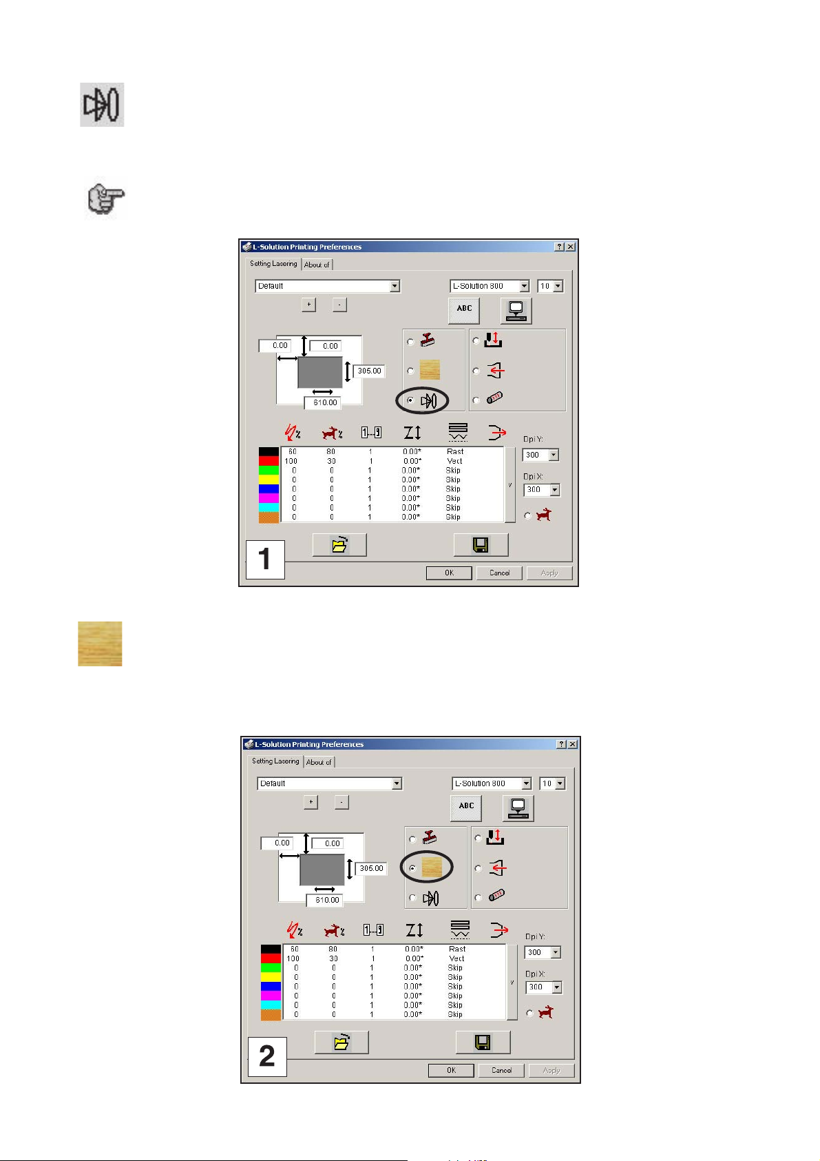
Autofocus
(pict. 1)
Once selected, autofocus is effected automatically each time engraving is started.
Deactivate the Autofocus function when you want to engrave a large set of plates of
the same thickness. This will allow you to save time in measuring or you will only do
an autofocus for the first of these plates.
Printer driver
Wood
(pict. 2)
Select this Wood function when you want to engrave a piece of hardwood.
L-SOLUTION 700 / 800 / 900 machines . 60
First contact
Page 61

Printer driver
Exhaust system
(pict. 3)
Must always be selected for gases to be discharged.
A time delay can be defined by the user (pict. 4). It corresponds to the time (in seconds) needed for stopping the filtering
once the engraving is stopped.
First contact
L-SOLUTION 700 / 800 / 900 machines . 61
Page 62

Printer driver
Cylinder attachment (optional accessory)
(pict. 1)
This selection must be used only if the optional cylinder attachment has been purchased.
Refer to the instructions provided with this option. Do not attempt to use this until you have read the rest of this manual.
There is important information about the operation of the LASER system that must be read and understood before operating
the cylinder attachment.
The user must indicate the diameter of the engraving cylindrical part (pict. 2).
L-SOLUTION 800 and 900 : max. ø = 7"
L-SOLUTION 700 : max. ø = 5"
7/8
= 200 mm
1/2
= 140 mm
L-SOLUTION 700 / 800 / 900 machines . 62
First contact
Page 63

Printer driver
Engraved objects
(pict. 3 and 4)
Once activated this function is used for the LASER head to avoid for example the edges of an engraved object.
During movements without engraving of the head, the machine table lowers to the value indicated in
When it is time to engrave it raises to the initial level set by autofocus.
.
First contact
L-SOLUTION 700 / 800 / 900 machines . 63
Page 64

Graphics software
Graphics software
Choosing the right graphics software program to run the LASER system is essential for maximum usage and control of the
LASER system.
Setting up you software correctly is essential to running the LASER system properly.
Software setup
There are many software programs that you can purchase off-the-shelf that will work with the LASER system. Some of them
can access more features of the LASER system than others. Whichever program you choose, it must be set up to work with
the LASER system. Otherwise, unexpected results may occur.
Use the following guidelines when configuring your software program.
Power Control Through Color Selection
The LASER system allows the use of 8 different colors to access 8 different power settings when cutting and engraving. This
feature is controlled by the driver. When using this power change feature with driver, the colors that are used MUST exactly
match the colors listed in the driver.
The colors are black, red, green, yellow, blue, magenta, cyan, and orange.
Some programs will provide these basic colors pre-defined and other programs may require the creation of each of the colors
by defining them in CMYK percentages.
If using a color other than the exact colors listed above, the driver will attempt to match it to a color in the driver that it
most closely resembles. The driver will then use that color’s power setting and apply a halftone pattern to represent the
original color’s shade. For example, if using a color like pink to fill a rectangle, the driver takes a reading of the percentage
of different colors used to create that color and will use the power setting assigned to one of the eight colors of the driver
that it most closely resembles.
It might be expected that the driver will use the power setting assigned to the color red but instead the driver may choose
the magenta setting and halftone the rectangle as a representation of the pink color’s lighter shade. To prevent the incorrect
assignment of LASER power, be sure to use the right colors.
Outlines and Fills
The driver distinguishes between raster mode (engraving) and vector mode (cutting) by the type of graphic artwork being
used. Basically, all graphics other than outlines of very thin line widths will be interpreted as engraved images and the raster
mode will be used for output.
If LASER cutting is desired, set the line thickness of the lines that are drawn in the graphics software to .001 inches (.1 mm)
or the smallest possible line thickness that is available.
The printer driver will interpret these objects as vectors and will cut them out providing that your software has the capability
of vector output.
Basically, all software programs have the ability to provide raster output. However, not all programs have the ability to
provide vector output even if you set the line width to the smallest thickness possible.
The use of color fills or bitmaps will cause the LASER system to engrave. The combination of engraving and cutting is
available in most graphics software. We suggest that when combining engraving and cutting objects, use different colors
for the fills and outlines since engraving requires different power settings than cutting objects. One thing to keep in mind
when creating cutting objects is that if the outline thickness is set too thick, the driver might interpret the outline as a filled
object and will engrave the outline instead of cutting. This might be desirable if engraving thick outlines is necessary. The
outline thickness at which the driver will interpret cut lines as filled objects is dependent on the software used. Usually,
any line thickness .008 inches (.2 mm) or greater will engrave. The only way to determine the cross over point for line
thickness is to experiment with different line widths. Software programs that do not have outline capabilities definitely will
not have the ability to cut.
Image Processing Order
When cutting or engraving a graphic image, the LASER system will perform all engraving first, then proceed to cutting.
Engraving will proceed in the exact order of the colors listed in the driver. For example, all black filled objects will engrave
first, then all red filled objects, then all green filled objects and so on. When all engraved objects have been completed,
the LASER system will proceed to cut any outlines present in the artwork. Unlike engraving, cutting will proceed in the order
from which the outlines are drawn regardless of color. There are several different ways to control the order in which the
outlines are cut. One way is to draw them in the exact order in which they need to be cut, but this is not always practical.
Overlapping Outlines
The driver does not filter outlines that overlap each other. If placing one outline one on top of another, both outlines will
be cut by the LASER system. This is a useful feature that will allow deeper cutting by passing the LASER over a single outline
path twice or more. To take advantage of this feature, duplicate the outline on top of itself.
Hidden Vector Lines in Artwork
The driver does not automatically filter out outlines that are overlapped by engraved objects such as fills. If there are filled
objects with some hidden outlines underneath, the LASER system will then engrave out the fill and cut the hidden outline
on top of the fill.
L-SOLUTION 700 / 800 / 900 machines . 64
First contact
Page 65

Graphics software
Speed optimization
It is advantageous to engrave an object in its longest direction because total engraving time will be reduced when the motion
system has to make fewer stops and starts.
If the engraving object is longer than it is tall, a greater engraving speed can be achieved by rotating the graphic 90 degrees
and placing the material in the LASER system sideways. Be aware that some graphics programs do not support the rotation
of bitmaps. In this case, it may be necessary to use bitmap image processing software to first rotate the bitmap before
importing the bitmap into the graphics program.
If the artwork contains engraved objects of the same color with a great deal of space between them in the engraving
direction, processing time can be longer since the LASER must make long strokes to engrave both objects at the same time.
To reduce engraving time in cases like these, use different colors for each of the objects but assign the same power setting
to both colors.
This will cause the LASER to engrave one object at a time, skipping over all blank space, which in many cases will reduce
engraving time. On the other hand, if the objects are relatively close together in the engraving direction, then leave them
the same color because it will be quicker to engrave them both at the same time.
Experiment with these techniques to optimize the engraving speed.
Bitmapped / scanned images
There are primarily three types of bitmaps available. They are monochrome (black and white), grayscale, and color.
Bitmaps are patterns of dots (pixels) blended to form pictures. Scanning artwork into a computer through a scanner creates
most bitmaps. Others are created by drawing them in a bitmap image processing program. The LASER system can print
all three types of bitmaps providing that either the driver or the bitmap image processing program converts the grayscale
and/or color bitmaps into a monochrome bitmap. Essentially, the LASER system is a monochromatic printer, either it fires
the beam to burn a dot or it does not fire the beam to leave an empty dot on the material.
There are several different bitmap storage formats available: TIF, BMP, PCX, and others. We prefer to use the TIFF format
because it is most widely used format. The format makes no difference to the LASER system. The difference in formats
involves how they are stored on your computer’s hard disk. Bitmaps cannot be edited in most graphics software. Some
basic functions such as cropping, scaling, or mirroring might be possible but it is usually necessary to use a bitmap image
processing software to perform a dot by dot editing, rotation, or scaling of the bitmap.
Monochrome Bitmaps
If you scan the image in monochrome (black and white) mode, set your scanner to at least 600 DPI. The higher the DPI,
the smoother the image will be. Scanning monochrome images at 300 DPI is the minimum recommended resolution but
scanning them at 600 DPI will provide a significant improvement in the image quality.
Clean it up in your bitmap image processing program and save it to your hard disk.
You can now either print the image directly from your bitmap image processing program, or import the bitmap into a graphics
program and print it from there. Monochrome bitmaps are engraved in the same manner as black filled text. The black
area will turn the LASER on and the white area turns the LASER off.
Grayscale Bitmaps
When scanning image in the grayscale mode, you should scan the image at no more than 300 DPI. Scanning at a higher
DPI does not improve image quality but it consumes more memory and will take longer to print. Grayscale images cannot
be printed directly to the LASER system. Since the LASER system actually works like a black and white printer, grayscale
images must be converted into a black and white images. To do this, either the driver will do it automatically or you can
convert the grayscale image to a black and white image in your bitmap image processing program.
Image conversion techniques into shades of grey are selected in the drive under Graphic. Please refer to the section of the
printing drive for more information on how to set this parameter.
Since the driver has a fixed method of conversion, you may want to experiment by using your bitmap image processing
program to make the conversion. These software programs usually have more options for controlling the size, angle, shape,
and the amount of black and white dots (pixels) created when converting the image. Experiment with all of the controls
to see which looks the best. Big dots look good on some materials and small dots look better on others.
Once the image is converted by your program, save it and either print it directly from that program or import it into your
graphics program and print it from there.
If you decide not convert the grayscale image to a monochrome image in your bitmap image editing program, then the
driver will do it automatically and will use settings based on the Resolution settings in the driver. Again, refer to the driver
controls section on more details about how to use the driver.
Color Bitmaps
The driver handles color bitmaps the same as grayscale bitmaps. Since color bitmaps use more memory, they are
unnecessary and are therefore NOT recommended. You can scan color photographs by using the grayscale mode or if it
is already color, convert it to a monochrome bitmap in your bitmap image processing program.
First contact
L-SOLUTION 700 / 800 / 900 machines . 65
Page 66

System operation
System operation
In this section you will learn how the LASER system actually works and will become familiar with LASER system terminology.
We will then start working with the control panel and learn how to get around in the menu system.
How it works
There are six basic components (diagram 1) that make up the LASER system, the DC power supply, the UC board, the
PUI board, the control panel, the LASER tube assembly, and the motion system.
DC Power Supply
The DC power supply converts the incoming AC electricity to 48 volts DC. This is used to power both the LASER tube
assembly and the UC and PUI boards.
UC board
The UC board is the «brains» of the system. The UC board receives informations from the computer and the control panel.
The incoming files, from the computer, are stored and treated by the UC board.
It outputs precisely timed signals to the PUI board.
PUI board
The PUI board receives information from the UC board. This information is necessary to the PUI board to output precisely
timed signals to fire the LASER beam and to move the motion system simultaneously.
Control Panel
This is where the operator controls the LASER system. It is composed of touch buttons and a LCD display. From this panel,
the operator can position the motion system, move around through the menu system in the LCD display, and run the LASER
system.
L-SOLUTION 700 / 800 / 900 machines . 66
POWER
PUI
BOARD
UC
BOARD
First contact
Page 67

System operation
LASER Tube Assembly
(diagram 2)
The LASER tube assembly is a very sophisticated device. It is composed of a plasma tube filled with a special mixture of
CO2 and other gases, and RF (radio frequency) electronics. The function of the entire assembly is to turn electrical energy
into concentrated light energy. The word LASER is an acronym for Light Amplified Stimulated Emission of Radiation.
The LASER tube assembly receives power from the 48VDC power supply and its «trigger signal» from the CPU. When the
LASER system is powered on and the trigger signal comes from the CPU, the RF electronics produce a high frequency AC
signal across the electrodes located inside the plasma tube. This causes spontaneous photon emissions from the gas
mixture that produces an invisible, infrared light beam at a frequency of 10.6 microns (µm) (0.417 10-6 inch).
The LASER beam exits the LASER tube through its output optics, bounces off the beam expander, passes through the beam
window, bounces off the #1 and #2 mirror, and finally passes through the focus lens. The #1 and #2 mirror and the focusing
lens are all mounted to the motion system. The width of the LASER beam as it exits the tube, called the «Beam Diameter»,
is about 0.14 inch (3.5 mm). The focus lens focuses the beam into a very small spot whose «Spot Size» is dependent on
the «Focal Length» of the lens.
The «Focal Length» is the distance from about the center of the lens to the point where it converges the beam into the
smallest spot possible. Using a standard 2 inches (50 mm) focal length lens, the spot size produced is approximately .005
inch (0.125 mm).
The «Focal Range» of the lens, where the beam is considered to be «in focus», is equivalent to +/- 5% above and below
the focus point.
Shorter lenses produce a smaller spot size but also have a very narrow focal range. This means that they only would be
useful for engraving very flat objects. The longer lenses have a much wider range of focus but also produce a larger spot
size that would prohibit the engraving of fine detail. This can be related to trying to write small text with a wide, felt tip
marker. There are pros and cons to the different lenses that are available for different applications. Please refer to the
"Technical characteristics" section on available lenses and their operating characteristics.
«Wattage» signifies the amount of heat energy that the LASER light is producing over a period of time. LASER energy is
measured with a LASER power meter. Do not confuse the electrical wattage rating of a light bulb or a hair dryer with the
wattage rating of the LASER system. They are two different types of measurements.
First contact
L-SOLUTION 700 / 800 / 900 machines . 67
Page 68

System operation
Indicator
Joystick
lights
Validation
Air assist
File selection
START
ENGRAVING START
PAUSE
VALIDATION
CANCEL
AIR
ASSIST
Cancel
Autofocus
Positioning red diode
Start engraving.
Stop temporarily engraving.
Access differents menus, menu exit, move to the next screen or to the next
menus (for sequential menus), settings recorded.
Access menu exit without saving last setting, return to reception when pause
(during engraving), end of reception, end of engraving.
Activate the air assist when engraving.
Start
Engraving start
Pause
Focus adjustment
FILE
SELECTION
POSITIONING
RED DIODE
AUTOFOCUS
FOCUS
ADJUSTMENT
JOYSTICK
MAIN STOP
BUTTON
L-SOLUTION 700 / 800 / 900 machines . 68
Display the following file stocked in the mac hine memory. This becomes
the current file.
Activate a LASER beam (red diode LASER) which permits to see the
head position on the plate.
Allow to carry out an Autofocus (automatic ZRef.) at any time.
Adjust manual focus (manual Z Ref.).
XY, Z head travel, selecting or adjusting a setting.
To cut off the mains supply to the machine in case of severe problems,
switch off the machine with the main stop button.
First contact
Page 69

System operation
Motion System
The motion system consists of the mechanically moving parts of the LASER system. It is made up of rails, motors, bearings,
belts, mirrors, a lens, and other parts. There are two directions of motion, left to right is called the «X» direction and front
to back is called the «Y» direction.
The PUI and the UC boards control the movement of the motors, which moves the mirrors and focus lens across the
engraving area and over the material. At the same time, it is synchronizing the LASER pulses with the position of the focus
lens.
It is this precise positioning and timing of the LASER pulses that produces the highest quality and fastest speed of engraving
To sum up, the six components work together to take the graphic image that is downloaded to the LASER system from your
computer and burn it into the material located on the engraving table inside of the LASER system.
The control panel
(diagram 1)
The control panel on the LASER system provides easy access to all of the controls necessary for cutting and engraving
operations. The control panel consists of a liquid crystal display (LCD), indicator lights, and selection buttons. The following
section will describe, in detail, how to maneuver through the menu system and the meaning of each item in the control
panel (chart 2).
The Liquid Crystal Display (LCD)
The LCD is a four line display that displays the menus that control the LASER system. It is a backlit type of display that
enhances visibility even under low light environments.
When the LASER system is powered on, the LASER system will perform a series of routines («SET UP»).
A first message will be displayed on the screen :
SET UP
FPGA X.XX
LCD SOFT X.XX
16 Mo BOOT X.X
A new message will be displayed on the L.C.D. screen of the machine :
<< GRAVOGRAPH >>
LASER VERSION X.XX
LCD SOFT X.XX
16 Mo BOOT X.X
Once the "SET UP" is finished, «READY TO RECEIVE» will be displayed.The machine is ready to receive job files :
<READY TO RECEIVE>
001 FILENAME1
PUI 40 VIT 10
DPIX 400 DPIY 400
DO NOT download files until the display reads «READY TO RECEIVE» as this can lead
to an incorrect or corrupted file download. Corrupted file downloads can lead to an
incorrect firing of the LASER which can destroy the material you are engraving.
and
The two up and down arrow buttons to the right side the control panel give complete access to the menu control system.
Use these arrow buttons to move the cursor up or down through the items in the display.
This button serves two purposes. Depending on which menu you are in at the time, the «VALIDATION» button either enters
you into that menu item the cursor is currently on, or it toggles that menu item to display different choices. Some items
in the display lead to other menus and some are settings that can be adjusted.
This button serves two purposes. The «CANCEL» button, depending on which menu you are in at the time, either exits you
back to the previous menu or it nullifies or cancels any changes that you have made to that menu item. Continuously
pressing the «CANCEL» button will eventually bring you back to the «MAIN» menu.
First contact
L-SOLUTION 700 / 800 / 900 machines . 69
Page 70

System operation
The indicator lights
(diagram 1)
The indicator lights will act differently depending on the current state of the LASER system.
Charts 2 and 3 describes the conditions of the indicator lights during different modes of operation.
Joystick
Indicator
lights
Validation
Air assist
File selection
CONDITION REASON
ON
OFF
Cancel
Autofocus
Positioning red diode
GREEN INDICATOR LIGHT
The LASER machine is initializing.
The LASER machine has finished processing a file
and has returned to the home position.
The LASER machine is ready to receive a file.
The LASER machine has been paused while running a file.
During a Pause.
Start
Engraving start
Pause
Focus adjustment
FLASHING
CONDITION REASON
ON
OFF
FLASHING
L-SOLUTION 700 / 800 / 900 machines . 70
RED INDICATOR LIGHT
The LASER machine is initializing.
The LASER machine has finished initializing
and is ready to receive a file.
During a Pause
The file is engraving.
First contact
Page 71

System operation
The Process Controls
(diagram 1)
These control the actual running of the LASER system
The "START" button runs the current file displayed in the «File» menu.
If a file is running, the «PAUSE» button halts the engraving or cutting process. When paused, the motion system arm
stays above the current engraving. When ready to continue operation, press the «START» button and the system will begin
cutting or engraving again exactly where it left off. If you wish to run the file from the beginning after pressing the «PAUSE»
button, press on one of the arrows of joystick or «CANCEL» the motion system arm will move to its home position in the
upper right corner of the engraving area, and then press the «START» button («ENGRAVING START»).
We advise you to use the «PAUSE» button instead of the front door in order to pause the machine. Opening the door to
turn off the LASER and to pause the motion system should only be used for safety or emergency reasons.
The "FILE SELECTION" button displays the next file in the systems memory and makes it the current file. This button
is inoperative if a file is currently running.
The "POSITIONING POINTER" button is used to display the exact position of the LASER engraving head above the
material to be engraved. It is LASER beam with a very weak power (< 1mW) which does not alter the material it is projected
on.
The "AIR ASSISTANT" button activates the air assistant if your machine is correctly connected to a compressor (optional)
(see : Air assistant requirements" in the "Installation" chapter).
The "AUTOFOCUS" button is used to effect an Autofocus at any time.
The motion control system
(diagram 1)
The motion control section of the control panel (the four directional arrow buttons, the joystick) enables the user to manually
control motion system movement.
Pressing and holding down an arrow button will cause the focus lens assembly to move in the respective direction. The
motion system starts off slowly, but if you continue to hold down the button, you will see it accelerate to a faster speed.
Pushing the button once and letting it go quickly will move the motion system in increments. Pressing two adjacent buttons
will move the assembly in a diagonal direction. This part of the control panel is primarily used to position the focus lens
assembly directly over the engraving material and to use the focus tool to set the proper focus height. Other uses for these
buttons will be discussed later in this manual.
This button positions the focus carriage to the upper left hand corner at the default (0,0) position in the engraving area.
This is where the majority of focusing will be done. Once the focus carriage is positioned, using the motion control arrow
buttons can still move the motion system. Pressing the button again will move the focus carriage back to the home position
in the upper right corner of the engraving area. You can set the default position to anywhere in the field that you desire.
Relocating the focus position is covered later on in this section.
First contact
L-SOLUTION 700 / 800 / 900 machines . 71
Page 72

System operation
The engraving menu
The LCD displays the menus of the LASER system. Since this LASER system has many features, we have included a «Menu
System Flow Chart» on this page and the next page :
POWER ON
SET UP
FPGA X.XX
LCD SOFT X.XX
16 Mo BOOT X.X
GRAVOGRAPH
LASER Version X.XX
LCD SOFT X.XX
16 Mo BOOT X.X
3 SECOND DELAY
< READY TO RECEIVE >
001 FILENAME1
PUI 40 VIT 10
DPIX 400 DPIY 400
ENGRAVING
MENU
PARAMETERS
FILE
INFO
CONFIGURATION
POWER 40
SPEED 10
DPI-X 400
DPI-Y 400
PARAMETERS
FILE
INFO
CONFIGURATION
PARAMETERS
FILE
INFO
CONFIGURATION
PARAMETERS
FILE
INFO
CONFIGURATION
001 FILENAME1
DELETE THIS FILE
DELETE ALL
90% FREE MEMORY
001 FILENAME1
DELETE THIS FILE
DELETE ALL
90% FREE MEMORY
001 FILENAME1
DELETE THIS FILE
DELETE ALL
90% FREE MEMORY
# : 1 0:01:29
001 FILENAME1
PUI 40 VIT 10
DPIX 400 DPIY 400
# : 1 0:01:29
001 FILENAME1
PUI 40 VIT 10
DPIX 400 DPIY 400
L-SOLUTION 800
LANGUAGE ENGLISH
SERIAL PORT
DISPLAY UNIT MM
001 FILENAME1
002 FILENAME2
003 FILENAME3
004 FILENAME4
001 FILENAME1
DELETE THIS FILE
NO
YES
DELETE ALL
NO
YES
001 FILENAME1
002 FILENAME2
003 FILENAME3
004 FILENAME4
L-SOLUTION 700
L-SOLUTION 800
L-SOLUTION 900
L-SOLUTION 500XL
L-SOLUTION 700 / 800 / 900 machines . 72
L-SOLUTION 800
LANGUAGE ENGLISH
SERIAL PORT
DISPLAY UNIT MM
... continued on next page
ENGLISH
FRENCH
GERMAN
First contact
Page 73

... continued from previous page
System operation
4800
9600
19200
38400
L-SOLUTION 800
LANGUAGE ENGLISH
SERIAL PORT
DISPLAY UNIT MM
BAUD RATE 9600
PARITY NONE
DATA BITS 8
STOP BITS 1
BAUD RATE 9600
PARITY NONE
DATA BITS 8
STOP BITS 1
BAUD RATE 9600
PARITY NONE
DATA BITS 8
STOP BITS 1
BAUD RATE 9600
PARITY NONE
DATA BITS 8
STOP BITS 1
9600
19200
38400
57600
9600
19200
38400
57600
9600
19200
38400
57600
NONE
EVEN
ODD
7
8
1
1.5
2
L-SOLUTION 800
LANGUAGE ENGLISH
SERIAL PORT
DISPLAY UNIT MM
LANGUAGE ENGLISH
SERIAL PORT
DISPLAY UNIT MM
AUTOMATE OFF
SERIAL PORT
DISPLAY UNIT MM
AUTOMATE OFF
LENS
DISPLAY UNIT MM
AUTOMATE OFF
LENS
MULTI JOB ON
AUTOMATE OFF
LENS
MULTI JOB ON
JOB END ALARM OFF
MM
INCH
OFF
ON
LENS 2.0
LENS SUPPORT : L
ON
OFF
OFF
ON
PARITY NONE
DATA BITS 8
STOP BITS 1
HANDSHAKE RTS-CTS
DATA BITS 8
STOP BITS 1
HANDSHAKE RTS-CTS
TIME OUT 7
L
H
RTS-CTS
Xon/Xoff
DATA BITS 8
STOP BITS 1
HANDSHAKE RTS-CTS
TIME OUT 7
First contact
L-SOLUTION 700 / 800 / 900 machines . 73
Page 74

System operation
POWER ON
SET UP
FPGA X.XX
LCD SOFT X.XX
16 Mo BOOT X.X
ENGRAVING
MENU
PARAMETERS
FILE
INFO
CONFIGURATION
GRAVOGRAPH
LASER V ersion X.XX
LCD SOFT X.XX
16 Mo BOOT X.X
3 SECOND DELAY
< READY TO RECEIVE >
001 FILENAME1
PUI 40 VIT 10
DPIX 400 DPIY 400
POWER 40
SPEED 10
DPI-X 400
DPI-Y 400
L-SOLUTION 700 / 800 / 900 machines . 74
First contact
Page 75

System operation
Engraving menu description
The remainder of this section will describe each one of the sub-menus and their meaning.
PARAMETERS (settings) sub-menu
(diagram 1)
1. Switch on the L-SOLUTION machine (main stop button (L) in I position).
Wait for the following message to appear on the screen:
<READY TO RECEIVE>
001 FILENAME1
PUI 40 VIT 10
DPIX 400 DPIY 400
2. Press the "CANCEL" key
PARAMETERS
FILE
INFO
CONFIGURATION
3. Select the PARAMETERS (settings) sub-menu using the arrows keys
4. Validate
POWER 40
SPEED 10
DPI-X 400
DPI-Y 400
5. Select the setting desired using the arrows keys
6. Validate
7. Key in the new value
8. Validate
9. To exit the PARAMETERS (settings) sub-menu, press
The following message is displayed on the screen:
<READY TO RECEIVE>
001 FILENAME1
PUI 40 VIT 10
DPIX 400 DPIY 400
First contact
L-SOLUTION 700 / 800 / 900 machines . 75
Page 76

POWER ON
SET UP
FPGA X.XX
LCD SOFT X.XX
16 Mo BOOT X.X
GRAVOGRAPH
LASER V ersion X.XX
LCD SOFT X.XX
16 Mo BOOT X.X
System operation
ENGRAVING
MENU
PARAMETERS
FILE
INFO
CONFIGURATION
PARAMETERS
FILE
INFO
CONFIGURATION
3 SECOND DELAY
< READY TO RECEIVE >
001 FILENAME1
PUI 40 VIT 10
DPIX 400 DPIY 400
001 FILENAME1
DELETE THIS FILE
DELETE ALL
90% FREE MEMORY
001 FILENAME1
DELETE THIS FILE
DELETE ALL
90% FREE MEMORY
001 FILENAME1
002 FILENAME2
003 FILENAME3
004 FILENAME4
001 FILENAME1
DELETE THIS FILE
NO
YES
L-SOLUTION 700 / 800 / 900 machines . 76
001 FILENAME1
DELETE THIS FILE
DELETE ALL
90% FREE MEMORY
DELETE ALL
NO
YES
First contact
Page 77

System operation
FILE sub-menu
(diagram 1)
1. Switch on the L-SOLUTION machine (main stop button (L) in I position).
Wait for the following message to appear on the screen:
<READY TO RECEIVE>
001 FILENAME1
PUI 40 VIT 10
DPIX 400 DPIY 400
2. Press the "CANCEL" key
PARAMETERS
FILE
INFO
CONFIGURATION
3. Select the FILE sub-menu using the arrows keys
PARAMETERS
FILE
INFO
CONFIGURATION
4. Validate
001 FILENAME1
DELETE THIS FILE
DELETE ALL
90% FREE MEMORY
5. Select your choice using the arrows keys
6. Validate
7. Select your choice using the arrows keys
8. Validate
9. To exit the FILE sub-menu, press
The following message is displayed on the screen:
First contact
<READY TO RECEIVE>
001 FILENAME1
PUI 40 VIT 10
DPIX 400 DPIY 400
L-SOLUTION 700 / 800 / 900 machines . 77
Page 78

ENGRAVING
MENU
PARAMETERS
FILE
INFO
CONFIGURATION
System operation
POWER ON
SET UP
FPGA X.XX
LCD SOFT X.XX
16 Mo BOOT X.X
GRAVOGRAPH
LASER Version X.XX
LCD SOFT X.XX
16 Mo BOOT X.X
3 SECOND DELAY
< READY TO RECEIVE >
001 FILENAME1
PUI 40 VIT 10
DPIX 400 DPIY 400
PARAMETERS
FILE
INFO
CONFIGURATION
PARAMETERS
FILE
INFO
CONFIGURATION
001 FILENAME1
002 FILENAME2
003 FILENAME3
004 FILENAME4
001 FILENAME1
002 FILENAME2
003 FILENAME3
004 FILENAME4
001 FILENAME1
002 FILENAME2
003 FILENAME3
004 FILENAME4
# : 1 0:01:29
001 FILENAME1
PUI 40 VIT 10
DPIX 400 DPIY 400
# : 1 0:01:29
001 FILENAME1
PUI 40 VIT 10
DPIX 400 DPIY 400
# : 2 0:02:37
002 FILENAME2
PUI 20 VIT 10
DPIX 300 DPIY 300
# : 5 0:03:14
003 FILENAME3
PUI 40 VIT 20
DPIX 200 DPIY 200
001 FILENAME1
002 FILENAME2
003 FILENAME3
004 FILENAME4
L-SOLUTION 700 / 800 / 900 machines . 78
# : 1 0:00:58
004 FILENAME4
PUI 20 VIT 20
DPIX 300 DPIY 300
First contact
Page 79

System operation
INFO sub-menu
(diagram 1)
1. Switch on the L-SOLUTION machine (main stop button (L) in I position).
Wait for the following message to appear on the screen:
<READY TO RECEIVE>
001 FILENAME1
PUI 40 VIT 10
DPIX 400 DPIY 400
2. Press the "CANCEL" key
PARAMETERS
FILE
INFO
CONFIGURATION
3. Select the FILE sub-menu using the arrows keys
PARAMETERS
FILE
INFO
CONFIGURATION
4. Validate
5. Select the FILENAME line using the arrows keys
# : 1 0:01:29
001 FILENAME1
PUI 40 VIT 10
DPIX 400 DPIY 400
6. Validate
001 FILENAME1
002 FILENAME2
003 FILENAME3
004 FILENAME4
7. Select the file using the arrows keys
001 FILENAME1
002 FILENAME2
003 FILENAME3
004 FILENAME4
8. Validate
# : 2 0:02:37
002 FILENAME2
PUI 20 VIT 10
DPIX 300 DPIY 300
In addition to the engraving parameters informations (power, speed and resolution) of the selected engraving job (file
"FILENAME2"), the message also displays on the screen the number of time that the engraving work has been realized and
the work time of this job ("0:02:37" - h:min:s).
9. To exit the INFO sub-menu, press
The following message is displayed on the screen:
<READY TO RECEIVE>
001 FILENAME1
PUI 40 VIT 10
First contact
DPIX 400 DPIY 400
L-SOLUTION 700 / 800 / 900 machines . 79
Page 80

ENGRAVING
MENU
PARAMETERS
FILE
INFO
CONFIGURATION
PARAMETERS
FILE
INFO
CONFIGURATION
POWER ON
SET UP
FPGA X.XX
LCD SOFT X.XX
16 Mo BOOT X.X
GRAVOGRAPH
LASER Version X.XX
LCD SOFT X.XX
16 Mo BOOT X.X
3 SECOND DELAY
< READY TO RECEIVE >
001 FILENAME1
PUI 40 VIT 10
DPIX 400 DPIY 400
System operation
LENS 2.0
PARAMETERS
FILE
INFO
CONFIGURATION
PARAMETERS
FILE
INFO
CONFIGURATION
MM
INCH
OFF
ON
LENS 2.0
LENS SUPPORT : L
L-SOLUTION 800
LANGUAGE ENGLISH
SERIAL PORT
DISPLAY UNIT MM
L-SOLUTION 800
LANGUAGE ENGLISH
SERIAL PORT
DISPLAY UNIT MM
L-SOLUTION 800
LANGUAGE ENGLISH
SERIAL PORT
DISPLAY UNIT MM
L-SOLUTION 800
LANGUAGE ENGLISH
SERIAL PORT
DISPLAY UNIT MM
LANGUAGE ENGLISH
SERIAL PORT
DISPLAY UNIT MM
AUTOMATE OFF
SERIAL PORT
DISPLAY UNIT MM
AUTOMATE OFF
LENS
L-SOLUTION 700
L-SOLUTION 800
L-SOLUTION 900
L-SOLUTION 500XL
ENGLISH
FRENCH
GERMAN
BAUD RATE 9600
PARITY NONE
DATA BITS 8
STOP BITS 1
BAUD RATE 9600
PARITY NONE
DATA BITS 8
STOP BITS 1
BAUD RATE 9600
PARITY NONE
DATA BITS 8
STOP BITS 1
BAUD RATE 9600
PARITY NONE
DATA BITS 8
STOP BITS 1
4800
9600
19200
38400
9600
19200
38400
57600
9600
19200
38400
57600
9600
19200
38400
57600
IMPAIRE
PAIRE
SANS
7
8
1
1.5
2
L
H
LENS 2.0
LENS SUPPORT : L
ON
OFF
OFF
ON
L-SOLUTION 700 / 800 / 900 machines . 80
DISPLAY UNIT MM
AUTOMATE OFF
LENS
MULTI JOB ON
AUTOMATE OFF
LENS
MULTI JOB ON
JOB END ALARM OFF
PARITY NONE
DATA BITS 8
STOP BITS 1
HANDSHAKE RTS-CTS
DATA BITS 8
STOP BITS 1
HANDSHAKE RTS-CTS
TIME OUT 7
RTS-CTS
Xon/Xoff
DATA BITS 8
STOP BITS 1
HANDSHAKE RTS-CTS
TIME OUT 7
First contact
Page 81

System operation
CONFIGURATION (SETUP) sub-menu
(diagram 1)
1. Switch on the L-SOLUTION machine (main stop button (L) in I position).
Wait for the following message to appear on the screen:
<READY TO RECEIVE>
001 FILENAME1
PUI 40 VIT 10
DPIX 400 DPIY 400
2. Press the "CANCEL" key
PARAMETERS
FILE
INFO
CONFIGURATION
3. Select the CONFIGURATION (setup) sub-menu using the arrows keys
PARAMETRES
FICHIER
INFO
CONFIGURATION
4. Validate
5. Select the setting to set up using the arrows keys
L-SOLUTION 800
LANGUAGE ENGLISH
SERIAL PORT
DISPLAY UNIT MM
6. Validate
7. Set up the setting
8. Validate
9. To exit the CONFIGURATION (setup) sub-menu, press
The following message is displayed on the screen:
<READY TO RECEIVE>
001 FILENAME1
PUI 40 VIT 10
DPIX 400 DPIY 400
First contact
L-SOLUTION 700 / 800 / 900 machines . 81
Page 82

System operation
Automaton function (user standard Inputs /Outputs)
Before making any user standard inputs/outputs connections you must check taht the
electric and electronic features of the different inputs and outputs are respected
(chart 1 and 2).
A bad connection can irreparably damage the electronics of your machine.
The use of the function Automaton means that the engraving machine cannot be
considered individually to ensure the safety of the operator.
The engraving machine is actually integrated into a global process (the automated
production line).
Consequently, it is the final work station (engraving machine + automaton + loading
robot) that must comply with the regulations in terms of safety.
The person who fits the engraving machine within the manufacturing process is
therefore responsible for the EC compliance of the final work station.
Access to the menu for activation of the Automaton function is through menu CONFIGURATION (see «CONFIGURATION
(SETUP) sub-menu» previous page). This function enables you to configure your engraving machine as an automaton in
a automised line (production line).
Once activated, the engraving machine will be controlled from signals sent by the automaton port.
In order to use this Automaton function, it is necessary to configure the Inputs / Outputs:
You can define four inputs (I1 to I4) from the 4 available (Start, Pause, Return to origin plate and Next file).
You can define four outputs (O1 to O4) from the 3 available (Exhaust system, Pause and Plate origin).
An available input or an available output can be chosen several times.
I1=0 I2=0 I3=0 I4=0
O1=0 O2=0 O3=0 O4=0
Available inputs Available outputs
0 . No wished input 0 . No wished output
1 . Start 1 . Exhaust system
2 . Pause 2 . Pause
3 . Return to origin (0,0) 3 . Origin (0,0)
4 . Next file 4 . - Not available -
Min. length of signal
(active state)
200 m seconds
Input
Output
Voltage and
current
TTL compatible
Open collector
Input and output signals characteristics
Active state
Low
Number Name Direction Designation
1 O1 output output n°1
2 O2 output output n°2
3 O3 output output n°3
4 O4 output output n°4
5 5V 5V supply
6 I 1 input floating contact n°1
7 I 3 input floating contact n°3
8 0V ground
9 - not available
10 - not available
11 0V ground
12 0V ground
13 0V ground
14 I 2 input floating contact n°2
15 I 4 input floating contact n°4
Description of 15-point Sub_socket
L-SOLUTION 700 / 800 / 900 machines . 82
First contact
Page 83

Running the machine
Running the machine step by step
In this section we will cover how to use the LASER system to create a product from start to finish. From powering on
everything to removing the finished product from the system, we will cover the entire process step by step. As an example,
let’s engrave and cut out a key chain from a 2 by 4 inches, 1/8 inch thick piece of hardwood.
Before continuing, please ensure that you have completely read and understood the
entire manual up to this point. It is essential that you know how to safely operate the
LASER system before you actually engrave or cut any material.
Powering on
We recommend that you turn on your computer first and let it boot up completely before powering up the LASER system.
This will prevent any garbage information that might have traveled out the printer port from entering the LASER system
during power up.
Creating the graphic
In your graphics program set your page size to the maximum size of the engraving area (L-SOLUTION 700 : 305 x 305 mm
- 12 x 12 in / L-SOLUTION 800 : 610 x 305 mm - 24 x 12 in / L-SOLUTION 900 : 610 x 610 mm - 24 x 24 in). Create some
text with a BLACK colored fill and NO outline. For example, type in the word «Keychain». Draw an outline box around the
text, color the outline RED, give the outline a thickness of .00005 inches (or the smallest possible line width), remove the
fill color (if any), and round the edges if desired. Now add a circle with the same RED outline .00005 inches (or the smallest
possible line width) and NO fill, for the key ring. Place the graphic into the upper left corner of the page, on screen, depending
on how the piece of wood is positioned in the engraving area as the diagram 3 illustrates.
Setting the drivers' properties
The next step consists of setting the driver properties. From within your graphics program, get to where you can see the
driver parameter screen. Usually, there is a menu item called «Print Setup» or «Print Options» that allows access to the
printer driver screen from your graphics software. For specific instructions on how to access the printer driver from your
graphics software, please refer to your graphics software instruction manual or online help screens.
Once the printer driver is visible, click the appropriate tabs and set the drivers parameters to the appropriate settings.
Downloading the file
You are now ready to print to the LASER system. Make sure the LASER system is powered on and the display reads « READY
TO RECEIVE».
Find the «PRINT» command within your graphics program and click it. Depending on which graphics program you are using,
the menu command «PRINT» may be in various locations within your program. Usually after clicking «PRINT», you will then
need to click «OK».
A status screen may now appear showing a percentage of completion. Once this status screen disappears, it does not mean
that the file is totally in the LASER systems memory. If you have the Windows 2000® print spooler turned on, it can take
several seconds to even minutes, depending on your file size and the speed of your computer, before the entire file loads
into the LASER systems memory. Once the entire file is completely loaded, the display on the LASER system will
automatically update and will display the file’s name and the power settings that you assigned to the first color. One this
appears, file download is now complete.
First contact
L-SOLUTION 700 / 800 / 900 machines . 83
Page 84

Running the machine
Positioning the plate
The next step consists of loading and positioning the wood on top of the engraving table inside the LASER system. Open
the front door and position the piece of wood into the upper left hand corner of the table against the rulers as indicated
in diagram 1.
Focusing the LASER beam
Before attempting to adjust the focal height, visually check to make sure that the table is down low enough to prevent the
focus carriage from hitting into the piece of wood.
Using the Autofocus method, the proper focal height is automatically adjusted (Zref. auto).
Autofocus method :
Press key. Autofocus starts automatically.
You can activate the Autofocus function in the printer driver of your LASER engraving machine. In that case Autofocus starts
automatically before each engraving start (next paragraph).
Do not activate this Autofocus function when you want to engrave a series of plates
with the same thickness. In that case you carry out an Autofocus only for the first
plate. Therefore you gain time.
Sometimes it is desirable to be slightly out of focus when engraving or cutting. It widens the beam at the surface of the
material to soften the image or create a wider cut line.
DO NOT engrave or cut too far out of focus, as this can be a potential fire hazard. A
maximum of .1 inches above or below precise focus should be the limit.
It does not matter whether you bring the table up to go out of focus, or down, the effect
is the same. You should experiment on some scrap material some other time and note
the difference. In this example, we will engrave in precise focus. Once you have
established focus, close the front door.
L-SOLUTION 700 / 800 / 900 machines . 84
First contact
Page 85

Running the machine
Starting the engraving process
Before pressing the «START» button on the control panel:
1. Turn on your exhaust system.
2. Make sure your material is positioned correctly within the engraving area.
3. Make sure that you are properly focused.
4. Make sure that the doors are closed.
5. Make sure the display shows the name of the file that you are going to run.
If all of the above has been verified, press the «START» button on the LASER systems control panel to begin the
engraving process.
Check that the LASER system is functioning as desired.
If you observe any errors, including but not limited to, flaming, sparking, melting, or
excessive smoking of the material you are engraving, STOP THE ENGRAVING PROCESS
IMMEDIATELY BY EITHER PRESSING THE «PAUSE» BUTTON OR OPENING THE
FRONT DOOR! Re-check your settings in the printer driver as well as the LASER system.
If everything seems to be correct, the material is not suitable for LASER engraving or
cutting and you MUST DISCONTINUE processing this material or any material that
shows impending signs of damage to the equipment.
We will also remind you again to please comply with the warning label (diagram 2):
WARNING.
Never operate the LASER system without constant supervision.
Exposure to the LASER beam may cause ignition of combustible materials which can
cause severe damage to the equipment.
First contact
L-SOLUTION 700 / 800 / 900 machines . 85
Page 86

Running the machine
Removing and reloading the plate
Once the LASER system has finished processing your material, the LASER beam will turn off, the motion system will move
to its home position in the upper left hand corner.
Before opening the front door, wait a few seconds to let any remaining fumes that are leftover from the engraving or cutting
process, evacuate through the exhaust system. The printer driver allows you to key in a timeout value in order to obtain
a stop delay of the exhaust system once the engraving is completed.
Open the front door and remove your material. Some materials will keep on discharging gas for several minutes to
sometimes hours after the engraving or cutting process is completed. We recommend that you move these materials to
a well-ventilated and unoccupied area.
Some materials, when engraved or cut with a LASER, can produce toxic and caustic
fumes.
We suggest that you obtain the Material Safety Data Sheet (MSDS) from the materials
manufacturer. The MSDS discloses all of the hazards when handling or processing that
material. The law requires all manufacturers to provide this information to anyone
who requests it.
DISCONTINUE processing any material that shows signs of chemical deterioration of
the LASER system. Systems damaged from this abuse will NOT be covered under
warranty.
While the front door is still open, load in your next piece of material. If it is the same as the previous one and you want
to run the file again, simply close the front door and press the «START» button again to start the process from the
beginning.
For further information on running the LASER system in a different manner other than what has been described in this
section, please refer to the previous section on «System Operation».
L-SOLUTION 700 / 800 / 900 machines . 86
First contact
Page 87

Running the machine
Problems and solutions
Serial and parallel transmission
• Check that the two ends of the cable are correctly connected to the ports on the machine and the computer.
• Check that the machine is ready to receive.
<READY TO RECEIVE>
001 FILENAME1
PUI 40 VIT 10
DPIX 400 DPIY 400
The screen on the machine should display this message before you start transferring.
Serial transmission only
Nothing happens when you try to transfer :
• Check that you are using the command line for serial transfer (*).
• The computer has two serial ports, you have not indicated the correct port to transfer the file.
Check that you have plugged in the serial cable onto the serial port which you name in the command line (*).
NUMBER BYTES RECEIVED
XXXX bytes
Then the following message is displayed :
• The serial configuration of the machine is different from that of the computer. The factory is 9600 bauds, no parity, 8 data
bits, 1 stop bits. On the computer from D.O.S. type the command line :
C:\>MODE COMX:96,n,8,1, P
(X either being 1 for using serial port #1 or 2 for serial port #2).
First contact
L-SOLUTION 700 / 800 / 900 machines . 87
Page 88

Options and accessories
Options and accessories
Many options and accessories are available for this LASER machine. The cylinder attachment, cutting table and suction kit
are available at an additional cost.
Cylinder attachment (L-SOLUTION 800 and 900)
(diagram 1)
The cylinder attachment has been designed to engrave cylindrical objects. Two attachments come with the fixture, a cone
shaped disk attached to the motorized end of the fixture and an inverted cone shaped disk attached to the adjustable end
of the fixture. These attachments are used to hold wineglasses, mugs, cups, etc.
The cylinder attachment is placed on the engraving table.
Please refer to the instructions supplied with the cylinder attachment on how to properly install and use this option.
L-SOLUTION 800 and 900
Stand of slant for cylinder attachment (L-SOLUTION 800 and 900)
This stand of slant, permits to engrave cylindrical objects with a maxi. slant of 10° (diagram 2).
L-SOLUTION 800 and 900
Cutting kit
Cutting kit (diagram 3) is composed of 4 removable plates, spikes (supports) and back stops. It is to support the material
that you are cutting off of the engraving table’s surface to minimize surface contact area. The plate to be engraved is
supported by the spikes first positioned on 2, 3 or 4 removable plates arranged on the engraving table according to the
plate to be engraved sizes. In any case, place 5 spikes (supports) where the Zref is done (Top left-hand corner of the plate
to be engraved - diagram 3).
It also redirects exhaust airflow below and above the material for better smoke removal.
L-SOLUTION 700 / 800 / 900 machines . 88
First contact
Page 89

Options and accessories
Compressor kit (air assist)
The compressor kit is first mounted on a plate which must be installed on the machine (photo 4).The installation is described
in the user manual provided with the kit. It permits to supply compressed air (1,5 bar - 12 l/min opened valve <---> 21.75
PSI- 0.0157 yard3/min opened valve) in order to ensure the air assist function without connecting an external compressor
to the (N7) air inlet (Pneumatic supply for the air assist).
Honeycomb cutting table
(diagram 5)
The purpose of the Cutting Table is to support the material that you are cutting off of the engraving table’s surface to
minimize surface contact area. It also redirects exhaust airflow below and above the material for better smoke removal.
The honeycomb material is reflective only in the area that contacts your material to minimize LASER beam reflection.
Installation :
1. Place the cutting table on the machine engraving table (photo 6)
2. Position the cutting table by leaning it against the engraving table rulers (diagram 7)
First contact
L-SOLUTION 700 / 800 / 900 machines . 89
Page 90
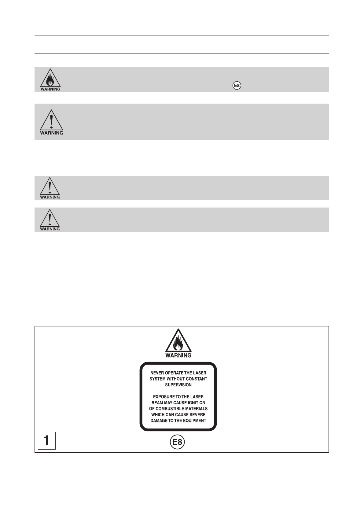
Materials
Materials for LASER engraving
Safety
NEVER LEAVE THE LASER SYSTEM RUNNING UNATTENDED FOR ANY REASON. Exposure
to the LASER beam can cause ignition of combustible materials. All LASER cutting and
engraving should be constantly supervised (Label - pict. 1).
NEVER OPERATE THE LASER SYSTEM WITHOUT A PROPERLY INSTALLED AND OPERATING
EXHAUST SYSTEM. Some materials when cut or engraved can produce fumes that are
hazardous in concentrated amounts.
Also make sure that your room is adequately ventilated as some materials will
continue to produce fumes for several minutes to possibly hours after the cutting or
engraving process has been completed.
Since many materials can produce toxic and possibly caustic fumes or residue, it is advisable to obtain the Material Safety
Data Sheet (MSDS) from the materials manufacturer.
The MSDS discloses all of the hazards when handling or processing that material. The law requires all manufacturers to
provide this information to anyone who requests it.
DO NOT ENGRAVE OR CUT PVC (Polyvinylchloride) BASED MATERIALS. The fumes are
extremely toxic if you inhale them. The fumes are so corrosive that they can chemically
destroy the metallic parts of the LASER system. Damage to the LASER system from this
type of abuse WILL NOT be covered under warranty.
DO NOT ENGRAVE OR CUT UNCOATED METALS OR REFLECTIVE SURFACES. The LASER
beam can reflect off of these materials causing damage to the LASER system as well
as being a safety hazard. Damage to the LASER system from this type of abuse WILL
NOT be covered under warranty.
NOTICE
LASER engraving or cutting materials other than those described in this manual can be a safety hazard and can damage
the LASER system.
The LASER system operator is liable for any damages caused, in whole or in part, for any economic loss, physical injury,
lost revenue, lost profits, lost savings or other indirect, incidental, special or consequential damages incurred.
Damages to the LASER system due to neglect, misuse, or operator error WILL NOT be covered under warranty.
L-SOLUTION 700 / 800 / 900 machines . 90
First contact
Page 91

Materials
Printer driver setting tips
There are many variables that can affect the cutting and engraving process such as differences in the thickness of the
material, density of the material, composition of the material, and the manufacturing processes used to make the material.
Power Setting
- Higher burns deeper. Too much power sacrifices detail. Has no effect on running time.
- Lower burns shallower. Too little power sacrifices detail. Has no effect on running time.
Speed Setting
- Higher saves time. Burns shallower and reduces detail.
- Lower increases time. Burns deeper but too deep may reduce detail.
PPI Setting
- Higher increases the burning or melting effect. Produces finer detail if Speed is not too fast. Has no effect on running
time and very little effect on depth.
- Lower decreases the burning or melting effect. Reduces image detail if set too low. Has no effect on running time and
very little effect on depth. Very low settings are used to perforate the material.
Rule of Thumb
- Doubling the Power doubles the depth and halving the Power halves the depth.
- Halving the Speed doubles the depth and doubling the Speed halves the depth.
NOTE
The LASER system can reach engraving speeds up to 78"
When engraving very small objects, this speed cannot be achieved because acceleration and deceleration of the motion
system requires time and distance. The LASER system will automatically adjust itself to a maximum engraving speed that
it can achieve due to the size and position of the graphic. This is why you might notice that there might be no difference
in engraving time on certain graphics whether you choose 100% speed or less.
3/4
inches per second (2ms-1) when set to 100% speed in the driver.
List of materials for LASER engraving:
GRAVOGLAS 1 / ACRYLIC - CAST AND EXTRUDED
GRAVOXAL / ALUMINUM - ANODIZED
GRAVOMETALL / BRASS - PAINTED
GLASS / CRYSTAL
GRAVOSTRAT / MELAMINE
RUBBALASE / RUBBER STAMPS
GRAVOLASE / GRAVOFLEX / PLASTIC - MICROSURFACED
ACRYLIC - MIRRORED
CORIAN / AVONITE / FOUNTAINHEAD
DELRIN (SEAL PRESS)
WOOD INLAYS - VENEERS
LEATHER
MARBLE
WOOD
CORK
MAT BOARD
VINYL
First contact
L-SOLUTION 700 / 800 / 900 machines . 91
Page 92

General maintenance
General maintenance
Before carrying out any maintenance, unplug the mains supply cable.
No internal part of the Gravograph machine requires user intervention : general maintenance is limited to external,
engraving work area and optics cleaning.
If you wish to have the inside of your machine cleaned, contact a Gravograph technician.
The mains cable should always be replaced if it is damaged in any way : flattened,
nicked, cracked etc..., or if there are bare wires.
Keeping the LASER system clean will ensure the highest quality engraving.
The frequency of cleaning will depend entirely on the type of material being engraved, the performance of your exhaust
blower, the operating environment, and the amount of LASER system usage over a given period of time.
Dirt or debris that is allowed to build up on the motion system components will cause uneven or rough engraving, or loss
of engraving position as well as premature component failure.
Smoke or dirt buildup on the optics can cause damage to them, loss of LASER power, or premature failure of these
components.
Use good judgment and keep in mind that a clean machine is the best performing machine.
Suggested cleaning and maintenance supplies
- Specific product for lens and mirrors cleaning (1 bottle provided with the machine)
- Soap solution mixture of 1 tablespoon (2 cl) liquid soap and 1 quart (liter) of water in a spray bottle
- Paper towels
- Cotton cloth
- Denatured alcohol (NOT to be used on any painted surface, plastic, or the Top Window)
- Acetone (can be used on the engraving table but nowhere else)
- Cotton swabs (provided with the machine)
- Lens cleaner
- Lens cleaning paper (provided with the machine)
- Vacuum cleaner
- Set of Allen wrenches sized from .050 to 3/16 inch
When using acetone or denatured alcohol, please follow the instructions on the printed
label of these materials for safe handling procedures.
Please familiarize yourself with the motion system components.
It will help you understand which components need periodic cleaning.
L-SOLUTION 700 / 800 / 900 machines . 92
First contact
Page 93

General maintenance
System cleaning
Before carrying out any maintenance, unplug the mains supply cable.
Table cleaning :
1. Turn off and unplug the LASER system.
2. Open the Front door and thoroughly remove all loose dirt and debris from inside the machine with
a vacuum cleaner.
We advise you to never use compressed air for cleaning.
3. Clean the engraving table surface with a soap solution, alcohol, or acetone, and paper towels.
NEVER pour or spray any solution directly into the LASER system. Always dampen your paper
towel or cloth outside of the machine with the cleaning solution and then wipe down the parts
you are cleaning with the dampened cloth.
4. Clean the front window with chamois leather and the soap solution. The front window is made
out of acrylic. DO NOT use paper towels because they will scratch the acrylic and DO NOT use
solvent. Also, DO NOT use window cleaner, alcohol, or acetone, as these chemicals will crack the
acrylic. Only use cleaners designed for acrylic.
5. Use a soft cloth or paper towels and the soap solution to clean the enclosure. DO NOT use alcohol,
acetone, or any other harsh chemical, as this will damage the paint.
Rails cleaning :
No cleaning by the user is necessary.
Belts cleaning :
No cleaning by the user is necessary.
Fumes exhaust inlet cleaning :
Fumes exhaust inlet cleaning is carried out with a hoover and if necessary with a brush.
First contact
L-SOLUTION 700 / 800 / 900 machines . 93
Page 94

General maintenance
L-SOLUTION 700 / 800 / 900 machines . 94
First contact
Page 95

General maintenance
Optics cleaning
A visual inspection of the mirrors, beam window, and focus lens should be performed at least once a day.
DO NOT clean a n optic that is visually clean. Excessive cleaning can damage the optics.
The focus lens and the mirrors and the beam lens should not to be removed for
cleaning.
DO NOT remove the focus lens from its support for cleaning.
Before cleaning the optics, we recommend that you wash your hands thoroughly to
prevent contamination. NEVER touch any optic with your fingers. The acids from your
skin can destroy the coatings on the optics.
Mirrors and focus lens
(pict. 1, 2 and 3)
Inspect the 2 mirrors (through the holes and ) and the lens and and clean
them only if there is debris present.
Clean them only with a lens cleaning paper, through the holes and for the
mirors.
1. Moisten the lens cleaning paper with the Lens Cleaning solution supplied with the LASER system.
DO NOT use other types of cleaners or solutions.
2. Dust the mirror or the lens once with the lens cleaning paper (diagram 3). DO NOT press too strong
the lens cleaning paper as this can scratch the mirror or the lens.
3. If the mirror or the lens did not come clean, use a lens cleaning paper and repeat the procedure.
Do not worry about small pieces of lint that come off the lens cleaning paper. They will
be vaporized as soon as the LASER hits it. You can cause more damage to the mirror
or the lens by trying to get it off than by leaving it alone.
Maintenance schedule
Since the maintenance requirements of the LASER system depend on the type of material being run, the quantity of material
being removed, the hours of operation, and the quality of the exhaust blower, maintenance must be user-defined.
As a starting point, we recommend checking and, if necessary, cleaning the LASER system after every 8 hours of engraving
or cutting.
Depending on your particular operation, you may need to adjust this schedule.
If you notice a considerable buildup of debris on the optics and the motion system, clean the system at more frequent
intervals. If your system has remained relatively clean, you can extend your cleaning intervals.
You need to be the judge but keep in mind that a clean machine is a better performing machine and can extend the life
of the parts as well as reduce the possibility of down time.
Maintaining and cleaning the LASER system should not take more than five minutes a day. If you have any questions about
maintaining the LASER system, please contact your GRAVOGRAPH dealer.
First contact
L-SOLUTION 700 / 800 / 900 machines . 95
Page 96

Autofocus adjustment
Autofocus adjustment
Do not use the controls or settings and do not carry out procedures other than those
specified in the use manual, to avoid risking exposure to dangerous radiation.
After an incident or a bad handling with the head of the LASER machine, the autofocus can go wrong .
To solve this problem, a simple procedure can be effected by the user:
1. Switch off the machine (main stop button (L) in 0 position)
2. Close the front door
3. Switch on the machine (main stop button (L) in I position)
When switched on the ventilator of the machine will start.
The following message will be displayed on the L.C.D. screen of the machine:
SET UP
FPGA X.XX
LCD SOFT X.XX
16 Mo BOOT X.X
The machine will then issue a "beep" and the following screen will remain displayed for 3 seconds:
<< GRAVOGRAPH >>
LASER VERSION X.XX
LCD SOFT X.XX
16 Mo BOOT X.X
4. While this message is displayed, press
SET LASER TYPE
TICKLE
RE-ALIGN MACHINE
5. Select the RE-ALIGN MACHINE menu using the arrows keys
SET LASER TYPE
TICKLE
RE-ALIGN MACHINE
6. Validate
RE-ALIGN X-Y
RE-ALIGN Z
ALIGNMENT MODE
7. Select the RE-ALIGN Z menu using the arrows keys
RE-ALIGN X-Y
RE-ALIGN Z
ALIGNMENT MODE
L-SOLUTION 700 / 800 / 900 machines . 96
First contact
Page 97

Autofocus adjustment
8. Validate
The head of the machine moves towards the centre of the engraving table and an autofocus is effected automatically
(pict. 1).
The following message will be displayed on the L.C.D. screen of the machine:
RE-ALIGN Z
JOYSTICK Z
Z = ZZ.ZZ
9. Open the front door of the LASER machine
10. Place the wedge for the autofocus adjustment (provided with the machine) on the engraving
table, just below the lens support of the LASER head (pict. 2)
11. Go up the engraving table until the lens support of the head touches slightly the wedge
(pict. 3) using the arrows keys
First contact
L-SOLUTION 700 / 800 / 900 machines . 97
Page 98

Autofocus adjustment
12. Before you continue, you must imperatively remove the wedge
Do not forget to remove the wedge a this time of the procedure. Otherwise, it can
severely damage the LASER machine.
13. Close the front door of the LASER machine
14. Validate
RE-ALIGN X-Y
RE-ALIGN Z
ALIGNMENT MODE
15. Exit the RE-ALIGN MACHINE menu using the key
SET LASER TYPE
TICKLE
RE-ALIGN MACHINE
16. Exit the MACHINE menu using the key
The following screen will remain displayed for 3 seconds:
<< GRAVOGRAPH >>
LASER VERSION X.XX
LCD SOFT X.XX
16 Mo BOOT X.X
The following message will be displayed. It indicates that the LASER machine is ready to receive files:
<READY TO RECEIVE>
001 FILENAME1
PUI 40 VIT 10
DPIX 400 DPIY 400
Do not use the controls or settings and do not carry out procedures other than those
specified in the use manual, to avoid risking exposure to dangerous radiation.
L-SOLUTION 700 / 800 / 900 machines . 98
First contact
Page 99
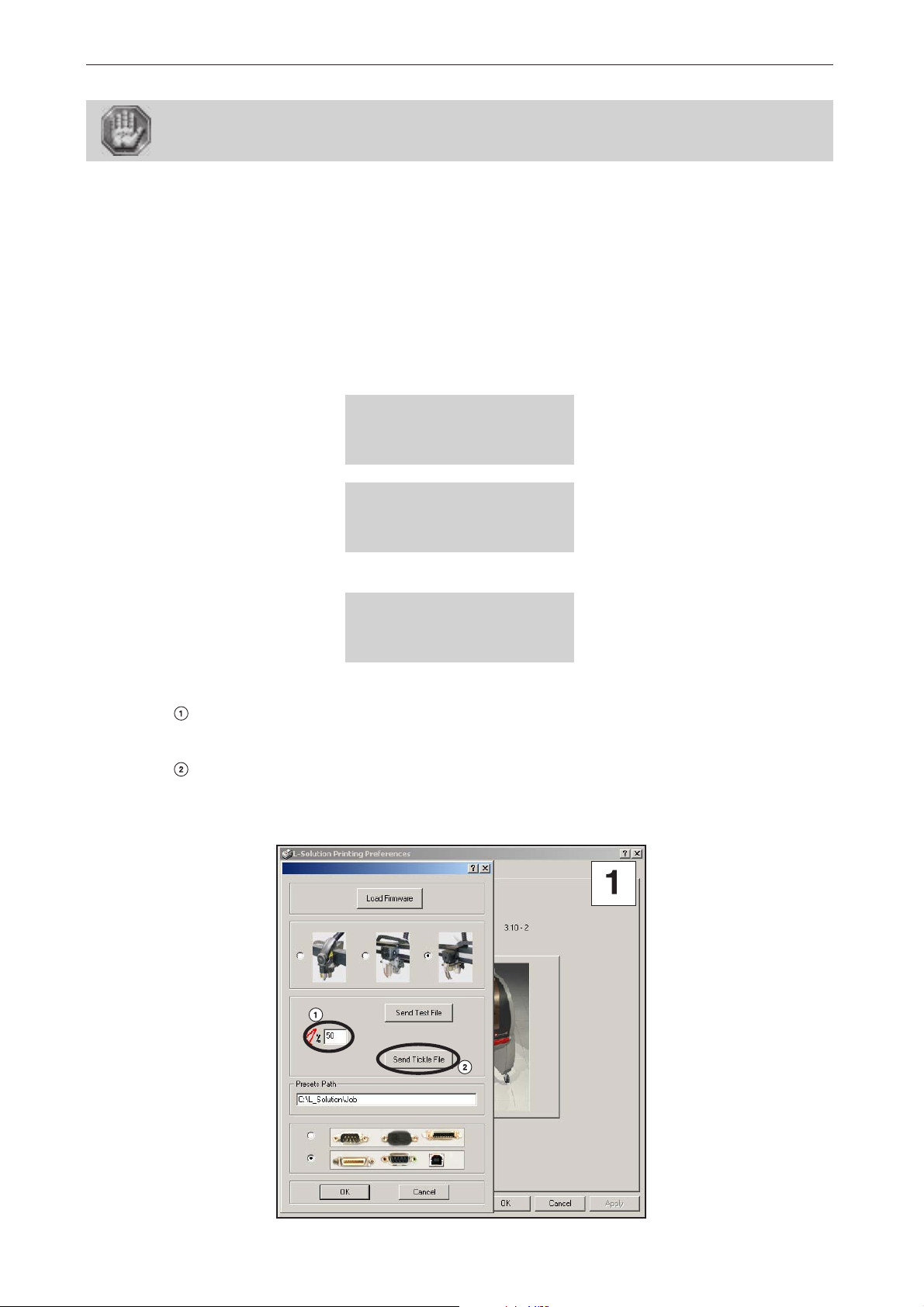
Tickle adjustment
"Tickle" adjustment
Do not use the controls or settings and do not carry out procedures other than those
specified in the use manual, to avoid risking exposure to dangerous radiation.
"Tickle" is the term used for small pulses, which are fed to the laser to keep the plasma inside energized. This allows the
laser to respond quickly and strongly for high speed cutting and engraving.
"Tickle" keeps the laser «warmed up» at times when the laser system is powered on but not firing and the top door is closed.
We suggest keeping the door closed at all times when the laser system is powered on as this keeps the laser warmed up.
If the door is open, the power to the laser tube itself is turned off and the tube will cool down. The laser runs best after
being warmed up for 15 to 20 minutes.
"Tickle" is pre-set at the factory and usually does not require adjustment. However, it is possible that it may need
adjustment after the laser system ages several years. A simple procedure can be effected by the user in order to make out
a correct diagnosis and in order to use the following corrective procedure, if necessary:
1. Switch on the machine (main stop button (L) in I position)
When switched on the ventilator of the machine will start. The following message will be displayed on the L.C.D. screen
of the machine:
SET UP
FPGA X.XX
LCD SOFT X.XX
16 Mo BOOT X.X
<< GRAVOGRAPH >>
LASER VERSION X.XX
LCD SOFT X.XX
Wait a few seconds.
The following message is displayed on the screen:
16 Mo BOOT X.X
<READY TO RECEIVE>
001 FILENAME1
PUI 40 VIT 10
DPIX 400 DPIY 400
2. Start the engraving of the "Tickle" engraving test file.
- Adjust the power of your laser based on the material used for engraving the test file.
We advise you to use an engraving material sensitive to the LASER radiation as Gravoglas.
- Select "Send Tickle File" (from the "About of" tab) to transfer the test file to the
machine:
First contact
L-SOLUTION 700 / 800 / 900 machines . 99
Page 100

Tickle adjustment
- Start the engraving.
12 lines (numbered from 1 to 12) are then engraved:
3. Select the number of the engraved line which does not show LASER impact marks outside the
engraving and which is just before a line where appear these marks.
(for example the #4 line) :
4. Switch off the machine (main stop button (L) in 0 position)
5. Close the front door
6. Switch on the machine (main stop button (L) in I position)
When switched on the ventilator of the machine will start.
The following message will be displayed on the L.C.D. screen of the machine:
SET UP
FPGA X.XX
LCD SOFT X.XX
16 Mo BOOT X.X
The machine will then issue a "beep" and the following screen will remain displayed for 3 seconds:
<< GRAVOGRAPH >>
LASER VERSION X.XX
LCD SOFT X.XX
16 Mo BOOT X.X
7. While this message is displayed, press
SET LASER TYPE
TICKLE
RE-ALIGN MACHINE
Do not use the controls or settings and do not carry out procedures other than those
specified in the use manual, to avoid risking exposure to dangerous radiation.
L-SOLUTION 700 / 800 / 900 machines . 100
First contact
 Loading...