

Page 1
Before installing and using this
machine, you must read this user
guide carefully. Keep it in a safe
place, in case you need to refer to
it later.
This manual should not be used
without the CN 97 program manual
- B2241 701.
D2083 701 - 02.2008 - ENG - (UPDATED EDITION NUMBER: 10)
(Please read carefully
before use)
User manual
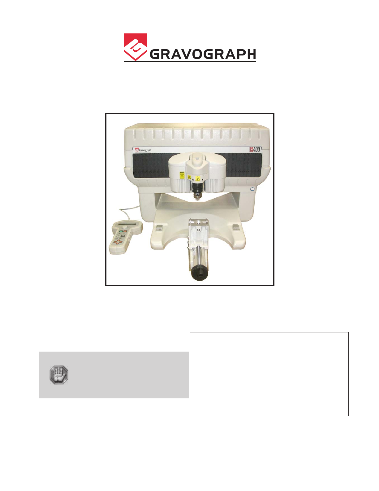
IS400 machine
First contact
Page 2

IS400 machine . 2
First contact
Gravograph reserves the right to modify the information contained in this document without notice.
TYPE OF MACHINE : IS400 Electronic Engraving Machine
MANUFACTURER : GRAVOGRAPH INDUSTRIE INTERNATIONAL
BP 15 - Z.I. - 10600 LA CHAPELLE SAINT LUC - FRANCE
(c) Gravograph Industrie International, 2008
All Rights Reserved.
Importer's address
This publication and its contents are proprietary to Gravograph Industrie International (Gravograph), and are intended
solely for the contractual use of Gravograph customers.
While reasonable efforts have been made to assure the accuracy of this manual, Gravograph shall not be liable for errors
contained herein or for incidental or consequential damage in connection with the furnishing, performance, or use of this
material.
Gravograph reserves the right to revise this manual and make changes from time to time without any obligation by
Gravograph to notify anybody of such revision or changes.
Gravograph can not be held liable for any problems arising out of the application or use of any products, circuits, or software
described herein. Neither does it convey a license under its patent rights nor the patent rights of third parties.
Gravograph provides no warranties whatsoever on any software used in connection with a Gravograph Engraving System,
express or implied. Neither does it guarantee software compatibility with any off-the-shelf software package or any software
program that has not been written by Gravograph.
Intended use of this system must be followed within the guidelines of this manual. In no event will Gravograph be liable
for any damages caused, in whole or in part, by customer, or for any economic loss, physical injury, lost revenue, lost profits,
lost savings or other indirect, incidental, special or consequential damages incurred by any person, even if Gravograph has
been advised of the possibility of such damages or claims.
Windows is a registered trademark of Microsoft Corporation.
PostScript is a registered trademark of Adobe Systems Inc.
Page 3

First contact
IS400 machine . 3
Summary
Information about regulations ............................................................ 4
Conformity standards ...................................................................................................................... 4
Electrical security ........................................................................................................................... 4
Presentation ....................................................................................... 5
Contra-indications .......................................................................................................................... 5
Stages of unpacking ....................................................................................................................... 6
Unpacking - Contents of package ...................................................................................................... 7
Description ......................................................................................... 9
Front view of the machine ............................................................................................................... 9
Vice ............................................................................................................................................ 11
Long plate support kit ................................................................................................................... 12
Rear view of the machine .............................................................................................................. 13
Installing .......................................................................................... 14
Physical installation advice ............................................................................................................. 14
Electric installation advice .............................................................................................................. 15
Electrical connections of the machine .............................................................................................. 16
Connecting the IS400 machine to a PC ........................................................................................... 17
Switching the machine on .............................................................................................................. 20
Problems ..................................................................................................................................... 20
Switching the machine off ............................................................................................................. 20
Mechanical block .......................................................................................................................... 20
Switching on again ....................................................................................................................... 20
Machine configuration (language) ................................................................................................... 21
Installing the engraving software in Windows XP .............................................................................. 23
Engraving ......................................................................................... 24
Positioning the plate onto the vice .................................................................................................. 24
Point and Shoot ........................................................................................................................... 25
Transfer procedure ....................................................................................................................... 26
Adjusting the spindle .................................................................................................................... 27
Adjusting the rotation speed on the spindle ...................................................................................... 31
Starting to engrave ...................................................................................................................... 32
General maintenance ........................................................................ 33
Changing the belt ......................................................................................................................... 33
Adjusting the machine .................................................................................................................. 34
Technical Characteristics .................................................................. 36
Physical Characteristics ................................................................................................................. 36
Electrical Characteristics ................................................................................................................ 37
Engraving software characteristics .................................................................................................. 37
Optional accessories ..................................................................................................................... 38
Page 4
IS400 machine . 4
First contact
Information about regulations
Conformity standards
This hardware was designed and built in conformity with the relevant EC marking and EEC directives :
• "Security" Directive 98/37/EEC (22/06/98).
• "Electromagnetic compatibility" Directive 2004/108/EC
• "Low voltage" Directive 2006/95/EC
The modification or transformation of this equipment, the adaptation and installation
of accessories not recommended by GRAVOGRAPH, the installation of this equipment
in a manufacturing process, the piloting by a robot, the connection to an external
automaton, modify the characteristics of this material and can make it not compliant
with the European Directives it is subjected.
These modifications voids the responsibility of the manufacturer.
In this case, the person who fits the machine and the equipment is responsible for the
EC compliance of the final work station.
Electrical security
This hardware is in conformity with the norms EN 60204-1 and EN 60950-1, which also refer to the LASER system safety
standard CEI 825-1 (08/2001).
The different fuses of the machine comply with the IEC 127-2 norm (International Electric Committee).
The different security levels the input/output answer are indicated for each connector in the chapter "Rear view of the
machine". Two security levels are possible :
- Dangerous voltage (power supply, accessories, plugs ...).
- Very low security voltage.
Machine security
This hardware is in conformity with the norm EN ISO12100-1 and EN ISO12100-2.
Electromagnetic compatibility
This hardware is in conformity with electromagnetic compatibility norms:
• EN 55022 - class B ; EN 61000-3-2 ; EN 61000-3-3 (emission in residential, commercial, and light industrial environment)
• EN 61000-6-2 (immunity in industrial environment)
All the cables used with this hardware must be in conformity with the electronic compatibility standards, norm
EN 55022 - class B.
Electrical security
This material is «class 1». The mains plug MUST always be connected to a neutral
socket and comply with the regulations in force in the country of installation. If you
do not have a plug of this type, have one installed by an approved electrician. Under
no circumstances should you depart from this instruction.
The manufacturer bears no responsibility towards any user where alterations have been carried out contrary to the
manufacturer's specifications, notably with respect to electrical/electronic elements.
Any operation, other than those mentioned here, must only be carried out by an
approved Gravograph technician.
Do not take the machine apart to repair or clean it : this will void your guarantee.
This symbol indicates that once this equipment has reached the end of its useful life,
it must not be disposed of with non-sorted municipal waste, in accordance with the
European Directive 2002/96/EC.
The equipment must be disposed of at an appropriate collection point for processing,
sorting, and recycling of Waste Electrical and Electronic Equipment (DEEE).
The elements which compose Electrical and Electronic Equipment may contain
substances which have harmful effects on the environment or on human health.
By following these instructions, you are helping the environment, contributing to the
preservation of our natural resources, and protecting human health.
Page 5
First contact
IS400 machine . 5
Presentation
The machine must never be handled without an adult present. Keep the machine,
wires and cables out of children's reach.
Contra-indications
This machine is only designed for light engraving purposes and must never be used for
other applications.
To use this machine, you are advised to wear protectives glasses against the chip
ejections.
Never use this machine for sawing or drilling.
Do not use this machine for working with wood.
Do not use this machine in explosive environment.
This machine is only designed for one user. Do not let several people use the machine
simultaneously.
• If the machine is not to be used for a long period, unplug the electricity supply and cover the machine (packaging, cover,
lid...).
• Do not move the engraving head by hand unless mechanical block of the machine as described in the paragraph
"Mechanical block" of this manual's "Installing" chapter.
• Do not spill any liquids onto the machine (drinks, cleaning fluids…) unless when recommended by GRAVOGRAPH
(example: lubrication).
• Do not place any object on the machine other than that to be engraved.
• The machine should never be used with anything other than Gravograph accessories and tools.
• Never hold the material to be engraved in your hands. Only use the GRAVOGRAPH clamping systems designed for your
machine.
• Make sure that the material is well clamped before starting to engrave.
• During engraving, do not use this machine without a nose (depth regulating nose or vacuum nose) in order to avoid
projections of swarf.
• Do not take the engraving material out of the machine during engraving.
• If the engraving must be stopped, use the function key provided for this purpose on the keyboard of the machine.
To avoid any risks of being crushed by the machine during engraving, do not stand near
the tools (the travel area of the tool is 305x210mm).
Do not lean over the spindle holder.
Ensure that no one is in the travelling area of the moving parts of the machine and that
no object will obstruct the travelling of the moving parts.
This sign shown on the tool-holder of the machine shows the danger
caused by the rotating spindle during engraving (risks of getting burnt
or cut).
To avoid any risks of getting burnt, the protective belt housing of the
tool-holder must be always closed, except when carrying out adjustments.
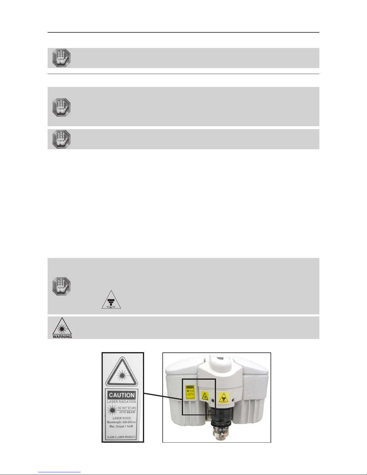
CAUTION - LASER RADIATION (pict. 2)
Do not stare into beam
Laser diode - Wavelength: 630-680nm - Max. Output < 1mW
CLASS 2 LASER PRODUCT
Page 6
IS400 machine . 6
First contact
Stages of unpacking
Two people are necessary to unpack the IS400 machine.
Before opening the cardboard box, check that it is the right way up.
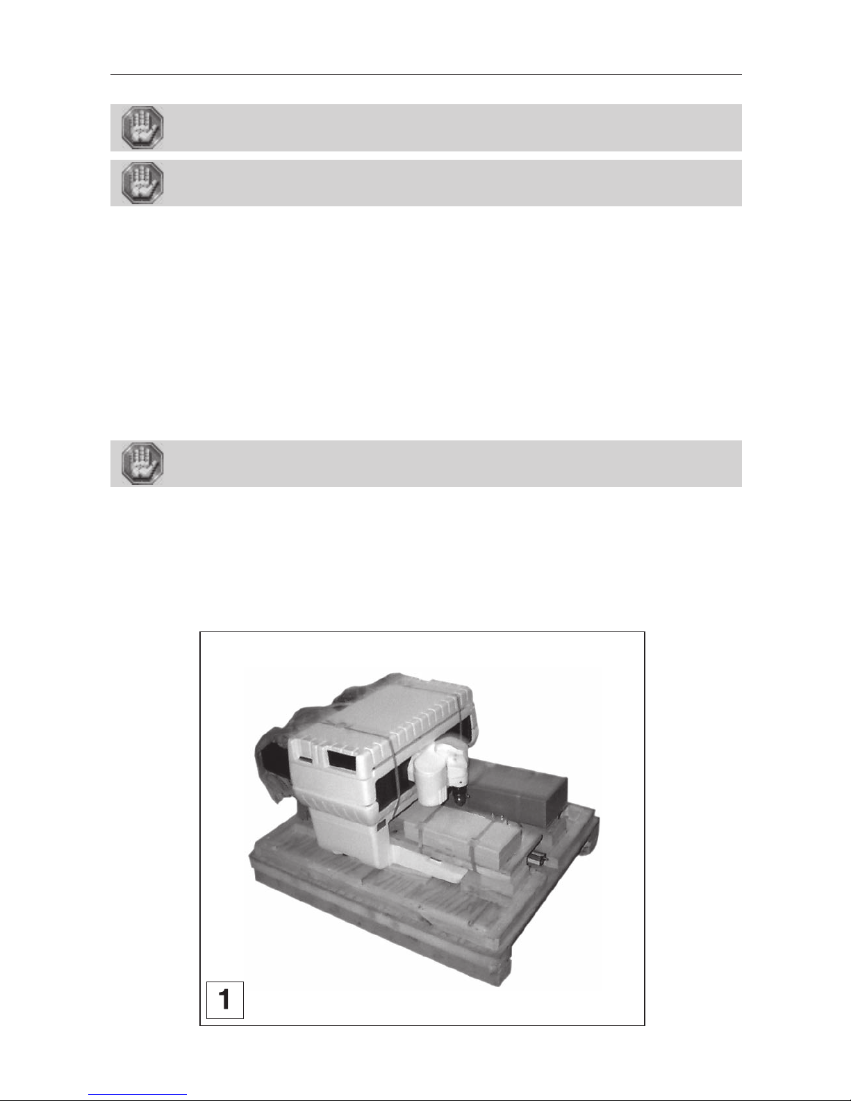
After opening the box (pict. 1):
1. Take out the documents.
2. Take off the protective packaging
3. Take out the tool box.
4. Take out the cables.
5. Take off any protective packing from the machine.
6. Take out the machine.
- There should be one person on each side of the machine.
- Both should lift the machine simultaneously, and place it on the working surface.
Make sure that no components are missing from the packaging. If any part has been
forgotten please get in touch with your GRAVOGRAPH dealer.
Keep all the packaging materials so that you can move your machine in total safety. This packing was conceived to guarantee
the protection of the machine during its transport (for a return in repair for example).
This packaging is in conformity with European recycling standards.
Page 7
First contact
IS400 machine . 7
Unpacking - Contents of package
Check the condition of the packaging when you receive it. If there are any signs of
damage, inform the carrier and your GRAVOGRAPH dealer immediately by recorded
delivery, specifying the exact nature of the problem.
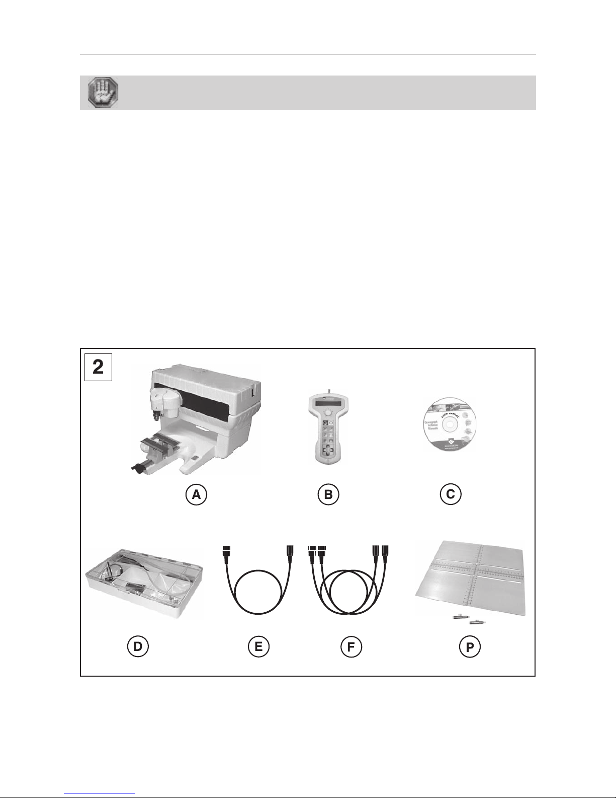
Contents of package
(pict 2)
A. An IS400 machine (IS400 electronics box + engraving table)
B. A control panel
C. A CD-Rom contains the user manual
D. A tool box
E. A power cable
F. 2 connection cables :
- an USB connection cable
- an engraving table - IS400 electronics box connection cable
P. One long plate support kit (installing page 12)
Page 8
IS400 machine . 8
First contact
3,5
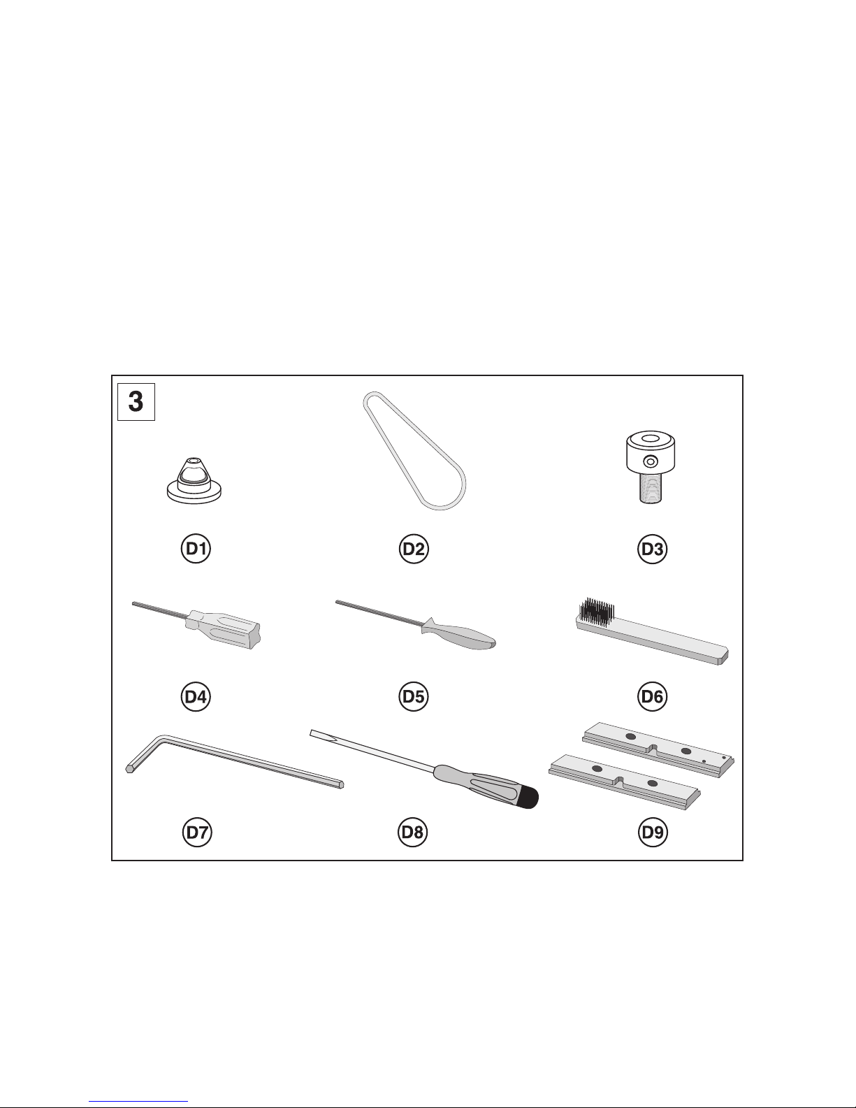
Contents of tool box
(pict 3)
D1. a depth-regulating nose
D2. a spindle belt
D3. a cutter knob
D4. a short allen key
D5. a round allen key
D6. a brush
D7. a key
D8. a screwdriver (3,5)
D9. a pair of standards jigs
Page 9
First contact
IS400 machine . 9
Description
The IS400 machine is an electronic engraving machine.
It has a keyboard, and a control panel with a L.C.D. screen connecting the software which is in the machine.
Files to be engraved are transferred from the computer to the machine by the intermediary of a cable which is plugged into
one of the two ports on the IS400 machine.
The actual engraving process is controlled by the spindle.
The object to be engraved is held in the vice (as standard) or by any other system recommended by GRAVOGRAPH (consult
your GRAVOGRAPH dealer for more information on systems available).
The IS400 machine has a maximum engraving surface area of 305x210 mm.
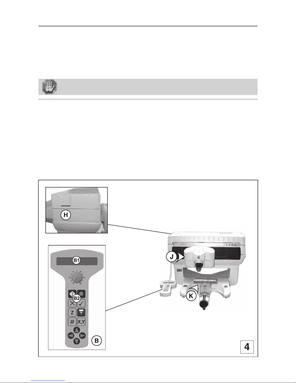
Front view of the machine
(pict 4)
B. Control panel
B1. L.C.D. screen
B2. 12-key control keyboard
H. Memory-card connector
J. Ensemble tool holder
K. Vice with pair of jaws
Page 10
IS400 machine . 10
First contact
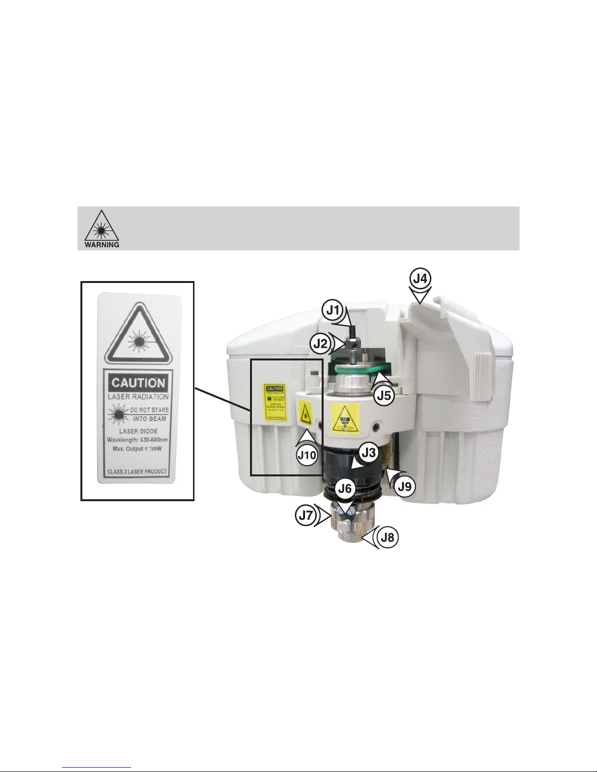
Tool holder
J1. Cutter
J2. Cutter button
J3. Pressure knurl on spindle
J4. Belt housing
J5. Belt
J6. Index finger
J7. Scaled knob
J8. Nose nut
J9. Auto ZRef switch
J10. LASER diode
CAUTION - LASER RADIATION
Do not stare into beam
LASER diode - Wavelength: 630-680nm - Max. Output < 1mW
CLASS 2 LASER PRODUCT
Page 11
First contact
IS400 machine . 11
Vice
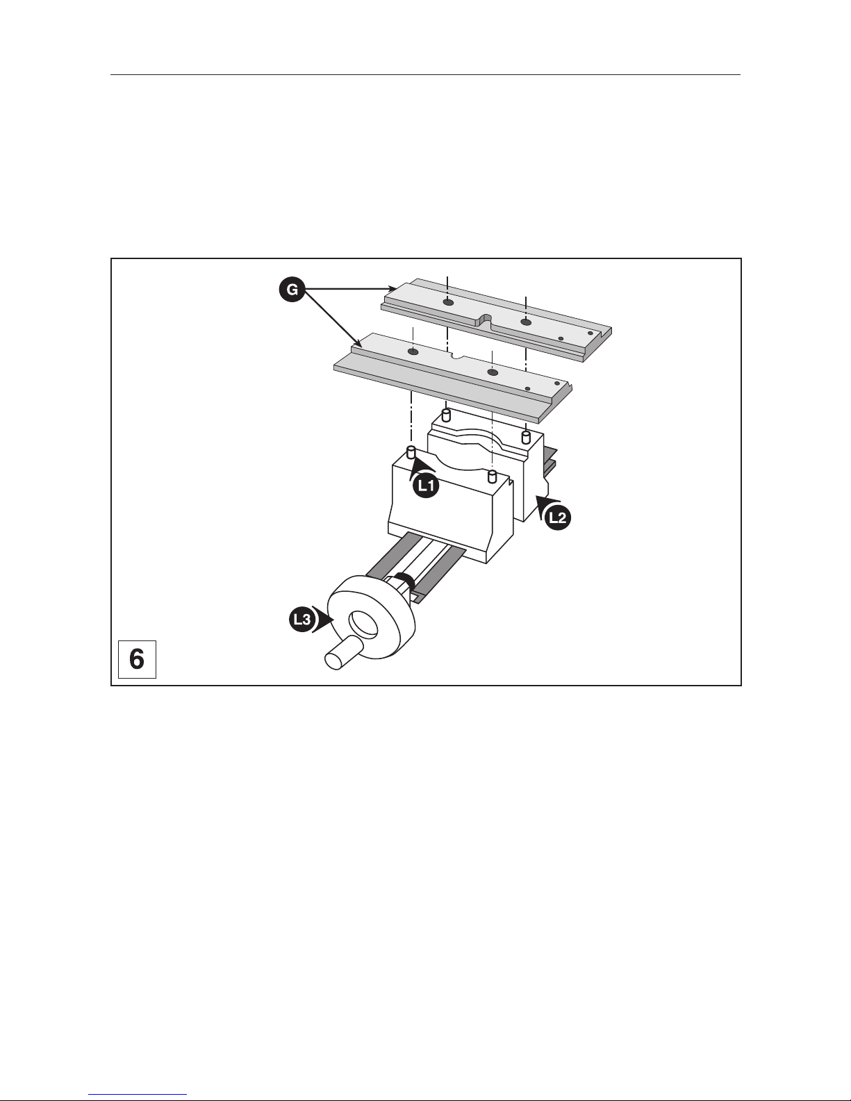
The vice holds the material to be engraved (pict 6).
The IS400 machine is supplied with a pair of jigs (G) which should be mounted onto the vice.
1. Open the jaws (L2) by turning the tightening knob (L3) anti-clockwise.
Open them far enough so as to mount the jaws easily.
2. Push the jigs (G) firmly onto the pins (L1) of the jaws (L2).
Page 12
IS400 machine . 12
First contact
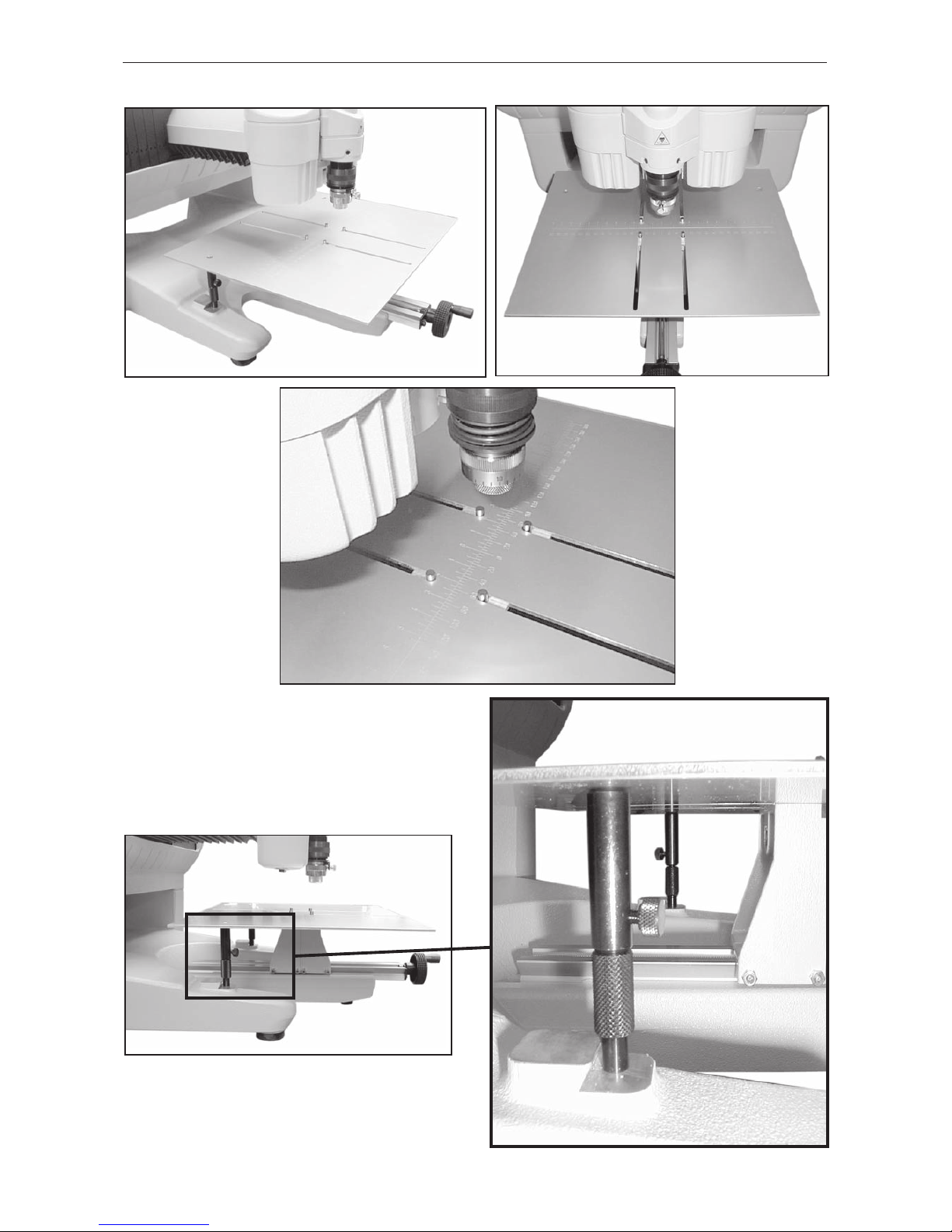
Long plate support kit
Page 13
First contact
IS400 machine . 13
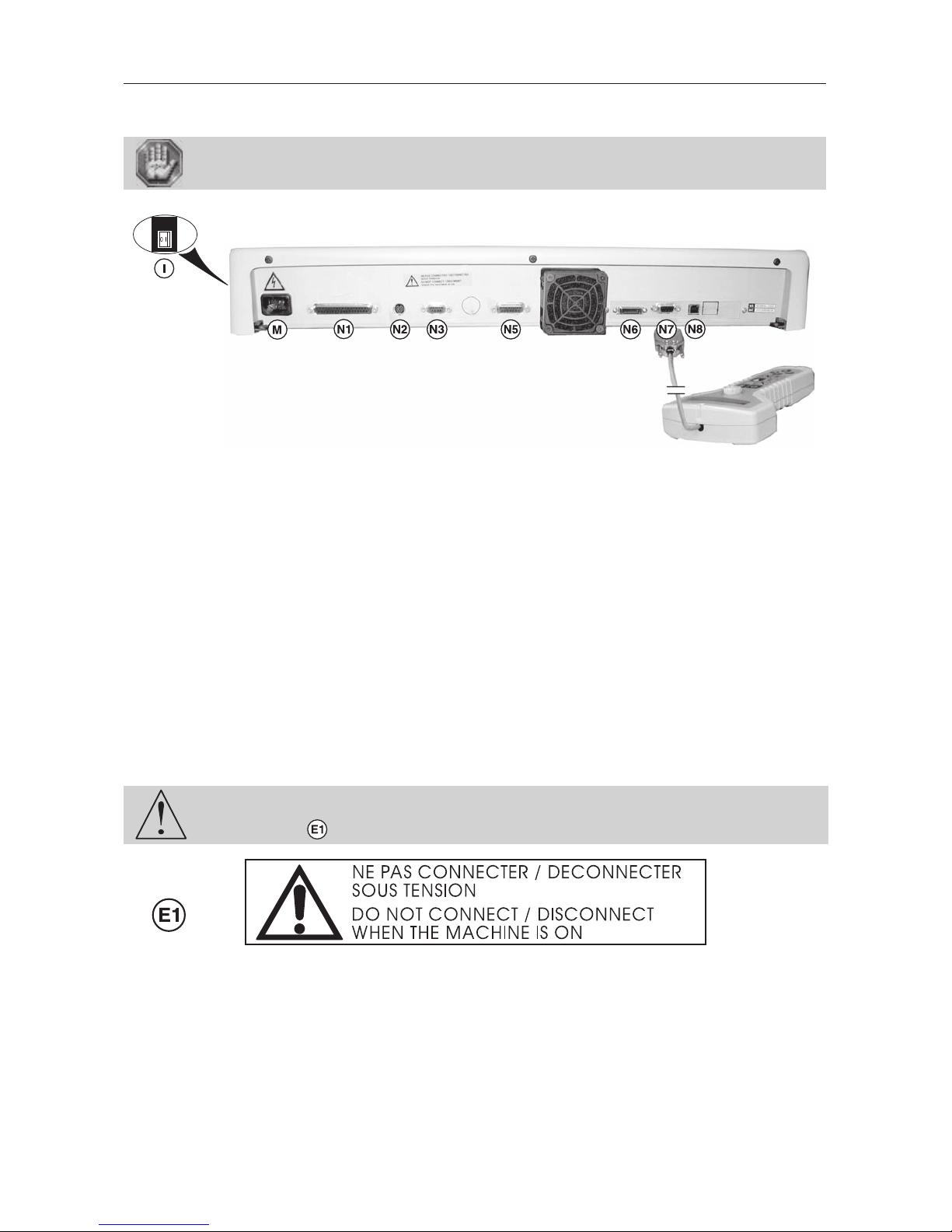
Rear view of the machine
Each connection responds to one of the following security levels :
- Dangerous voltage.
- Very low security level.
I. Switch I/0 (ON/OFF) used as an immediate stop
M. Mains supply plug - Dangerous voltage
N1. Links the machine with the electronics box - Very low security level
N2. Pen attachment/cylinder attachment - Very low security level
N3. Standard Inputs /Outputs - Very low security level
N5. External spindle Inputs /Outputs - Very low security level
N6. Parallel port - Very low security level
N7. Connection to the control panel - Very low security level
N8. USB port - Very low security level
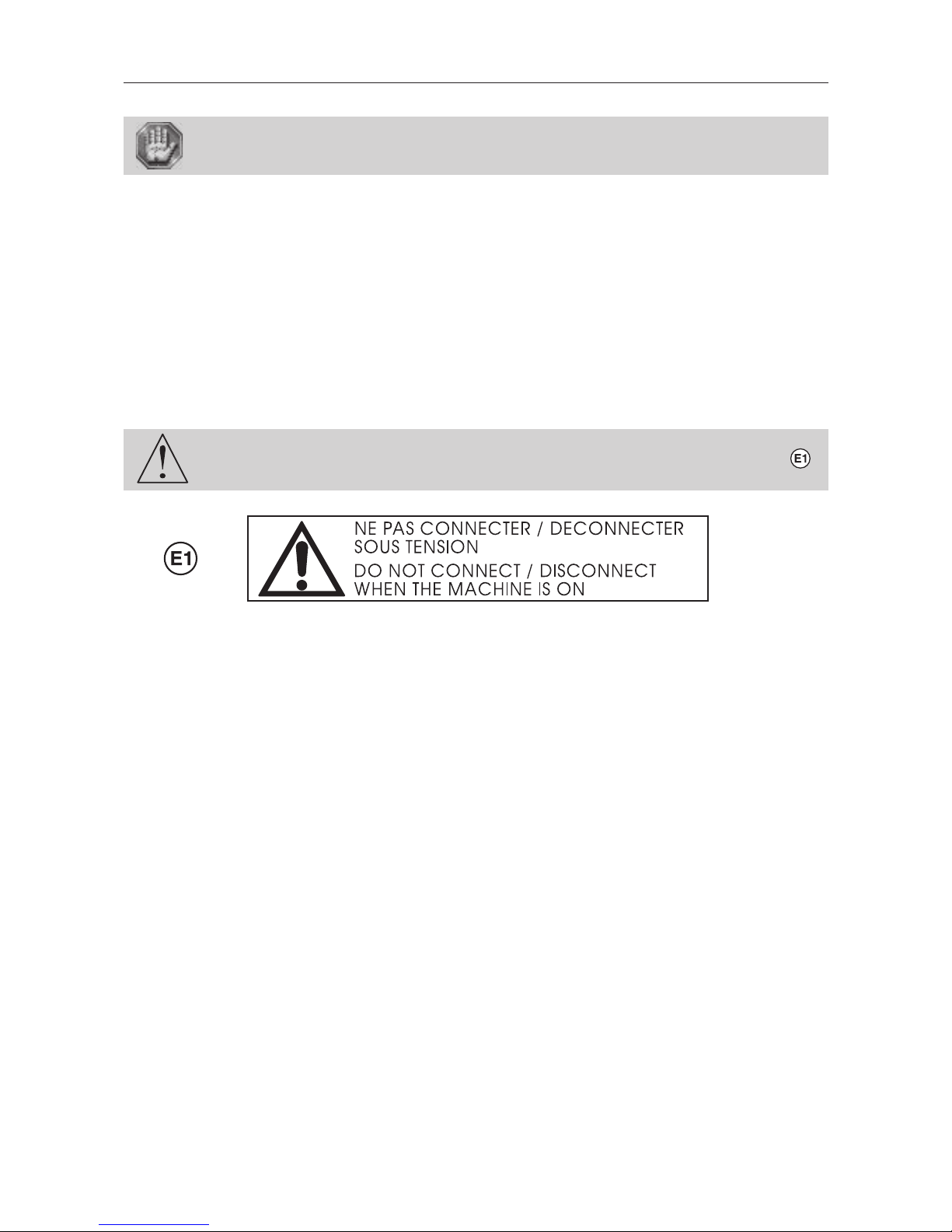
The machine must always be switched off before connecting or disconnecting a cable,
the cylinder attachment and the pen attachment (optional accessories), as indicated
on label displayed on the back of the electronic box and of the machine :
Page 14
IS400 machine . 14
First contact
Installing
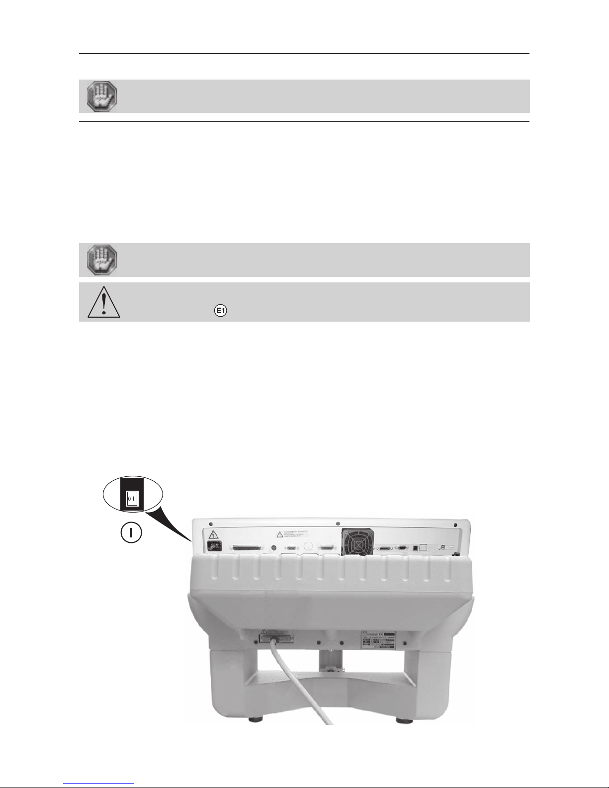
Before carrying out the following operations, make sure the machine is switched off
and unplugged, switch (I) to position 0.
Physical installation advice
• Put the Gravograph machine onto a stable flat, clean surface with mini. sizes of 520x500 mm.
Make sure the back of the machine is well-ventilated, do not put it too close to anything (wall, other machines etc).
• Clear the work surface so that you can
- easily and quickly access all external parts of the machine,
- quickly access, in case of necessity, the stop switch ON/OFF (I) at the right side of the machine,
- make sure that all moving parts of the machine have enough room to move freely,
- avoid any accidental unplugging of the cables.
The machine's power supply cable being used as a sectionning device, it must be easily
accessible and the wall plug must be installed near the machine and must also be easily
accessible.
The connectors screws must be very tight to avoid accidental disconnection of the
cables while the machine is turned on as this could permanently damage the electronic
cards (label ).
• Protect Gravograph equipment against:
- Moisture (rain, snow, condensation…),
- Heat (direct sunlight, heating…),
- Brusque temperature changes,
- Dust (exhaust pipe),
- Liquid splashes, spillages on the electronic rack, cables and connections, and any other part of the machine;
unless recommended by GRAVOGRAPH (ex. : lubrication)
- Vibrations,
- Electric or electronic radiation.
Page 15
First contact
IS400 machine . 15
Electric installation advice
This material is «class 1». The mains plug MUST always be connected to a neutral
socket and comply with the regulations in force in the country of installation. If you
do not have a plug of this type, have one installed by an approved electrician. Under
no circumstances should you depart from this instruction.
In order to avoid outside interference, the user is advised to carry out the following points.
• Plug the Gravograph machine into a mains line, avoiding having several machines on the same line (several plugs on the
same line or using a multi-plug).
Exception : If other things are connected to the machine (such as a computer or an ISIS console
linked to an IS table), the machines should be connected to the same mains line.
• Avoid using the same line to supply inductive or capacitive machines as well as the Gravograph machine (motors,
electrosluices, chargers...).
• Avoid using a manual or automatic commutator on the same mains line as the Gravograph machine (relay, temporiser,
programmer, automatic circuit interrupter, automatic interrupter...).
• Check that machines surrounding your Gravograph machine are in conformity to the norms of radioelectric perturbation
emissions (consult the technical leaflet of each machine). If they are not in conformity, place them as far away as possible
from the Gravograph machine.
• Only use Gravograph accessories (Gravograph relay box, etc ...).
The machine must always be switched off before connecting or disconnecting a cable,
the cylinder attachment and the pen attachment (optional accessories) (label ).
Page 16
IS400 machine . 16
First contact
Electrical connections of the machine
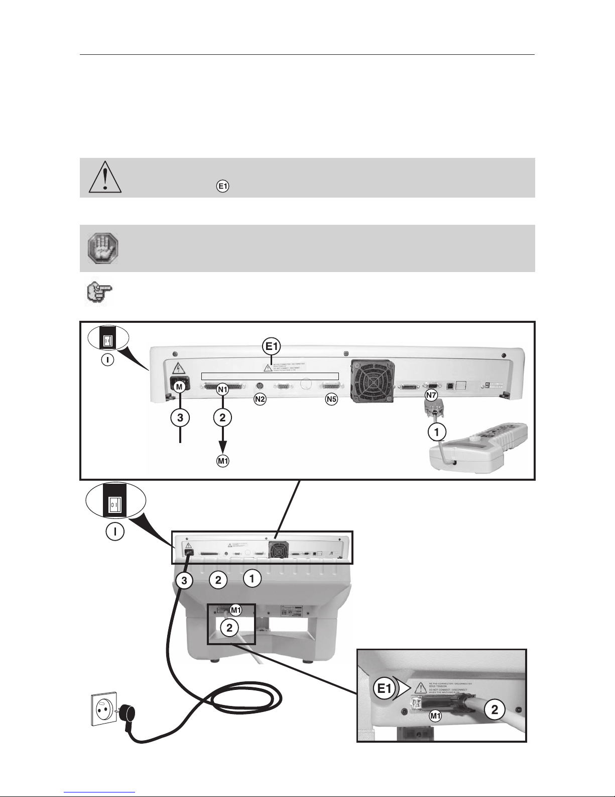
Stand behind the machine (Pict).
1. Position the control panel beside the machine.
2. Plug the control panel cable (1) into the corresponding socket (N7).
3. Plug the electronics box to the machine with the cable (2) into the correct socket (N1) and (M1).
Tighten the screws using the screwdriver (3.5).
The connectors screws must be very tight to avoid accidental disconnection of the
cables while the machine is turned on as this could permanently damage the electronic
cards (label ).
4. Plug in the electric cable (3), first to the machine, then to the mains supply.
To cut off the mains supply to your machine in the case of severe problems, unplug the
mains cable (3) or swith off the machine with the stop switch (I) at the right side of
the machine. Make sure that you can reach them easily.
As the electrical plug acts as a sectioning device, it is important you set up the machine
so that you always have easy access to the power cable.
The connector (N2) (for the cylinder attachment and the pen attachment) and the
connector (N5) (for the Automaton function) are also present at the back of the
machine.
Liaison boitier électronique/machine
Electronics-machine connection
Verbindung Elektronikeinheit/Maschine
Tourne Cylindre
Cylinder attachment
Abrollvorrichtung
Broche externe
External Spindle
Externe Spindel
E/S Standard
Standard I/O
E/A Standard
Page 17
First contact
IS400 machine . 17
Connecting the IS400 VOLUME machine to a PC
The computer and the IS400 machine must be switched OFF.
PC computers and the WINDOWS® graphic environment being very widespread
throughout the world, we have based ourselves on these products to define the
installation and use procedures of the IS400.
If you don't have equipment which is compatible and you encounter some problems of installation or use, contact your
Gravograph agent.
Connection cables
• Use Gravograph connection cables (consult your Gravograph distributor for the products available).
These cables are adapted for the machines to which they will be connected.
They must be in conformity with the electromagnetic compatibility standards, norm EN 55022 - class B and protect from
external electric "attacks" (conform to the norms of immunity and CEM susceptibility).
• Do not use cables which are too long. Keep the machines as close as possible and use a short a cable as possible.
• Separate the mains cable and the transmission cable (avoid connecting the transmission and mains cables to the same
socket, etc ...).
Follow the connection procedure depending on the transmission cable supplied with the IS400.
The machine is delivered with the following cables :
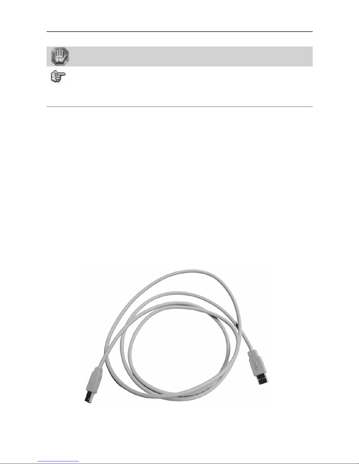
• USB cable
Page 18
IS400 machine . 18
First contact
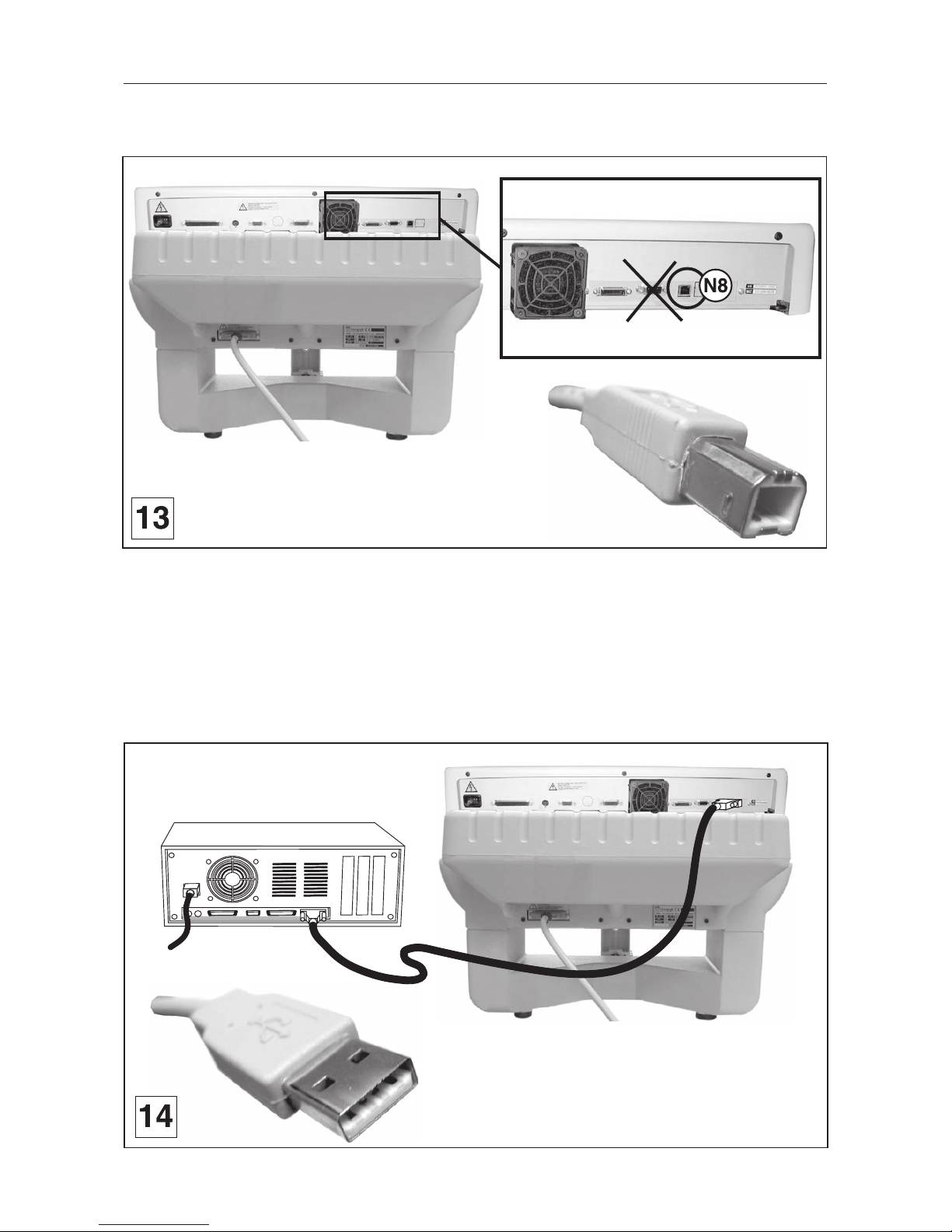
PC/IS400 connection using the USB port
1. Plug the USB cable into the USB (N8) port of the IS400 machine (diagram 13).
2. Plug the USB cable into the USB port of the PC (pict. 14).
Refer to the installation manual of the computer for the USB port (1.1).
Page 19
First contact
IS400 machine . 19
PC/IS400 connection using the parallel port
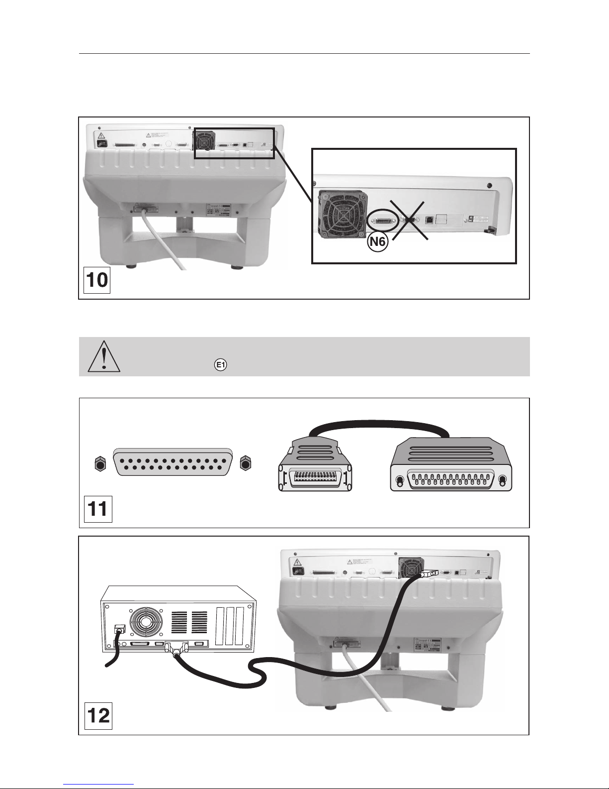
1. Plug the parallel cable (not supplied) into the parallel port (N6) of the IS400 machine
(diagram 10).
This is a 26-pin Mini-Delta Ribbon connector.
2. Plug the parallel cable (not supplied) into the parallel port of the PC (diagrams 11 and 12).
Refer to the installation manual of the computer for the parallel port.
The connectors screws must be very tight to avoid accidental disconnection of the
cables while the machine is turned on as this could permanently damage the electronic
cards (label ).
1
25
IS400
PC
1
25
Page 20
IS400 machine . 20
First contact
Switching the machine on
Switch on the machine (switch to position I).
When switched on the ventilator of the machine will start.
The following message will be displayed on the L.C.D. screen of the machine :
Boot Program X.X
RAM: 2M
The machine will then emit a "beep" and a new message will be displayed :
<< GRAVOGRAPH >>
VERSION XX.XX
Leave the machine plugged in even if it is not in constant use.
Problems
If one of the operationan signs is absent, check the following points :
• Are the twoo ends of the mains cable correctly connected ?
• Is the mains plug connected ? Is it live ?
If the machine does not come on, before calling a technician, please check power
connections to the mains socket.
Switching the machine off
Switch the switch ON/OFF (I) to position 0.
Switch off the machine for the following reasons :
- if you are leaving the workstation (end of the day, for example),
- physical damage (fall, fire, liquids coming into machine…),
- mechanical/electrical/electronic faults, leading to a possible breakdown,
- in case of major problem or mechanical block of the machine,
- to reboot,
- for external cleaning.
Mechanical block
In the following cases :
- danger for the operator,
- block on the support to be engraved,
- block on an object placed in the work area,
1. Cut the power supply by switching the switch ON/OFF (I) to position 0.
2. Free the tool, without switching the machine on, by manually and slowly moving the tool holder
as required.
3. Only switch the machine back on after ensuring that the tool's moving area is totally clear.
Switching on again
If the machine or the programme which runs it crashes you may have to reboot the machine.
If this happens, switch the machine off. Wait 30 seconds and switch it on again.
You must wait for 30 seconds. This time allows any electric shock to the machine,
possibly damaging the power supply, to be avoided.
Page 21
First contact
IS400 machine . 21
Machine configuration (language)
1. Switch on the IS400 machine (switch in position 1).
A first message will be displayed on the screen :
Boot Program X.X
RAM : 2M
A new message will be displayed on the L.C.D. screen of the machine :
<< GRAVOGRAPH >>
VERSION XX.XX
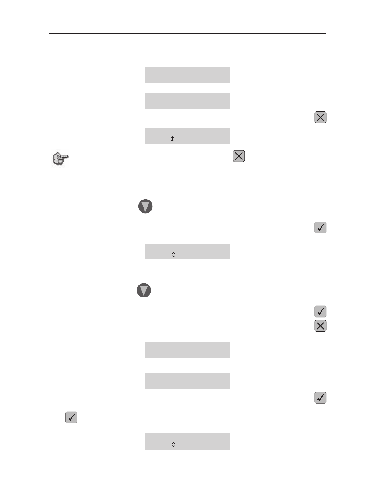
This message will be displayed for about 3 seconds. During that time press
LANGUAGE : ENGLISH
to modify
If this screen does not appear after having pressed , switch the IS400 machine off,
wait a few seconds, switch it on again, then start the configuration procedure from the
beginning.
2. Select the language desired.
When you receive your IS400 machine it is configurated to display the messages in English.
To choose the language desired press as many times as necessary.
The selected language is displayed on the screen.
To validate your choice press
The following message is displayed on the L.C.D. screen :
IS400
to select
3. Select the IS400 machine
The programme used by the IS400 machine is also used by other GRAVOGRAPH machines.
To choose the machine desired press as many times as necessary.
The selected machine is displayed on the screen.
To validate your choice press
Press
The following message is displayed on the L.C.D. screen :
<< GRAVOGRAPH >>
VERSION XX.XX
Wait a few seconds.
The following message is displayed on the screen :
<READY TO RECEIVE>
Press
Release the key when the tool-holder of the IS400 machine starts to move.
Press again.
Release the key when the following message appears :
SAVE CONFIGURATION
to select
Page 22

IS400 machine . 22
First contact
Press
The following message appears :
SAVE CONFIGURATION
to confirm
Validate by pressing
SAVE CONFIGURATION
Saving
The message on the screen indicates that the message that you have carried out is being saved. In this way the display
language that you have just chosen will be taken into account each time you switch the machine on.
3. Switch the machine off.
Page 23
First contact
IS400 machine . 23
Installing the engraving software in Windows XP ®
1. Check that your computer has the minimum required configuration :
PC Computer Configuration
Microprocessor Pentium III
Frequency 800 Mhz
Random Access Memory (RAM) 128 Mo
1 internal hard disk 10 Go with 100 Mo free
1 internal CD-ROM drive x24
1 internal 3"
1/2
disk floppy drive
1 mouse Windows compatible
1 keyboard extended (105 keys)
LPT parallel port 1
USB port (1.1 or 2.0) 1
1 graphic board 32000 colors, 16 bits
1 SVGA color monitor 15", 800x600 resolution
Software environment Windows XP
Internet Explorer 5 (or more)
Acrobat Reader 5 (or more)
Microsoft Word 2000 (or more)
Windows Media Player
Polices Arial, Microsoft Sans Serif, Verdana
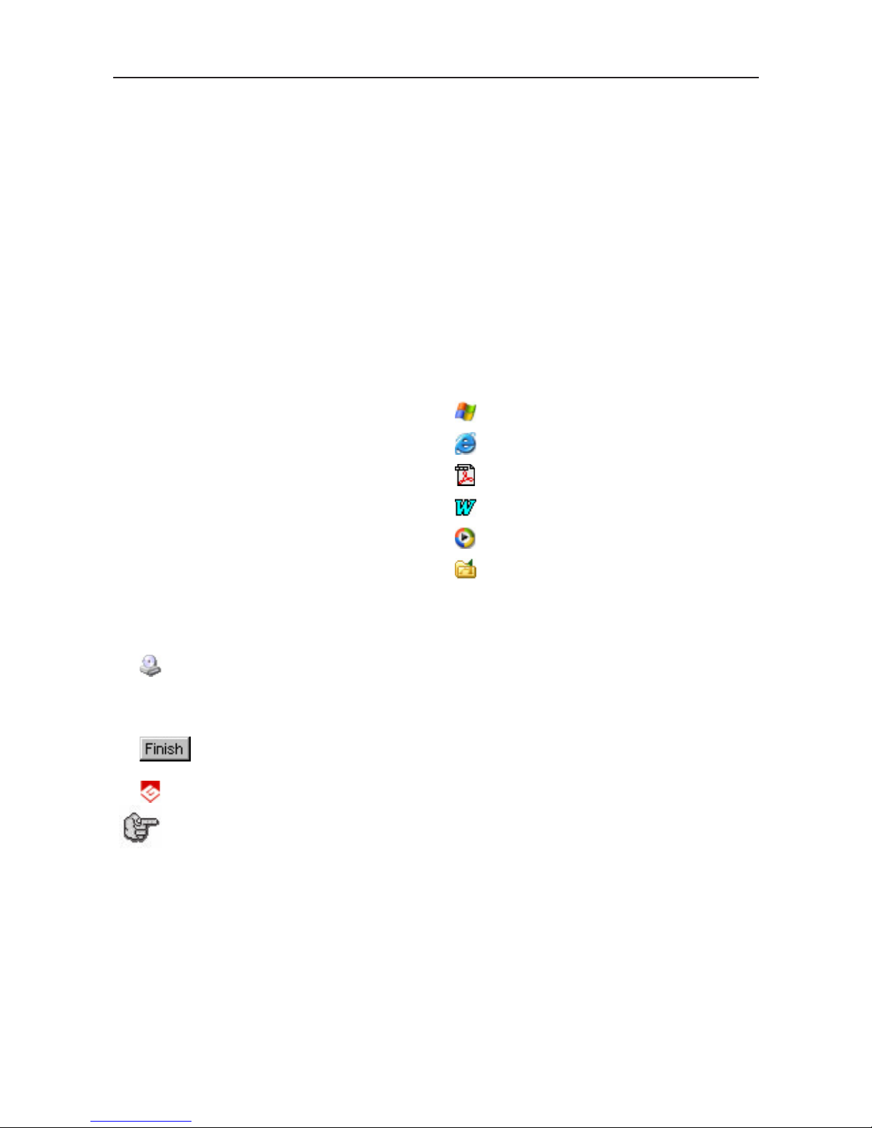
2. Insert the CD-ROM in the drive and close the drive.
3. Wait until the Installation screen is displayed.
Double-click the CD-ROM icon if the installation is not self-opening.
4. The installation automatically runs : the Progression bar and panel indicate the course of
operations.
5. Click to quit the Installation panel.
6. Run GravoStyle : Click its icon on the desktop.
Windows create automatically a virtual USB port as soon as the machine and the PC
computer are connected and switched on.
From your engraving software, install a "generic/text only" printer.
Then indicate from Windows (printer properties) the virtual USB port created previously
by Windows as the destination port of this "generic/text only" printer.
Page 24
IS400 machine . 24
First contact
Engraving
Positioning the plate onto the vice
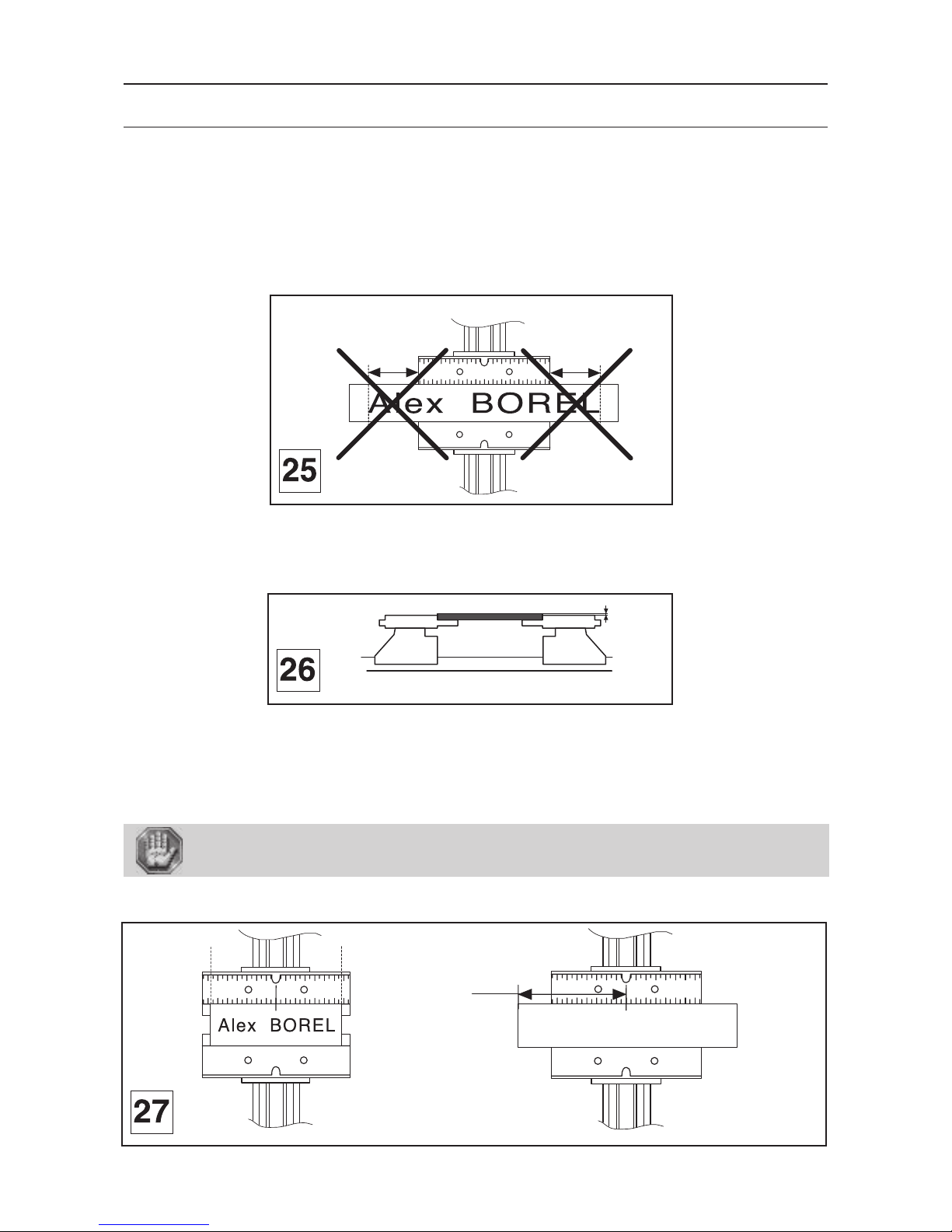
3. Choose the jigs according to the length of the plate (consult your GRAVOGRAPH dealer for more
information on the various jigs available).
The length of the plate should not exceed the length of the jigs (pict. 25).
See "Clamping the object to be engraved" in the "Physical configuration of the machine" paragraph of chapter "Engraving
techniques" in the user manual "CN 97 Program".
4. Choose adequate side of the jigs according to the thickness of the plate.
The plate should be slightly higher than the jigs (pict. 26) to avoid that the regulating nose touches the jigs.
5. Mark the middle of the plate.
6. Centre the plate so that the centre mark is lined up with the 0 on the jig (diagram 27).
7. Using the tightening knob, tighten the plate so that it cannot move during engraving.
If the plate is correctly tightened, noise and vibrations are reduced to a minimum when the machine is engraving.
Check that the object is tightened correctly to ensure that it is not ejected during
engraving.
7654
3
2
10
1
2
3
4
5
6
7
7654
3
2
10
1
2
3
4
5
6
7
Alex BOREL
100 mm
7654
3
2
10
1
2
3
4
5
6
7
Page 25
First contact
IS400 machine . 25
Point and Shoot
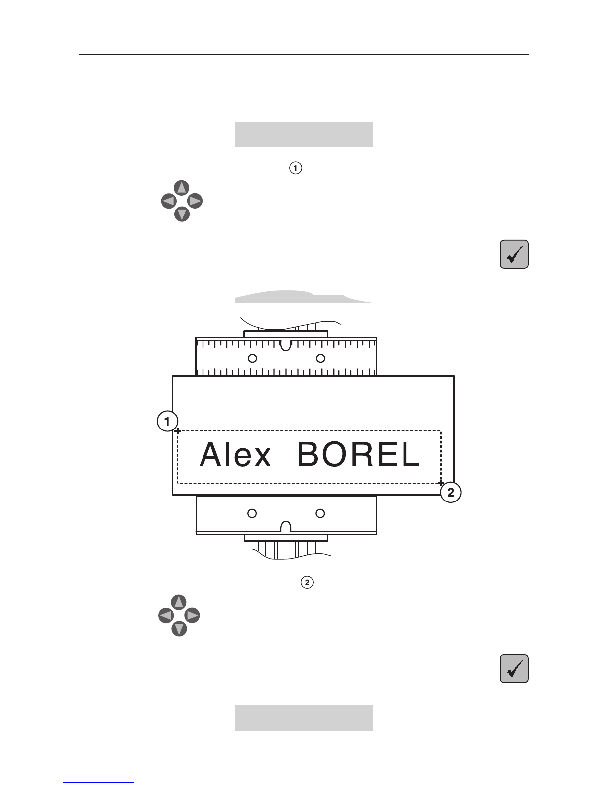
This GravoStyle function permits to define the engraving area on the plate with the machine.
7. Click on "Point and Shoot" in Gravostyle
This message is displayed on the LCD-screen of the control panel of the IS400:
<JOYSTICK>
X = xxx.xx I Y = xxx.xx
8. Move the spindle to the first corner (pict.) of the area to engrave by using the
joystick
9. Validate
<JOYSTICK>
X = xxx.xx I Y = xxx.xx
10. Move the spindle to the opposite corner (pict.) of the area to engrave by using the
joystick
11. Validate
This message is displayed on the LCD-screen :
<READY TO RECEIVE>
7654
3
2
10
1
2
3
4
5
6
7
Page 26

IS400 machine . 26
First contact
Transfer procedure
You have just created a composition with your engraving software.
1. From your engraving software, transfer the composition to the IS400 machine.
The engraving machine displays the number of bytes received :
To engrave
XXXX bytes received
The following message is displayed for a few seconds as soon as the transfer is complete :
TRANSFER COMPLETED
Then the following message is displayed :
<READY TO RECEIVE>
To engrave
The machine is ready to engrave.
Page 27
First contact
IS400 machine . 27
Adjusting the spindle
Setting up the spindle
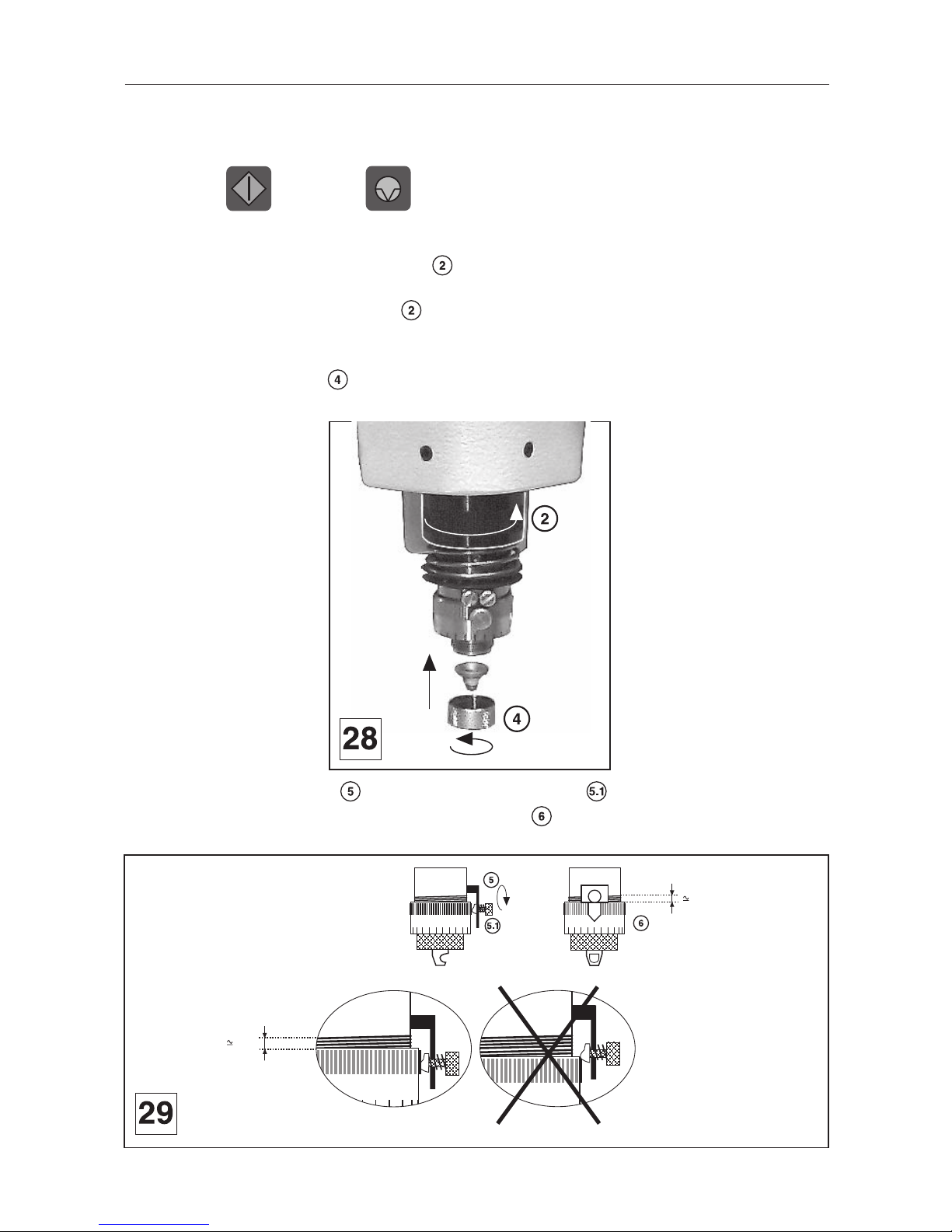
8. Press the key and the key straight after.
The tool holder stops above the material to be engraved exactly where the engraving should start.
9. Set the spindle pressure with the knob (the tightening direction is indicated by the arrow in
diagram 28).
To engrave without a nose, the pressure knob must be completely loosened so that the spindle is rigid.
To engrave with a nose, the setting depends on the hardness of the material, on the cutter width and on the surface state
of the plate selected (if the nose is likely to scratch the object, reduce the pressure).
10. Set the regulating nose in place on the spindle and tighten the nose nut.
11. Unscrew the index finger then unscrew the scaled knob (diagram 29).
Line up the 0 of the scaled knob with the index finger . The scaled knob should be unscrewed
in such a way that the index finger blocks it.
5
5
0
2 mm
2 mm
Page 28
IS400 machine . 28
First contact
Putting the cutter into the spindle
This plate will be engraved using a conical tool (or conical cutter) made of high speed steel with a 4.36 mm diameter and
a 0.50 tip.
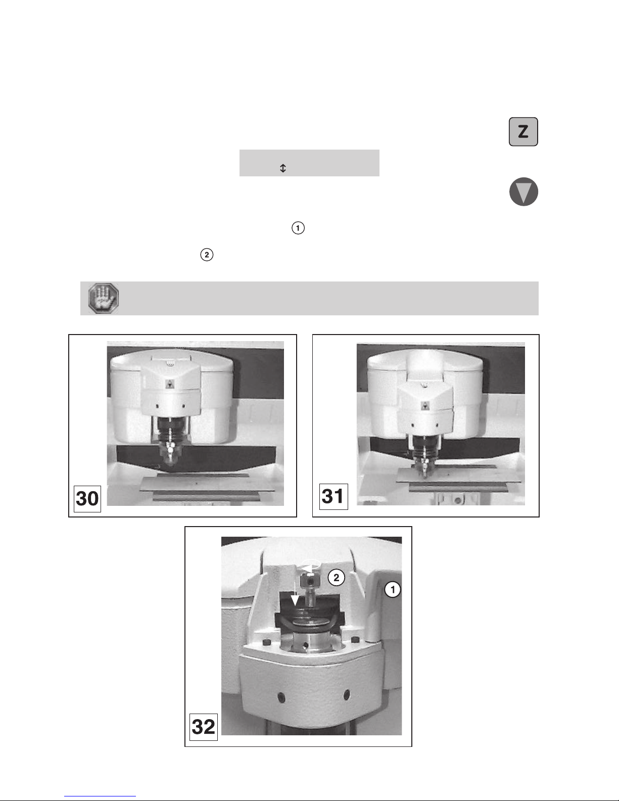
12. Lower the spindle until the depth regulating nose touches the material to be engraved
(diagram 31).
Press
ZREF = 0.00 mm
to change
To lower press
13. Open the belt housing of the tool-holder (diagram 32).
14. Screw knob of cutter onto the spindle (diagram 32).
The spindle knob should be tightened anti-clockwise (knob with left-hand thread).
The tool is very sharp and to avoid any risks of getting cut, you are advised to use some
kind of protection (gloves) to handle it.
Page 29
First contact
IS400 machine . 29
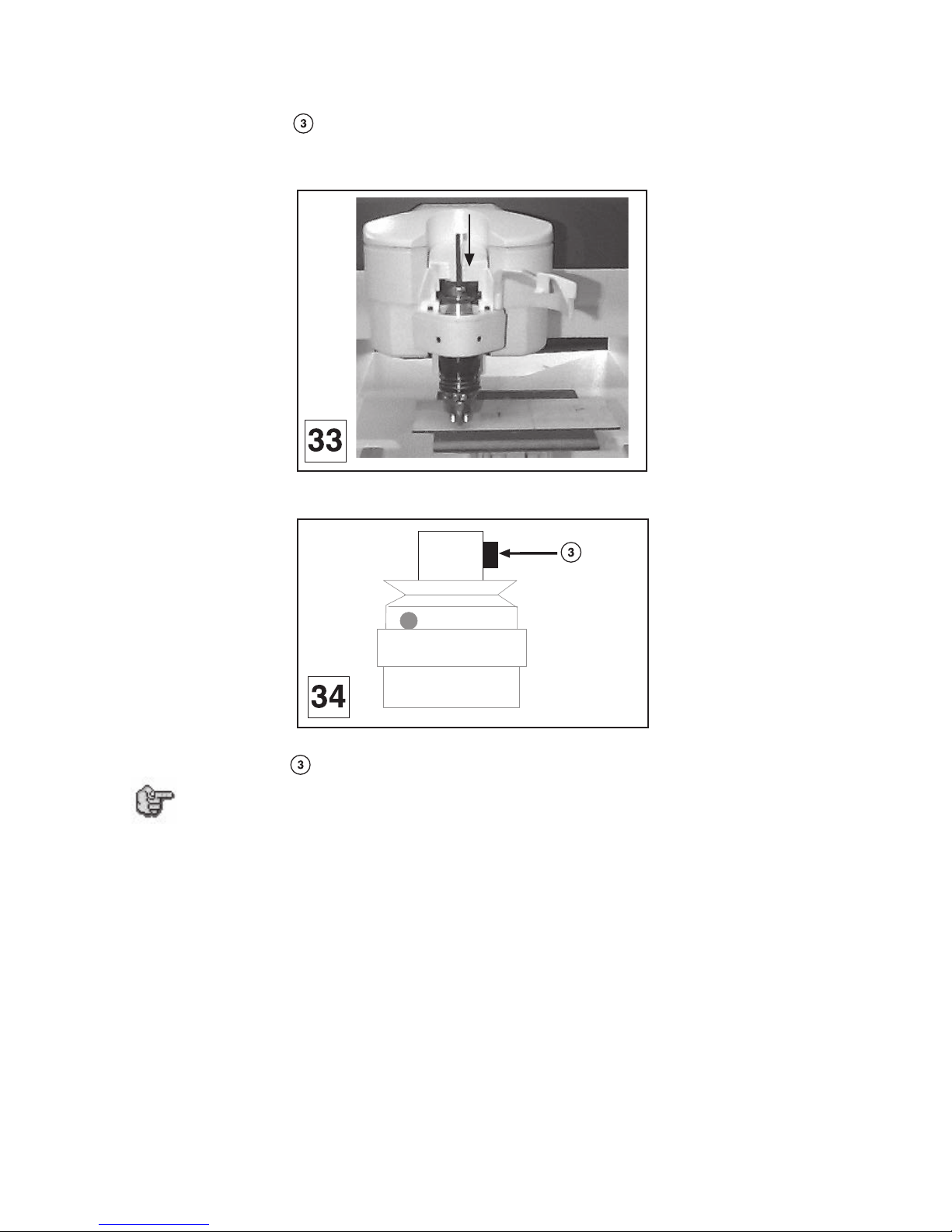
15. Insert the cutter into the button until it is touching slightly (carbide cutters are not very shock
resistant) the engraving material (diagram 33). To facilitate the insertion of the cutter, slightly
unscrew the screw located on the spindle knob (diagram 34).
Remember to program 0.5 to 1 mm depth to compensate possible flatness faults of the plate.
16. Tighten the screw of the cutter button to lock it into place.
For greater convenience, we advise that you have as many cutter knobs as you have
cutters, so you can leave them together and keep the settings for possible jobs to be
carried out in the same conditions in the future (same thickness of materials).
For this, you will need to request "the machine configuration save with ZREF" (see
"Saving the machine configuration" paragraph of chapter "Basic techniques" in the
user manual "CN97 Program").
Page 30
IS400 machine . 30
First contact
Setting-up the spindle origin
17. Save the position of the spindle by pressing
The spindle moves up.
Adjusting the tool depth
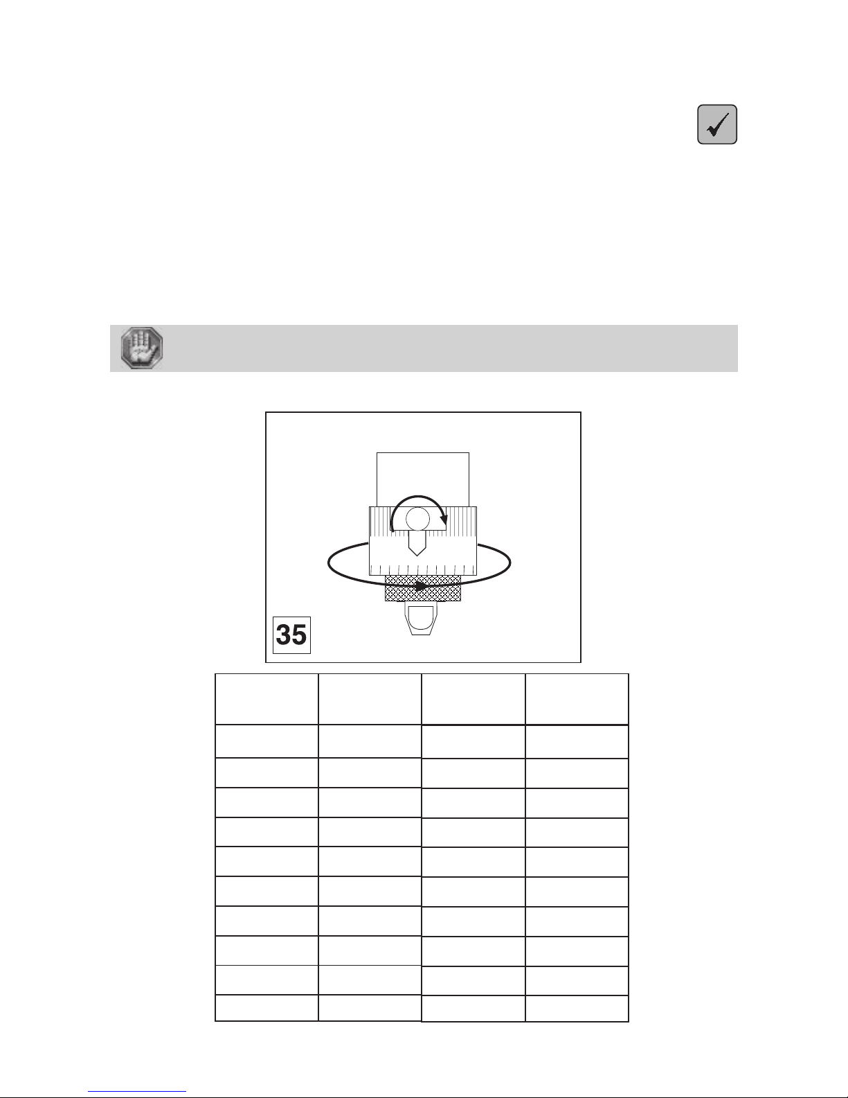
18. Turn the index finger a few notches to the right to obtain the desired engraving depth (one notch
= 0.025 mm) (diagram 35).
Refer to the table opposite for the number of marks to move the index finger depending on the desired depth and the material
used.
19. Tighten the index finger in order to maintain the scaled knob in this position.
20. Close the belt housing of the tool-holder.
To avoid any risks of getting burnt, the protective belt housing of the tool-holder must
be always closed, except when carrying out adjustments.
05
Anodisal
Silver
Chrome
Gravometal
Gravoply II
Stainless Steel
Brass
Metallex
Gold
Plastic
Engraving
material
Carbide
Carbide
Diamond
Carbide
Carbide
Diamond
Carbide
Carbide
Carbide
Carbide
Type of cutter
0,1
0,3
0,025
0,1
0,1
0,2
0,2
0,1
0,3
0,2
Engraving depth
in mm
4
12
1
4
4
8
8
4
12
8
Number of
marks
Page 31
First contact
IS400 machine . 31
Adjusting the rotation speed on the spindle
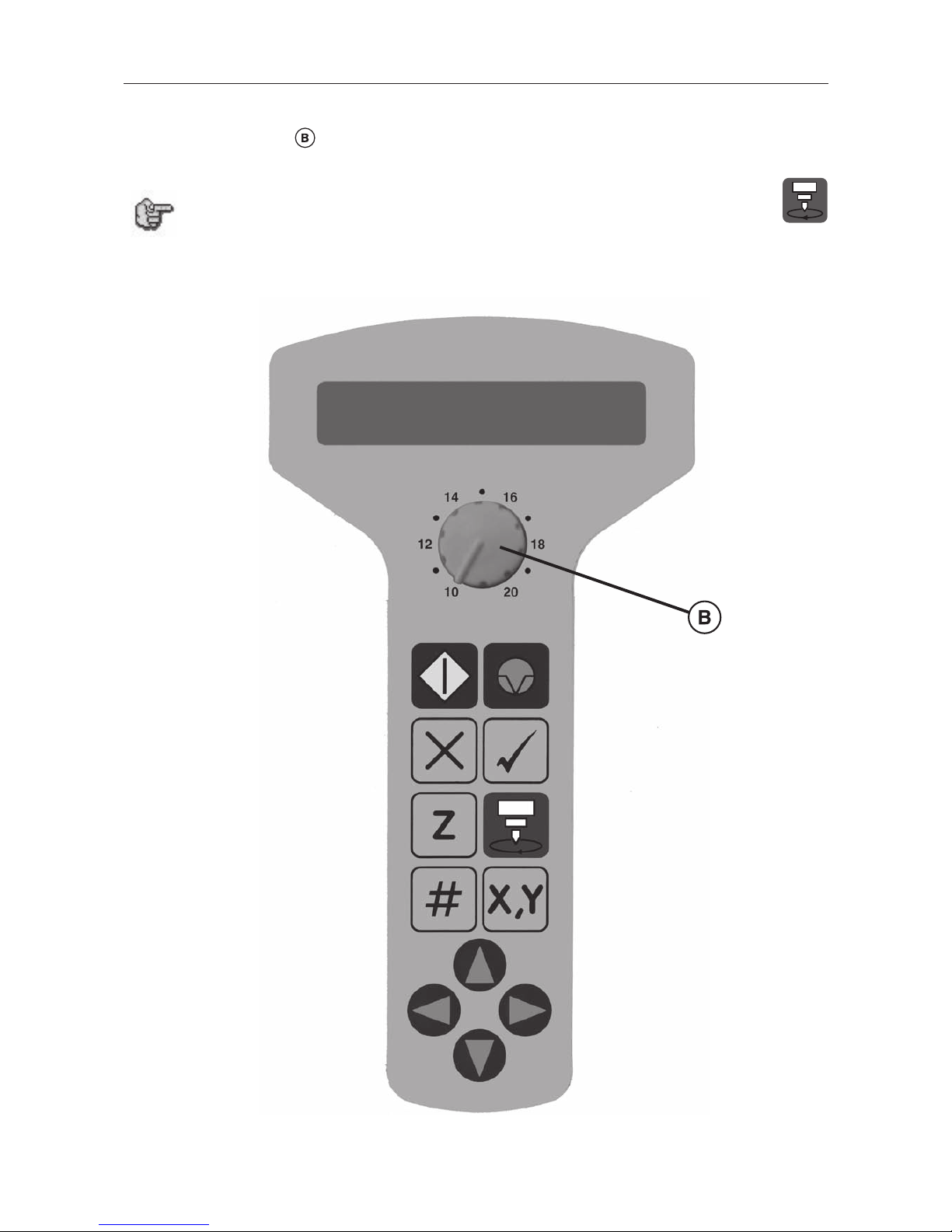
21. Turn the button on the control panel to the speed required (from 10000 to
20000 rpm)
If you wish the spindle to remain without rotation press
Page 32
IS400 machine . 32
First contact
Starting to engrave
This sign shown on the spindle of the machine shows the danger caused by the
rotating spindle during engraving (risks of getting burnt or cut).
To avoid any risks of getting burnt, the belt housing of the tool-holder must be always
closed except for when adjusting the tool-holder and changing the spindle belt.
For your own personal safety and to avoid any risks of being crushed by the machine
during engraving, do not stand near the tools or lean over the spindle holder (the travel
area of the tool is 305 x 210mm).
Always wear protective glasses againts chip ejection.
Before starting the engraving, ensure that the spindle travel area is completely clear.
Ensure that no one is in the travelling area of the moving parts of the machine and that
no object will obstruct the travelling of the moving parts.
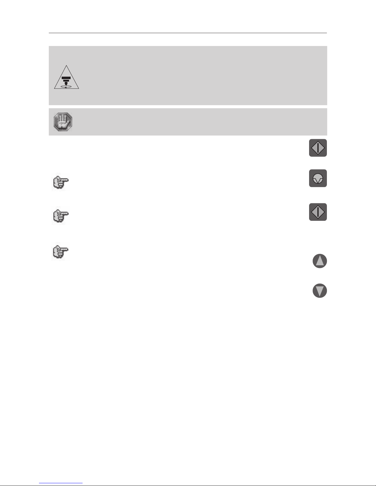
22. Press START (Engraving Start)
The tool holder moves over to the first point on the engraving and starts to engrave.
To stop engraving (if there is a problem), press PAUSE
The machine will pause.
To continue engraving, press START (Engraving Start)
To stop engraving completely, press one of the arrows on the joystick.
To increase the travel speed of the spindle during engraving,
press the arrow
To reduce the travel speed of the spindle during engraving,
press the arrow
Page 33
First contact
IS400 machine . 33
General maintenance
Before carrying out any maintenance, unplug the mains supply cable.
No internal part of the Gravograph machine requires user intervention : general maintenance is limited to external cleaning.
If necessary, the user can change the belt.
If you wish to have the inside of your machine cleaned, contact a Gravograph technician.
The mains cable should always be replaced if it is damaged in any way : flattened,
nicked, cracked etc..., or if there are bare wires.
Changing the belt
You will find a spare belt in the machine tool box.
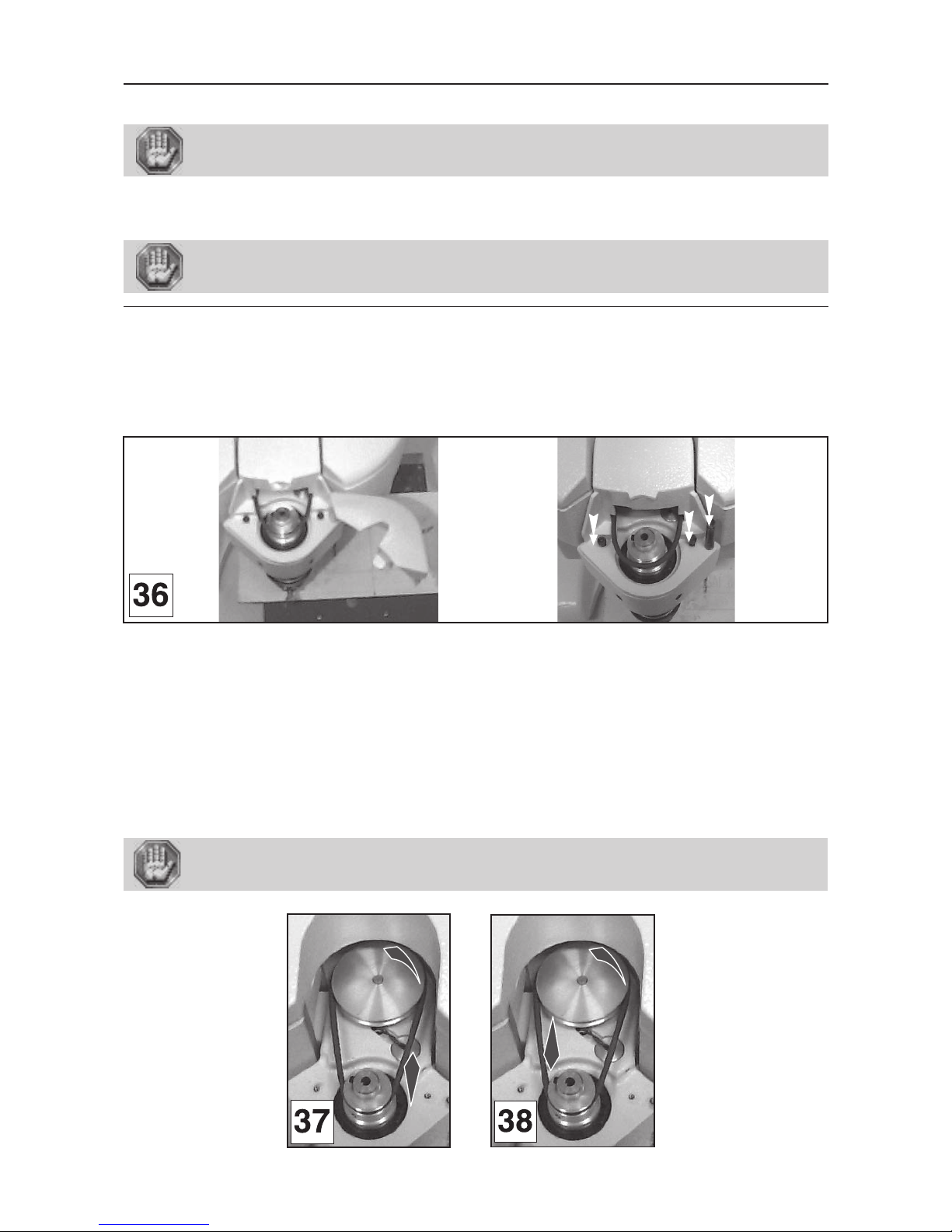
1. Open the protective housing of the tool-holder and take it out by lifting it upwards (diagram 36).
2. Loosen the 2 screws fixing the belt housing and the axis of the protective housing of the tool-
holder, then take of the belt housing (pict 36).
3. Pull the belt off with one hand, and turn the motor pulley with the other (pict 37).
4. Put the belt in the spindle pulley groove.
5. Put the belt into the pulley groove opening with one hand and turn the pulley with the other
(pict 38).
6. Replace the plastic casing and tighten the two screws fixing the case.
7. Screw the axis of the tool-holder housing and replace it.
8. Close the tool-holder housing.
To avoid any risks of getting burnt, the protective belt housing of the tool-holder must
be always closed, except when carrying out adjustments.
Page 34
IS400 machine . 34
First contact
Adjusting the machine
After it has been used for some while the reference point of the machine can alter slightly (the centre of the engraving area
of the machine is slightly out of line with the clamping system, the Z position at the mechanical stop is above or below its
normal position).
The IS400 machine has a very simple adjustment system which can be carried out by the user (which enables the machine
to be adjusted without having to return it to the distributor).
If you notice that it is out of line in relation to your engraving measurements, adjust the machine.
To adjust the machine
1. Switch on the IS400 machine.
<<GRAVOGRAPH>>
- VERSION xx.xx -
2. When this message is displayed press
SPINDLE ORIG. ADJUST
to confirm
3. Take off the jigs
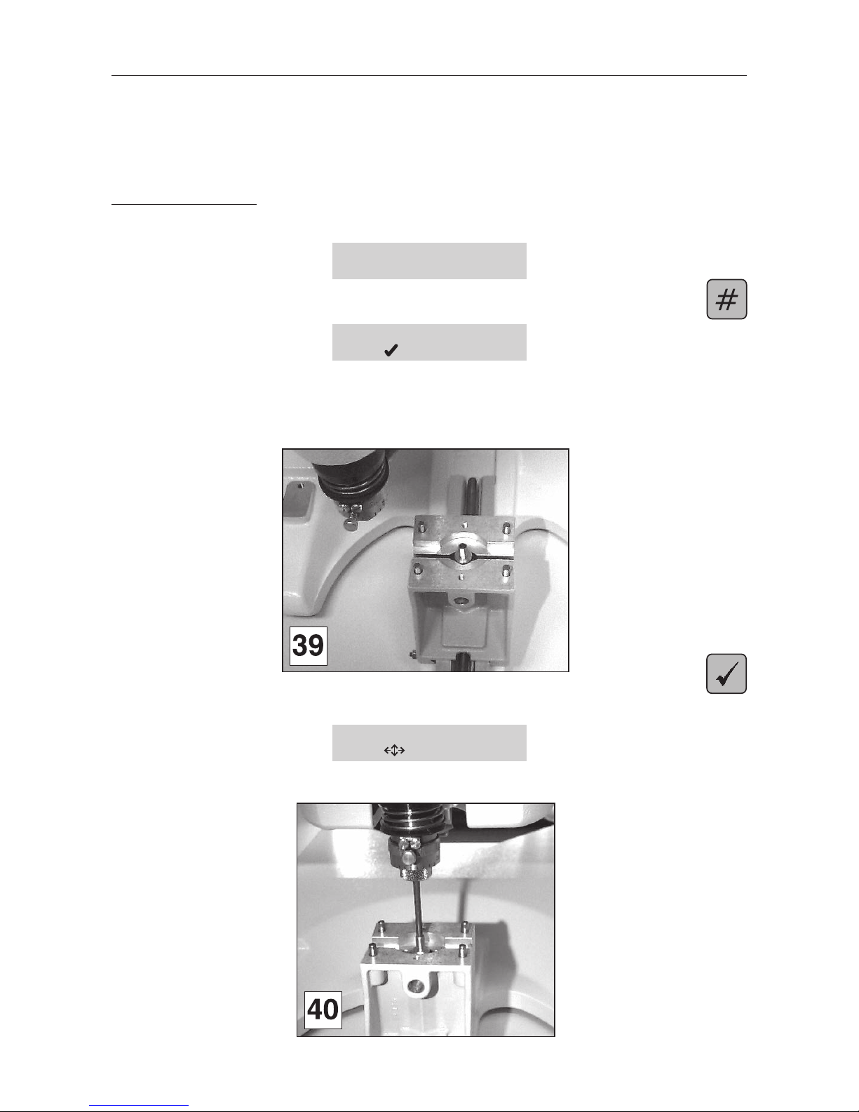
4. Put the cutter button between the jaws of the vice and tighten using the tightening button
(diagram 39).
5. Validate
The tool-holder moves towards the centre of the vice (diagram 40).
SPINDLE ORIG. ADJUST
to modify
6. Place the cutter into the spindle (diagram 40). It should easily slide into the cutter button.
Page 35
First contact
IS400 machine . 35
7. If it does not, take the cutter out, adjust the position of the tool-holder using the joystick, and
put the cutter in again.
8. Repeat steps 6 and 7 until the cutter easily slides in.
9. Once it is correctly adjusted, take the cutter out of the spindle.
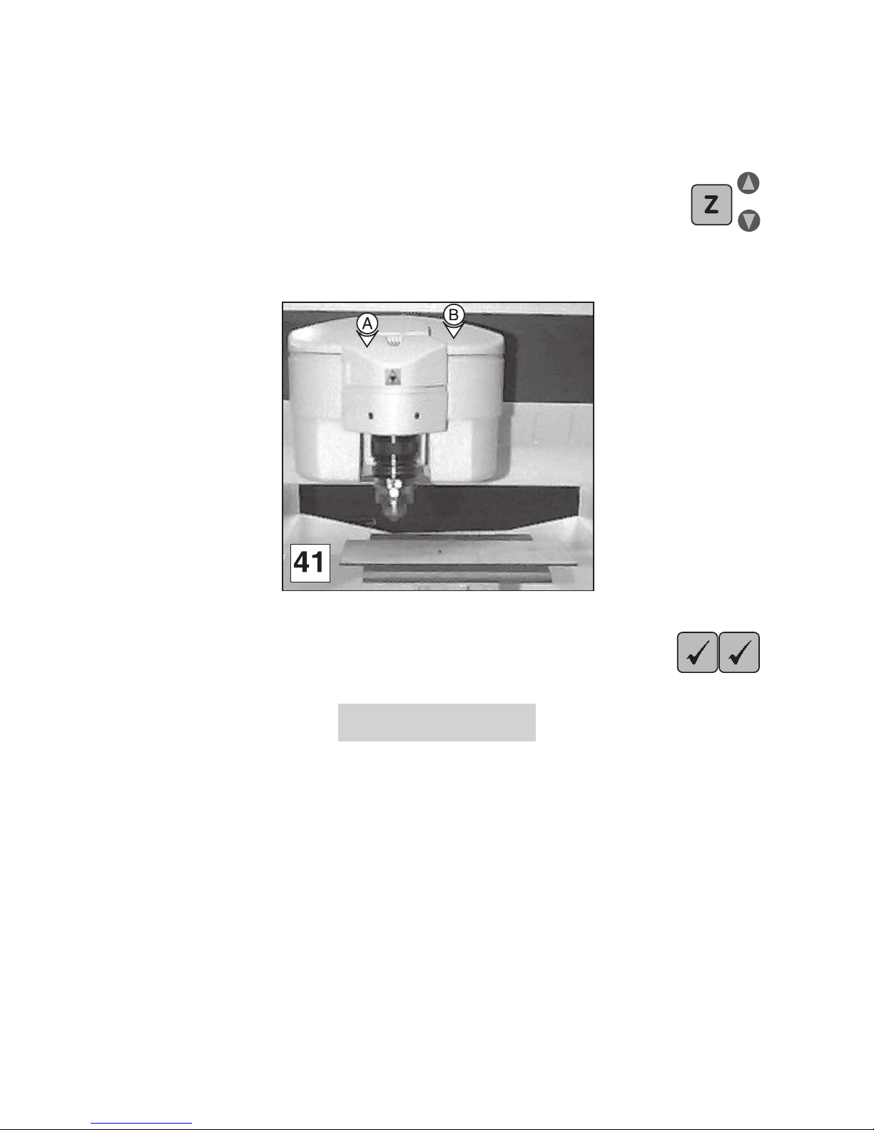
10. Adjust the position of the Z mechanical stop.
Adjust the Z position so that surface (A) and surface (B) are aligned (diagram 41).
11. Set the adjustment. Validate twice.
The machine adjustment is recorded by the machine.
SAVE CONFIGURATION
Saving ...
Page 36

IS400 machine . 36
First contact
Technical Characteristics
Mechanical Characteristics
Machine
Size mm 435 x 610 x 893
Net weight kg 42
Max. engraving area mm 305 x 210
Packaging
Overall size mm 1020 x 750 x 670
Weight (packaging + machine) kg 68
Vice
Max. length mm unlimited x 230
Maximum object weight kg 20
Max. opening mm 230
Height of jaws mm 75
Spindle and jig clearance mm 33
Standard spindle
Tool
Type Rotating, top-loading
Diameter mm 4.36
inches 11/64
Max. rotation speed tr/min. 20000
Spindle displacement speed
Off-load travelling speed mm/s 60
Working speed up to mm/s 35
Spindle travel
in Z direction mm 40
Max. precision
X mm 0.0127
Y mm 0.0127
Z mm 0.0127
Levelness
X mm 0.2
Y mm 0.2
Control panel
Number of keys 12
Type Membrane with raised tactile points
Display LCD 2 lines of 20 characters
Page 37

First contact
IS400 machine . 37
Sound signal according to standard ISO 11201
off-load* LAeq db(A) < 72 ± 1
nominal engraving* LAeq db(A) 80 ± 2
nominal engraving peak* Lp Cpeak db(C) < 95
Environment *according to norm EN60721
Operational temperature* - Min. ° C+5
- Max. ° C +40
Storage temperature * - Mini. ° C-5
- Maxi ° C +45
Degree of moisture when in use % 5 to 85
Point & Shoot
Kind LASER diode
Wavelength 630-680 nm
Max. output / Class 1 mW / Class 2
Electrical Characteristics
Machine
Power supply V 100 - 240
Max. absorbed current A 3.5
Frequency Hz 50 - 60
Output W 300
Insulation Classe 1
Type of service S1
Electromagnetic compatibility Emission : norm EN 50081-1 (residential environment)
Immunity : norm EN 61000-6-2 (industrial environment)
Type of protection Fuse 5 x 20 mm 4A F1T
Degree of protection IP40
Spindle motor
Type Continuous current
Output W 70
Absorbed current A 2.5
Speed tr/min. 3700-7500
Displacement motor
Stepper motor step/revs 200
Connexions - Liaisons
Parallel
USB 1.1 or 2.0
Memory card 38 points
Engraving software characteristics
GravoStyle
Operating system Windows 2000 / Windows XP
Page 38

IS400 machine . 38
First contact
Optional accessories
Pen attachment D2524 000
Reference (user manual) D2136 799
Weight Kg 1.150
Ext. dimensions mm 270 x 135 x 74
Maximum object weight kg 0.3
Min.-max. diameter mm 5 - 15
Max. length mm 160
Cylinder attachment D2521 000
Reference (user manual) D2135 799
Weight Kg 4.7
Ext. dimensions mm 450 x 220 x 150
Maximum object weight kg
Min.-max. diameter mm - 110
Max. length mm 200
Vacuum table
Reference (user manual)
Ext. dimensions mm 353 x 360 x 30
Max. extraction surface mm 310 x 210
Max. engraving area mm 305 x 210
Spindle clearance mm 25
T-slot table D2502 000
Reference (user manual) D2097 799
Ext. dimensions mm 314 x 404 x 85
Max. engraving area mm 305 x 210
Spindle clearance mm 30
Spindles
Collet B2701 000
Diamond A0140 100
Rotring A0274 000
High frequency Not available
Pyroengraver A0270 100
 Loading...