

Page 1
GSA VESA 1
35 MM POLE MOUNT LCD TV MONITOR BRACKET
WITH 7 VESA HOLE PATTERNS
SAFETY INFORMATION
1. Please read these instructions carefully before you start installation
and assembly.
2. Keep all information and instructions in a safe place.
3. Follow the instructions.
4. Observe all safety warnings. Never remove safety warnings or
other
information from the equipment.
5. Be attentive when setting up the product and protect yourself
from injury.
6. This product is intended for indoor use only. Using it outdoors
could lead to product failure and personal injury.
7. Do not modify this equipment.
8. Comply with all applicable disposal laws in your country. During
disposal of packaging, please separate plastic and paper/
cardboard.
9. Plastic bags must be kept out of reach of children.
10. If you have any questions refering to this instruction or any
warnings, please contact your local distributor.
IMPORTANT INFORMATION AND SAFETY INSTRUCTIONS
SPECIFIC TO THE PRODUCT
Mounting a monitor on the monitor bracket requires su
cient experience in handling technical devices and tools.
In case of doubt, do not carry out the installation alone;
obtain assistance from an experienced technician.
-
1. The screws, with which the monitor is attached to the bracket,
must comply with specifications for diameter, length, and threading
in order to avoid damaging the monitor and prevent the monitor
from falling. If the screws provided do not meet these requirements,
suitable screws, which can be obtained from specialists, must be
used (use suitable washers as necessary). If the screws are too long
or if the threading does not comply with the threading of the monitor, the monitor may be damaged. If the screws are too short, the
monitor will not be attached with sufficient strength and may fall.
The screws must be screwed into the corresponding threads of the
monitor for at least 5 full rotations.
2. Follow all instructions in the device operating instructions provid
-
ed by the monitor manufacturer with respect to bracket mounting.
3. When screwing tight, do not use excessive force in order to avoid
damaging the monitor.
4. Inspect the screw connections at regular intervals.
5. Use only suitable stands with 35 mm pipe ends and a load ca
-
pacity suitable for the monitor plus bracket.
6. If instructions are not followed, there is a risk of injury and device
damage during installation and use of the bracket.
7. Use the monitor, bracket, and stand only for their intended pur
-
pose.
8. The manufacturer is not liable for damage caused by improper
installation and use.
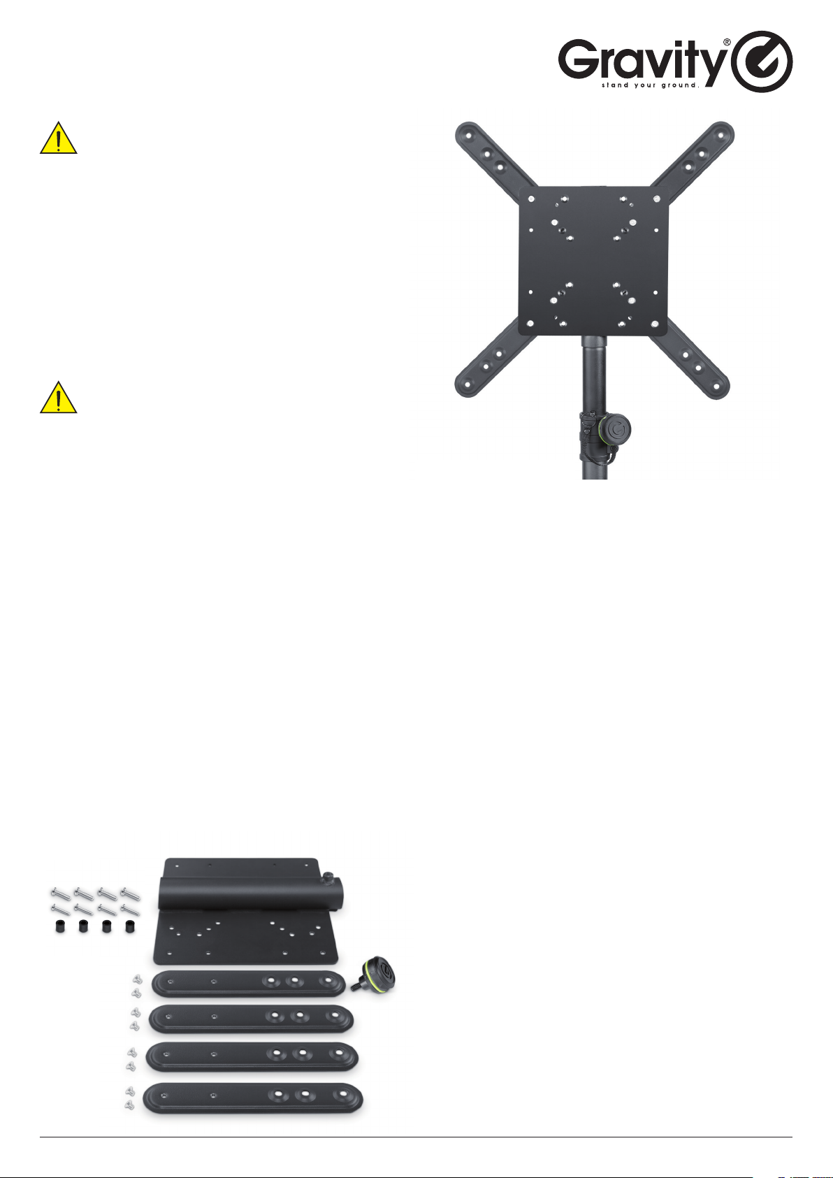
9. Verify that the scope of delivery is complete before installation.
SCOPE OF DELIVERY
Stand not included in delivery
FEATURES
• Quickly and securely mounts monitors to 35 mm speaker poles
• For all flat screens with VESA hole patterns
from 75 x 75 to 400 x 400
• Durable heavy duty construction
• Maximum load capacity 30 kg
• Includes M8 and M6 monitor mounting screws
DESCRIPTION
This universal bracket is suitable for all flat screen monitors with
VESA standard mounting hole patterns from 75 x 75 to 400 x 400
and securely clamps to 35 mm speaker poles. The heavy duty steel
construction with black powder coating finish has a maximum load
capacity of 30 kg and comes complete with sets of M8 and M6
monitor mounting screws.
INSTALLATION
1. Disconnect the monitor from any power source (pull out plug)
and remove all connection cables before installation.
2. Carefully place the monitor with display on a flat surface of
sufficient size and ensure that the display and frame cannot be
damaged (with the help of a second person, as needed). Remove
the pedestal from the monitor (see manufacturer operating instruc
-
tions), as necessary.
3A. For the VESA dimensions of 75 x 75, 100 x 100, 200 x 100, and 200
x 200, now place the base plate (without lengthening elements),
with the flat side and flange opening facing downwards, on the
monitor’s rear side in such a way that the screw holes in the base
plate align with the screw threads in the monitor.
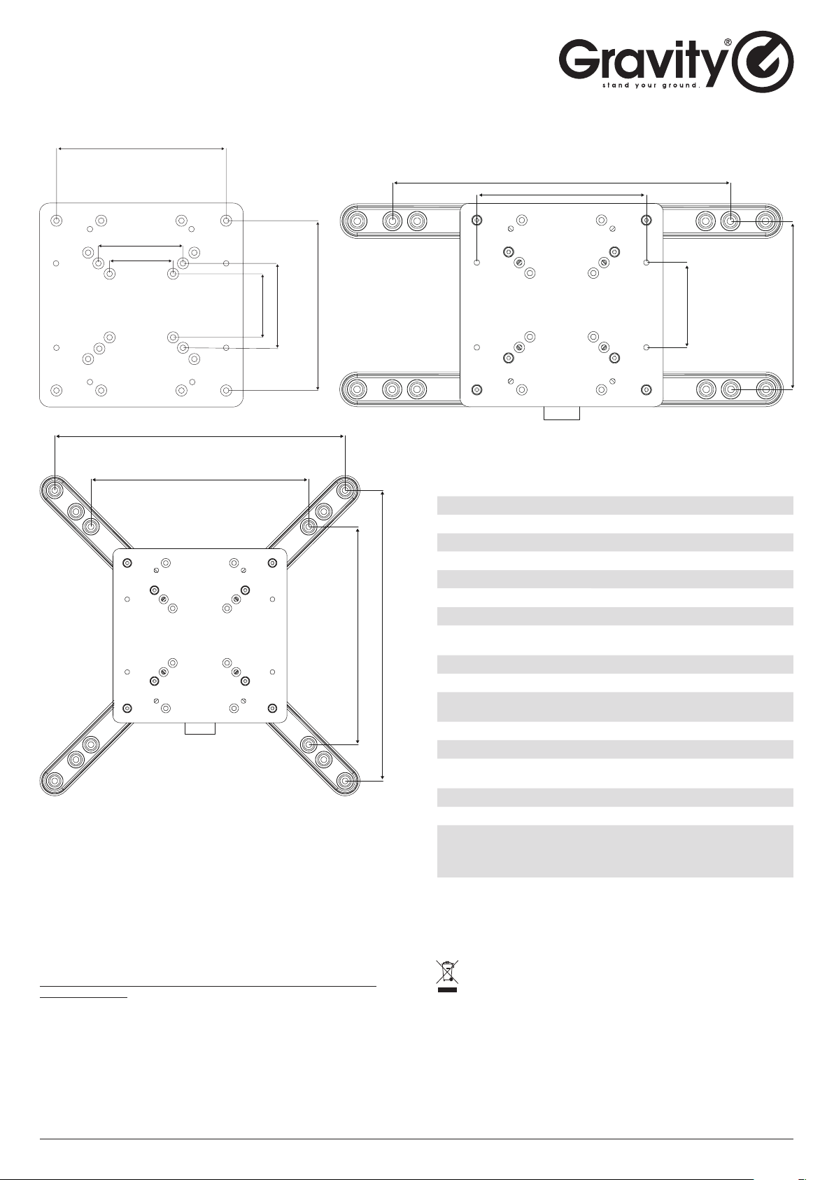
3B. For the VESA dimensions of 300 x 300, 400 x 200, and 400 x 400,
first attach the lengthening elements, with the bulge facing the
monitor, in their corresponding positions on the rear side of the base
plate using the provided M6 countersunk screws (ensure that there
is sufficient hold!). Please consult the corresponding drawings in
these instructions for the correct positions. Now lay the base plate
with lengthening elements, with the flat side and flange opening
facing downwards, on the monitor’s rear side in such a way that
the screw holes in the lengthening elements align with the screw
threads in the monitor. If the monitor has a convex rear side, please
also use the provided spacers in order to attach the bracket to the
monitor.
4. Screw down the monitor bracket to the monitor using suitable
screws. When doing so, always follow what is given under IMPORT
ANT INFORMATION AND SAFETY INSTRUCTIONS SPECIFIC TO THE
PRODUCT in these operating instructions.
5. Now lift the monitor with bracket onto a suitable stand (e.g box
stand) and provided thumb screws.
Adam Hall GmbH · Adam-Hall-Str. 1· 61267 Neu-Anspach · Germany
Tel.: (+49) 60 81 / 94 19 0 · Fax: (+49) 60 81 / 94 19 1000 · eMail: [email protected]
Page 2
GSA VESA 1
35 MM POLE MOUNT LCD TV MONITOR BRACKET
WITH 7 VESA HOLE PATTERNS
200
100
75
400
200
400
300
75 100 200
300
400
100 200
SPECIFICATIONS
Product type Stands and Tripod Accessories
Type Universal Monitor mount
Material Steel
Surface Powder coated
Colour Black
Suitable for tube diameter 35 mm
Max. load 30 kg
Suitable for VESA dimensions 200 x 200, 400 x 400, 100 x 100, 200 x 100,
Length base plate (mm) 240
Width base plate (mm) 240
Material thickness base plate
(mm)
Length extensions (mm) 240
Width extensions (mm) 45
Material thickness extensions
(mm)
Interchangeable rings 1 x 25 mm
Black ring pack included Yes
Accessories (included) 4 x extensions, 4 x M6 screws, 4x dis-
Weight 2.71 kg
300 x 300, 400 x 200, 75 x 75
3
2
tance holders, Base plate with 35 mm
pole mount and locking screw, 4 x M8
screws, 8x M6 countersunk screws
MANUFACTURER’S WARRANTY & LIMITATION OF LIABILITY
You can find our current warranty conditions and limitation of liability at:
https://cdn-shop.adamhall.com/media/pdf/MANUFACTURERS-DECLARATIONS_GRAVITY.pdf
To request warranty service for a product, please contact Adam Hall GmbH,
Adam-Hall-Str. 1, 61267 Neu Anspach / Email [email protected] /
49 (0) 6081 / 9419-0
Adam Hall GmbH · Adam-Hall-Str. 1· 61267 Neu-Anspach · Germany
Tel.: (+49) 60 81 / 94 19 0 · Fax: (+49) 60 81 / 94 19 1000 · eMail: [email protected]
PROPER DISPOSAL OF THIS PRODUCT
(WASTE ELECTRICAL AND ELECTRONIC EQUIPMENT)
(Valid in the European Union and other European countries with waste
separation)
This symbol on the product, or the documents accompanying the product,
indicates that this appliance may not be treated as household waste. This is
to avoid environmental damage or personal injury due to uncontrolled waste
disposal. Please dispose of this product separately from other waste and
have it recycled to promote sustainable economic activity.
Page 3
GSA VESA 1
VESAADAPTER ZUR BILDSCHIRMMONTAGE
AN 35 MM STATIVROHREN
SICHERHEITSHINWEISE
1. Bitte lesen Sie diese Bedienungsanleitung sorgfältig, bevor Sie
mit der Montage und dem Aufbau beginnen.
2. Bewahren Sie alle Informationen und Anleitungen an einem
sicheren Ort auf.
3. Folgen Sie den Anleitungen.
4. Beachten Sie stets alle Sicherheitshinweise. Entfernen Sie
niemals Sicherheitshinweise oder andere Informationen von
dem Produkt.
5. Seien Sie beim Aufbauen des Produkts aufmerksam und
schützen sich vor Verletzungen.
6. Dieses Produkt ist ausschließlich für den Einsatz in Innen
räumen bestimmt. Der Einsatz im Außenbereich kann zu
Schäden am Produkt und zu Personenschäden führen.
7. Nehmen Sie keine Veränderungen an diesem Produkt vor.
8. Beachten Sie bei der Entsorgung die in Ihrem Land geltenden
Gesetze. Trennen Sie bei der Entsorgung bitte Kunststoff und
Papier bzw. Kartonagen voneinander.
9. Kunststoffbeutel müssen außer Reichweite von Kindern aufbe
wahrt werden.
10. Falls Sie Fragen zu dieser Anleitung oder zu den Sicherheit
shinweisen haben, wenden Sie sich bitte an Ihren Fachhändler/Vertrieb.
WICHTIGE INFORMATIONEN UND SICHERHEITSHINWEISE
SPEZIFISCH ZUM PRODUKT
Die Montage eines Monitors an der Monitorhalterung erfordert
ausreichende Erfahrung im Umgang mit technischen Geräten
und Werkzeug. Führen Sie die Montage im Zweifelsfall nicht
selbst durch, sondern nutzen Sie die Hilfe einer erfahrenen
Fachkra.
1. Die Schrauben, mit denen der Monitor an der Halterung befestigt wird,
müssen in Durchmesser, Länge und Gewindesteigung den Monitorspezi
kationen entsprechen, um den Monitor nicht zu beschädigen und das
Herabfallen des Monitors zu verhindern. Falls die beiliegenden Schrauben
diese Anforderungen nicht erfüllen, müssen geeignete, im Fachhandel er
hältliche Schrauben verwendet werden (ggf. geeignete Unterlegscheiben
verwenden). Sind die Schrauben zu lang oder die Gewindesteigung nicht
der des Gewindes im Monitor entsprechend, kann der Monitor beschädigt
werden. Sind die Schrauben zu kurz, ist eine ausreichende Festigkeit der
Verbindung nicht gewährleistet und der Monitor kann herabfallen. Die
Schrauben müssen mindestens 5 volle Umdrehungen in die entsprechen
den Gewinde des Monitors eingeschraubt werden.
2. Beachten Sie alle Anweisungen, die der Monitorhersteller bezüglich der
Montage an einer Halterung in der Bedienungsanleitung des Geräts gibt.
3. Verwenden Sie beim Festschrauben nicht zu viel Gewalt, um den Monitor
nicht zu beschädigen.
4. Überprüfen Sie die Schraubverbindungen in regelmäßigen Abständen.
5. Verwenden Sie nur geeignete Stative mit 35mm Rohrende und mit einer
für Monitor plus Halterung ausreichenden Tragkra.
6. Werden Hinweise und Anweisungen nicht beachtet, bestehen bei der
Montage und der Nutzung der Halterung Verletzungsgefahr und die Ge
fahr von Geräteschäden.
7. Verwenden Sie Monitor, Halterung und Stativ nur für die dafür vorgeseh
enen Zwecke.
8. Der Hersteller haet nicht für Schäden, die durch unsachgemäße Mon
tage und Nutzung entstehen.
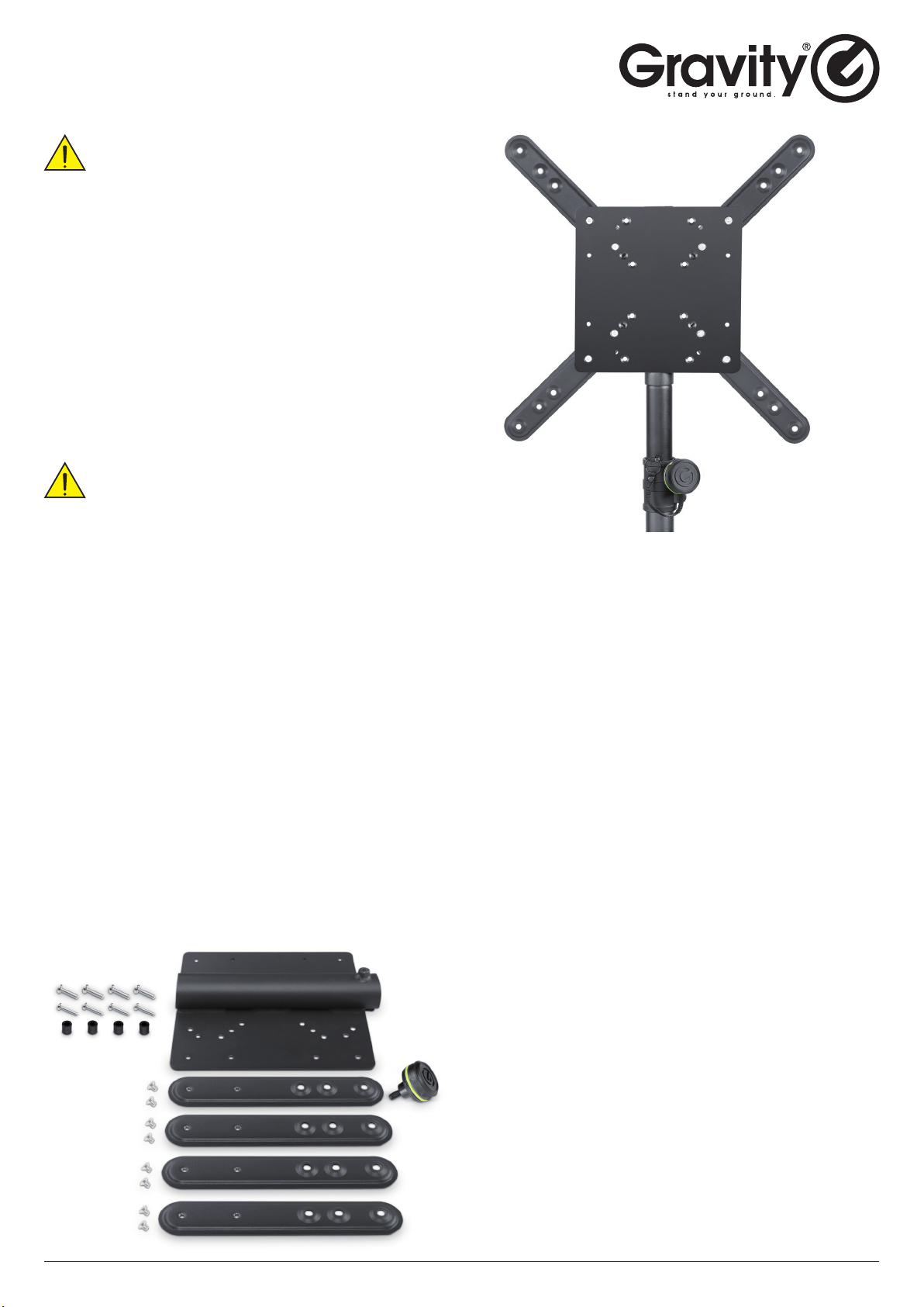
9. Überprüfen Sie vor der Montage den Lieferumfang auf Vollständigkeit.
LIEFERUMFANG
-
-
-
-
-
-
-
-
-
Stativ nicht im Lieferumfang
FEATURES
• Schnelle und stabile Monitor-Montage an 35 mm Stativrohren
• Für alle Flachbildschirme mit VESA-Lochabständen
von 75 x 75 bis 400 x 400
• Solide und langlebige Konstruktion
• Maximale Tragfähigkeit 30 kg
• Inkl. M8 und M6 Schrauben zur Monitor-Befestigung
BESCHREIBUNG
Diese Universal-Monitorhalterung lässt sich stabil an jedem 35 mm
Stativrohr anklemmen und eignet sich für alle Flachbildschirme mit
VESA-Lochmustern von 75 x 75 bis 400 x 400. Die robuste Konstruk
tion aus Stahl mit schwarzer Pulverbeschichtung hat eine maximale
Tragfähigkeit von 30 kg und wird mit M8- und M6-Schraubensätzen
zur Monitor-Befestigung geliefert.
MONTAGE
1. Trennen Sie den Monitor vor der Montage vom Stromnetz (Netzstecker ziehen) und entfernen alle Anschlusskabel.
2. Legen Sie den Monitor vorsichtig mit dem Display voran auf eine
ebene Fläche von ausreichender Größe und achten dabei darauf,
dass Display und Rahmen nicht beschädigt werden können (ggf.
mit Hilfe einer zweiten Person). Entfernen Sie ggf. den Standfuß vom
Monitor (siehe Bedienungsanleitung des Monitorherstellers).
3A. Bei den VESA-Maßen 75 x 75, 100 x 100, 200 x 100 und 200 x 200
legen Sie nun die Basisplatte (ohne Erweiterungselemente) mit der
flachen Seite und der Flanschöffnung nach unten zeigend auf die
Monitorrückseite, in der Art, dass die Schraublöcher in der Basis
-
platte und die Gewinde im Monitor übereinander liegen.
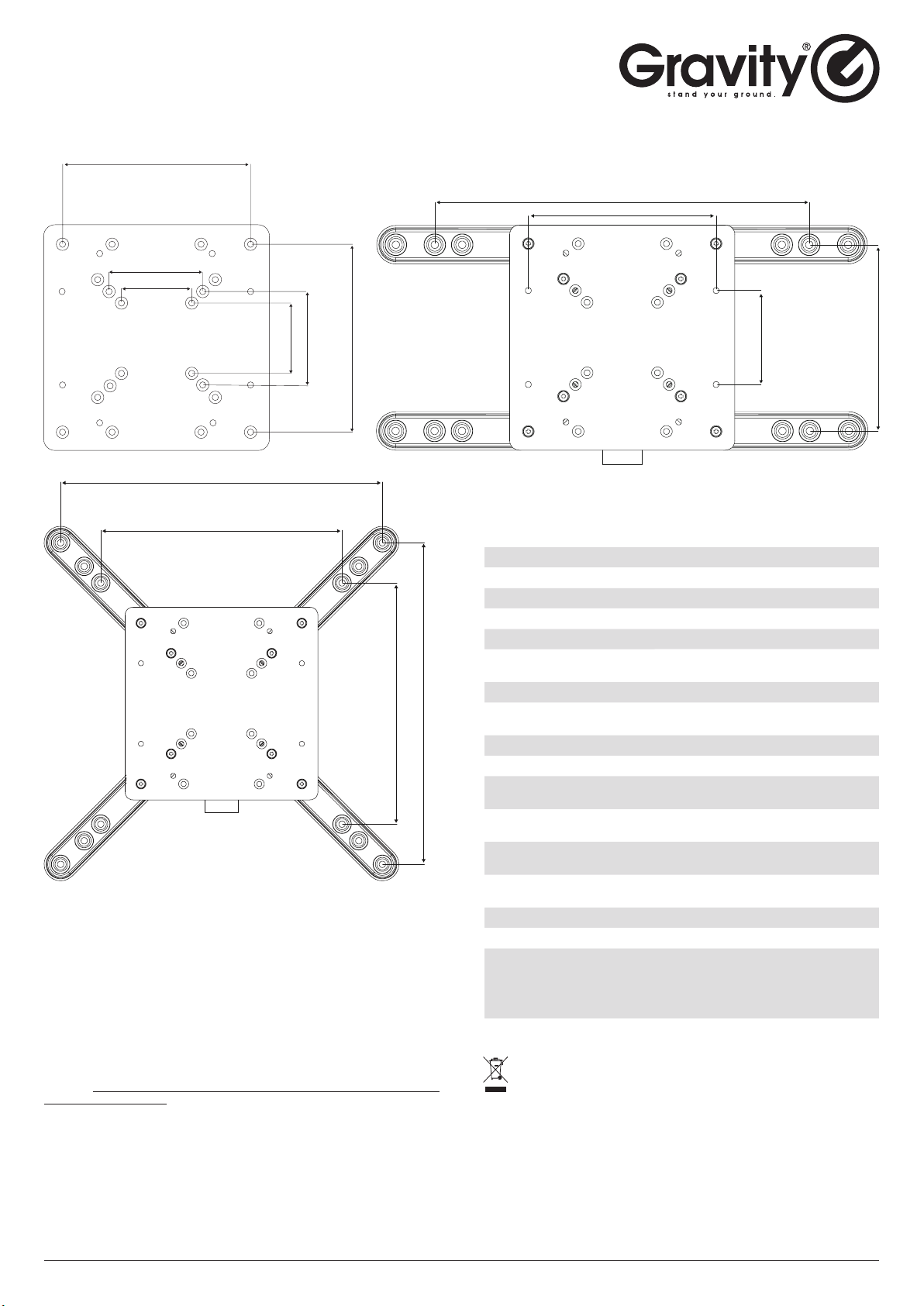
3B. Bei den VESA-Maßen 300 x 300, 400 x 200 und 400 x 400 müssen
zuerst die Erweiterungselemente mit den Auswölbungen Richtung
Monitor zeigend an den entsprechenden Positionen auf der Rück
seite der Basisplatte mit Hilfe der beiliegenden M6 Senkkopfschrauben befestigt werden (auf festen Halt achten!). Die korrekten
Positionen entnehmen Sie bitte den entsprechenden Zeichnungen
in dieser Anleitung. Legen Sie nun die Basisplatte mit den Erweiterungselementen mit der flachen Seite und der Flanschöffnung nach
unten zeigend auf die Monitorrückseite, in der Art, dass die Schraublöcher in den Erweiterungselementen und die Gewinde im Monitor
übereinander liegen. Falls der Monitor eine gewölbte Rückseite hat,
verwenden Sie bitte auch die beiliegenden Distanzstücke, um die
Halterung am Monitor zu befestigen.
4. Schrauben Sie mit Hilfe geeigneter Schrauben die Monitorhalter
ung an dem Monitor fest, achten Sie dabei unbedingt auf die Angaben unter WICHTIGE INFORMATIONEN UND SICHERHEITSHINWEISE
SPEZIFISCH ZUM PRODUKT in dieser Anleitung.
5. Heben Sie nun den Monitor mit Halterung auf ein geeignetes
Stativ (z.B. Boxenstativ) und arretieren die Verbindung mit Hilfe der
beiliegenden Griffschraube.
Adam Hall GmbH · Adam-Hall-Str. 1· 61267 Neu-Anspach · Germany
Tel.: (+49) 60 81 / 94 19 0 · Fax: (+49) 60 81 / 94 19 1000 · eMail: [email protected]
Page 4
GSA VESA 1
VESAADAPTER ZUR BILDSCHIRMMONTAGE
AN 35 MM STATIVROHREN
200
100
75
400
200
400
300
75 100 200
300
400
100 200
SPEZIFIKATION
Produktart Ständer und Stative Zubehör
Typ Universal-Monitorhalterung
Material Stahl
Oberäche pulverbeschichtet
Farbe schwarz
Geeignet für
Rohrdurchmesser
Belastbarkeit 30 Kg
geeignet für VESA Maße 200 x 100, 200 x 200, 300 x 300, 400 x 400,
Länge Basisplatte (mm) 240
Breite Basisplatte (mm) 240
Materialstärke Basisplatte
(mm)
Länge Erweiterungselemente
(mm)
Breite Erweiterungselemente
(mm)
Materialstärke
Erweiterungelemente (mm)
Austauschbare Ringe 1 x 25 mm
Schwarzer Ringsatz inkludiert Ja
Zubehör (im Lieferumfang) 4x Distanzstück, 8 x M6 Senkkopf-
Gewicht 2,71 kg
35 mm
100 x 100, 400 x 200, 75 x 75
3
240
45
2
schraube, 4 x Erweiterungselement, 4
x M6 Schrauben, 4 x M8 Schrauben,
Basisplatte mit 35 mm Stativansch und
Stellschraube
HERSTELLERGARANTIE & HAFTUNGSBESCHRÄNKUNG
Unsere aktuellen Garantiebedingungen und Haftungsbeschränkung finden
Sie unter: https://cdn-shop.adamhall.com/media/pdf/MANUFACTURERS-DEC
LARATIONS_GRAVITY.pdf
Im Servicefall wenden Sie sich bitte an Adam Hall GmbH, Adam-Hall-Str. 1,
61267 Neu Anspach / E-Mail [email protected] / +49 (0)6081 / 9419-0
Tel.: (+49) 60 81 / 94 19 0 · Fax: (+49) 60 81 / 94 19 1000 · eMail: [email protected]
Adam Hall GmbH · Adam-Hall-Str. 1· 61267 Neu-Anspach · Germany
KORREKTE ENTSORGUNG DIESES PRODUKTS
-
(Gültig in der Europäischen Union und anderen europäischen Ländern
mit Mülltrennung) Dieses Symbol auf dem Produkt oder dazugehörigen
Dokumenten weist darauf hin, dass das Gerät am Ende der Produktle
benszeit nicht zusammen mit dem normalen Hausmüll entsorgt werden darf,
um Umwelt- oder Personenschäden durch unkontrollierte Abfallentsorgung zu
vermeiden. Bitte entsorgen Sie dieses Produkt getrennt von anderen Abfällen
und führen es zur Förderung nachhaltiger Wirtschaftskreisläufe dem Recy
cling zu. Als Privatkunde erhalten Sie Informationen zu umweltfreundlichen
Entsorgungsmöglichkeiten über den Händler, bei dem das Produkt erworben
wurde, oder über die entsprechenden regionalen Behörden. Als gewerblicher
Nutzer kontaktieren Sie bitte Ihren Lieferanten und prüfen die ggf. vertraglich
vereinbarten Konditionen zur Entsorgung der Geräte. Dieses Produkt darf nicht
zusammen mit anderen gewerblichen Abfällen entsorgt werden.
-
-
 Loading...