


Zoom & ZT
Bagger
Owner/Operator Manual
Model
815040 34” Bagger
815041 42” Bagger
815042 50” Bagger
04444100B 4/12
Printed in USA
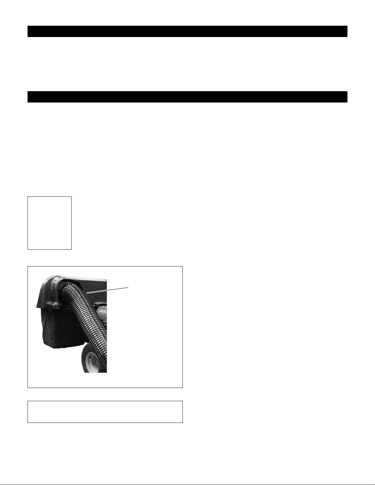
TABLE OF CONTENTS
Transfer
model & serial
number label
from product
registration
here.
Serial
Number
Label
Figure 1
Safety . . . . . . . . . . . . . . . . . . . . . . . . . . . . . . . . . . . . . 3
Assembly . . . . . . . . . . . . . . . . . . . . . . . . . . . . . . . . . . 7
Removal . . . . . . . . . . . . . . . . . . . . . . . . . . . . . . . . . . 14
Operation . . . . . . . . . . . . . . . . . . . . . . . . . . . . . . . . . 14
Maintenance. . . . . . . . . . . . . . . . . . . . . . . . . . . . . . . 15
INTRODUCTION
THE MANUAL
Before operation of unit, carefully and completely read
this Manual and the unit’s Owner/Operator Manual. The
contents will provide you with an understanding of safety
instructions and controls during normal operation and
maintenance.
All reference to left, right, front, or rear are given from
operator sitting in operation position and facing the
direction of forward travel.
MODEL AND SERIAL NUMBERS
When ordering replacement par ts or
making service inquiries, know the
Model and Serial numbers of your
unit.
Numbers are located on the product
registration form in the unit literatur e
package. They are printed on a serial
number label, located on the frame of
your unit.
Storage . . . . . . . . . . . . . . . . . . . . . . . . . . . . . . . . . . .16
Troubleshooting. . . . . . . . . . . . . . . . . . . . . . . . . . . .16
Specifications. . . . . . . . . . . . . . . . . . . . . . . . . . . . . .16
Parts List. . . . . . . . . . . . . . . . . . . . . . . . . . . . . . . . . .17
Warranty . . . . . . . . . . . . . . . . . . . . . . . . . . . . . . . . . .22
PRODUCT REGISTRATION
The Ariens/Gravely dealer must register the product at
the time of purchase. Registering the product will help the
company process warranty claims or contact you with the
latest service information. All claims meeting
requirements during the limited warranty period will be
honored, whether or not the product registration card is
returned. Keep a proof of purchase if you do not register
your unit.
Customer Note: If the dealer does not register your
product, please fill out, sign, and return the product
registration card to Ariens or go to www.ariens.com or
www.gravely.com.
UNAUTHORIZED REPLACEMENT PARTS
Use only Ariens/Gravely replacement parts. The
replacement of any part on this vehicle with anything
other than an Ariens/Gravely authorized replacement
part may adversely affect the performance, durability, or
safety of this unit and may void the warranty.
Ariens/Gravely disclaims liability for any claims or
damages, whether warranty, property damage, personal
injury or death arising out of the use of unauthorized
replacement parts.
• Record Unit Model and Serial numbers here.
DISCLAIMER
Ariens/Gravely reserves the right to discontinue, make
changes to, and add improvements upon its products at
any time without public notice or obligation. The
descriptions and specifications contained in this manual
were in effect at printing. Equipment described within this
manual may be optional. Some illustrations may not be
applicable to your unit.
DELIVERY
Customer Note: If you have purchased this product
without complete assembly and instruction by your
retailer, it is your responsibility to:
1. Read and understand all assembly instructions in
this manual. If you do not understand or have
difficulty following the instructions, contact your
nearest Ariens/Gravely Dealer for assistance.
sure all assembly has been properly completed and
safety interlock system works properly.
© Copyright 2012 Ariens Company
2
Make

NOTE: To locate your nearest Ariens Dealer, go to
Figure 2
OEe001
1
2
www.ariens.com on the internet. To locate your nearest
Gravely Dealer, go to www.gravely.com on the internet.
WARNING: Improper assembly or adjustments
can cause serious injury.
2. Understand all Safety Precautions provided in the
manuals.
SAFETY
3. Review control functions and operation of the unit.
Do not operate unit unless all controls function as
described in this manual.
4. Review recommended lubrication, maintenance
and adjustments.
5. Fill out a Product Registration Card and return the
card to the Ariens Company or go to
www.ariens. com or www.gravely.com.
SAFETY ALERTS
Look for these symbols to point out
important safety precautions. They mean:
Attention!
Personal Safe t y Is In v o lve d !
Become Alert!
Obey The Message!
The safety alert symbols above and signal words below
are used on decals and in this manual.
Read and understand all safety messages.
DANGER: IMMINENTLY HAZARDOUS
SITUATION! If not avoided, WILL RESULT in
death or serious injury.
WARNING: POTENTIALLY HAZARDOUS
SITUATION! If not avoided, COULD RESULT in
death or serious injury.
CAUTION: POTENTIALLY HAZARDOUS
SITUATION! If not avoided, MAY RESULT in
minor or moderate injury. It may also be used to
alert against unsafe practices.
REQUIRED OPERATOR TRAINING
Original purchaser of this unit was instructed by the seller
on safe and proper operation. If unit is to be used by
someone other than original purchaser; loaned, rented or
sold, ALWAYS provide this manual and any needed
safety training before operation.
NOTATIONS
NOTE: General reference information for proper
operation and maintenance practices.
IMPORTANT: Specific procedures or information
required to prevent damage to unit or attachment.
PRACTICES AND LAWS
Practice usual and customary safe working precautions,
for the benefit of yourself and others. Understand and
follow all safety messages. Be alert to unsafe conditions
and the possibility of minor, moderate, or serious injury or
death. Learn applicable rules and laws in your area.
Always follow the practices set forth in this manual.
3

1. WARNING!
OTt2080
OTt2070
Stop engine and wait for all moving parts to
stop before opening cover.
Avoid tip over and loss of control:
DO NOT overload bagger.
Use extreme caution on slopes.
DO NOT make abrupt turns or speed
changes.
• Weight kit is required when using bagger.
• Be aware of new turning radius.
2. CAUTION!
• Stop Engine Before Removing Tube, Boot, Or
Placing Hand Inside.
SAFETY RULES
Do not operate on slopes over 10°.
DO NOT operate mower unless guards are in place or
boot assembly and entire bagger are attached.
NEVER operate bagger if the unit’s safety interlock
system is not working properly.
Always be aware of maximum sweep of bagger when
turning. Always allow adequate clearance between
bagger, personnel and other objects when turning.
As grass catcher fills, be alert to changing unit stability
and control.
Always install front weight before operating u nit with
bagger attached.
Read, understand, and follow all safety practices in
Owner/Operator Manual before beginning assembly.
Failure to follow instructions could result in personal
injury and/or damage to unit.
ALWAYS remove key and/or wire from spark plug before
assembly. Unintentional engine start up can cause death
or serious injury.
Complete a walk around inspection of unit and work area
to understand:
• Work area • Your unit • All safety decals
Determine which attachments are needed and can be
used safely.
Inspect unit before each use for: missing or damaged
decals and shields, correctly operating safety interlock
system, and deterioration of grass bagger. Replace or
repair as needed.
ALWAYS check overhead and side clearances carefully
before operation. ALWAYS be aware of traffic when
operating along streets or curbs.
Keep children and people away.
Keep children out of work area and under watchful care
of a responsible adult.
Keep area of operation clear of all toys, pets, and debris.
Thrown objects can cause injury.
Check for weak spots on docks, ramps or floors. Avoid
uneven work areas and rough terrain. Stay alert for
hidden hazards or traffic.
DO NOT operate near drop-offs, ditches, or
embankments. Unit can suddenly turn over if a wheel is
over the edge of a cliff or ditch, or if an edge caves in.
Data indicates that operators, age 60 and above, are
involved in a larger percentage of riding mower related
injuries. These operators should evaluate their ability to
operate the riding mower safely enough to protect
themselves and others from serious injury.
Read the entire Owner/Operator manual and other
training material. If the operator or the mechanic cannot
read the manual, it is the owner’s responsibility to explain
it to them. Only the user can prevent and is responsible
for accidents or injuries occurring to themselves, other
people or property.
Only trained adults may operate or service unit. Training
includes actual oper ation.
Local regulations may restrict the age of the operator.
NEVER allow children to operate or play on or near unit.
Be alert and shut off unit if children enter area.
NEVER operate unit after or during the use of
medication, drugs or alcohol. Safe operation requires
your complete and unimpaired attention at all times.
DO NOT wear loose clothing or jewelry and tie back hair
that may get caught in rotating parts.
Wear adequate outer garments.
NEVER wear open sandals or canvas shoes during
operation. Wear adequate safety gear, protective gloves
and footw ear.
Wear proper footwear to improve footing on slippery
surfaces.
Always wear safety goggles or safety glasses with side
shields when operating mower.
Moving parts can cut or amputate fingers or a hand.
Wrap blade(s) or wear gloves to service. On multiblade
mowers, rotation of one blade will cause all blades to
rotate.
NEVER place your hands or any part of your body or
clothing inside or near any moving part while unit is
running.
ALWAYS keep hands and feet away from all rotating
parts during operation. Rotating parts can cut off body
parts.
ALWAYS keep body and hands away from pin holes or
nozzles which eject hydraulic fluid under pressure.
DO NOT touch parts which are hot. Allow parts to cool.
ALWAYS keep hands and feet away from all pinch
points.
Fumes from the engine exhaust can cause death or
serious injury. DO NOT run engine in an enclosed area.
Always provide good ventilation.
Read, understand, and follow all instructions in the
manual and on the machine before starting.
4

Understand:
• How to operate all controls
• The functions of all controls
• How to STOP in an emergency
• Braking and steering characteristics
• Turning radius and clearances
Keep safety devices or guards in place and functioning
properly. NEVER modify or remove safety devices.
Do not operate without either entire bagger or the
discharge chute in place.
Stop engine before removing grass catcher or unclogging
chute.
Ensure Safety Interlock System is functioning properly.
DO NOT operate unit if safety interlock is damaged or
disabled.
Start and operate unit only when seated in operator’s
position. Steering control levers must be in neutral, PTO
disengaged and parking brake set when starting engine.
Use care when approaching blind corners, shrubs, trees
or other objects that may obscure vision.
Dust, smoke, fog, etc. can reduce vision and cause an
accident. Mow only in daylight or good artificial light.
Avoid slippery surfaces. Always be sure of your footing.
DO NOT mow on wet grass. Reduced traction could
cause sliding and effect the machine’s stability.
Watch for traffic when operating near or crossing
roadways.
Never carry passengers.
DO NOT try to stabilize the machine by putting your foot
on the ground.
Never direct discharge towards persons or property that
may be injured or damaged by thrown objects. Use
extreme caution on gravel surfaces.
Always stand clear of the discharge area.
ALWAYS disengage PTO, stop unit and engine, remove
key, engage parking brake and allow moving parts to
stop before leaving operator ’s posi ti on.
Never engage PTO while raising attachment or when
attachment is in raised position.
DO NOT operate at too fast a rate. DO NOT change
engine governor settings or over-speed engine. Slow
down before turning.
DO NOT operate in reverse unless absolutely necessary.
ALWAYS look down and behind before and while
backing.
Stop and inspect equipment if you strike an object or if
there is an unusual vibration. Repair, if necessary, before
restarting. Never make adjustments or repairs with the
engine running.
Mower blades are sharp and can cut you. Wrap the
blade(s) or wear gloves, and use extra caution when
servicing them. NEVER weld or straighten mower blades.
Rotation of one blade may cause rotation of the other
blades.
Take all possible precautions when leaving unit
unattended. Shut off engine. Remove wire from spark
plug and secure it away from spark plug.
ALWAYS remove key to prevent unauthorized use.
Know the weight of loads. Limit loads to those you can
safely control and the unit can safely handle.
Disengage PTO when attachment is not in use. ALWAYS
turn off power to attachment when travelling, crossing
driveways, etc.
Mow up and down slopes, not across them.
Keep all movements on the slope slow and gradual. Do
not make sudden changes in speed or direction.
Avoid starting or stopping on the slope. If tires lose
traction, disengage the blades and proceed slowly
straight down the slope.
If you cannot back up a slope or you feel uneasy on it, do
not mow it.
DO NOT park on slopes unless necessary. When parking
on slope always chock or block wheels. Always set
parking brake.
Use a slow speed. Tires may lose traction on slopes
even though the brakes are functioning properly.
Do not bypass transmission when on a slope.
Tow only with a machine that has a hitch designed for
towing. Do not attach towed equipment except at the
hitch point.
Follow the manufacturer’s reco mme nda tion s for weigh t
limits for towed equipment and towing on slopes.
NEVER allow children or others in or on towed
equipment.
On slopes, the weight of the towed equipment may cause
loss of control.
Travel slowly and allow extra distance to stop.
Use extra care when loading or unloading unit onto trailer
or truck.
Secure unit chassis to transpor t vehicle. NEVER secure
from rods or linkages that could be damaged.
DO NOT transport machine while engine is running.
ALWAYS turn off power to attachment and shut off fuel
when transporting unit.
Keep unit free of debris. Clean up oil or fuel spills.
This product is equipped with an internal combustion
type engine. DO NOT use unit on or near any
unimproved, forest-covered or brush covered land unless
exhaust system is equipped with a spark arrester
meeting applicable local, state or federal laws. A spark
arrester, if it is used, must be maintained in effective
working order by operator.
Fuel is highly flammable and its vapors are explosive.
Handle with care. Use an approved fuel container.
NO smoking, NO sparks, NO flames. ALWAYS allow
engine to cool before servicing.
NEVER fill fuel tank when engine is running or hot from
operation.
5

NEVER fill or drain fuel tank indoors.
Replace fuel cap securely and clean up spilled fuel.
Never fill containers inside a vehicle or on a truck or
trailer bed with a plastic liner. Always place containers on
the ground away from your vehicle before filling.
When practical, remove gas-powered equipment from
the truck or trailer and refuel it on the ground. If this is not
possible, then refuel such equipment on a trailer with a
portable container, rather than from a gasoline dispenser
nozzle.
Keep the nozzle in contact with the rim of the fuel tank or
container opening at all times until fueling is complete.
Do not use a nozzle lock-open device.
If fuel is spilled on clothing, change clothing immediately.
Avoid Electric Shock. Objects contacting both battery
terminals at the same time may result in injury and unit
damage. DO NOT reverse battery connections.
Reverse connections may result in sparks which can
cause serious injury. Always connect positive (+) lead of
charger to positive (+) terminal, and negative (-) lead to
negative (-) terminal.
ALWAYS disconnect negative (-) cable FIRST and
positive (+) cable SECOND. ALWAYS connect positive
(+) cable FIRST, and negative (-) cable SECOND.
Explosive Gases from battery can cause death or serious
injury. Poisonous battery fluid contains sulfuric acid and
its contact with skin, eyes or clothing can cause severe
chemical burns.
No flames, No sparks, No smoking near battery.
ALWAYS wear safety glasses and protective gear near
battery. Use insulated tools.
DO NOT TIP battery beyond a 45° angle in any direction.
ALWAYS keep batteries out of reach of children.
Battery posts, terminals and related accessories contain
lead and lead compounds, chemicals known to the State
of California to cause cancer and reproductive harm.
Wash hands after handling.
ALWAYS block wheels and know all jack stands are
strong and secure and will hold weight of unit during
maintenance.
Release pressure slowly from components with stored
energy.
NEVER attempt to make any adjustments to unit while
engine is running (except where specifically
recommended). Stop engine, remove key or spark plug
wire and wait for all moving parts to stop before servicing
or cleaning.
Check parking brake operation frequently. Adjust and
service as required.
ALWAYS maintain unit in safe operating condition.
Damaged or worn out muffler can cause fire or explosion.
Maintain or replace safety and instruction labels, as
necessary.
NEVER store unit with fuel in fuel tank, inside a building
where any ignition sources are present.
Shut off fuel and allow engine to cool completely before
storing in closed area or covering unit.
Clean grass and debris from unit, especially from around
muffler and engine, to help prevent fires.
For extended storage, shut off fuel and clean unit
thoroughly. See engine manual for proper storage.
Lower cutting deck unless a positive mechanical lock is
used.
Use only attachments or accessories designed for your
unit.
Check all hardware at regular intervals, especially blade
attachment bolts. Keep all hardware properly tightened.
Check attachment components frequently. If worn or
damaged, replace with manufacturer’s recommended
parts.
6
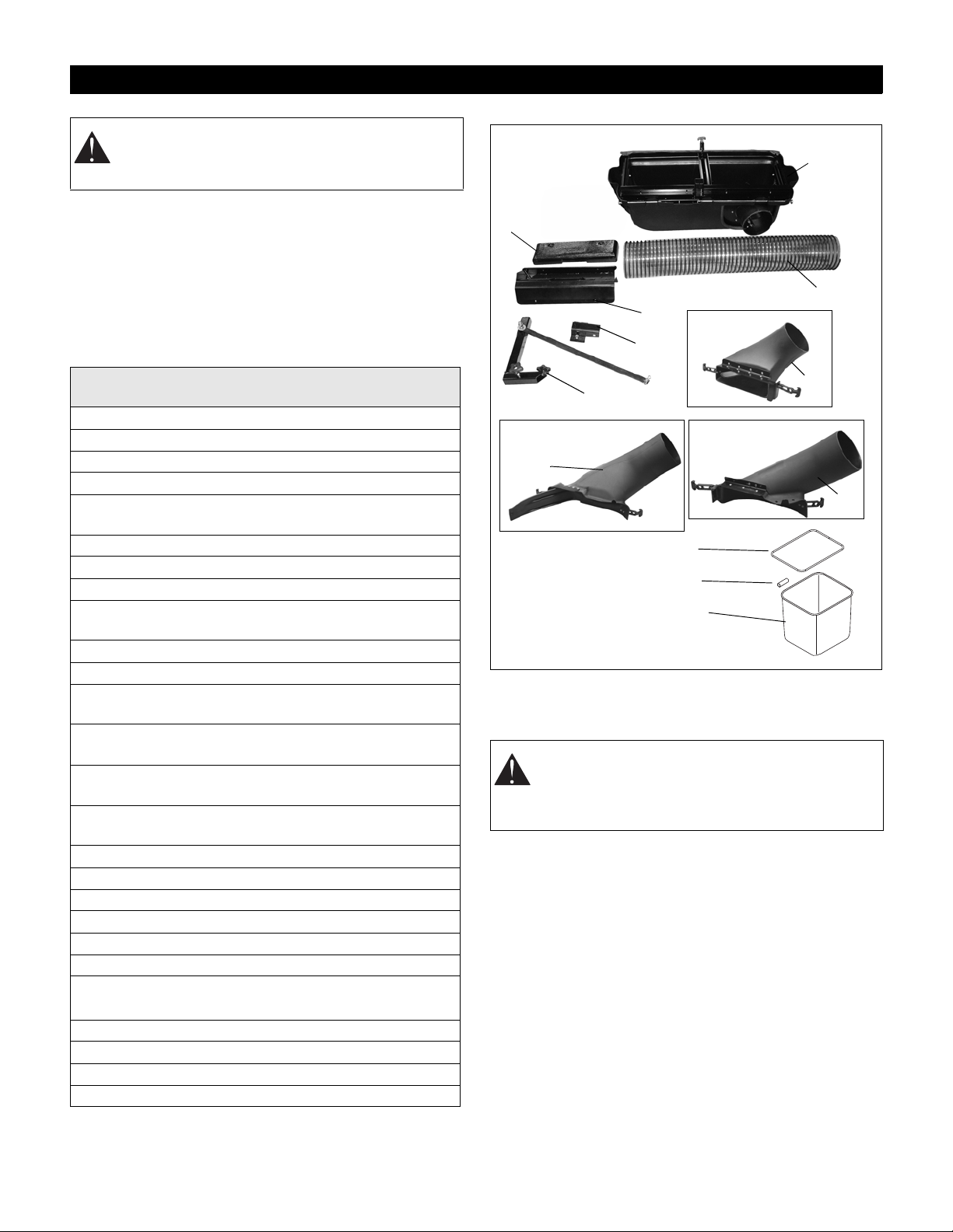
ASSEMBLY
Figure 3
22
18
19
20
21
4
1
18
18
815040
815041
815042
2
23
24
WARNING: AVOID INJURY. Read and
understand the entire Safety section before
proceeding.
UNPACKING UNIT
IMPORTANT: Remove contents from carton carefully.
Place cover assembly on a flat piece of cardboard to
avoid scratching it.
Package Contents:
Check the contents of your kit for the parts listed below
and shown in Figures 3 – 6.
Item Description
1 Weldment Bagger Weight Tray 1 04215451
2 Mesh Bag 2 03862900
3 Grip, Adhesive 1 03833800
4 Cast Iron Weight 1 00172000
5 5/16 x 1" Round Head Square
Neck Bolt
6 5/16-18 Nyloc Nut 2 06545400
7 3/8-16 x 3" Hex Bolt 2 05957800
8 3/8" Lock Washer 4 06308800
9 1/2 x 2" Round Head Square
Neck Bolt
10 1/2" Nyloc Flange Nut 4 06500010
11 1/2" Push Nut 2 06500705
12 .515 x 1.625 x .250 Flat Steel
Washer
13 .438 x 1.00 x .083 Flat Steel
Washer
14 .390 x 1.5 x .125 Flat Steel
Washer
15 Locking Bow Tie Cotter Pin
.091 x 7.875
16 Wing Knob 1 07500225
17 Studded Wing Kn ob 1 07500226
18 34" Boot Assembly (815040) 1 51577500
42" Boot Assembly (815041) 1 51577600
50" Boot Assembly (815042) 1 51577700
19 L Bracket, Brace & Hardware 1 N/A
20 Bagger Hose (815040)
Bagger Hose (815041, 042)
21 Hood Assembly 1 51577800
22 Receiver & Hardware 1 N/A
23 Bag Frame 2 00663200
24 Plastic Tube, 3/8 x 1/2 x 3" 2 00677000
Qty Part
Number
2 06216100
2 06200205
6 06445000
4 06435900
2 06441700
4 06700201
1 04445600
04222900
INSTALL FRONT WEIGHT TRAY &
COUNTERWEIGHT
WARNING: ALWAYS install counterweight
before operating unit with bagger attached.
ALWAYS remove counterweight when bagger is
removed from unit.
1. Remove the front footrest. There are two 1/2 x 2"
(item 9) and 5/16 x 1" (item 5) round head square
neck bolts that secure the footrest to the chassis.
The 1/2 x 2" bolts (item 9) and metal spacers are
held on the footrest by two 1/2" push nuts (item 11).
Twist or cut off the push nuts to remove. Save the
spacers and discard all other hardware. See
Figure 4.
2. Lay the footrest onto the back of the weight tray
(similar profile). It may be helpful to have the weight
tray laying upside down on the ground when mating
it to the footrest. Install two 1/2 x 2" bolts (item 9)
thru the front of the weight tray and footrest. Slide
the two spacers (from step 1) over the bolts and
secure with push nuts (item 11). Secure the push
nuts as tight as possible. See Figure 4.
7
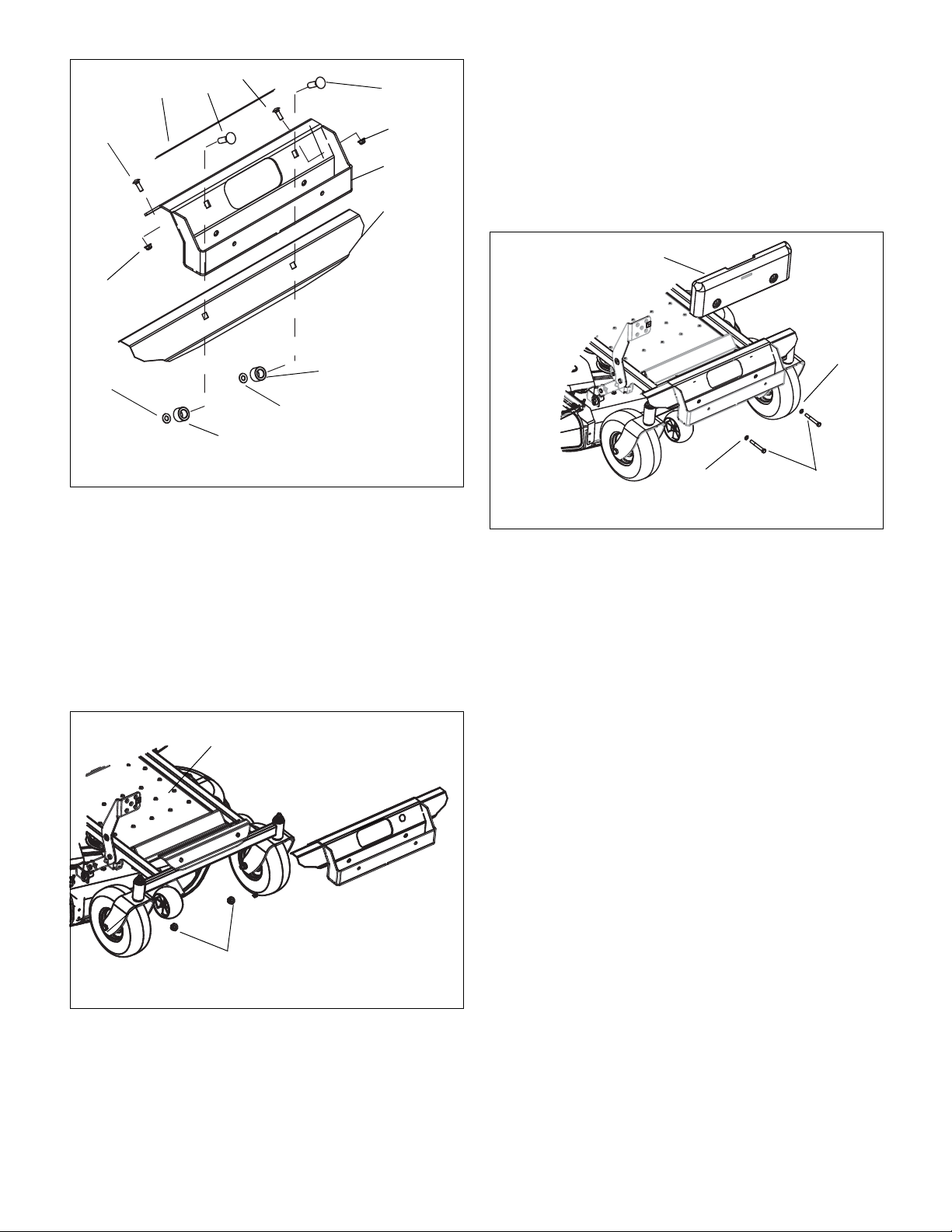
3. Place the footrest/weight tray assembly over the
Figure 4
Front Footrest
11
6
Spacer
1
6
9
5
3
5
9
Spacer
11
Figure 5
10
6
3
Figure 6
8
7
8
4
chassis. The two 1/2 x 2" bolts (item 9) will drop
through the two holes in the chassis. It may be
necessary to tilt the assembly back slightly to align
the bolts with the holes. Secure with two 1/2" nyloc
flange nuts (item 10). See Figure 5.
4. Install two 5/16 x 1" bolts (item 5) through the two
holes on the footrest portion of the assembly.
Secure with two 5/16 nyloc flange nuts. Adhere the
grip adhesive (item 3) just above the two bolts
(item 5) on the footrest. See Figure 4.
5. Place the cast iron weight (item 4) into the weight
tray. Install two 3/8 x 3" hex bolts (item 7) and two
3/8" lock washers (item 8) through the front of the
weight. There are two weld nuts on the back of the
weight tray. Thread the bolts into the weld nuts and
tighten until the lock washers engage. Do not
overtighten the bolts or the tray will flex. The bolts
are only inst a lle d to prev ent the weig ht s fr om f alli ng
out of the tray. See Figure 6.
8

INSTALLING BAGGER BOOT
Figure 7
Front
Deck
Post
Front Boot Strap
Boot Bracket
Slide boot
bracket under
discharge
chute.
Secure boot by
hooking boot
straps to front and
rear deck posts.
Boot
Figure 8
Bagger Boot
Connect rear
boot strap to
deck post.
Connect front
boot strap to
deck post.
(815040 ONLY)
NOTE: Discharge chute can remain attached to deck.
WARNING: On multi-blade mowers, rotation of
one mower blade will cause all blades to rotate.
WARNING: Mower blades are sharp and can
cut you. Wrap the blades or wear gloves, and
use extra caution when servicing them.
INSTALL BAGGER BOOT
(815041 ONLY)
1. Lift discharge chute and insert discharge bagger
boot into deck discharge opening. See Figure 8.
NOTE: Discharge chute can remain attached to deck.
1. Slide boot bracket under discharge chute bracket.
See Figure7.
2. Using front and rear boot straps, secure the boot by
attaching boot straps to deck posts. See Fi gure 7.
2. Insert bagger boot fully into opening making sure
that the front of the boot is positioned inside of the
deck shell and the top edge of the boot is
positioned on top of the deck shell and below the
discharge chute. See Figure 8.
3. Push the bagger boot fully into the discharge
opening and attach the rear boot strap to the rear
attaching post. See Figure 8.
4. Attach the boot front strap to the front attaching
post. See Figure 8.
9

INSTALL BAGGER BOOT
Figure 9
Boot
Bracket
Front Deck Bolt
Connect rear
boot strap to
deck post.
Discharge
Chute
Rear Deck Bolt
Front Boot Hole
Boot Notch
Connect front
boot strap to
deck post.
(815042 ONLY)
1. Lift discharge chute and slide bagger boot bracket
under discharge chute. See Figure 9.
NOTE: Discharge chute can remain attached to deck.
2. Insert bagger boot fully onto discharge opening
making sure that the hole and notch in the top of the
boot line up over exposed deck bolts. See Figure 9.
3. Attach rear boot strap to the rear attaching post.
See Figure 9.
4. Attach front boot strap to the front attaching post.
See Figure 9.
10

INSTALL FRAME AND HOOD ASSEMBLY
Figure 10
Receiver
3/8 x 1" Hex Bolt &
3/8" Locking Nut
Figure 11
1/2" Studded Wing Knob
L Bracket
1/2 x 2 3/4" Hex Bolt &
1/2" Wing Knob
Figure 12
L Bracket
Hood
Assembly
Figure 13
Support Bar
Engine Control Cables
1/2 x 2 3/4" Hex
Bolt,
1/2" Flat
Washer &
1/2" Flange Nut
1. Install receiver to the right rear frame using two 3/8
x 1" hex bolts and two 3/8" locking nuts. Tighten
hardware. See Figure 10.
2. Insert L bracket into the receiver and fasten using
1/2 x 2 3/4" round head square neck bolt and wing
knob. Do not fully tighten. See Figure 11.
3. Install front studded wing knob into front of receiver.
Tighten studded wing knob and hardware installed
in step 2.
NOTE: It may require two people to position hood
assembly onto bracket.
5. Position bagger support bar inside of engine control
cables and attach support bar to L bracket using 1/2
x 2 3/4" hex bolt, 1/2" flat washer and 1/2" flange
nut. Flat washer is positioned between bar and L
bracket. Do not fully tighten hardware. See
Figure 13.
4. Position hood assembly over L bracket and install
onto bracket. See Figure 12.
6. Mount front of support bar to the mower frame
using 3/8 x 3/4" clevis pin, 3/8" washer and bow-tie
locking cotter pin. Tighten hardware installed in step
5. See Figure 14.
11

Figure 14
Clevis
Pin
3/8" Washer & Bow-Tie
Locking cotter Pin (Not Shown)
Figure 15
Thread bag frame (23) through sleeve
in mesh bag (2).
Install 3/8 x 1/2 x 3" plastic tube (24)
on each end of frame and push the
ends together.
CAUTION: MAKE SURE the heat resistant
(smooth side) side of the mesh bags are facing
the unit.
INSTALL BAG ON FRAME (FIGURE 15)
1. Thread the bag frames (23) through the sleeve on
the open end of the mesh bag (2).
2. Install the 3/8 x 1/2 x 3" plastic tubes (24) on the
ends of the bag frames and push then ends
together. on the ends of the bag frame and push
the ends together.
NOTE: The rope handle on the bottom of the bag will
point to the outside when the bag is assembled correctly.
12

3. Install mesh bags to bagger frame. Make sure that
Figure 16
MAKE SURE the heat resistant side
(smooth side) faces the unit.
Mesh Bags
Figure 17
Latch
Strap
Figure 18
Thumb Latch
Bagger Hose
the heat-resistant side of the mesh bags face the
unit.
4. Close hood assembly and connect latch strap.
Install Hose
1. Install bagger hose on bagger boot assembly and
2. F lip up thumb latc h and pus h b agg er hose int o the
bagger cover assembly.
latch. Flip down the latch, making sure the latch is
attached to a rib on the hose. See Figure 18.
13

REMOVAL
Figure 19
Airflow
Restricted
Airflow
Unrestricted
Airflow
Indicator
WARNING: AVOID INJURY. Read and
understand the entire Safety section before
proceeding.
1. F lip up thumb latc h and re move bagg er hose from
bagger cover assembly and bagger boot assembly
(see figure 18 on page 13).
2. Remove bagger boot assembly.
WARNING: AVOID INJURY. Read and
understand the entire Safety section before
proceeding.
CAUTION: Do not tow anything with the hitch
when the bagger is installed.
BEFORE EACH USE
1. Check bagger parts for wear, deterioration, or
damage. Replace ONLY with Ariens/Gravely
original service parts before operating.
2. Make sure the cast iron weight is installed.
3. Ensure all hardware is tight.
4. Remove any grass buildup from bagger parts.
5. Ensure hose is fastened securely on boot
assembly.
6. Ensure grass bagger baskets are installed, and the
bagger cover is closed and securely latched.
3. Remove mesh bags (see figure 16 on page 13).
4. Remove bagger frame and cover assembly, bagger
strap and all mounting hardware. The receiver and
the front weight tray can remain on the unit for
further use.
5. Remove the cast iron weight from the front weight
tray.
OPERATION
AIRFLOW INDICATOR (FIGURE 19)
When the airflow indicator is pointed straight up, the air is
restricted which indicates one or more possible
problems:
• The grass bagger baskets are full and need to be
emptied. See Emptying Mesh Bags on page 14.
• There is a clog in the bagger. See Unclogging
Bagger on page 15.
When the airflow indicator is facing forward, the air is
unrestricted indicating that the grass bagger baskets are
not full and there are no clogs in the bagger.
OPERATING THE BAGGER
Starting
1. Start engine and engage PTO (see unit’s
Operator’s Manual).
2. Set throttle to full.
3. Set mower deck height.
4. Choose a slow ground speed.
Shutting Off
WARNING: Lower attachment, stop engine, and
remove key to prevent unauthorized use. DO
NOT park on slopes.
1. Allow the mower blades to run for at least 30
seconds to clear boot assembly and hose of debris.
2. Disengage PTO.
3. Shut off unit (see unit’s Operator’s Manual).
EMPTYING MESH BAGS
If bagger stops picking up grass clippings, the mesh bags
may be full.
14

WARNING: NEVER open cover asse mbly wh ile
Figure 20
the engine is running and the PTO is engaged.
ALW AYS shut off engine prior to emptying mesh
bags.
To empty grass bags:
1. Disengage PTO, stop engine, and remove ignition
key. W ait for all moving parts to stop before leaving
operator’s position.
2. Disconnect latch strap and open cover and remove
each mesh bag from bagger frame.
1. Stop engine and remove ignition key. Wait for all
moving parts to stop.
2. Flip thumb latch and remove hose.
3. Remove grass from hose and boot assembly.
4. Install hose and secure with thumb latch.
OPERATING TIPS
IMPORTANT: DO NOT remove more than 1 1/4” (3.2 cm)
of grass when bagging.
• Cut grass when it is dry.
• Cut grass in two passes when cutting thick, long, or
wet grass. Make the first cut higher than desired.
Make the second cut at desired height.
• Always use full throttle when bagging.
• Adjust ground speed as needed to allow the bagger
to pick up debris.
MAINTENANCE
WARNING: AVOID INJURY. Read and
understand the entire Safety section before
proceeding.
3. Empty the grass from each mesh bag.
4. Install mesh bags back on bagger frame. Make
sure that the heat-resistant side of the mesh bags
face the unit.
5. Close and latch cover.
UNCLOGGING BAGGER
WARNING: MOVING PARTS can cut or
amputate body parts.
NEVER attempt to clear boot assembly while
engine is running.
ALWAYS stop engine, remove key, and wait for
moving parts to stop.
Sharp edges can cut. Movement of parts can
cut off fingers or a hand. Wrap blade(s), wear
sturdy gloves and use extreme caution when
working near blades.
Ariens/Gravely Dealers will provide any service or
adjustments which may be required to keep your unit
operating at peak efficiency.
Interval Task Action
Each
Use
Check
counter
weight
Check
Hose
Check
mesh
bags
Check
Fasteners
Inspect
Bagger
Parts
Clean Unit Clear away debris in boot
Ensure the cast iron weight
is installed and securely
fastened.
Ensure hose is securely
fastened to cover assembly and
boot assembly.
Ensure mesh bags are installed,
and bagger cover is closed and
securely latched.
Ensure all hardware is tight. Pay
special attention to the guards
and safety shields.
Inspect bagger parts for holes,
abrasions, or structural damage.
Replace any worn or damaged
parts with Ariens/Gravely service
parts.
assembly, in tube, and in cover
assembly.
If hose or boot assembly become clogged, stop forward
motion and allow unit to clear itself. If unit will not clear
itself, unclog the hose and/or boot assembly manually as
instructed below.
15

STORAGE
WARNING: AVOID INJURY. Read and
understand the entire Safety section before
proceeding.
IMPORTANT: NEVER spray unit with high-pressure
water. DO NOT store unit outdoors.
Clean plastic surfaces with sponge and mild detergent.
Dry with a soft cloth.
Clear away debris under belt cover, in boot assembly, in
tube, and in cover assembly before storing.
Remove all dirt, grease, leaves, etc. from unit.
Store in a clean, dry area.
Ensure all fasteners are properly tightened. Inspect
moving parts for damage and wear.
Touch up all rusted or chipped painted surfaces.
TROUBLESHOOTING
Problem Probable Cause Correction
Airflow
indicator
points
straight
up.
Bagger
fails to
pick up
grass or
leaves.
1.Air flow is
restricted.
1.The grass bagger
baskets are full.
2.Bagger is
clogged.
1.The grass bagger
baskets are full
(see Emptying
Mesh Bags on
page 14).
2. The bagger is
clogged (see
Unclogging
Bagger
page 15).
on
1.Empty g ra ss
bagger baskets
(see Emptying
Mesh Bags on
page 14).
2.Unclog bagger
(see Unclogging
Bagger on
page 15).
SPECIFICATIONS
Model Number 815040
Description Non-Powered Bagger
Serial Number 000101 and up
Added Length to Unit 19 5/8 in. (49.8 cm)
Added Width to Unit 10 in. (25.4 cm)
Added Weight to Unit 129 lb. (58.5 kg)
For Use on Models 915146, 157, 168, 169
(S/N 10,000 & up)
Model Number 815041
Description Non-Powered Bagger
Serial Number 000101 and up
Added Length to Unit 19 5/8 in. (49.8 cm)
Added Width to Unit 13 in. (33 cm)
Added Weight to Unit 129 lb. (58.5 kg)
For Use on Models 915148, 159, 170, 171
(S/N 10,000 & up)
Model Number 815042
Description Non-Powered Bagger
Serial Number 000101 and up
Added Length to Unit 19 5/8 in. (49.8 cm)
Added Width to Unit 8 in. (20.3 cm)
Added Weight to Unit 129 lb. (58.5 kg)
For Use on Models 915150, 161
(S/N 10,000 & up)
16

SAFETY DECALS
OEe002
1
2
PARTS LIST
Item Part No. Qty. Description
1 05359700 1 Decal, Bagger Cover
2 07897700 1 Decal, Boot Caution
17

BAGGER HOOD
PREASSEMBLED IN KIT 51577800
15
13
19
18
14
12
11
8
1
11
2
9
9
10
9
16
6
5
7
3
10
9
10
9
10
17
BOM ID Number Qty Description
1 04409600 1 COVER, 2-BUCKET BAGGER
2 04409900 1 SEAL, UPPER BOOT
3 04410051 1 WLDMT, BAGGER HOOD VENT, LH
4 04410700 1 SEAL, BULB - BAGGER HOOD
5 04431051 1 WLDMT, BAGGER HOOD VENT, RH
6 04439500 1 SEAL, BULB
7 04439751 1 WLDMT, TUBE SUPPORT
8 04446800 1 BOOT, UPPER
9 06116700 5 SCR-MCH 10-24X.50 HWH YWZC
10 06116900 5 SCR-MCH 10-24X.75 HWH YWZC
11 06442700 25 WSHR-FL-STL
4
20
BOM ID Number Qty Description
12 06536000 8 NUT-LK-NYL #10-24 YWZC
13 06714800 1 PIN-HAIR, ENDRIES #25 YWZC
14 06800108 17 RVT-POP .187x.375
15 06815300 1 PIN, CLEV .309X1.62 YWZC
16 07411500 2 SCR-TAP .31-18X.50 HWH TR YWZ
17 09079500 1 LATCH, RUBBER
18 07000026 1 LATCH, THUMB
19 00168300 1 INDICATOR, FLOW
20 04445600 1 BAGGER TUBE (815040)
04222900 1 BAGGER TUBE (815041, 042)
18

BAGGER LOWER BOOT
MODEL 815040
PREASSEMBLED IN KIT 51577500
5
2
4
6
1
3
BOM ID Number Qty Description
1 04433200 1 BAGGER, BOOT MOLDED
2 04449751 1 BRKT, BOOT 34" ZOOM/ZT
3 06116900 4 SCR-MCH 10-24 x .75 HWH YWZC
4 06442700 8 WSHR-FL-STL .219 x .500 x .049 YWZC
5 06803800 8 RVT-POP .187 x .375
6 09079500 2 LATCH, RUBBER
MODEL 815041
PREASSEMBLED IN KIT 51577600
8
7
2
1
5
4
9
6
5
3
4
BOM ID Number Qty Description
1 04392000 1 BOOT, BAGGER ,42" TUNNEL DECK
2 04449651 1 WLDMT, BOOT 42" ZOOM/ZT
3 04513051 1 BRKT, BOOT REINFORCEMENT
4 06116900 4 SCR-MCH 10-24X.75 HWH YWZC
5 06442700 5 WSHR-FL-STL.219X.500X.049YWZC
6 06536000 1 NUT-LK-NYL #10-24 YWZC
7 06803800 4 RVT-POP .187x.375
8 09079500 2 LATCH, RUBBER
9 05960800 1 BLT-HEX 10-24X 1.0 YWZC
8
3
BOM ID Number
1 04432300
2 04449551
3 06442700
4 06803800
5 09079500
6 06116900
MODEL 815042
PREASSEMBLED IN KIT 51577700
4
2
1
6
Qty Description
1 BAGGER, BOOT MOLDED
1 BRKT, BOOT 50" ZOOM/ZT
5 WSHR-FL-STL .219 x .500 x .049 YWZC
5 RVT-POP .187 x .375
2 LATCH, RUBBER
4 SCR-MCH 10-.75 HWH YWCZ
5
19

BAGGER FRAME
8
6
19
9
21
2
1
16
15
13
11
3
24
7
22
23
10
5
20
14
18
BOM ID Number Qty Description
1 03844151 1 OVERLAP PLATE, BAGGER FRAME
2 04409551 1 ASM, BAGGER FRAME UPPER
3 04409751 1 BRKT, RECEIVER SLEEVE INSERT
4 04409851 1 BRKT, RECEIVER LOWER
5 04410551 1 BRKT, BAG FRAME SUPPORT BAR
6 04439500 2 SEAL, BULB
7 04443400 1 PIN, BAGGER HINGE (L)
8 04443500 1 PIN, BAGGER HINGE (R)
9 04446700 1 SEAL, HINGE
10 05948700 2 BOLT-HEX-Gr5-UNC-YWZC
11 05965500 1 BOLT-HEX-Gr5-UNC-YWZC
12 06225700 1 BLT-RDHDSQNK .50-13X2.75 G5 Y
13 06430200 1 WSHR-FL-STL .531X1.250X.100 YWZC
12
4
17
BOM ID Number Qty Description
14 06436200 1 WSHR-FL-STL.406X.812X.065 YWZ
15 06442700 3 WSHR-FL-STL.219X.500X.049YWZC
16 06500010 1 NUT-LK-NYL-FLG .50-13 YWZC
17 06545500 2 NUT-LK-NYL-FLG .38-16 YWZC
18 06700201 1 PIN, BOWTIE LOCKING .091X1.875
19 06803800 3 RVT-POP .187x.375
20 06814800 1 PIN-CLEV .38X.75 YWZC
21 07411500 2 SCR-TAP .31-18X.50 HWH TR YWZ
22 07500225 1 KNOB, WING
23 07500226 1 KNOB, WING STUDDED
24 06714800 2 PIN-HAIR, ENDRIES #25 YWZC
* Frame Kit #51577900 Includes items 2 and 6.
20

COUNTERWEIGHT ASSEMBLY
1
2
5
8
6
3
4
10
9
7
Item Part No. Qty. Description
1 04215451 1 Weldment, Bagger Weight Tray
2 00172000 1 Cast Iron Weight
3 06200205 2 Bolt, Round Head Square Neck 1/2-13 x 2.00
4 06216100 2 Bolt, Round Head Square Neck 1/2-13 x 1.00
5 03833800 1 Grip, Adhesive
6 05957800 2 Bolt, Hex 3/8-16 x 3.00
7 06308800 2 Washer, Lock 3/8
8 06545400 2 Nut, Nyloc 5/16-18
9 06500705 2 Nut, Push
10 06500010 2 Nut, Flange Nyloc 1/2-13
21

Consumer Mowing Equipment
Limited Warranty
Ariens Company (Ariens) warrants to the original purchaser that Ariens, Gravely and Countax brand lawn and garden
consumer products purchased on or after 1/1/2012 will be free from defects in material and workmanship for the time period
noted in the chart below. Equipment put to personal use around a single household or residence is considered “Consumer
Use”; equipment put to any business use (agricultural, commercial, or industrial) or used at multiple locations is considered
“Commerc ial Use.” If any product is rented or leased, then the duration of these warranties shall be 90 days af ter the da te of
purchase.
An authorized Ariens dealer (Ariens brand products), Gravely dealer (Gravely brand products), or Countax dealer (Countax
brand products) will repair any defect in material or workmanship, and repair or replace any defective part, subject to the
conditions, limitations and exclusions set forth herein. Such repair or replacement will be free of charge (labor and parts) to
the original purchaser except as noted below.
Warranty
Code
HA Zoom & ZT Zero-Turn Riders; AMP™ Rider 3 Years 90 Days
HB Max Zoom & ZT HD Zero-Turn Riders 3 Years 1 Year
HC Tractors, "961" Series Walk-Behind Mowers 2 Years 90 Days
HD Classic LM Series Mowers; Wide Area Walk Mowers 3 Years 90 Days
N/A Service (replacement) Parts 90 Days (no labor) 90 Days (no labor)
Special Extensions
The chart below details special extensions to this warranty:
Warranty
Code
HA, HB
HA, HB
HA Batteries for AMP™ Rider 2 Years Consumer 100% first year; prorated second year
Exceptions and Limitations
The chart below details special exceptions to this warranty:
Warranty
Code
All Batteries 1 Year Consumer Prorated
All Belts, Muffler, Tires None Commercial
All
All Engines
Warranty Exception
Mower Deck Shell on
Zero-Turn Riders
Main Frame on
Zero-Turn Riders
Warranty Exception
Cloth, Plastic, and Rubber
Components (Including
Belts and Cables)
Product Group
Warranty
Period
5 Years Consumer
5 Years Consumer
Warranty
Period
Maximum
2 Years
See Engine
Manufacturer’s
Warranty
Use Detail
Use Detail
All
All
Warranty Period
Consumer Use
3 years parts and labor
Additional 2 years parts only
3 years parts and labor
Additional 2 years parts only
These components are not covered when used
commercially.
Warranty is limited to 2 years for consumer use.
Except as noted above, these components are
covered for defect, not for wear.
Engines are covered by engine manufacturer’s
warranty. Refer to engine manufacturer’s warranty
statement.
Warranty Period
Commercial Use
Customer Responsibilities
Register the product immediately at the time of sale. If the dealer does not register the product, the customer must
complete the product registration card in the literature package and return it to the Ariens Company, or register the unit online
at www.ariens.com, www.gravely.com, www.countax.com.
To obtain warranty service, the original purchaser must:
• Perform the maintenance and adjustments explained in the owner's manual.
• Promptly notify Ariens or an authorized Ariens, Gravely or Countax service representative of the need for warranty service.
• Transport the product to and from the place of warranty service at owner's expense.
• Have the warranty service performed by an authorized Ariens, Gravely or Countax service representative.
Consumer_2012_Rev.A
22

To Find an Authorized Service Representative:
In the U.S. and Canada:
Use the dealer locator on our websites: www.ariens.com • www.gravely.com
Or contact us by mail or by phone:
In the U.S., Canada, Mexico, Caribbean,
Central and South America:
Ariens Company
655 W. Ryan Street
Brillion, WI 54110
Phone: (920) 756 - 4688
www.ariens.com
Exclusions – Items Not Covered by This Warranty
• Parts that are not genuine Ariens, Gravely or Countax service parts are not covered by this warranty and may void the warranty.
• Damages resulting from the installation or use of any part, accessory, or attachment which is not approved by the Ariens
Company for use with product(s) identified herein are not covered by this warranty.
• The following maintenance, service and replacement items are not covered by this warranty unless they are noted in the
Limitations section above: lubricants, spark plugs, oil, oil filters, air filters, fuel filters, brake linings, brake arms, brake
shoes, skid shoes, scraper blades, shear bolts, mower blades, mower vanes, brushes, headlights, light bulbs, knives, cutters.
• Any misuse, alteration, improper assembly, improper adjustment, neglect, or accident which requires repair is not covered
by this warranty.
• Use of gasoline blends exceeding 10% ethanol voids any and all warranties.
• Products are designed to the specifications in the area that the product was originally distributed. Different areas may
have significantly different legal and design requirements. This warranty is limited to the requirements in the area in which
the unit was originally distributed. Ariens Company does not warrant this product to the requirements of any other area.
Warranty service is limited to service within the area originally distributed.
• In countries other than the United States and Canada, contact the Ariens Company dealer for warranty policies that govern
within your country. Rights may vary from country to country and within any one country.
Disclaimer
Ariens Company may from time to time change the design of its products. Nothing contained in this warranty shall be
construed as obligating the Ariens Company to incorporate such design changes into previously manufactured products, nor
shall such changes be construed as an admission that previous designs were defective.
LIMITATION OF REMEDY AND DAMAGES
Ariens Company's liability under this warranty, and under any implied warranty that may exist, is limited to repair of any defect
in workmanship, and repair or replacement of any defective part. Ariens Company shall not be liable for incidental, special, or
consequential damages (including lost profits). Some states do not allow the exclusion of incidental or consequential
damages, so the above limitation or exclusion may not apply to you.
In Europe, Asia, Africa or the
Middle East:
Countax Ltd, Countax House
Great Haseley, Oxfordshire,
OX44 7PF
Phone: 0800 597 7777
www.countax.com
In Australia or New Zealand:
Ariens Company
Building 2
6 Wedgewood Rd.
Hallam, Victoria 3803 Australia
Phone: (03) 9796 4244
1800 335 489
www.ariens.com.au
AUSTRALIAN CONSUMER LAW
The following applies solely to warranties subject to Subsection 102(1) of the Australian Consumer Law: Our goods come
with guarantees that cannot be excluded by the Australian Consumer Law. You are entitled to a replacement or refund for a
major failure and for compensation for any other reasonably foreseeable loss or damage. You are also entitled to have the
goods repaired or replaced if the goods fail to be of acceptable quality and failure does not amount to a major failure.
DISCLAIMER OF FURTHER WARRANTY
Ariens Company makes no warranty, express or implied, other than what is expressly made in this warranty. If the
law of your state provides that a n implied warranty of merchant ability, or an implied warranty of fitness for particular
purpose, or any other implied warranty, applies to Ariens Company, then any such implied warranty is limited to the
duration of this warranty. Some states do not allow limitations on how long an implied warranty lasts, so the above
limitation may not apply to you.
This warranty gives you specific legal rig hts, and you may also have ot her right s which var y from region to region.
Consumer_2012_Rev.A
23

Ariens
Gravely
655 West Ryan Street
Brillion, WI 54110-1072
920-756-4688
Fax 920-756-2407
www.ariens.com
www.gravely.com
 Loading...