


Rapid M
Owner/Operator Manual
Manuel Du Propriétaire/Utilisateur
Model
985403
ENGLISH
FRANÇAIS
08615600A 4/09
Printed in USA
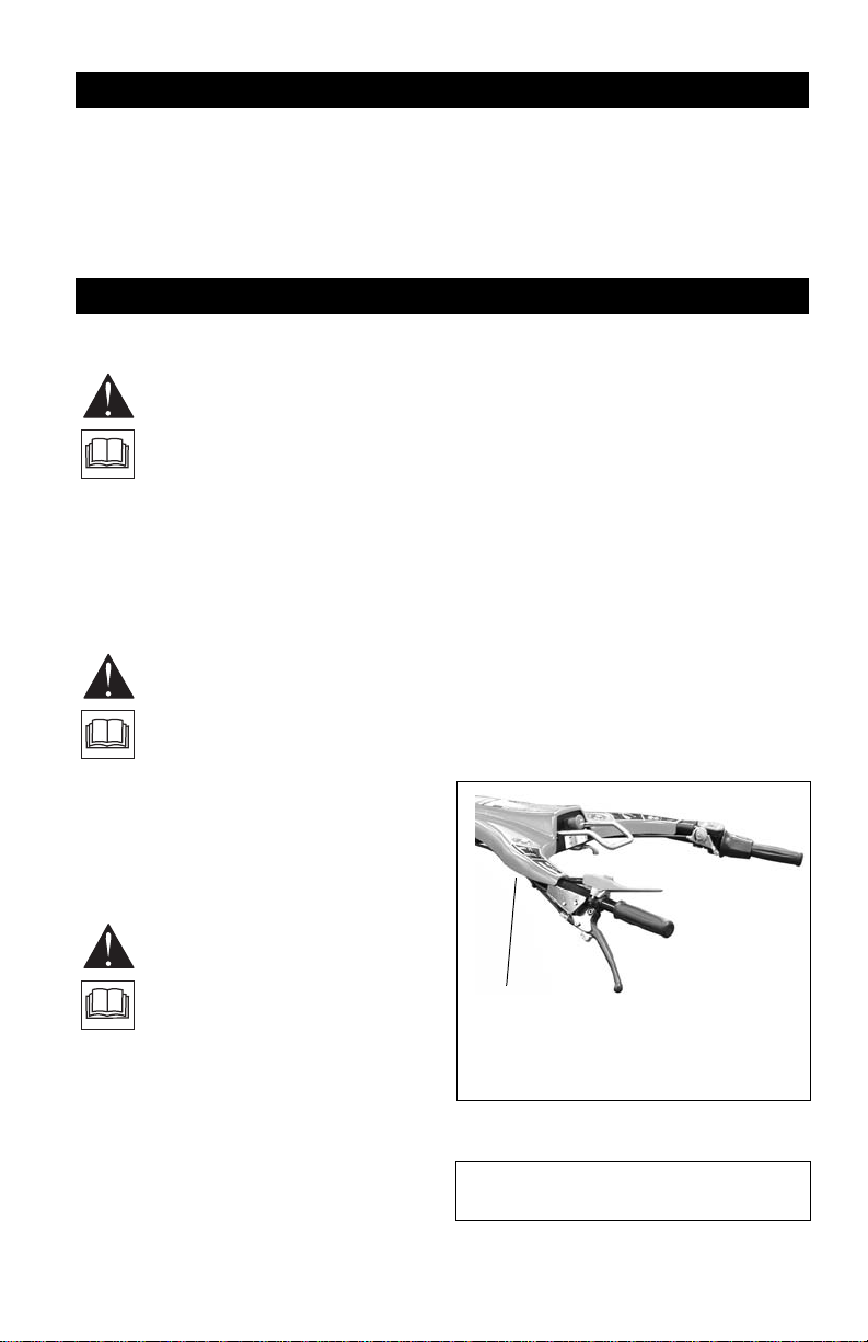
TABLE OF CONTENTS
Figure 1
Serial
Number
Label
Safety . . . . . . . . . . . . . . . . . . . . . . . . . . . 4
Assembly . . . . . . . . . . . . . . . . . . . . . . . . 8
Controls and Features. . . . . . . . . . . . . 10
Operation . . . . . . . . . . . . . . . . . . . . . . . 11
Maintenance Schedule . . . . . . . . . . . . 15
Storage . . . . . . . . . . . . . . . . . . . . . . . . . 17
INTRODUCTION
Trouble s hooting. . . . . . . . . . . . . . . . . . 18
Accessories . . . . . . . . . . . . . . . . . . . . . 18
Service Parts . . . . . . . . . . . . . . . . . . . . 18
Specifications . . . . . . . . . . . . . . . . . . . 19
Warranty. . . . . . . . . . . . . . . . . . . . . . . . 20
NON-ENGLISH MANUALS
Manuals in languages other than
English may be obtained from your
Dealer. Visit your dealer or
www.ariens.com for a list of
languages available for your
equipment.
Manuals printed in languages other
than English are also available as a
free download on our website:
http://www.ariens.com
MANUALES EN IDIOMAS
DIFERENTES DEL INGLES
Puede obtener manuales en
idiomas diferentes del inglés en su
distribuidor. Visite a su distribuidor
o vaya a www.ariens.com para
obtener una lista de idiomas
disponibles para su equipo.
También puede imprimir manuales
en idiomas diferentes del inglés
descargándolos gratuitamente de
nuestra página Web:
http://www.ariens.com
Manuels non anglais
Des manuels dans différentes
langues sont disponibles chez
votre revendeur. Rendez-vous
chez votre revendeur ou allez sur
le site www.ariens.com pour
consulter la liste des langues
disponibles pour votre équipement.
Les manuels imprimés dans des
langues différentes de l’anglais
sont également disponibles en
téléchargement gratuit sur notre
site Web :
http://www.ariens.com
THE MANUAL
Before operation of unit, carefully and
completely read your manuals. The contents
will provide you with an understanding of
safety instructions and controls during normal
operation and maintenance.
All reference to left, right, front, or rear are
given from operator standing in the operation
position and facing the direction of forward
travel.
SERVICE AND REPLACEMENT
PARTS
When ordering publications, replacement
parts, or making service inquiries, know the
Model and Serial numbers of your unit and
engine.
Numbers are located on the product
registration form in the literature package.
They are printed on a serial number label,
located on the frame of your unit (Figure 1).
• Record Unit Model and Serial numbers
here.
GB - 2

• Record Engine Model and Serial numbers
here.
PRODUCT REGISTRATION
The Gravely dealer must register the product
at the time of purchase. Registering the
product will help the company process
warranty claims or contact you with the latest
service information. All claims meeting
requirements during the limited warranty
period will be honored, whether or not the
product registration card is returned. Keep a
proof of purchase if you do not register your
unit.
Customer Note: If dealer does not register
your product, please fill out, sign and return
the product registration card to Gravely or go
to www.gravely.com on the internet.
UNAUTHORIZED REPLACEMENT
PARTS
Use only Gravely replacement parts. The
replacement of any part on this equipment
with anything other than a Gravely authorized
replacement part may adversely affect the
performance, durability, and safety of this unit
and may void the warranty. Gravely disclaims
liability for any claims or damages, whether
regarding warranty, property damage,
personal injury or death arising out of the use
of unauthorized replacement parts.
NOTE: To locate your nearest Gravely dealer,
go to www.gravely.com on the internet.
DISCLAIMER
Gravely reserves the right to discontinue,
change, and improve its products at any time
without public notice or obligation to the
purchaser. The descriptions and
specifications contained in this manual were
in effect at printing. Equipment described
within this manual may be optional. Some
illustrations may not be applicable to your
unit.
5. Explain recommended lubrication and
maintenance. Advise customer on
adjustments.
6. Instruct customer on controls and
operation of unit. Discuss and
emphasize the Safety Precautions. Give
customer Owner/Operator, Parts, and
Engine Manuals. Advise customer to
thoroughly read and understand them.
DEALER DELIVERY
Dealer should:
1. Check all controls for proper function.
2. Check the safety interlock system to
make sure that it is functioning properly.
See Safety Inte rlo ck Sy ste m on page 11.
3. Fill out Original Purchaser Registration
Card and return the card to Gravely.
4. Explain Gravely Limited Warranty Policy.
GB - 3
SAFETY
WARNING: This machine is
capable of amputating hands and
feet and throwing objects. Failure
to observe the safety instructions
in the manuals and on decals
could result in serious injury or
death.
Slopes are a major factor related
to loss-of-control and tip-over
accidents. Operation on all
slopes requires extra caution.
Tragic accidents can occur if the
operator is not alert to the
presence of children. Never
assume that children will remain
where you last saw them.
Gasoline is extremely flammable
and the vapors are explosive,
handle with care.
Disengage attachment, stop unit
and engine, engage parking
brake, and allow moving parts to
stop before leaving operator’s
position.
SAFETY ALERTS
Look for these symbols to
point out important safety
precautions. They mean:
Attention!
Personal Safety Is
Involved!
Become Alert!
Obey The Message!
The safety alert symbols
above and signal words below are used on
decals and in this manual.
Read and understand all safety messages.
CAUTION: POTENTIALLY
HAZARDOUS SITUATIO N! If not
avoided, MAY RESULT in minor or
moderate injury. It may also be used
to alert against unsafe practices.
NOTATIONS
NOTE: General reference information for
proper operation and maintenance practices.
IMPORTANT: Specific procedures or
information required to prevent damage to
unit or attachment.
PRACTICES AND LAWS
Practice usual and customary safe working
precautions, for the benefit of yourself and
others. Understand and follow all safety
messages. Be alert to unsafe conditions and
the possibility of minor, moderate, or serious
injury or death. Learn applicable rules and
laws in your area, including those that may
restrict the age of the operator.
REQUIRED OPERATOR
TRAINING
Original purchaser of this unit was instructed
by the seller on safe and proper operation. If
unit is to be used by someone other than
original purchaser; loaned, rented or sold,
ALWAYS provide this manual and any
needed safety training before operation.
SAFETY DECALS AND
LOCATIONS
ALW AYS replace missing or damaged Safety
Decals. Refer to Figure2 for Safety Decal
locations.
DANGER: IMMINENTLY
HAZARDOUS SITUATION! If not
avoided, WILL RESULT in death or
serious injury.
WARNING: POTENTIALLY
HAZARDOUS SITUATION! If not
avoided, COULD RESULT in death
or serious injury.
GB - 4
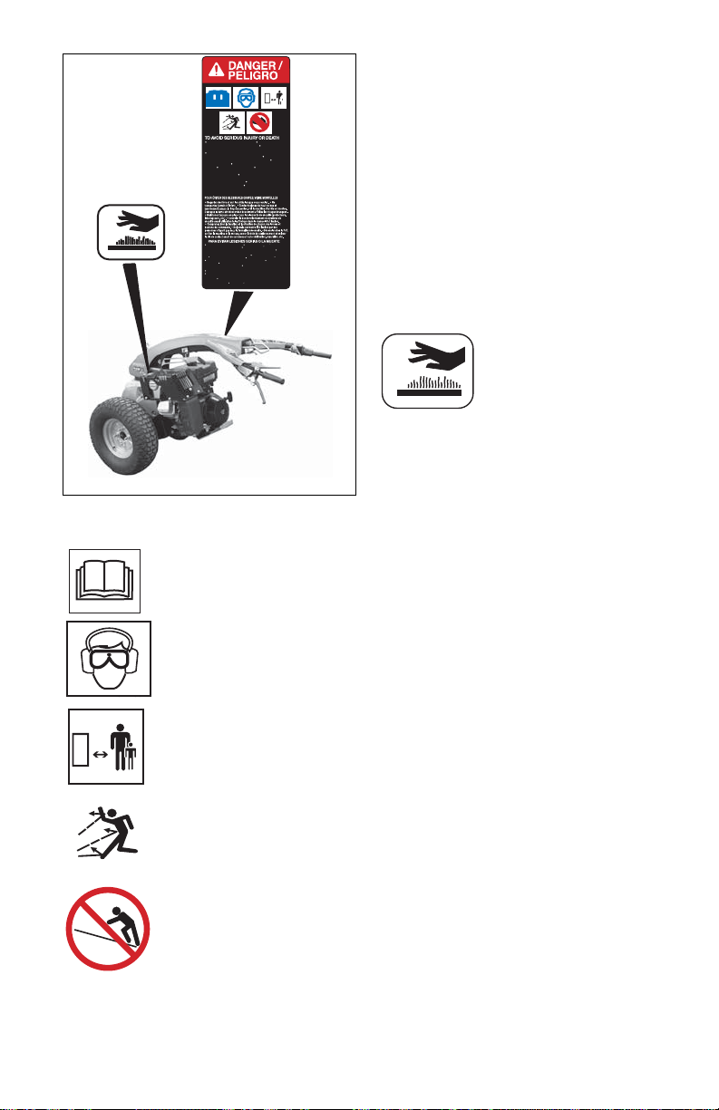
1. DANGER! TO AVOID SERIOUS
08677000
Read the operator's manual. Ware hearing and
eye protection while operating. Keep children
and others away from unit while operating.
Never direct discharge toward other people.
Thrown objects can cause injury. Look down
and behind before and while backing. Never
carry children. Go across slopes, not up and
down. Avoid sudden turns. Keep safety
devices (guards, shields, switches, ect.) in
place and working. Check interlock system per
manual before use. Understand location and
function of all controls. Never allow operation
by untrained persons. Discharge PTO, stop
unit and engine, set parking brake and remove
key before making any inspections, repairs, etc.
Leer el manual del operador. Usar protector de oido y ojo
cuando se opera la maquina. Mantener los ninos y a todos
alejados de la maquina cuando esta en funcionamiento. Nunca
dirija la descarge hacia otras pesonas, ya que los objetos
lanzados pueden provocar lesiones. Mirar hacia abajo y
atras antes y durante retroceso. Nunca monte a los ninos.
Suba y baje pendientes, no transversalmente. Evite cruzar de
improviso. Si la maquina se detiene subiendo cuesta, desactive
la cuchilla y baje lentamente. Mantenga artefactos de seguridad
(defensas, protectores, interruptores, etc.) en su lugar de trabajo.
Antes de usar verifique en el manual el sistema de engranar.
Tenga conocimiento de las funciones y localizacion de todos
los controles. Nunca permita que alguien no entrenado operar la
maquina. Desactivar la TDF/PTO, detener la unidad, apagar el
motor, accionar el freno de manoy quitar la llave antes de realizar
cualquier inspeccion, reparacion, etc.
Figure 2
1
2
OL1801
OS0731
INJURY OR DEATH
Read the operator’s manual.
Wear hearing and eye
protection while operating.
Keep children and others
away from unit while operating.
Never direct discharge
toward other people. Thrown
objects can cause injury.
Go across slopes, not up and
down.
• Look down and behind before while
backing.
• Never carry children.
• Go across slopes, not up and down.
• Avoid sudden turns.
• Keep safety devices (guards, shields,
switches, etc.) in place and working.
• Check interlock system per manual
before use. Understand location and
function of all controls.
• Never allow operation by untrained
persons.
• Disengage PTO, stop unit and engine
and set parking brake before making
any inspections, repairs, etc.
2. HOT SURFACES!
DO NOT touch parts which
are hot from operation.
ALWAY S allow p art s to cool.
SAFETY RULES
Read, understand and follow all safety
practices in Owner/Operator Manual before
beginning assembly. Failure to follow
instructions could result in personal injury
and/or damage to unit.
ALWAYS remove key (if equipped) and
disconnect wire from spark plug before
assembly. Unintentional engine start up can
cause death or serious injury.
Complete a walk around inspection of unit
and work area to understand:
• Work area
• Your unit
• All safety decals
ALWAYS check overhead and side
clearances carefully before operation.
ALWAYS be aware of traffic when operating
along streets or curbs.
Keep children and people away.
Keep children out of work area and under
watchful care of a responsible adult.
Keep area of operation clear of all toys, pets,
and debris. Thrown objects can cause injury.
Check for weak spots on docks, ramps or
floors. Avoid uneven work areas and rough
terrain.
Avoid slippery surfaces. ALWAYS be sure of
your footing.
Keep a firm hold on the handlebar. Walk,
NEVER run.
DO NOT operate on wet grass.
GB - 5

Dust, smoke, fog, etc. can reduce vision and
cause an accident. Operate unit only when
there is good visibility and light.
Read the entire Owner/Operator manual and
other training material. If the operator or the
mechanic cannot read the manual, it is the
owner’s responsibility to explain it to them.
Only the user can prevent and is responsible
for accidents or injuries occurring to
themselves, other people or property.
• Only trained adults may operate or
service unit
• Training includes actual operation
NEVER allow children to operate or play on
or near unit.
Be alert and shut off unit if children enter
area.
Never carry passengers.
NEVER operate unit after or during the use of
medication, drugs or alcohol. Safe operation
requires your complete and unimpaired
attention at all times.
NEVER allow anyone to operate this unit
when their alertness or coordination is
impaired.
Wear adequate safety gear, protective gloves
and footwear.
NEVER wear open sandals or canvas shoes
during operation.
Protect eyes, face and head from objects that
may be thrown from unit. Wear appropriate
hearing protection.
Sharp edges can cut. Moving parts can cut off
fingers or a hand. Wrap blade(s), wear sturdy
gloves and use extreme caution when
servicing. On multi-blade mowers, rotation of
one blade will cause all blades to rotate.
ALWAYS keep hands and feet away from all
rotating parts during operation. Rotating parts
can cut off body parts.
ALWAYS keep hands away from all pinch
points.
DO NOT touch unit parts which might be hot
from operation. Allow parts to cool before
attempting to maintain, adjust or service.
NEVER place your hands or any part of your
body or clothing inside or near any moving
part while unit is running.
DO NOT wear loose clothing or jewelry. Tie
back hair that may get caught in rotating
parts.
Keep children and people away from unit
during operation.
Fumes from engine exhaust can cause injury
or death.
DO NOT run engine in an enclosed area.
Always provide good ventilation.
When operating with attachments, thrown
objects can cause injury and property
damage. DO NOT point discharge at anyone
or discharge directly onto paved or gravel
surfaces. Always stand clear of the discharge
area when operating this unit.
Read, understand, and follow all instructions
in the manual and on the machine before
starting.
Understand:
• How to operate all controls
• The functions of all controls
• How to STOP in an Emergency
• Braking and steering characteristics
• Turning radius and clearance
ALWAYS keep protective structures, guards,
and panels in good repair, in place and
securely fastened.
NEVER modify or remove safety devices.
Check steering control operation frequently.
Adjust and service as required.
Safety Interlock System must function
properly. DO NOT operate unit if operator
presence control is damaged or disabled.
If you strike an object, or if equipment
vibrates abnormally, stop engine at once,
disengage PTO and wait for all moving parts
to stop. Check for any damage or loose parts.
Repair before restart.
Before starting engine: disengage PTO and
place unit in neutral.
DO NOT operate at too fast a rate. DO NOT
change engine governor settings or overspeed engine. Slow down and turn corners
slowly.
Disengage PTO when attachment is not in
use. ALWAYS turn off power to attachment
when travelling, crossing driveways, etc.
Avoid uneven and rough terrain. DO NOT
operate near drop-offs, ditches, or
embankments. Unit can suddenly turn over if
a wheel is over the edge of a cliff or ditch, or if
an edge caves in.
Use care when approaching blind corners,
shrubs, trees or other objects that may
obscure view.
ALWAYS disengage PTO, stop unit and
engine and allow moving parts to stop before
leaving operator’s position.
Never leave a running unit unattended.
ALWAYS shut off engine before leaving unit.
GB - 6

DO NOT operate in reverse unless absolutely
necessary. ALWAYS backup slowly. ALWAYS
look down and behind, before and while
backing.
DO NOT operate on steep slopes. DO NOT
operate on slopes of more than 5°. Operate
across the face of slopes, not up and down.
Turf conditions can affect the unit’s stability.
Keep all movement on slopes slow and
gradual. DO NOT make sudden changes in
speed or direction. Use a slow speed to avoid
stopping or shifting on slopes. Avoid starting
or stopping on a slope.
DO NOT park unit on a slope unless
absolutely necessary. When parking on a
slope always chock or block wheels.
Use extra care when loading or unloading
unit onto trailer or truck.
Secure unit chassis to transport vehicle.
NEVER secure from rods or linkages that
could be damaged.
DO NOT transport machine while engine is
running.
Keep unit free of grass, leaves, or other
debris. Clean up oil or fuel spills.
This product is equipped with an internal
combustion engine. DO NOT use on or near
any unimproved, forest covered or brush
covered land unless the exhaust system is
equipped with a spark arrester meeting
applicable local, state or federal laws. A spark
arrester, if used, must be maintained in
effective working order by the operator.
Fuel is highly flammable and its vapors are
explosive. Handle with care. Use an
approved fuel container.
No smoking, No sparks, No flames. ALWA YS
allow engine to cool before servicing.
NEVER fill fuel tank when engine is running
or hot from operation.
NEVER fill or drain fuel tank indoors.
Replace fuel cap securely and clean up
spilled fuel.
Never fill containers inside a vehicle or on a
truck or trailer bed with a plastic liner. Always
place containers on the ground away from
your vehicle before filling.
When practical, remove gas-powered
equipment from the truck or trailer and refuel
it on the ground. If this is not possible, then
refuel such equipment on a trailer with a
portable container, rather than from a
gasoline dispenser nozzle.
Keep the nozzle in contact with the rim of the
fuel tank or container opening at all times until
fueling is complete. Do not use a nozzle lockopen device.
If fuel is spilled on clothing, change clothing
immediately.
NEVER store fuel inside where there is an
open flame, such as a water heater.
HYDRAULIC FLUID can result in severe
burns. Fluid in hydraulic system can
penetrate skin and result in serious injury or
death.
• Be sure to stop the engine before
doing any work on hydraulic parts.
• Keep body and hands away from pin
holes or nozzles which expel hydraulic
fluid when under pressure. Use paper
or cardboard, not hands, to search for
leaks.
• Ensure all hydraulic fluid connections
are tight and all hydraulic hoses and
lines are in good condition before
applying pressure to system.
• FOREIGN FLUID INJECTED INTO
BODY can result in gangrene. Fluid
must be surgically removed within a
few hours by a doctor familiar with this
form of injury.
Before making any inspections, repairs, etc.:
disengage PTO, stop unit and engine and
allow moving parts to stop.
Allow hot parts to cool.
ALW A YS block wheels, engage parking brake
and know all jack stands are strong, secure
and will hold weight of unit during
maintenance.
An extension spring, when extended, stores
energy and can be dangerous. Always use
tools specifically designed for installing or
removing an extension spring. Always
compress or extend springs slowly.
ALWAYS maintain unit in safe operating
condition. Damaged or worn out muffler can
cause fire or explosion.
Keep hardware tight.
Maintain or replace safety and instruction
labels, as necessary.
For unit storage or extended storage:
• NEVER store with fuel in fuel tank
inside a building where any ignition
sources are present.
• Allow engine to cool completely.
Use only attachments or accessories
designed for your unit and that can be used
safely on your terrain.
Check attachment components frequently. If
worn or damaged, replace with
manufacturer’s recommended parts.
GB - 7

To reduce fire hazard and overheating, keep
Figure 3
Install wheel as shown.
Make sure the recess for
the lug nuts faces out and
the rim does not grind
against the unit frame.
Lug nuts
Lug nuts
equipment free of grass, leaves, debris or
excessive lubricants.
Use extra care with grass catchers and other
attachments. These can change the stability
of the unit. Use only approved hitch points.
ASSEMBLY
WARNING: AV O I D INJURY.
Read and understand entire
Safety section before proceeding.
UNIT ASSEMBLY
Package Contents:
Unit, Tires, and Literature Pack
Unpack Unit
Remove unit and all other components from
shipping container. Open bypass valve (see
Hydraulic Bypass Valve on page 13). Push
unit from container onto a level surface.
Close bypass valve.
Install Tires
Safely raise and support the unit. Remove the
hardware from the wheel mounts. Save the
lug nuts.
Install the left and right wheels with the lug
nuts supplied on the unit. Tighten the lug nuts
to 80 lbf-ft (108 N•m) (Figure 3).
IMPORTANT: The wheels are designed to be
installed one way. Installing the wheels
incorrectly will grind the rims against the unit
frame, damaging the frame and the wheel
rim. Install the wheel so the recess for the lug
nuts faces out.
ALWAYS be aware of attachments when
turning. ALW AYS allow adequate clearance
between attachments, personnel, and other
objects.
NOTE: Gravely does not recommend or
approve of the use of a sulky or other
stand-on or sit-on device for transporting
the operator on this unit. Use of such
devices may render the machine unsafe
and will void the warranty.
GB - 8

Check Tire Pressure
Check the tire pressure and, if necessary,
inflate tires to the pressure listed on the tire
sidewall.
CAUTION: Avoid injury! Explosive
separation of tire and rim parts is
possible when they are serviced
incorrectly:
• Do not attempt to mount a tire
without the proper equipment
and experience to perform
the job.
• Do not inflate the tires above
the recommended pressure.
• Do not weld or heat a wheel
and tire assembly. Heat can
cause an increase in air
pressure resulting in an
explosion. Welding can
structurally weaken or deform
the wheel.
• Do not stand in front or over
the tire assembly when
inflating. Use a clip-on chuck
and extension hose long
enough to allow you to stand
to one side.
Check Engine Oil
Refer to Engine Manual.
Fill Fuel Tank
See FILLING FUEL TANK on page 14.
Hardware
Check for loose hardware.
Check Safety Interlock System
WARNING: Safety inter lo c k
system failure and improper
operation of unit can result in death
or serious injury. Test this system
each time unit is operated. If this
system does not function as
described, do not operate until
repairs are made.
See Safety Interlock System on page 11.
Check Function of All Controls
Ensure unit runs and performs properly.
WARNING: FAILURE OF
CONTROLS could result in death
or serious injury.
GB - 9

CONTROLS AND FEATURES
1
2
3
4
11
5
6
7
8
9
10
12
Figure 4
13
14
1. PTO Switch
2. Forward / Reverse Control
3. Throttle Control Lever
4. Differential Lock
5. Operator Presence Lever
6. Parking Brake / Clutch Lever
7. Fuel Shut-Off Valve
8. Recoil Starter Handle
9. Choke Control
10. Handlebar Height Adjuster
11. Hydraulic Bypass Valve
12. Handlebar
13. PTO Shaft
14. Attachment Locking Pin
GB - 10

OPERATION
WARNING: AVOID INJURY. Read
and understand entire Safety
section before proceeding.
CONTROLS AND FEATURES
See Figure 4 for Controls and Features
locations.
Safety Interlock System
WARNING: Safety inter lo c k
system failure and improper
operation of unit can result in
death or serious injury. Test this
system each time the unit is
operated. If this system does not
function as described, do not
operate until repairs are made.
Perform the following tests to ensure the
safety interlock system is working properly. If
the unit does not perform as stated, contact
your Gravely dealer for repairs.
IMPORTANT: With the parking brake/ clutch
disengaged, the engine must not start and
the engine must shut off if the operator
releases the operator presence lever.
DANGER: The engine can be
started with the forward / reverse
control out of the neutral position
when the parking brake / clutch is
engaged. Releasing the parking
brake/ clutch while holding down
the operator presence lever will
start the unit driving forward.
MAKE SURE the forward / reverse
control is in the neutral position
prior to starting the engine.
Test Operator
Presence
Lever
STARTING INTERLOCK
1 Off On or
2 Off Off Dis-
OPERATING INTERLOCK (ENGINE ON)
3 Off Off Engaged On
4 On On Dis-
5 Off On or
PTO Parking
Brake /
Clutch
Engaged Starts
Off
engaged
engaged
Dis-
Off
engaged
Engine
Doesn’t
Start
On
Shuts
Off
Operator Presence Lever
IMPORTANT: With the parking brake/ clutch
disengaged, the engine must not start and
the engine must shut off if the operator
releases the operator presence lever.
This safety feature ensures that the operator
presence lever must be depressed to operate
the unit and engage the PTO when the
parking brake/ clutch is disengaged.
GB - 11

Forward / Reverse Control (Figure 5)
A
B
Neutral
Position
Figure 5
Forward /
Reverse
Control
OF1680
2
1
2
1
The forward / reverse control controls forward
and reverse speed. In addition, the lever will
stop the unit.
A. For reverse travel, turn forward /
reverse control counterclockwise.
B. For forward travel, turn forward /
reverse control clockwise.
Choke Control
Choke Closed: Used to start a cold engine.
Choke Open: Used for normal operation.
NOTE: Gradually open choke after the
engine starts.
Throttle Lever
Changes the
engine speed.
Fast (1) –
Increases engine
speed.
Slow (2) –
Decreases engine
speed.
Power Take Off (PTO) Switch
Power take-off (PTO)
switch engages and
disengages the PTO.
Pull the power takeoff (PTO) switch to
On position to
engage (2).
Push the power
take-off (PTO) switch
to Off position to
disengage (1).
IMPORTANT: The engine will start if the PTO
switch is in the On position. The PTO switch
must be reset prior to using the PTO. To
reset, push in the PTO switch and then pull
the PTO switch to engage the PTO.
Parking Brake / Clutch Lever
(Figure 6)
1. Pull parking brake / clutch lever up.
2. Engage locking latch.
NOTE: To release the parking brake / clutch
lever, pull up on the lever and the locking
latch will release.
IMPORTANT: Engaging the parking brake /
clutch lever when the PTO is on will
disengage the PTO.
GB - 12

Differential Lock
Figure 6
Locking
Latch
Parking Brake /
Clutch Lever
Locks the differential so both wheels are
locked together to increase traction.
Push in the differential lock to lock the
wheels. Pull out the differential lock to unlock
the wheels and to aid in turning the machine.
NOTE: The differential lock can be engaged,
and disengaged, while the machine is moving
or when stopped.
Handlebar Height Adjuster
NOTE: Do not adjust the handlebar height
while driving the unit.
Pull out the handlebar height adjuster and
raise or lower the handlebar to a comfortable
height and then push in the adjuster. Move
the handlebar up or down to lock the
handlebar into position.
Attachment Locking Pin
Open the locking pin to install or remove
attachments. Close the locking pin to secure
the attachment to the unit.
IMPORTANT: MAKE SURE the locking pin is
completely seated prior to engaging the PTO.
Installing Attachments
WARNING: The engine must off
and the parking brake set, prior to
installing attachments.
NOTE: Some attachment s will require the two
wheel tractor attachment adaptor kit
78510700.
1. Clean dirt and debris from the
attachment and PTO socket.
2. Grease the splines of the PTO shaft and
the PTO socket.
3. Open the locking pin.
4. Push the attachment into the PTO
socket.
5. Close the locking pin to secure the
attachment.
IMPORTANT: MAKE SURE the locking pin is
completely seated prior to engaging the PTO.
Removing Attachments
WARNING: The engine must be
off and the parking brake set, prior
to removing attachments.
1. Open the locking pin.
2. Remove the attachment.
Hydraulic Bypass Valve
WARNING: DO NOT disengage
the transmission on a slope.
The bypass valve allows the hydraulic
transmission to freewheel or to drive. Push
the bypass valve down to engage the
transmission. Pull the bypass valve up to
disengage the transmission.
GB - 13

4. Check Tire Pressure
STOPPING IN AN EMERGENCY
The unit can be stopped immediately at any
time by releasing the operator presence
lever.
STARTING AND SHUT OFF
IMPORTANT: Towing the unit will damage the
hydraulic transmission.
FILLING FUEL TANK
WARNING: A VOID INJURY . Read
and understand entire Safety
section before proceeding.
Add fuel to fuel tank as needed. See your
Engine Manual for correct type and grade of
fuel.
To add fuel to the fuel tank:
1. Place unit in an open or well-ventilated
open area.
2. Stop the engine.
3. Clean the fuel cap and the area around
the fuel cap to prevent dirt from entering
the fuel tank. Remove the cap from the
fuel tank.
4. Fill the fuel tank to within 1 in. (25 mm)
below bottom of filler neck.
5. Replace fuel cap and tighten.
6. Clean up any spilled fuel.
PRE-START
CAUTION: Make sure a l l
hardware is tight, all safety
devices are in place and all
adjustments are made correctly.
1. Check Safety Interlock System
If this system does not function as described
do not operate until repairs are made.
2. Check Air Cleaner
Check air filter for dirt. Clean as required.
Follow Engine Manual Maintenance
Schedule.
3. Check Engine Fuel and Crankcase
Oil
Check and add fuel if required. Check that
engine crankcase oil is full. Follow Engine
Manual Maintenance Schedule.
CAUTION: Read entire
Owner/Operator Manual and
Engine Manual first. DO NOT
attempt to start engine at this time.
NOTE: If engine will not start, see
TROUBLESHOOTING on page 18 or refer to
Engine Manual.
IMPORTANT: The engine will start if the PTO
switch is in the On position. The PTO switch
must be reset prior to using the PTO. To
reset, push in the PTO switch and then pull
the PTO switch to engage the PTO.
IMPORTANT: With the parking brake / clutch
disengaged, the engine must not start and
the engine must shut off if the operator
releases the operator presence lever.
DANGER: The engine can be
started with the forward / reverse
control out of the neutral position
when the parking brake / clutch is
engaged. Releasing the parking
brake / clutch while holding down
the operator presence lever will
start the unit driving forward.
MAKE SURE the forward / reverse
control is in the neutral position
prior to starting the engine.
NOTE: Parking brake / clutch must be
engaged to start unit.
To start:
1. If the engine is cold, move the choke
control to the closed position. If the
engine is warm or hot, do not use choke.
2. Move the throttle to 3/4 Fast position.
See Engine Manual for detailed
instructions.
3. Engage the parking brake / clutch.
4. Pull recoil starter handle.
5. As soon as the engine starts move the
choke control to the open position from
the choke position. Wait until the engine
is running smoothly before operation.
To shut off:
1. Bring the forward / reverse control to
neutral. Disengage the PTO.
2. Move the throttle lever to the Slow
position.
GB - 14

3. With the parking brake / clutch
disengaged, release the operator
presence lever.
NOTE: Releasing the operator presence
lever will not shut off the unit if the parking
brake / clutch is engaged.
4. After engine is stopped reset the parking
brake / clutch to keep the unit from
moving.
MAINTENANCE SCHEDULE
WARNING: AVOID INJURY. Read
and understand entire Safety
section before proceeding.
Gravely Dealers will provide any servi ce whi ch
may b e required t o keep your unit operating at
peak efficiency. Should engine service be
required, it can be obtained from a Gravely
Dealer or the engine manufacturer’s
authorized service center.
WARNING: AVOID INJURY . Read
and understand entire Safety
section before proceeding.
CAUTION: HOT SURF ACES may
result in injury. DO NOT touch
engine or drive parts which are hot
from operation. Allow parts to cool
before servicing.
TRANSPORTING UNIT
ALWAYS shut off engine and set parking
brake / clutch when transporting unit on a
truck or trailer. Tie unit down securely. Do not
tie down by linkages, guards, cables or other
parts that may be damaged.
Proper maintenance can prolong the life of
unit. The following charts show the
recommended service schedule. More
frequent service may be required due to
working conditions (heavy loads, high
ambient temperatures, dusty conditions, or
airborne debris).
See the maintenance instructions in the
Engine Manual for additional information.
GB - 15

Interval Task Action
PTO Shaft and
PTO Socket
Grease
Zerk
Each Use
Weekly or
As
Check Safety Interlock
System
not function as described, do not operate until repairs
are made. See Safety Interlock System on page 11.
Check Parking Brake /
Clutch
Check Tires See SPECIFICATIONS on page 19 for correct tire
Clean Unit Clean unit of dirt and debris. Do not use solvents, hard
Follow Engine
Maintenance Schedule
Lubricate PTO shaft
and PTO socket.
Engage parking brake / clutch. Push unit. If unit rolls,
see your Gravely Dealer.
pressure.
cleaners, or abrasives.
NOTE: Protect painted surfaces with automotive type
wax.
Perform scheduled engine maintenance. Refer to
Engine Manual for detailed instructions.
Needed
WARNING: Safety interlock system failure
and improper operation of unit can result in
death or serious injury. Test this system each
time the unit is operated. If this system does
Monthly
250 Hours
Check transmission oil
level.
Replace hydraulic oil
filter.
Check transmission oil level and add SAE 20W/50 oil
as needed. Do not overfill. See Checking Hydraulic Oil
Level on page 17.
Replace hydraulic oil filter. See your Gravely Dealer.
GB - 16

HYDRAULIC OIL SYSTEM
Figure 7
Oil Filter
Oil Fill Plug
WARNING: HYDRAULIC FLUID
can result in severe burns. Fluid in
hydraulic system can penetrate
skin and result in serious injury or
death.
Be sure to stop the engine before
doing any work on hydraulic parts.
Keep body and hands away from
pin holes or nozzles which expel
hydraulic fluid when under
pressure. Use paper or
cardboard, not hands, to search
for leaks.
Ensure all hydraulic fluid
connections are tight and all
hydraulic hoses and lines are in
good condition before applying
pressure to system.
FOREIGN FLUID INJECTED
INTO BODY can result in
gangrene. Fluid must be surgically
removed within a few hours by a
doctor familiar with this form of
injury.
STORAGE
WARNING: AVOID INJURY.
Read and understand entire
Safety section before proceeding.
SHORT TERM
NEVER spray unit with high pressure water
or store unit outdoors.
Inspect unit for visible signs of wear,
breakage or damage.
Keep all nuts, bolts and screws properly
tightened and know unit is in safe working
condition.
Store unit in a cool, dry protected area.
LONG TERM
Clean unit thoroughly with mild soap and low
pressure water and lubricate (See on
page 17 in Maintenance). Touch up all
scratched painted surfaces.
Remove weight from wheels by putting
blocks under frame or axle.
Checking Hydraulic Oil Level
1. Start the unit and run it to operating
temperature (about 10 minutes).
2. Shut off engine. Engage parking brake.
3. Remove the left side panel. (Figure 7)
4. Remove any dirt that may be around the
oil fill plug and remove plug.
5. Check hydraulic oil level. The oil level
should be at or near the top.
6. Add SAE 20W/50 oil as needed. Do not
overfill.
7. Install oil fill plug.
8. Install the left side panel.
Fuel System
Gasoline left in the fuel system for extended
periods without a stabilizer will deteriorate,
resulting in gum deposits in the system.
These deposits can damage the carburetor
and the fuel hoses, filter and tank. Prevent
deposits from forming in the fuel system
during storage by adding a quality fuel
stabilizer to the fuel. Follow the
recommended mix ratio found on the fuel
stabilizer container.
To treat the fuel system for storage:
1. Add fuel stabilizer (Ariens part number
00592900) according to manufacturers’s
instructions.
2. Run engine for at least 10 minutes after
adding stabilizer to allow it to reach the
carburetor.
NEVER store the engine with fuel in the fuel
tank inside of a building with potential
sources of ignition.
To Take the Unit Out of Storage
1. Refer to the engine service manual to
prepare the engine for service.
2. Put fresh, clean fuel in the fuel tank.
3. Begin the maintenance schedule.
GB - 17

TROUBLESHOOTING
PROBLEM PROBABLE CAUSE CORRECTION
Engine does not
start.
PTO does not
engage or shuts
off.
Unit does not
drive.
1. Operator presence lever not
engaged.
2. Fuel tank empty.
3. Faulty spark plug.
4. Air cleaner is plugged or dirty.
5. Fuel filter is dirty.
6. Faulty engine.
1. Operator presence lever not
depressed.
2. Parking brake / clutch
engaged.
3. PTO switch was pulled out
when the engine was started.
1. Parking brake / clutch
engaged.
2. Transmission bypass levers
open.
3. Hydraulic oil level low.
4. Faulty hydraulic drive system.
1. Engage the operator
presence lever.
2. Fill fuel tank (see FILLING
FUEL TANK on page 14).
3. Replace spark plug. Refer to
Engine Manual.
4. Clean or replace air cleaner.
Refer to Engine Manual.
5. Clean or replace fuel filter.
Refer to Engine Manual.
6. Refer to Engine Manual or
see your Gravely Dealer.
1. Depress operator presence
lever.
2. Release parking brake /
clutch lever.
3. Reset PTO by pushing in the
PTO switch and then pulling
out on the switch.
1. Disengage parking brake /
clutch.
2. Close transmission bypass
levers (see Hydraulic Bypass
Valve on page 13).
3. Fill hydraulic system. See
Checking Hydraulic Oil Level
on page 17.
4. See your Gravely dealer.
ACCESSORIES
Part No. Description
78511600 Electric Start Kit
88501500 44-Inch Power Brush
83300700 32-Inch Snow Throw
88500100 30-Inch Mower Deck
88500500 40-Inch Mower Deck
78510700 Two Wheel Tractor Attachment
Adaptor
88501400 48-Inch Blade
78511700 Car Pusher
00592900 Fuel Stabilizer 4 oz.
SERVICE PARTS
Part No. Qty Description
08690800 1 Air Filter
08690100 1 Spark Plug
08690600 1 Hydraulic Oil Filter
GB - 18

SPECIFICATIONS
Model Number 985403
Model Rapid M
Engine
Engine Briggs & Stratton V anguard
Engine Model Number 245437
Engine Power – hp (kW) at Maximum
RPM
Max RPM 3600
Cooling Capacity Air Cooled
Speed
Forward Maximum – mph (km/h) 4 (6.5)
Reverse Maximum – mph (km/h) 2 (3)
Brakes Mechanical Parking Brake
Electrical
Starter Recoil
Power Take-Off Electric PTO Clutch
Fuel
Fuel Type Refer to Engine Manual
Transmission
Type Hydrostatic Drive
Oil SAE 20W/50
Tires
Tire Pressure Inflate to pressure listed on tire sidewall.
Size and Weight
Length – in. (cm) 61-1/2 (156)
Width – in. (cm) 32-1/4 (82)
Height – in. (cm) 35.4 – 46-1/2 (90 – 118)
Weight – lbs (kg) 340 (154)
13 (9.5)
GB - 19

Two-Year Limited Lawn and
Garden Commercial Warranty
Ariens Company (Ariens) warrants to the original purchaser that Ariens and Gravely brand products
manufactured by Ariens, designated or labeled commercial products by Ariens, and sold after December 31,
2007 will be free from defects in material and workmanship for a period of two years after the date of
purchase or 1000 hours of use, whichever comes first. An authorized Ariens dealer (Ariens brand products)
or Gravely dealer (Gravely brand products) will repair any defect in material or workmanship, and repair or
replace any defective part, subject to the conditions, limitations and exclusions set forth herein. Such repair
or replacement will be free of charge to the original purchaser (labor and parts), except as noted below.
Limited Lifetime Warranty on Mower Deck Shell
The deck shell is warranted to the original purchaser against any defect in material or workmanship
for as long as the original purchaser owns the product. Any defect in material or workmanship of the
deck shell will be repaired free of charge (parts and labor) to the original purchaser for two years or
1000 hours of use, whichever comes first. After two years or 1000 hours of use, the parts required to
repair a defect in material or workmanship of the deck shell, not the labor, will be provided free of
charge for as long as the original p urchaser owns the product.
Limited Lifetime W a r r a nty on Main Frame
The main frame is warranted to the original purchaser against any defect in material or workmanship
for as long as the original purchaser owns the product. Any defect in material or workmanship of the
main frame will be repaired free of charge (parts and labor) to the original purchaser for two years or
1000 hours of use, whichever comes first. After two years or 1000 hours of use, the parts required to
repair a defect in material or workmanship of the main frame, not the labor, will be provided free of
charge for as long as the original p urchaser owns the product.
Three-Year Limited Warranty on Deck Spindles
Mower deck spindles are warranted to the original purc hase r for three years from the date of purchase. Any defect in material or workmanship of the mower deck spindles will be repaired free of
charge (parts and labor) to the original purchaser for two years after the date of purchase. After two
years, the parts required to repair a defect in material or workmanship of the deck spindles, not the
labor, will be provided free of charge.
One-Year Limited Warranty on 21-inch Walk-Behind Lawn Mowers
21-inch walk-behind lawn mowers labeled or designated by Ariens as a Professional/Commercial product put to any business use, agricultural, commercial, or industrial, are warranted to the original pur-
chaser to be free from defects in material and workmanship for a period of one year after the date of
purchase.
90-Day Limited Warranty on Service Parts and Accessories
Genuine Ariens or Gravely brand service parts and accessories are warranted to be free from defects
in material and workmanship for a period of 90 days after the date of purchase. An authorized Ariens or
Gravely dealer will repair or replace any such part or accessory free of charge, except for labor, during
that period.
If any product is rented or leased, then the duration of these warranties shall be 90 days after the date of
purchase.
Exceptions, Limitations, Exclusions
Customer Responsibiliti e s
Register the product immediately at the time of sale. If the dealer does not register the product, the
customer must complete the product registration card in the literature package and return it to the Ariens
Company, or register the unit online at www.ariens.com or www.gravely.com.
To obtain warranty service, the original purchaser must:
• Perform the maintenance and minor adjustments explained in the owner’s manual.
• Promptly notify Ariens or an authorized Ariens or Gravely service representative of the need for
warranty service.
• Transport the product to and from the place of warranty service.
• Have the warranty service performed by an authorized Ariens or Gravely service representative.
ARIENS COMPANY
GRAVELY® | STENS® | LOCKE® | NATIONAL® | BYNORM® | EVERRIDE® | GREAT DANE®
Com_Lawn_2008
20

To find an Ariens or Gravely authorized service representative, contact Ariens at:
655 W. Ryan Street
Brillion, WI 54110
(920) 756 - 2141
www.ariens.com
www.gravely.com
Limitations
• Batteries are warranted only for a period of 12 months after date of purchase, on a prorated basis. For
the first 90 days of the warranty period, a defective battery will be replaced free of charge. If the
applicable warranty period is more than 90 days, Ariens will cover the prorated cost of any defective
battery, for up to 12 months after the date of purchase.
Exclusions – Items Not Covered by This Warranty
• Engines and engine accessories are covered only by the engine manufacturer’s warranty and are not
covered by this warranty.
• Eye-Q™ and Scan-Mate™ units are covered by their own warranty and are not covered by this
warranty.
• Parts that are not genuine Ariens or Gravely service parts are not covered by this warranty.
• The following maintenance, service and replacement items are not covered by this warranty unless
they are noted in the Limitations section above: lubricants, spark plugs, oil, oil filters, air filters, fuel
filters, brake linings, brake arms, shoes, runners, scraper blades, shear bolts, mower blades, mower
vanes, headlights, light bulbs, knives, cutters.
• Mufflers, belts and tires on Ariens and Gravely commercial lawn and garden products are not covered
by this warranty.
• Any misuse, alteration, improper assembly, improper adjustment, neglect, or accident which requires
repair is not covered by this warranty.
• This warranty applies only to products purchased in the United States (including Puerto Rico) and
Canada. In all other countries, contact pl ace of purchase for warranty information.
Disclaimer
Ariens may from time to time change the design of its products. Nothing contained in this warranty shall be
construed as obligating Ariens to incorporate such design changes into previously manufactured products,
nor shall such changes be construed as an admission that previous designs were defective.
LIMITATION OF REMEDY AND DAMAGES
Ariens Company’s liability under this warranty, and under any implied warranty that may exist, is limited to
repair of any defect in workmanship, and repair or replacement of any defective part. Ariens shall not be
liable for incidental, special, or consequential damages (including lost profits). Some states do not allow the
exclusion of incidental or consequential damages, so the above limitation or exclusion may not apply to you.
DISCLAIMER OF FURTHER WARRANTY
Ariens Company makes no warranty, express or implied, other than what is expressly made in this
warranty. If the law of your state provides that an implied warranty of merchantability, or an implied
warranty of fitness for particular purpose, or any other implied warranty, applies to Ariens Company,
then any such implied warranty is limited to the duration of this warranty. Some states do not allow
limitations on how long an implied warranty lasts, so the above limitation may not apply to you.
This warranty gives you specific legal rights, and you may also have other rights which
ARIENS COMPANY
GRAVELY® | STENS® | LOCKE® | NATIONAL® | BYNORM® | EVERRIDE® | GREAT DANE®
vary from state to state.
Com_Lawn_2008
21

GRAVELY
655 West Ryan Street
Brillion, WI 54110-1072
920-756-2141
Fax 920-756-2407
www.gravely.com
 Loading...