


Pro-Turn
400 Diesel
Operator’s Manual
Manuel du I’utilisateur
992236 – Pro-Turn 460 Diesel
992240 – Pro-Turn 472 Diesel
™
Models
(SN 050,000 +)
(SN 050,000 +)
ENGLISH
FRANÇAIS
04887100 • 9/15
Printed in USA
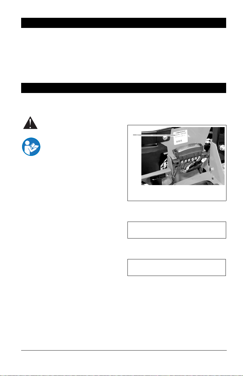
TABLE OF CONTENTS
Figure 1
1
1. Serial Number Label
SAFETY. . . . . . . . . . . . . . . . . . . . . . . . . . 4
ASSEMBLY. . . . . . . . . . . . . . . . . . . . . . 13
CONTROLS AND FEATURES . . . . . . . 15
OPERATION . . . . . . . . . . . . . . . . . . . . . 16
MAINTENANCE SCHEDULE . . . . . . . . 24
SERVICE AND ADJUSTMENTS . . . . . 27
STORAGE. . . . . . . . . . . . . . . . . . . . . . . 44
TROUBLESHOOTING . . . . . . . . . . . . . 45
ACCESSORIES. . . . . . . . . . . . . . . . . . . 46
SERVICE PARTS . . . . . . . . . . . . . . . . . 46
SPECIFICATIONS. . . . . . . . . . . . . . . . . 47
WARRANTY . . . . . . . . . . . . . . . . . . . . . 48
INTRODUCTION
MANUALES EN IDIOMAS DIFERENTES DEL INGLES
Puede obtener manuales en
idiomas diferentes del inglés en su
distribuidor. Visite a su distribuidor
o vaya a www.ariens.com para
obtener una lista de idiomas
disponibles para su equipo.
T ambién puede imprimir manuales
en idiomas diferentes del inglés
descargándolos gratuitamente de
nuestra página Web:
http://www.gravely.com
THE MANUAL
Before operation of unit, carefully and
completely read your manuals. The contents
will provide you with an understanding of
safety instructions and controls during normal
operation and maintenance.
All reference to left, right, front, or rear are
given from operator sitting in the operation
position and facing the direction of forward
travel.
ENGINE MANUAL
The engine on this unit is covered by a
separate manual specific to the engine. This
manual is included in the literature package
that shipped with the unit. Refer to this
manual for engine service recommendations.
If the engine manual is not available, contact
the engine manufacturer for a replacement
manual.
SERVICE AND REPLACEMENT PARTS
When ordering publications, replacement
parts, or making service inquiries, know the
model and serial numbers of your unit and
engine.
Numbers are located on the product
registration form in the literature package.
They are printed on a serial number label,
located on the frame of your unit (Figure 1).
• Record Unit Model and Serial
numbers here.
• Record Engine Model and Serial
numbers here.
PRODUCT REGISTRATION
The Gravely dealer must register the product
at the time of purchase. Registering the
product will help the company process
warranty claims or contact you with the latest
service information. All claims meeting
requirements during the limited warranty
period will be honored, whether or not the
product registration card is returned. Keep a
proof of purchase if you do not register your
unit.
EN - 2

Customer Note: If the Dealer does not
register your product, please fill out, sign and
return the product registration card to Gravely
or go to www.gravely.com on the Internet.
UNAUTHORIZED REPLACEMENT PARTS
Use only Gravely replacement parts. The
replacement of any part on this equipment
with anything other than a Gravely authorized
replacement part may adversely affect the
performance, durability, and safety of this unit
and may void the warranty. Gravely disclaims
liability for any claims or damages, whether
regarding warranty, property damage,
personal injury or death arising out of the use
of unauthorized replacement parts.
NOTE: To locate your nearest Gravely
Dealer, go to www.gravely.com.
DISCLAIMER
Gravely reserves the right to discontinue,
change, and improve its products at any time
without public notice or obligation to the
purchaser. The descriptions and
specifications contained in this manual were
in effect at printing. Equipment described
within this manual may be optional. Some
illustrations may not be applicable to your
unit.
DEALER DELIVERY
Dealer should:
1. Test parking brake after unit is
assembled to be sure adjustment has
not been disturbed in shipment (See
Parking Brake Interlock System on
page 17). Wheel brakes are properly
adjusted at factory.
2. Check the safety inte rlock sys tem to
make sure that it is functioning properly.
With operator on seat, unit must not start
unless steering levers are in neutral and
power takeoff (PTO) is disengaged (Off).
Engine must stop if operator lifts from
seat when steering levers are in any
drive position or PTO is engaged (On).
See Safety Interlock System on
page 16.
3. Fill out Original Purchaser Registration
Card and return the card to Gravely.
4. Explain Limited Warranty Policy.
5. Explain recommended lubrication and
maintenance. Advise customer on
adjustments. Instruct customer on
controls and operation of unit. Discuss
and emphasize the Safety Precautions.
Give customer this Owner/Operator and
the engine manual. Advise customer to
thoroughly read and understand them.
Customer Note: Your Dealer has been
provided complete set-up and preparation
instructions which must be completed prior to
you taking delivery of this unit. The dealer is
required to review important information in
this manual with you before or upon delivery
of the unit or attachment.
PRACTICES AND LAWS
Practice usual and customary safe working
precautions, for the benefit of yourself and
others. Understand and follow all safety
messages. Be alert to unsafe conditions and
the possibility of minor, moderate, or serious
injury or death. Learn applicable rules and
laws in your area, including those that may
restrict the age of the operator.
REQUIRED OPERATOR TRAINING
Original purchaser of this unit was instructed
by the seller on safe and proper operation. If
unit is to be used by someone other than
original purchaser (loaned, rented or sold),
ALWAYS provide this manual and any
needed safety training before operation.
EMISSION CONTROL SYSTEM
This equipment and/or its engine may include
exhaust and evaporative emissions control
system components required to meet U.S.
Environmental Protection Agency (EPA)
and/or California Air Resources Board
(CARB) regulations. Tampering with emission
controls and components by unauthorized
personnel may result in severe fines or
penalties. Emission controls and components
can only be adjusted by an Ariens Company
dealer or an authorized engine
manufacturer's service center. Contact your
Ariens Company Equipment Retailer
concerning emission controls and
components.
EN - 3
SAFETY
WARNING: This cutting machine
is capable of amputating hands
and feet and throwing objects.
Failure to observe the safety
instructions in the manuals and on
decals could result in serious
injury or death.
Slopes are a major factor related
to loss-of-control and tip-over
accidents. Operation on all slopes
requires extra caution.
Tragic accidents can occur if the
operator is not alert to the
presence of children. Never
assume that children will remain
where you last saw them.
Fuel is extremely flammable and
the vapors are explosive, handle
with care.
Disengage attachment, stop unit
and engine, remove key, engage
parking brake, and allow moving
parts to stop before leaving
operator’s position.
Read these safety rules and follow them
closely. Failure to follow these rules could
lead to loss of control of unit, severe personal
injury or death to you or bystanders or result
in damage to property or the machine.
WARNING: This cutting machine is
capable of amputating hands and
feet and throwing objects. Failure to
observe the safety instructions in the
manuals and on decals could result
in serious injury or death.
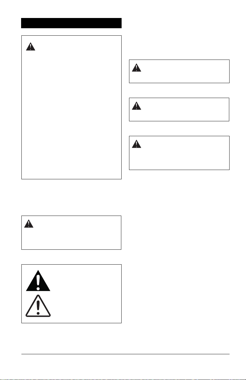
Safety Alert Symbol
These are safety alert
symbols. They mean:
• ATTENTION!
• YOUR SAFETY IS
INVOLVED!
When you see this symbol:
• BECOME ALERT!
• OBEY THE
MESSAGE!
SIGNAL WORDS
The safety alert symbols above and signal
words below are used on decals and in this
manual.
Read and understand all safety messages.
1. Danger
DANGER: Indicates an
IMMINENTLY HAZARDOUS
SITUATION! If not avoided, WILL
RESULT in death or serious injury.
2. Warning
WARNING: Indicates a
POTENTIALLY HAZARDOUS
SITUATION! If not avoided, COULD
RESULT in death or serious injury.
3. Caution
CAUTION: Indicates a
POTENTIALLY HAZARDOUS
SITUATION! If not avoided, MAY
RESULT in minor or moderate injury .
It may also be used to alert against
unsafe practices.
4. Notice
NOTICE: Indicates information or procedures
that are considered important but not hazard
related. If not avoided property damage could
result.
5. Important
IMPORTANT: Indicates general reference
information worthy of special attention.
SAFETY DECALS
This cutting machine is capable of amputating
hands and feet and throwing objects. Failure
to observe the following safety instructions
could result in serious injury or death.
The safety decals on your machine are visual
reminders of the important safety information
found in this manual. All messages found on
your unit must be fully understood and
carefully followed. Safety decals found on the
machine are explained below.
Always replace missing or damaged safety
decals. Replacement decals can be found in
the parts manual for your machine and
ordered from your dealer.
Refer to Figure 2 for safety decal locations.
EN - 4
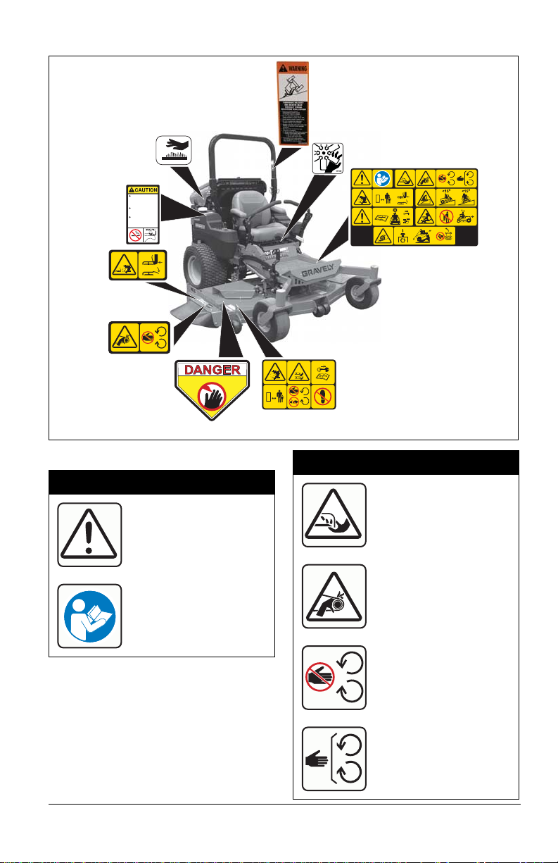
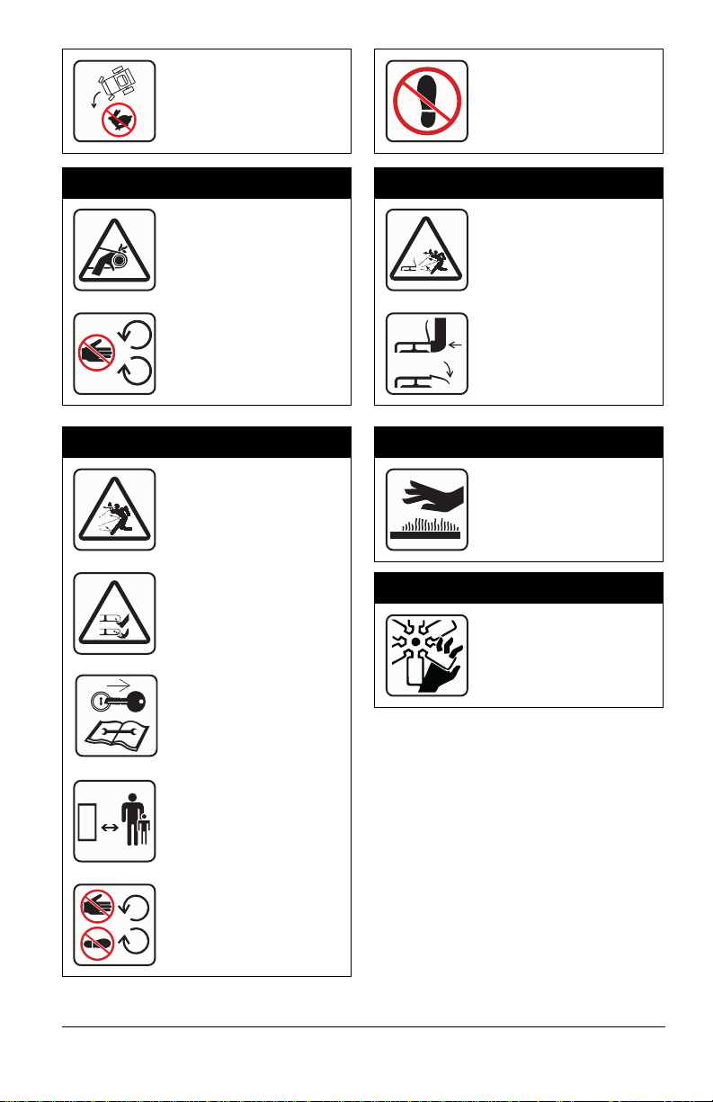
1. Safety Decal Identification
Figure 2
1
2
5
3
6
7
4
8
9
Never fill tank when
engine is running,
hot or unit is indoors.
Never overfill fuel
tank.
Replace fuel cap
securely and clean
up spilled fuel.
08000611A
07800401
KEEP HANDS and FEET AWAY
P
07800403
02988100
2. Safety Decal Description
1. DANGER!
DANGER!
Read and understand the
operator’s manual before
operating unit.
1.1 Amputation Hazard
EN - 5
To avoid amputation
hazard do not put hands
near rotating blades.
To avoid amputation
hazard do not put hands
near moving belts.
Keep hands away from all
rotating or moving parts.
Keep all guards and
shields in place.
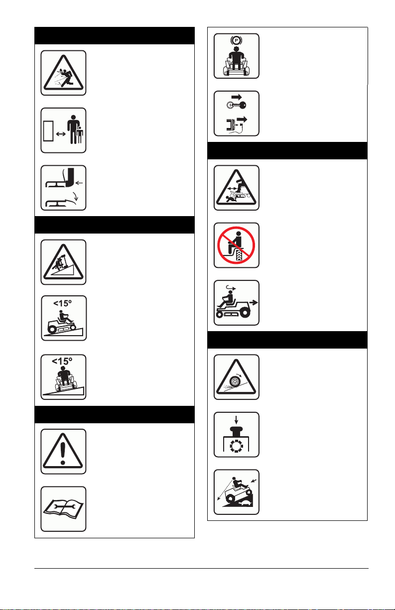
1.2 Discharge Hazard
Discharge Hazard –
NEVER direct discharge
toward people, pets or
property. Thrown objects
can cause injury or
damage.
Keep children and others
away from unit while unit is
in operation.
P
Set parking brake.
Remove key and
disconnect spark plug
before servicing or making
adjustments to unit.
1.5 Bystander Hazard
Do not operate mower
unless all guards are in
operating position or
bagger is attached.
1.3 Tipping Hazard
Avoid tipping hazard.
DO NOT operate on slopes
over 15°.
DO NOT operate on slopes
over 15°.
1.4 Service Hazard
Before servicing unit do the
following:
DO NOT operate the unit in
the presence of
bystanders.
Do not carry passengers.
Look behind when
operating the unit in
reverse.
1.6 Loss of Traction Hazard
If loss of traction is
experienced do the
following:
Disengage PTO.
Read owners manual
before servicing or making
adjustments to unit.
Look before backing.
Proceed off slope slowly.
EN - 6
Do not try to turn or speed
up.
DO NOT step or stand in
this area.
2. DANGER!
3. DANGER!
Discharge Hazard –
NEVER operate unit
without discharge chute
in operating position.
Thrown objects can
cause injury or damage.
Do not operate mower
unless all guards are in
operating position or
bagger is attached.
Discharge Hazard –
NEVER direct discharge
toward people, pets or
property. Thrown objects
can cause injury or
damage.
Amputation Hazard –
NEVER stick hands or feet
under deck or shielded
areas.
Shut off engine, remove
key, and read manual
before servicing or making
adjustments to unit.
4. DANGER!
Discharge Hazard –
NEVER operate unit
without discharge chute
in operating position.
Thrown objects can
cause injury or damage.
Do not operate mower
unless all guards are in
operating position or
bagger is attached.
5. HOT SURFACES!
DO NOT touch parts
which are hot from
operation. ALW A YS al low
parts to cool.
6. ROTATING PARTS!
AVOID INJURY. Stay
clear of rotating parts.
Keep children and others
away from unit while unit is
in operation.
Keep feet and hands away
from all rotating or moving
parts.
EN - 7
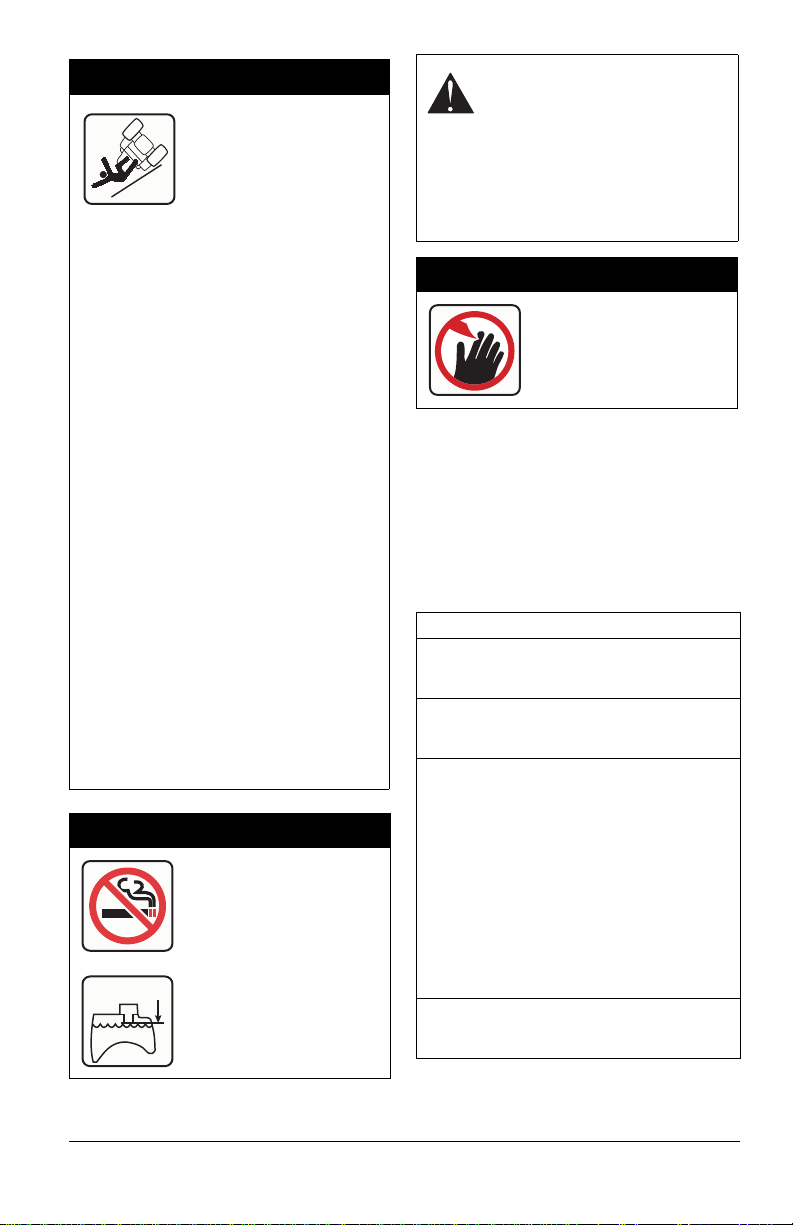
7. WARNING!
WARNING: Over Filling may cause
severe damage to evaporative
system!
SERIOUS INJURY OR
DEATH MAY RESULT
FROM MACHINE
ROLLOVER
• Failure to follow these instructions
could result in serious injury or
death
• Do not operate machine on steep
slopes or near drop offs
• Avoid sharp and/or quick turns
• Do not exceed the machine weight
rating of the ROPS
• Always use the seat belt when the
ROPS is locked in the upright
position
• Do not jump if machine tips
• If ROPS is foldable
– Always keep the ROPS fully
extended
– WHEN ROPS MUST BE
DOWN
• Do not use seat belt
• Drive with extra care
• If equipped with seat platform:
Do not operate machine without seat
platform pins in place or locks engaged.
ROLLOVER PROTECTIVE STRUCTURE
To maintain operator protection and roll
bar certification:
• Replace a damaged roll bar, do
NOT attempt to repair or modify.
• Any alteration of the roll bar must
be approved by the manufacturer.
• DO NOT exceed the machine
weight rating of the roll bar.
8. CAUTION!
No smoking.
MAX. FILL
Fill fuel tank to bottom of
neck – MAXIMUM.
• Never fill fuel tank when engine is
running, hot or unit is indoors. Never
overfill fuel tank.
• Replace fuel cap securely and clean up
spilled fuel.
9. DANGER!
ALW A YS keep hands and
feet away from discharge
chute.
SAFETY RULES
This cutting machine is capable of amputating
hands and feet and throwing objects. Failure
to observe the following safety instructions
could result in serious injury or death.
The following safety instructions are based
on the B71.4 specifications of the American
National Standards Institute in effect at the
time of production.
Training
Read, understand, and follow all instructions
on the machine and in the manuals before
starting.
Be sure the area is clear of bystanders and
pets before operating. Stop machine if
anyone enters the area.
Improper use of power equipment can cause
serous permanent injury or death to the
operator or a bystander.
Understand:
• How to operate all controls
• The functions of all controls
• How to STOP in an Emergency
• Braking and steering characteristics
• Turning radius and clearances
If the operator or the mechanic cannot read
the manual, it is the owner’s responsibility to
explain it to them.
Always train any inexperienced operators
and require them to read and understand all
manuals and decals.
EN - 8

Only allow responsible adults, who are
familiar with the instructions, to operate this
machine.
Only the user can prevent and is responsible
for accidents or injuries occurring to
themselves, other people or property.
Operator Age
Do not allow children under the age of 18 to
operate any outdoor power equipment.
Local regulations may restrict the age of the
operator.
Data indicates operators age 60 years and
above are involved in a large percentage of
riding mower-related injuries.
These operators should evaluate their ability
to operate the riding mower safely enough to
protect themselves and others from serious
injury.
Children
Tragic accidents can occur if the operator is
not alert to the presence of children.
Children are often attracted to the machine
and the mowing activity. Never assume that
children will remain where you last saw
them.
Be alert and turn machine off if a child enters
the area.
Before and while backing, look behind and
down for small children.
Never carry children, even with the blade(s)
shut off. They may fall off and be seriously
injured or interfere with safe machine
operation. Children who have been given
rides in the past may suddenly appear in the
mowing area for another ride and be run
over or backed over by the machine.
Never allow children to operate the machine.
Use extreme care when approaching blind
corners, shrubs, trees, or other objects that
may block your view of a child.
Keep children out of the mowing area and in
the watchful care of a responsible adult
other than the operator.
Personal Protection
DO NOT wear loose clothing or jewelry and
tie back hair that may get caught in rotating
parts.
Wear adequate outer garments.
NEVER wear open sandals or canvas shoes
during operation. Wear adequate safety
gear, protective gloves and footwear.
Wear proper footwear to improve footing on
slippery surfaces
Always wear eye and ear protection when
operating machine.
Before Operating
Keep all nuts and bolts tight to be sure the
equipment is in safe working condition.
Maintain the machine to be in compliance
with the maintenance schedule.
Clean grass and debris from unit, especially
from around muffler and engine, to help
prevent fires.
Check parking brake operation frequently.
Adjust and service as required.
Inspect unit before each use for missing or
damaged decals and shields, correctly
operating safety interlock system, and
deterioration of grass catchers. Replace or
repair as needed.
Ensure Safety Interlock System is
functioning properly. DO NOT operate unit if
safety interlock is damaged or disabled.
Start and operate unit only when seated in
operator’s position. Steering control levers
must be in neutral, PTO disengaged and
parking brake set when starting engine.
Never tamper with safety devices. Check
their proper operation regularly.
Keep machine free of grass, leaves, or other
debris build-up. Clean up oil or fuel spillage
and remove any fuel-soaked debris.
Operation
Be sure the area is clear of bystanders
before operating. Stop machine if anyone
enters the area.
Never operate machine in a closed or poorly
ventilated area.
ALWAYS maintain unit in safe operating
condition. Damaged or worn out muffler can
cause fire or explosion.
This product is equipped with an internal
combustion type engine. DO NOT use unit
on or near any unimproved, forest-covered
or brush covered land unless exhaust
system is equipped with a spark arrester
meeting applicable local, state or federal
laws. A spark arrester, if it is used, must be
maintained in effective working order by
operator.
Do not operate machine while under the
influence of alcohol or drugs.
EN - 9

Do not put hands or feet near rotating parts
or under the machine. Keep clear of the
discharge opening at all times.
DO NOT touch parts which are hot. Allow
parts to cool.
Do not operate machine without the entire
grass catcher, discharge guard, or other
safety devices in place and working.
Always keep hands and feet away from all
pinch points.
Avoid slippery surfaces. Always be sure of
your footing.
Never carry passengers.
Never direct discharged material toward
anyone. Avoid discharging material against
a wall or obstruction. Material may ricochet
back toward the operator. Stop the blade(s)
when crossing gravel surfaces.
Never engage PTO when attachment,
including mower blades, is not in use.
Always turn off power to attachment when
not in active use such as traveling or
crossing driveways.
Always disengage PTO, stop unit and
engine, remove key, engage parking brake
and allow moving parts to stop before
leaving operator’s position.
Never engage PTO while raising the
attachment, including mower blades, or
when attachment is in the raised position.
Keep safety devices or guards in place and
functioning properly. Never modify or
remove safety devices.
Do not mow in reverse unless absolutely
necessary. Always look down and behind
before and while backing.
Stop engine before removing grass catcher
or unclogging chute.
Slow down before turning.
If you strike a foreign object, stop and
inspect the machine. Repair, if necessary,
before restarting.
Never leave a running machine unattended.
Always turn off blade(s), set parking brake,
stop engine and remove key before
dismounting.
Disengage blade(s) when not mowing. Shut
off engine and wait for all parts to come to a
complete stop before cleaning the machine,
removing the grass catcher, or unclogging
the discharge guard.
Know the weight of loads. Limit loads to
those you can safely control and the unit can
safely handle.
Operating Conditions
Always check overhead and side clearances
carefully before operation.
Watch for traffic when operating near or
crossing roadways.
Clear the area of objects such as rocks,
wire, toys, etc., which could be thrown by the
blades.
Check for weak spots on docks, ramps or
floors. Avoid uneven work areas and rough
terrain. Stay alert for hidden hazards or
traffic.
Use care when approaching blind corners,
shrubs, trees or other objects that may
obscure vision.
Dust, smoke, fog, etc. can reduce vision and
cause an accident.
Operate machine only in daylight or good
artificial light.
Slope Operation
Slopes are a major factor related to loss of
control and tip-over accidents, which can
result in severe injury or death. Operation on
all slopes requires extra caution. If you
cannot back up the slope or if you feel
uneasy on it, do not mow it.
DO NOT operate on slopes of more than
15°.
Mow up and down slopes, not across.
Watch for holes, ruts, bumps, rocks, or other
hidden objects. Uneven terrain could
overturn the machine. Tall grass can hide
obstacles.
Do not mow on moist or wet grass. Tires
may lose traction causing a loss of control.
Use extra care while operating machine with
grass catchers or other attachments; they
can affect the stability of the machine. Do
not use on steep slopes.
Keep all movements on the slope slow and
gradual. Do not make sudden changes in
speed or direction, which could cause the
machine to roll over.
Avoid starting, stopping, or turning on a
slope. If the tires lose traction, disengage
the blade(s) and proceed slowly straight
down the slope.
EN - 10

Operation on slopes may lead to loss of
steering control. When operating on slopes
be prepared to react to an emergency
situation:
• Return steering levers to neutral
position.
• Immediately set parking brake.
• Turn off PTO and engine.
DO NOT try to stabilize the machine by
putting your foot on the ground.
DO NOT park on slopes unless necessary.
When parking on slope always chock or
block wheels. Always set parking brake.
Choose a low ground speed so you will not
have to stop or shift while on a slope.
DO NOT operate near drop-offs, ditches, or
embankments. Unit can suddenly turn over if
a wheel is over the edge of a cliff or ditch, or
if an edge caves in.
Do not bypass transmission or allow
transmission to free-wheel when on a slope.
Fuel
T o avoid personal injury or property damage,
use extreme care in handling fuel. Fuel is
extremely flammable and the vapors are
explosive.
Replace fuel cap securely and clean up
spilled fuel before starting engine.
Extinguish all cigarettes, cigars, pipes, and
other sources of ignition.
Use only an approved fuel container.
Never store the machine or fuel container
where there is an open flame, spark, or pilot
light such as on a water or space heater or
other appliances.
Never fill containers inside a vehicle or on a
truck or trailer bed with a plastic liner.
Always place containers on the ground away
from your vehicle before filling.
Never fuel the machine indoors.
Never remove gas cap or add fuel with the
engine running. Allow engine to cool before
fueling.
Fuel is highly flammable and its vapors are
explosive. Handle with care. Use only an
approved container with an appropriately
sized dispensing spout.
NO smoking, NO sparks, NO flames.
Remove equipment from the trailer and
refuel it on the ground. If this is not possible,
then refuel such equipment with a portable
container, rather than from a fuel dispenser
nozzle.
Keep the nozzle in contact with the rim of
the fuel tank or container opening at all
times until the fueling is complete. Do not
use a nozzle lock-open device.
Never overfill fuel tank. Replace gas cap
and tighten securely.
If fuel is spilled on clothing, change clothing
immediately.
Towing
Follow the manufacturer’s recommendations
for weight limits for towed equipment and
towing on slopes.
NEVER allow children or others in or on
towed equipment.
Tow only with a machine that has a hitch
designed for towing. Do not attach towed
equipment except at the hitch point.
On slopes, the weight of the towed
equipment may cause loss of control.
Travel slowly and allow extra distance to
stop.
Accessories
Follow the manufacturer’s recommendation
for wheel weights or counterweights
Check grass catcher components and the
discharge guard frequently nad replace with
the manufacturer’s recommended parts,
when necessary.
Use only Ariens Company-recommended
attachments that are appropriate to your use
and can be used safely in your application.
Batteries
Avoid Electric Shock. Objects contacting
both battery terminals at the same time may
result in injury and unit damage. DO NOT
reverse battery connections.
Reverse connections may result in sparks
which can cause serious injury. Always
connect positive (+) lead of charger to
positive (+) terminal, and negative (-) lead to
negative (-) terminal.
ALWAYS disconnect negative (-) cable
FIRST and positive (+) cable SECOND.
ALWAYS connect positive (+) cable FIRST,
and negative (-) cable SECOND.
EN - 11

Explosive Gases from battery can cause
death or serious injury. Poisonous battery
fluid contains sulfuric acid and its contact
with skin, eyes or clothing can cause severe
chemical burns.
No flames, No sparks, No smoking near
battery.
ALW AYS wear safety glasses and protective
gear near battery. Use insulated tools.
ALWAYS keep batteries out of reach of
children.
Battery posts, terminals and related
accessories contain lead and lead
compounds, chemicals known to the State of
California to cause cancer and reproductive
harm. Wash hands after handling.
Rollover Protection System (ROPS)
Frequently inspect ROPS and seat belt for
damage or loose hardware.
Use extreme care when working close to
fences, ditches, or on hills.
Check overhead clearance carefully before
driving under any objects.
Always wear seat belt while operating the
unit with the ROPS in the upright position.
Only lower ROPS for transport.
Do not wear a seat belt while operating the
unit with the center bar in the lowered
position.
Do not weld, cut, drill or modify ROPS in any
manner unless instructed by the
manufacturer.
Service
Maintain or replace safety and instruction
labels, as necessary.
Keep unit free of debris. Clean up oil or fuel
spills.
ALWAYS block wheels and know all jack
stands are strong and secure and will hold
weight of unit during maintenance.
Release any pneumatic or hydraulic
pressure from components slowly.
NEVER attempt to make any adjustments to
unit while engine is running (except where
specifically recommended). Stop engine,
remove key or spark plug wire and wait for
all moving parts to stop before servicing or
cleaning.
Lower cutting deck unless a positive
mechanical lock is used.
Allow engine to cool before servicing.
Moving parts can cut or amputate fingers or
a hand. On multiblade mowers, rotation of
one blade will cause all blades to rotate.
Never weld or straighten mower blades.
Never make adjustments or repairs with the
engine running.
Mower blades are sharp. Wrap the blade or
wear gloves, and use extra caution when
servicing them.
ALWAYS keep body and hands away from
pin holes or nozzles which eject hydraulic
fluid under pressure.
Transporting Unit
Use extra care when loading or unloading
the machine into a trailer.
Secure unit chassis to transport vehicle.
Never secure from rods or linkages that
could be damaged.
Do not transport machine while engine is
running.
ALWAYS turn off power to attachment and
shut off fuel when transporting unit.
Storage
NEVER store unit with fuel in fuel tank,
inside a building where any ignition sources
are present.
Keep machine free of grass, leaves, or other
debris build-up. Clean up oil or fuel spillage
and remove any fuel-soaked debris. Allow
machine to cool before storing.
For extended storage, shut off fuel and
clean unit thoroughly . See engine manual for
proper storage.
EN - 12
ASSEMBLY
Transport
Position
Operating
Position
Figure 3
WARNING: AVOID INJURY.
Read and understand entire
Safety section before proceeding.
UNIT ASSEMBLY
Package Contents
Unit, Mower Deck and Literature Pack
Preparation Checklist
Refer to the Owner/Operator manual as
required.
1. Unpack Unit – Remove wrap and
packaging materials.
2. Remove Unit From Container – Open
bypass valves (See To P ush The U nit on
page 23).
3. Push unit from container onto a level
surface.
4. Close the bypass valves.
5. Check Tire Pressures – See
Specifications on page 47.
CAUTION: Avoid injury! Explosive
separation of tire and rim parts is
possible when they are serviced
incorrectly:
• Do not attempt to mount a tire
without the proper equipment
and experience to perform the
job.
• Do not inflate the tires above the
recommended pressure.
• Do not stand in front or over the
tire assembly when inflating.
Use a clip-on chuck and
extension hose long enough to
allow you to stand to one side.
10. Check Engine Oil Level – Check and add
oil if needed. See engine manual for
specifications.
11. Check Hydraulic Fluid Level – Check and
add oil if needed. See Check Hydraulic
Fluid Level on page 28.
12. Check Coolant Level
13. F ill Engine Fuel Tank – Add clean fuel to
the fuel tank. See Filling Fuel Tank on
page 21.
IMPORTANT: Refer to engine manual for fuel
type.
14. Inspect Hardware – Check for loose
hardware.
15. Check Safety Interlock System – Check
to see that the interlock system operates
correctly (See Safety Interlock System on
page 16).
WARNING: FAILURE OF
INTERLOCK together with
improper operation can result in
severe personal injury.
16. Lubrication – Lubricate all fittings per
maintenance label under seat and check
hydraulic oil level (See Maintenance
Schedule on page 24).
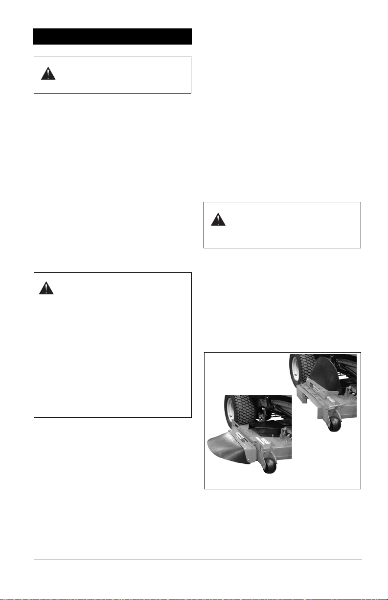
17. Remove the knob retaining the discharge
chute from the transport position and
place the discharge chute in the
operating position. Return and tighten
knob in original position on deck for
storage.
6. Locate anti-rattle knobs in literature pack
and install in ROPS uprights on both
sides. Raise Rollover Protection Structure
(ROPS) center bar – See Rollover
Protection Structure (ROPS) on page 16.
7. Adjust Seat – See Seat Adjustments on
page 20 and Service Position on
page 27.
8. Check S teering Lever Positions – See
Adjusting the Parking Brake on page 37.
9. Charge Battery – Remove battery from
unit and charge (See Battery on
page 33).
Prepare Seat
1. Remove hairpin and clevis from shipping
position on left side of seat and reinstall
as shown below.
EN - 13
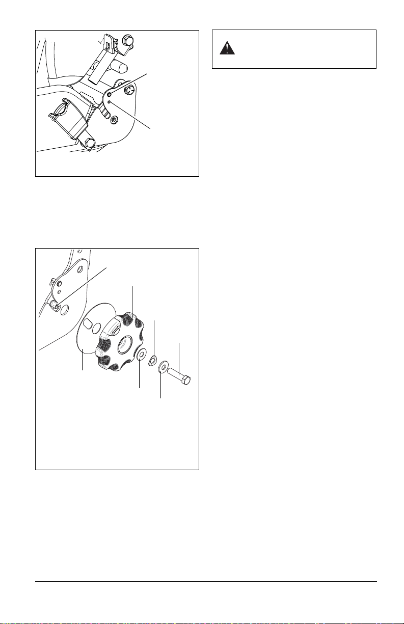
2. Secure adjustment dial to seat as shown
Figure 4
Reinstall
hairpin and
clevis here.
Shipping
position for
hairpin and
clevis.
Figure 5
1. Recliner Pin
2. Bearing
3. Seat Adjustment Dial
4. Washer
5. Bowed Washer
6. Flat Washer
7. 3/8-16 x 1 1/2" Hex Bolt
1
2
4
3
5
6
7
below. Use socket wrench to hand tighten
bolt until dial is difficult to rotate, then
loosen bolt slightly until dial rotates freely.
IMPORTANT: DO NOT loosen bolt more than
one full turn.
WARNING: FAILURE OF
CONTROLS could result in death
or serious injury.
3. Check Deck Level – Check unit to ensure
deck level set at factory has been
maintained (See Leveling the Mower
Deck on page 42).
4. Check Function of all Controls – Ensure
unit runs and performs properly.
EN - 14
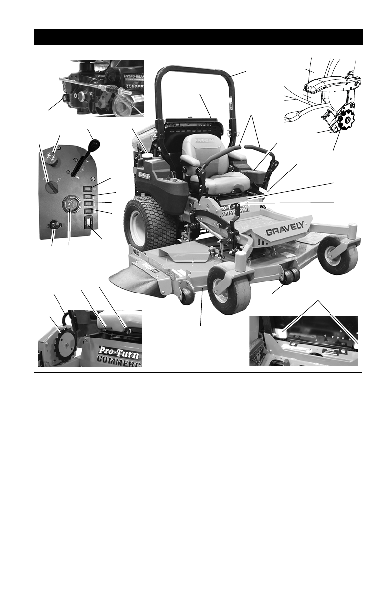
CONTROLS AND FEATURES
1
2
3
10
11
12
13
14
15
8
7
5
19
9
4
18
Figure 6
17
21
23
22
16
24
20
25
6
26
27
1. Fuel Tanks and Caps
2. Steering Levers
3. Hydraulic Oil Reservoirs
4. Ignition Switch
5. Hour Meter
6. Coolant Temperature Gauge
7.
Throttle Lever
8. Battery Charge Light
9. Power Take Off (PTO) Switch
10. Battery
11. Fuel Control Lever
12. Mower Lift Pedal
13. Mower Deck
14. Transport Lock Lever
EN - 15
15. Seat Adjustment Lever
16. Seat Height/Pressure Adjustment Knob
17. Parking Brake Lever
18. Transaxle Bypass Valve
19. Oil Pressure Light
20. Engine O verheat Light
21. Height- of-Cut (HOC) Index Wheel
22. Engine Preheat Indicator
23. Roll-Over Protection Structure (ROPS)
24. Radiator Filler and Cap
25. Anti-Scalp Wheels
26. 12V Auxiliary Power Port
27. Seatback Adjustment Dial

OPERATION
WARNING: AVOID INJURY.
Read and understand entire
Safety section before proceeding.
CONTROLS AND FEATURES
See Figure 6 for Controls and Features
locations.
Safety Interlock System
WARNING: Safety interlock
system failure and improper
operation of unit can result in
death or serious injury. Test this
system each time the unit is
operated. If this system does not
function as described, do not
operate until repairs are made.
Perform the following tests to ensure the
safety interlock system is working properly. If
the unit does not perform as stated, contact
your Gravely dealer for repairs.
NOTICE: When the parking brake is
engaged, the steering levers are locked in
neutral.
Test
Steering
Levers
STARTING INTERLOCK
1 Neutral Off Engaged Starts
2Forward,
Neutral,
Reverse
3Forward,
Neutral,
Reverse
OPERATING INTERLOCK (ENGINE ON)
4* Forward,
Neutral,
Reverse
5* Forward,
Neutral,
Reverse
* Operator lifts off seat.
PTO Parking
Brake
On Engaged or
Disengaged
On
Disengaged Does
or
Off
On Engaged or
Disengaged
On
Disengaged Shuts
or
Off
Engine
Does
Not Start
Not Start
Shuts
Off
Off
ROLLOVER PROTECTION STRUCTURE (ROPS)
Frequently inspect ROPS and seat belt for
damage or loose hardware.
Use extreme care when working close to
fences, ditches, or on hills.
Check overhead clearance carefully before
driving under any objects.
ALWAYS wear seat belt while operating the
unit with the ROPS in the upright position.
Do not wear a seat belt while operating the
unit with the center bar in the lowered
position.
IMPORTANT: Do not weld, cut, drill or modify
ROPS in any manner unless instructed by the
manufacturer.
Lower Center Bar
(Figure 7)
WARNING: Lower the center bar
only when necessary to drive under
an object. There is no rollover
protection with the center bar in the
down position.
1. Loosen but do not remove the two antirattle knobs on the front of the hinge
plate.
2. Remove the two hair pins and then
remove the ROPS lock pins from the
hinge plate.
3. Lower the center bar into down position.
4. Install the ROPS lock pins in the hinge
plate and secure with the hair pins.
Raise Center Bar
(Figure 7)
1. Remove the two hair pins and then
remove the ROPS lock pins from the
hinge plate.
2. Raise the center bar into up position.
3. Install the ROPS lock pins in the hinge
plate and secure with the hair pins.
4. Tighten anti-rattle knobs until threads
place tension on upper bar. Do not
overtighten.
NOTICE: Return the center bar to the raised
position when clear of obstacles.
EN - 16

Lowered
Position
Figure 7
Raised
Position
1. Lock Pin
1
Direction
1
2
3
of Travel
Left Turn Push right lever
Lever Position
farther forward
than the left lever.
Parking Brake Interlock System
With the parking brake engaged, the steering
levers must be locked in neutral.
With the parking brake disengaged, the
engine must not start and the engine must
shut off if the operator lifts from the seat.
Steering Levers
The steering levers control speed and
direction. In addition, they will stop the unit.
T o stop, return both steering levers to neutral.
Direction
of Travel
Forward Push both levers
Reverse Pull both levers
Right Turn Push left lever
Lever Position
forward from
neutral position.
backward from
neutral position.
farther forward
than the right
lever.
Stop Return both
levers to neutral
position.
NOTICE: The steering controls are
mechanically locked in neutral whenever the
parking brake is engaged.
NOTICE: Aggressive turning can scuff or
damage lawns. ALWAYS keep both wheels
rotating when making sharp turns. DO NOT
make turns with inside wheel completely
stopped. To obtain minimum turning radius,
slowly reverse inside wheel while moving
outside wheel slowly forward.
Ignition Switch
Operate the ignition
switch with the
removable key. The
switch has three
positions:
•Off (1)
•On (2)
•Start (3)
To start the engine, turn the key to Start, then
release to On. To stop the engine, turn the
key to Off.
Engine Preheat Light
Indicates when the engine
preheater is energized.
Preheater energizes for
approximately 5 seconds
when the key switch is
turned to the Run position.
Oil Pressure Light
Indicates when engine oil
pressure is low.
NOTICE: It does not
indicate engine oil level.
See Troubleshooting on page 45 or refer to
Engine Manual for details.
EN - 17

Coolant T e mpe rature Gauge
2
1
1
OFF
ON
Indicates
temperature of
engine coolant.
Engine
Overheat Light
Indicates when
coolant temperature
exceeds 93.3
F). See Troubleshooting
on page 45.
o
C (200o
Engine Overheating Wa rning Alarm
When the coolant
temperature exceeds
o
C (220o F) an
104.4
alarm located behind the
seat will sound to alert
the operator that the
engine coolant is
will continue to sound until the key switch is
turned to the Off position or the coolant
temperature drops below 104.4
overheating. The alarm
o
C (220o F).
Battery Charge Indicator
Lights when the key is in
the run position and the
charging system is not
charging the battery.
Transax l e By pass Valves
The unit can be
moved without the
engine running by
bypassing the
transaxles. The
bypass valves (1)
are located on the
transaxles near the
rear tires. See To
Push The Unit on
page 23.
NOTICE: Make sure
both transaxles are
set to neutral before
pushing the unit.
IMPORTANT: DO NOT tow the unit.
Transport the unit on an appropriate truck or
trailer.
Power Take Off (PTO) Switch
Power take off (PTO)
switch engages and
disengages the mower
blades.
Pull the power take off
(PTO) switch to On
position to engage
mower blades.
Push the power take off
(PTO) switch to Off
position to disengage
mower blades.
NOTICE: The engine will not start unless the
steering control levers are in the neutral
position, the PTO switch is in the Off position
and parking brake is set.
Throttle Lever
The throttle lever
changes the engine
speed.
Move the throttle lever
to Fast (1) to increase
engine speed.
Move the lever to Slow
(2) to decrease engine
speed.
MOWER LIFT PEDAL AND HEIGHT-OF-CUT (HOC) INDEX WHEEL
Mower lift pedal raises and lowers mower
deck for mowing or transport. Height-of-cut
(HOC) index wheel sets desired cutting
height or transport position. When in the lock
position, the transport lock lever allows the
deck to automatically lock in the highest (14
mm (5.5") HOC) position when the lift pedal is
pushed fully forward.
EN - 18

Transport Lock Lever
RELEASE OFF
TRANSPORT LOCK
CUT
HEIGHT
Figure 8
1. Mower Lift Pedal
2. Height of Cut (HOC) Index Wheel
3. Transport Lock Lever
4. HOC Setting Indicator
1
2
3
2
Off
Position
3
4
1
2
To m ove the mower deck into the
transport position:
1. Push mower lift pedal fully
forward. The lever will
automatically lock in the transport
position.
2. Release mower lift pedal.
To release the mower deck fr om
the transport position:
1. Push mower lift pedal to
relieve pressure from the
transport lock lever.
2. Pull back on the transport lock
lever.
3.Release the mower lift pedal.
NOTICE: With the lock lever in the lock
position (in) the deck will automatically lock at
transport height whenever the lift pedal is
pressed fully forward. To disable this feature
move the transport lock lever out and to the
rear to the Off position.
Height of Cut (HOC)
(Figure 8)
1. Push mower lift pedal to release deck
pressure from HOC index wheel.
2. If locked, move transport lock lever to
unlocked position.
3. Rotate HOC index wheel to the desired
HOC setting. Height setting is viewed in
the center the window on the top of the
HOC adjustment assembly.
4. Release mower lift pedal.
Fuel Control Lever
Controls fuel flow
from the left or
right fuel tank to
the engine.
Move the lever to
the Left Tank or
Right Tank
position to draw
fuel from that tank.
Parking Brake Lever
Engages and disengages
parking brake.
Push lever forward to
disengage (1) parking
brake.
Pull lever backward to
engage (2) parking brake.
EN - 19

SEAT ADJUSTMENTS
Figure 9
1. Height Adjustment Switch
1
Figure 10
Adjust to 3 – 6 mm (1/8 – 1/4")
gap between threaded washer
and seat isolator.
1. Threaded Washer
2. Seat Isolator
2
1
WARNING: Make all seat
adjustments with unit stationary,
parking brake engaged and
engine shut off.
Setting Seat Position
1. Pull seat adjustment lever outward and
slide seat forward or backward to desired
position.
2. Release lever and slide seat slightly
forward or backward to lock seat position.
Setting Seatback Angle
Turn adjustment knob counterclockwise to
move seatback forward. Turn knob clockwise
to move seatback rearward.
Setting Lumbar Support
Lift lever to increase lumbar support. Lower
lever to decrease support.
Setting Armrest Angle
Turn height adjustment knob
counterclockwise to raise the front of the
armrest or clockwise to lower the front of
armrest.
Setting Seat Height/Pressure
(Figure 9)
While seated in operator’s position, move
seat switch left to raise seat cushion or right
to lower seat cushion. Key must be in the
"On" position to raise seat.
Seat Retainer Adjustment
(Figure 10)
Damage to the seat isolators may occur if
units are operated for an extended period of
time with the seat retainer threaded washer
adjusted too far from the isolator.
The correct adjustment for the seat retainer threaded washer is 3 – 6 mm (1/8 – 1/4") below the bottom of the isolator mount.
HOUR / MAINTENANCE METER
Hour Meter-only Models
Hour meter measures engine runtime and
cannot be reset.
Maintenance Models
(Figure 11)
When the key is in the on position, the T imer
mode displays. Press the Mode button to
toggle between different models.
Timer: Measures engine runtime until reset.
To reset the timer, press the Mode button to
select TMR1 mode and then hold Mode
button for 3 seconds.
IMPORTANT: Turn ignition key to the off
position when unit is not in use. Some meters
may count hours when the key is in the on
position, even if the engine is off. This results
in inaccurate maintenance intervals.
Service Alerts: Counts down hours until
service is needed and displays "Now" when
service id due. Service time is measured for:
• Engine oil and filter changes (CHG OIL)
EN - 20

• Hydraulic oil and filter changes (CHG H
Mode Button
Figure 11
OIL)
• Air filter service (SVC AIRFILTER)
The service intervals preset into the hour
meter are:
• Hydraulic oil and filter: First 75 hours and
every 400 hours thereafter
• Engine oil and filter: First 25 hours and
every 100 hours thereafter
• Air filter: Every 100 hours
NOTICE: The preset engine oil services
intervals are normal recommended intervals.
Specific engine manufacturer’s
recommendations may vary.
To clear a service mes sage, press the Mode
button to select Service Alert mode and then
hold the Mode button for 3 seconds.
12-VOLT AUXILIARY POWER PORT
Use the auxiliary power port to run
compatible 12-volt accessories. The key must
be in the ON position to use.
T o reduce battery drain, only use accessories
when the engine is running. To avoid batteryand electrical-system damage, DO NOT use
high-draw accessories such as light kits, and
turn accessories off before plugging into port.
To help prevent damage, do not use port to
charge delicate accessories such as cell
phones.
NOTICE: The power port reaches 15 amps at
peak and 5 amps continuous.
If port does not have power, a fuse may be
blown. See Electrical Service on page 34.
Keep the protective cap on the port when not
in use.
IMPORTANT: Only use compatible
accessories. DO NOT use with a 110-volt
voltage inverter.
FILLING FUEL TANK
WARNING: AVOID INJURY . Read
and understand entire Safety
section before proceeding.
To add fuel to the fuel tank:
1. Move unit to an open, well-ventilated
area.
2. Stop engine and allow it to cool.
3. Clean fuel cap and surrounding area to
prevent dust, dirt, and debris from
entering fuel tanks.
4. Remove fuel caps.
IMPORTANT: See Specifications on page 47
for correct type and grade of fuel and fuel
tank capacity.
5. Fill fuel tanks to the bottom of filler neck.
IMPORTANT: DO NOT OVERFILL! Filling to
the recommended level ensures a vapor gap
required to allow for fuel expansion.
6. Replace fuel caps and tighten.
7. ALWAYS clean up spilled fuel.
PRE-START
CAUTION: Make sure all
hardware is tight, all safety
devices are in place and all
adjustments are made correctly.
1. Check Safety Interlock System
If this system does not function as described
do not operate until repairs are made.
2. Check Air Cleaner
Check air filter for dirt and overall condition.
Clean as required. Follow engine manual
maintenance schedule.
3. Check Engine Fuel and Crankcase
Oil
Check and add fuel if required. Check that
engine crankcase oil is full. Follow engine
manual maintenance schedule.
4. Check Tire Pressure
See Specifications on page 47 for correct tire
pressure.
5. Check Hydraulic Fluid Level
See Check Hydraulic Fluid Level on page 28.
6. Adjust Seat
Be sure all controls can be reached safely
from operator’s position. See Seat
Adjustments on page 20.
EN - 21

7. Set Cutting Height
Make sure the deck is set to the correct
cutting height. See Height of Cut (HOC) on
page 19.
8. Check Radiator Screen
Check radiator screen and remove any
debris. See Maintenance Schedule on
page 24.
STARTING AND SHUT OFF
CAUTION: Read entire
Owner/Operator and Engine
Manual first. DO NOT attempt to
start engine at this time.
NOTICE: If unit runs out of fuel the engine
must be primed prior to starting the engine.
Refer to engine manual for detailed
instructions.
IMPORTANT: Do not use ether or starting
fluid to attempt to start the engine. Severe
damage will occur.
Starting
To start engine:
1. Move the steering levers to the neutral
position.
2. Move the PTO switch to the Off position.
3. Engage parking brake.
4. Place the throttle control halfway between
the slow and fast positions.
5. Insert the ignition key in the switch and
turn the key switch to the On position.
The engine preheat indicator will glow.
Keep the switch in this position until the
engine preheat indicator stops glowing.
6. Turn the key switch to the Start position,
crank and start engine.
7. As soon as the engine starts, release the
key.
8. If the engine does not start after two
attempts see Troubleshooting on
page 45.
IMPORTANT: Do not crank the engine
continuously for more than 20 seconds at
a time. If the engine does not start, allow a
5 – 30 second cool down period between
starting attempts.
To stop the engine:
1. Bring the steering levers to neutral.
Disengage the PTO and engage the
parking brake.
2. Move the throttle lever to the Slow
position.
3. Allow engine to idle before shutting off
unless there is a safety problem that
requires immediate shut-down.
4. Turn the ignition key to the Off position.
STOPPING IN AN EMERGENCY
WARNING: Operating unit on
slopes may lead to loss of
steering control. When operating
on slopes be prepared to react to
an emergency situation.
1. Return steering levers to neutral position.
2. Immediately set parking brake.
3. Turn off PTO and engine.
TO MOW WITH UNIT
Operate the unit only when seated in the
operator’s position.
1. Start the engine. Let the engine warm
until it is running smoothly.
2. Release parking brake.
WARNING: Move the steering
control levers slowly and keep the
throttle control lever at slow
speed until you learn how to
operate the unit.
3. Move the steering levers to neutral.
4. Slow the engine down to about 3/4
speed.
5. Turn ON the PTO switch to engage the
mower.
IMPORTANT: Never engage the PTO if the
mower is plugged with grass or other
material. This may cause damage to the
electric clutch.
6. Move throttle control to the fast position.
7. Move the steering levers forward to
obtain a slow ground speed.
8. To disengage the mower, move the PTO
switch to the Off position.
9. When you know how to operate the unit,
select a speed appropriate to your
mowing conditions.
PARKING
To park the unit:
1. Bring the steering levers to neutral. Turn
off PTO.
2. Move the throttle lever to the Slow
position.
EN - 22

3. Engage the parking brake.
Figure 12
Bypass Position
Run Position
4. Lower the attachment.
5. Turn the ignition key to the Off position
and remove the key.
TO PUSH THE UNIT
Place the transaxles in bypass mode to move
the unit with the engine off.
NOTICE: Make sure both transaxles are set
to neutral before pushing the unit.
IMPORTANT: DO NOT tow the unit.
Transport the unit on an appropriate truck or
trailer.
1. Shut off engine.
2. Place seat in the service position (see
Service Position on page 27).
3. Turn the bypass valves a quarter-turn
clockwise to the bypass position.
WARNING: Do not bypass
transmission when on a slope.
4. Disengage parking brake.
5. Push unit to desired location.
6. Engage parking brake.
7. Turn the bypass valves a quarter-turn
counter-clockwise to the run position.
FOR BEST PERFORMANCE
• Cut grass when it is dry.
• Keep mower blades sharp.
• Keep mower deck properly leveled.
• Adjust anti-scalp rollers to prevent
scalping.
• Adjust the idler spring length as needed.
See Figure 34.
• Do not set height of cut too low. For very
tall grass, mow twice.
• Do not travel too fast.
• Mow with the engine set at full throttle.
• When mulching, only remove 1/3 of grass
length per cutting. Do not cut more than
2.5 cm (1") at any one time.
• Discharge clippings into areas already
cut.
• Vary cutting pattern with each mowing.
• Do not allow grass or debris to collect
inside of mower deck. Clean after each
use.
EN - 23

MAINTENANCE SCHEDULE
WARNING: AV OID INJURY.
Read and understand entire
Safety section before proceeding.
Period Service Task
Check Safety Interl o ck WARNING: Safety interlock system failure
Each Use
Each Use
Every 25
Hours
Check Parking Brake
Interlock System
Check Hydraulic Fluid Check hydraulic oil level mark on expansion tank. Add
Check Tires See Specifications on page 47 for correct tire
Clean Unit Clean engine, battery, seat, mower deck, etc. of dirt
Follow Engine Manual
Maintenance Schedule
Check Cooling System IMPORTANT: To avoid damaging the radiator, DO
Check Mower Blades Check mower blades for wear. Sharpen or replace as
See Parking Brake Interlock System on page 17.
15W-50 synthetic motor oil (Gravely p/n 00057100) or
equivalent as needed. Do not overfill. See Check
Hydraulic Fluid Level on page 28.
pressure.
• Do not attempt to mount a tire without the proper
• Do not inflate the tires above the recommended
• Do not stand in front or over the tire assembly
and debris. Do not use solvents, hard cleaners, or
abrasives.
NOTICE: Protect painted surfaces with automotive
type wax.
IMPORTANT: Do not spray the unit with water,
especially when the unit is warm from operation.
Water can seep into bearings and damage them.
Perform scheduled engine maintenance. Refer to
engine manual for detailed instructions.
NOT USE high-pressure water to clean the radiator.
Check cooling system for dirt and debris in radiator
screen, oil cooler, hoses, fan, etc. Refer to Engine
Manual for detailed instructions.
needed.
Proper maintenance can prolong the life of
unit. The following charts show the
recommended service schedule. More
frequent service may be required due to
extreme working conditions (heavy loads,
high ambient temperatures, dusty conditions,
or airborne debris).
See the maintenance instructions in the
Engine Manual for additional information.
and improper operation of unit can result in
death or serious injury. Test this system each
time the unit is operated. If this system does
not function as described, do not operate
until repairs are made. See Safety Interlock
System on page 16.
CAUTION: Avoid injury! Explosive
separation of tire and rim parts is possible
when they are serviced incorrectly:
equipment and experience to perform the job.
pressure.
when inflating. Use a clip-on chuck and extension
hose long enough to allow you to stand to one
side.
See COOLING SYSTEM on page 30.
EN - 24

Period Service Task
Every 50
Hours
Every 100
Hours
Every 400
Hours
Check Air Filter Check air filter for dirt. Clean as required. Follow
Lubricate Unit Oil all pivot points and pin connections.
Check Fan Belt Tension Correct fan belt tension is critical to proper water
Check Brake Gap Adjust gap if necessary. See Adjusting the Parking
Clean Battery Keep battery and its terminals clean. See Clean
Clean Engine Cooling
System
Check Fasteners Check mower blade mounting hardware and all other
Check Belts Replace worn or deteriorated belts. See Replacing
Change Gearbox Oil Completely drain and change gearbox oil after first
Change Hydraulic Fluid
and Filter
*
Engine Manual for maintenance schedule.
pump and alternator operation. Ensure fan belt has
proper tension.
Brake on page 37.
Battery on page 33
Check and clean cooling fins and inside the engine
shrouds to remove grass, chaff or dirt.
fasteners. Replace missing or damaged fasteners.
Tighten all nuts and bolts to their correct torque value.
Mower Belts on page 38 and Replacing the Hydro
Pump Belt on page 39.
75 – 100 hours of use and every 400 hours thereafter.
USE ONLY an AGMA EP 5 Full-Synthetic PAO
Industrial Gear Lube (16oz.) (Ariens Service Part
Number 00078300).
Drain hydraulic fluid tank, replace hydraulic oil filter,
refill system. See Hydraulic Fluid on page 28.
.
EN - 25

Period Service Task
Every 500
Hours
Service Front Caster
Assemblies
Lubricate Caster Fork
Bearings
Lubricate Caster Wheel
Bearings
Disassemble, clean, inspect and repack front caster
spindle assemblies.
1. Shut off unit, wait for all moving parts to stop,
2. Remove grease cap.
3. Apply grease to the fitting until new grease
4. Reinstall the grease cap.
1. Shut off unit, wait for all moving parts to stop,
2. Remove wheel from fork.
3. Remove end caps from wheel hub.
4. Apply grease through fitting until grease squeezes
5. Wipe off excess grease.
6. Reinstall end caps onto hub.
7. Reinstall wheel into fork. After tightening bolt, tire
*Change hydraulic fluid and filter after first 75 hours of operation.
remove key and engage parking brake.
appears at the top of the upper bearing.
remove key and engage parking brake.
through the seal in the wheel hub.
should not have any side-to-side play. T ighten bolt
until there is a slight amount of drag on the wheel
bearing. The wheel should not freewheel when
spun.
EN - 26

SERVICE AND
Figure 13
1. Seat Latch
2. Service Position
2
1
ADJUSTMENTS
Gravely Dealers will provide any servic e which
may b e required t o keep your unit operating at
peak efficiency. Should engine service be
required, it can be obtained from a Gravely
Dealer or the engine manufacturer’s
authorized service center.
WARNING: AV OID INJURY.
Read and understand entire
Safety section before proceeding.
CAUTION: HOT SURFACES may
result in injury. DO NOT touch
engine or drive parts which are
hot from operation. Allow parts to
cool before servicing.
SERVICE POSITION
(Figure 13)
1. Place unit on a flat level surface.
ALWAYS stop engine. Ensure unit is
secure and chock wheels. Strap and
clamp onto lift if used.
2. Place steering levers in neutral position
and engage parking brake.
3. Release the seat latch and tip seat
forward (Figure 13).
4. When service is complete, return seat to
operating position.
5. Ensure that seat latch if fully engaged
before operating unit.
CAUTION: Avoid I njury! S eat
assembly is heavy. Be sure
footing is secure to accomodate
weight shift of seat when rotating it
into service position.
Use care when returning seat to
operating position to avoid
pinching hands or fingers under
seat plate.
CHECK ENGINE OIL
(Figure 14)
The engine crankcase oil should be checked
every 5 hours of operation. Oil level MUST be
maintained in safe operating range on
dipstick at all times or engine damage will
result. See engine manual for correct oil level.
Park unit on a level surface. Refer to engine
manual for detailed instructions.
CHANGE ENGINE OIL
(Figure 14)
Change oil per engine manufacturer’s
recommendations. Refer to Engine Manual
for detailed instructions.
1. Run engine just prior to changing oil.
Warm oil will flow more freely and carry
away more contamination.
2. Remove the oil drain hose from the
storage clip and move it to the service
position.
3. Remove drain plug and drain engine oil.
NOTICE: Use the oil drain hose supplied with
unit, not the drain plug that is shown in the
engine manual.
IMPORTANT: Be sure to return oil drain hose
to its storage position to avoid contact with
moving parts or other damage.
EN - 27

HYDRAULIC FLUID
Figure 14
1. Oil Fill
2. Oil Dipstick
3. Oil Drain Hose – Storage Position
4. Oil Drain Hose – Service Position
2
3
1
4
Figure 15
1. Cold Fill Indicator Mark
1
WARNING: HYDRAULIC FLUID
can result in severe burns. Fluid in
hydraulic system can penetrate
skin and result in serious injury or
death.
Be sure to stop the engine before
doing any work on hydraulic parts.
Keep body and hands away from
pin holes or nozzles which expel
hydraulic fluid when under
pressure. Use paper or
cardboard, not hands, to search
for leaks.
Ensure all hydraulic fluid
connections are tight and all
hydraulic hoses and lines are in
good condition before applying
pressure to system.
FOREIGN FLUID INJECTED
INTO BODY can result in
gangrene. Fluid must be surgically
removed within a few hours by a
doctor familiar with this form of
injury.
Check Hydraulic Fluid Level
(Figure 15)
Check the system with the unit cold and
parked on a flat, level surface.
Then run the unit for about one minute and
recheck the levels.
Add Hydraulic Fluid
1. Remove the cap from the expansion tank.
2. Fill the expansion tank with 15W-50
synthetic motor oil (Gravely p/n
00057100) or equivalent until oil level
reaches the cold fill line on the tank.
3. Reinstall the expansion tank cap.
EN - 28

Change Hydraulic Fluid and Filter
2
1
3
Figure 16
1. Oil Filter
2. Filter Cover/Drain Plug
3. O-Ring
NOTICE: Change hydraulic fluid and filter
after the first 75 hours of operation and then
every 400 hours. Use 15W-50 synthetic
motor oil (Gravely p/n 00057100) or
equivalent.
1. Run the unit for a few minutes to warm
the hydraulic fluid, and then shut off the
engine, remove ignition key, and wait for
all moving parts to stop before servicing
unit.
2. Place container under oil filter to catch oil.
3. Remove the filter cover from the
transaxle. Remove and discard the o-ring
from the cover.
4. Remove the bottom oil fill vent port plug
from the transaxle to drain completely.
5. After the oil has drained from the unit,
replace the bottom oil fill vent port plug
and then remove the oil filter.
6. Clean the filter mounting surface and
then lubricate rubber gasket on new oil
filter with clean hydraulic oil.
7. Spin new oil filter onto filter housing until it
makes contact. Tighten oil filter another
3/4 turn.
8. Install the filter cover removed in step 3.
Tighten the mounting screws to 54 – 61
N•m (40 – 45 lb-ft).
9. Remove the top fill vent port plug and fill
with 15W-50 synthetic motor oil (Gravely
p/n 00057100) or equivalent until oil
reaches the bottom of the drain plug
(about 4475 mL (151 ounces) per
transaxle). Install the drain plug and
tighten to 22.5 N•m (16.7 lb-ft).
10. Remove the cap from the expansion tank.
11. Fill the expansion tank with 15W-50
synthetic motor oil (Gravely p/n
00057100) or equivalent until oil level
reaches the cold fill line on the tank.
12. Reinstall the expansion tank cap and then
purge the system. See Purging the
Hydraulic System on page 29.
13. Repeat steps 2 – 12 for the other
transaxle.
Purging the Hydraulic System
WARNING: This adjustment
requires operating the engine.
Use extreme care to avoid
contact with moving parts and hot
surfaces. Be sure rear of unit is
well supported and secure before
starting engine.
NOTICE: Purge the system of air any time
the transaxle has been opened for
maintenance or when oil has been added to
the system.
1. Make sure the transaxles are filled to the
proper oil level.
2. With the unit up to and facing a wall, jack
up the unit so that both drive wheels are
off the ground.
3. Disengage the parking brake and put the
transaxle bypass valves in the neutral
position. See To Push The Unit on
page 23.
4. Start the engine and slowly move the
steering levers in forward and reverse
five or six times. The oil level will drop.
5. Stop the engine and move the transaxle
bypass valves to the drive position. See
T o Push The Unit on page 23.
6. Start the engine and slowly move the
steering levers in forward and reverse
five or six times.
7. Stop the engine, check the hydraulic oil
level and add oil as needed.
EN - 29

8. Repeat steps 3 – 7 until the transaxles
Figure 17
2
1
1. Operating Range
2. Full
3. Low
3
Figure 18
2
1
1. Engine Block Drain Valve
2. Radiator Drain Valve
3. Radiator Fill Cap
3
operate smoothly in forward and reverse
at normal speeds without excessive
noise.
COOLING SYST E M
Checking Coolant Level
(Figure 17)
WARNING: To avoid personal
injury DO NOT remove radiator
cap when engine is hot. Check
coolant level at coolant reservoir,
not at radiator.
Check coolant level when engine is cold.
Check coolant level at overflow reservoir.
1. Check coolant reservoir. Coolant should
be between the low and full marks with
engine cold.
2. If coolant is below the low mark, remove
cap, and add coolant to the full mark.
Refer to Engine Manual for the correct
type of coolant.
CHANGING COOLANT
WARNING: To avoid personal
injury DO NOT drain radiator or
engine block when engine is hot.
Allow to cool before servicing.
Drain Coolant System
1. Stop engine and allow to cool.
2. Place suitable container under unit to
catch coolant.
3. Open engine block drain valve and allow
coolant to drain. See Figure 18.
4. Place suitable container under radiator
drain valve to catch coolant.
5. Remove radiator screen to gain access to
radiator.
6. Loosen radiator fill cap and open radiator
drain valve. See Figure 18.
EN - 30

7. Close engine block and radiator drain
Figure 19
1. Cartridge Fuel Filter
2. In-line Fuel Filter
1
2
valves.
IMPORTANT: If not reusing coolant be sure
to dispose of properly.
Fill and Purge Coolant System
NOTICE: Refer to engine manual for proper
type and mix ratio of coolant.
1. Ensure that engine block and radiator
drain valves are closed tightly.
2. Fill the radiator fully to the filler neck.
3. Install radiator cap.
4. Squeeze and gently shake radiator hoses
to remove air gaps and bubbles.
5. Remove cap and refill radiator. Replace
radiator cap.
6. Release hood locks and raise hood to a
o
angle and return to closed position.
45
7. Ensure that the coolant reservoir level is
within the operating range. See
Figure 17.
8. Replace radiator screen.
Fuel Filter
(Figure 19)
NOTICE: Unit has two fuel filters. One
cartridge style which is attached to the engine
and one in-line style which is installed in the
fuel line between the fuel valve and the fuel
pump.
1. Place suitable container under unit to
catch fuel.
2. Remove fuel filter and dispose of
properly.
3. Install replacement fuel filter.
MOWER BLADES
Remove
(Figure 20)
CAUTION: Use sturdy gloves or
padding to protect hands when
working with mower blades.
Rotation of one blade will rotate
the other blades.
1. Turn the engine off. Remove the ignition
key.
2. Remove the bolts, bevel washers and
blades from the spindle assemblies.
Replace
1. Install the blades, bevel washers and
bolts on the spindle assemblies.
2. Torque bolts to 156 – 217 N•m
(115 – 160 lb-ft).
EN - 31

Sharpen the Mower Blades
Figure 20
1
3
2
1. Blade
2. Cup Washer
3. Blade Bolt
4. Spindle Assembly
4
Figure 21
1. Cutting Edge
2. Square Corner
3. Air Lift Erosion
4. Air Lift
DO NOT sharpen to this pattern.
Sharpen to this pattern.
DISCARD if more than
1.27 cm (1/2”)
1
1
4
2
4
3
Figure 22
2
1
1. Mower Blade
2. Rod
CAUTION: DO NOT sharpen
mower blades while on unit. An
unbalanced mower blade will
cause excessive vibration and
eventual damage to unit. Check
mower blade balance before
reinstalling blades.
NEVER weld or straighten bent
• More than 1.3 cm (1/2”) of metal is
• Air lifts become eroded.
• Blade is bent or broken.
2. Sharpen mower blade by removing an
3. Check mower blade balance.
4. Install mower blade(s) on unit.
5. Torque bolts to 156 – 217 N•m
blades.
1. Remove mower blade from unit. Discard
mower blade if:
removed.
equal amount of material from each end
of mower blade. DO NOT change angle
of cutting edge or round the corner of the
mower blade.
Slide mower blade on an unthreaded
bolt. A balanced blade should remain in
a horizontal position. If either end of
mower blade moves downward, sharpen
the heavy end until blade is balanced.
See Figure 22.
(115 – 160 lb-ft).
IMPORTANT: When sharpening blades, be
sure to grind the same amount on each side.
Unbalanced blades will cause excessive
vibration and could cause the spindles to
wear prematurely.
EN - 32

BATTERY
Figure 23
1. Negative Terminal
2. Positive Terminal
3. Battery
4. Hold Down Bracket
2
3
1
4
(Figure 23)
WARNING: AV OID INJURY.
Read and understand entire
Safety section before proceeding.
WARNING: Battery posts,
terminals and related accessories
contain lead and lead
compounds, chemicals known to
the State of California to cause
cancer and reproductive harm.
Wash hands after handling.
Unit comes equipped with a battery that
requires no regular maintenance except
cleaning the terminals.
Remove Battery
1. Shut off engine. Engage parking brake.
Remove the ignition key.
2. Place seat in the service position (See
Service Position on page 27).
3. Disconnect cables from battery (negative,
then positive) (Figure 23).
4. Remove hold down bracket and remove
battery.
Replace Battery
1. Replace battery and secure with hold
down bracket.
2. Reconnect cables to battery (positive,
then negative). Position boot over
positive terminal.
3. Return seat to operating position.
Clean Battery
Keep battery and terminals clean. Inspect
every 100 operating hours or monthly for best
performance.
1. Remove battery from unit.
2. Clean terminals and battery cable ends
with wire brush.
3. Coat terminals with dielectric grease or
petroleum jelly.
4. Replace battery.
Charging the Battery
IMPORTANT: DO NOT fast charge. Charging
at a higher rate will damage or destroy
battery. ONLY use an automatic charger
designed for use with your battery.
ALWAYS follow information provided on
battery by battery manufacturer. Contact
battery manufacturer for extensive
instructions to charge battery.
1. Remove battery from unit. See Remove
Battery on page 33.
2. Place battery on bench or other wellventilated place.
3. Connect positive (+) lead of charger to
positive (+) terminal, and negative (–)
lead to negative (–) terminal.
4. Charge battery according to charger and
battery manufacturers’ instructions.
5. Replace battery. See Replace Battery on
page 33.
Jump-Starting
Gravely does not recommend jump-starting
your unit. Jump-starting can damage engine
and electrical system components. See your
engine manual for more detailed information.
EN - 33

ELECTRICAL SERVICE
Figure 24
1. Fuse Box
2. Start Relay
3. Starter Solenoid Relay
4. PTO Relay
5. 10-Amp Fuse (Run Circuit)
6. 10-Amp Fuse (Power Seat Circuit)
7. Fuel Relay
8. 10-Amp Fuse (PTO Circuit)
9. 15-Amp Fuse (Auxiliary Circuit)
1
2
3
4
56
78
9
Replacing Fuses
(Figure 24)
IMPORTANT: AVOID DAMAGE! When
replacing fuses use only replacements with
the same amperage rating or you may
damage the circuit.
The unit is equipped with fuses to protect the
multiple circuits. The fuses are located in the
fuse box on the right side of the seat.
1. Remove defective fuse from socket.
2. Check metal clip in fuse window and
discard fuse if clip is broken.
3. Install new fuse of equal amperage rating
into socket.
Replacing Relays
(Figure 24)
NOTICE: (Relays are interchangeable. Use
only quality replacement relays (see
SERVICE PARTS on page 46).
The unit is equipped with relays located in the
fuse box on the right side of the seat.
1. Remove defective relay from socket.
2. Install new relay into socket.
STEERING CONTROL NEUTRAL ADJUSTMENT
Eliminating Excessive Creeping of
the Unit
(Figure 25)
WARNING: This adjustment
requires operating the engine.
Use extreme care to avoid
contact with moving parts and hot
surfaces. Be sure rear of unit is
well supported and secure before
starting engine.
1. If hydraulic system is cold, run unit for a
EN - 34
minimum of five minutes, then shut off
engine.
2. With the unit up to and facing a wall, lift
the unit so that both drive wheels are off
the ground.
3. Remove the drive wheels from the unit.

4. Start the engine, run engine at full throttle,
1
Figure 25
1. Steering Linkage
2. Jam Nut
3. Transaxle Control Arm
4. Ball Joint
2
3
4
Figure 26
1
1. Return-to-neutral Adjusting Screw
2. Speed and Direction Control Arm
2
and release the parking brake.
5. Move the steering levers from forward to
reverse several times to make sure
controls are free. Then return steering
levers to neutral position.
6. Check hub(s) for movement.
IMPORTANT: Before adjusting linkages,
make sure both bypass valves are in the
drive position.
NOTICE: Use the same methods to adjust
the right and left hydraulic pumps.
7. Loosen the jam nuts (item 2) on the ball
joints (item 4) at each end of the linkage,
and then disconnect the steering linkages
from transaxle control arm (item 3).
8. Engage the parking brake to align the
steering levers.
9. Push the transaxle control arm down to
the neutral stop.
10. Turn the tie rod until the ball joint aligns
with the transaxle control arm, and then
connect the linkage to the control arm.
11. Check wheels for movement.
12. If the hubs move slightly, turn the tie rod
until the wheel stops moving, then tighten
the jam nuts on each ball joint.
13. Reinstall drive wheels.
Adjusting T rans axle Neutral
NOTICE: If neutral cannot be set adjusting
the steering linkages, the neutral mechanism
on the transaxle may need to be adjusted.
Follow steps 1 – 6 in Eliminating Excessive
Creeping of the Unit on page 34.
1. If a hub moves, adjust the return to
neutral mechanism on the hydraulic
pump:
a. Shut off the engine.
b. Disconnect the steering linkage
from the control arm.
c. Loosen the return to neutral
screw on the pump.
d. Rotate the control arm in the
opposite direction of wheel
movement.
e. Hold the stop bracket in position
and tighten the return to neutral
screw on the pump.
2. Restart the engine and move steering
levers from Forward to Reverse several
times and return steering levers to neutral
position. Check wheel(s) for movement.
3. If wheel is still moving, repeat steps 1 and
2.
4. Shut off engine.
5. Replace drive wheels.
EN - 35

ALIGNING THE STEERING
Figure 27
1. Upper Steering Lever
2. Lower Steering Lever
3. Eccentric Spacer
Align upper and lower
steering levers so
that top dimension is
within 3.2 mm (1/8")
of bottom.
1
2
3
Figure 28
1. Pivot Bolt (Upper Hole)
2. Angle Adjustment Bolt (Middle Hole)
3. Lower Hole
1
2
3
LEVERS
Additional Steering Lever
Adjustments
(Figure 27)
1. Shut off engine. Remove the ignition key.
2. Place seat in the service position (See
Service Position on page 27).
3. Check that upper and lower steering
levers are aligned parallel to each other.
There should be a maximum of 3.2 mm
(1/8”) difference between the top and the
bottom.
• If upper and lower steering arms are not
parallel, loosen mounting hardware,
reposition top lever and tighten hardware.
4. Disconnect the steering linkages from the
transaxle.
5. Engage parking brake.
6. Turn the eccentric spacer until the
steering levers align.
7. Loosen the jam nut at the bottom of the
tie rod and then turn the ball joint to align
it with the transaxle control arm, and then
connect the linkage to the control arm.
Adjust Forward Position
(Figure 28)
1. Shut off engine. Remove the ignition key.
2. Loosen pivot bolt and angle adjustment
bolt.
3. Rotate the steering lever assembly to
desired forward lever position.
4. Tighten hardware.
IMPORTANT: Ensure that both levers are
aligned and do not make contact with each
other
Adjust Lever Height
(Figures 28 and 29)
1. Shut off engine. Remove the ignition key.
2. Remove pivot bolt and angle adjustment
bolt from steering lever assembly and
remove steering lever assembly.
3. Position the steering lever assembly to
use the upper and middle holes for
highest steering lever position.
4. Position the steering lever assembly to
used the middle and lower holes for the
lowest steering lever position.
IMPORTANT: Ensure that both levers are
aligned and do not make contact with each
other.
5. Adjust eccentric spacers so steering
levers are at equal height with a
1.27 – 2.54 cm (1/2 – 1") gap between
them (Figure 29).
EN - 36

ADJUSTING THE UNIT TO T RACK
Figure 29
1. Eccentric Spacer
1
Figure 30
1. Limiter Bolt
2. Jam Nut
3. Steering Lever
4. Stop Bracket
3
1
4
2
STRAIGHT
WARNING: Prior to adjusting the
tracking of the unit, shut OFF
engine, engage parking brake,
and remove the ignition key.
Check and adjust tire pressure. Increase
pressure on side unit tracks to. DO NOT
exceed maximum recommended tire
pressure (see Specifications on page 47).
If tire pressure adjustment does not solve
tracking problem, adjust the limiter bolts on
the stop bracket (Figure 30). Front bolts
adjust forward and rear bolts adjust reverse.
Lengthen the limiter bolt (move closer to
lever) on side which is too fast.
ADJUSTING THE PARKING BRAKE
The parking brake should not need
adjustment, however if the parking brake
does not hold the unit properly, the brake may
need adjustment.
Check Adjustment
NOTICE: Be sure to check the parking brake
on both sides of the unit (Figure 31).
1. Engage parking brake and set both
transmission bypass valves to the neutral
position. See To Push The Unit on
page 23.
2. Push the unit forward.
If the unit easily rolls forward, the
transmission brakes are not fully
engaging. Adjust the brake actuator
travel to set the brake.
Adjust the Parking Brake
1. Engage the parking brake.
2. Loosen the jam nuts on the rear of the
compression spring until there is no
tension on the spring. Then tighten the
nuts until the spring measures 3.8 cm
(1 1/2”).
3. Loosen the nuts on the front side of the
trunnion until there is a 3.2 – 6.4 m m
(1/8 – 1/4”) gap between the nut and
trunnion.
4. Tighten the jam nut against the stop nut.
5. Test brake function.
EN - 37

NOTICE: Set both bypass valves to the drive
Figure 31
1. Jam Nuts
2. Spring
3. Trunnion
1
2
3
3.2 – 6.4 mm
(1/8 – 1/4”)
3.8 cm
(1-1/2”)
Figure 32
position when finished adjusting the brake.
PTO BELT
WARNING: Moving parts can cut
or amputate body parts. ALWAYS
wait for moving parts to stop
before performing maintenance
or service.
CAUTION: Damaged or worn
belts may result in injury and/or
damage to unit. Check belts for
excessive wear or cracks often.
PTO Belt Access
1. Properly stop and park unit (See
Operation on page 16).
2. Lower the mower deck.
3. Place seat in most rearward position.
4. Remove belt covers.
5. Place foot board in open position
(Figure 32).
Replacing Mower Belts
(Figure 33)
NOTICE: Long PTO mower belt must be
removed to remove short mower belt.
CAUTION: Use care when
releasing idler spring tension.
Keep body parts well away from
idlers when performing this
operation.
1. Slowly release the tension on the long
mower belt idler (item 5) until all the
tension is removed from the springs
(item 3).
2. Remove the belt guide bolt (item 7) from
the idler arm.
3. Remove long mower belt (item 1) from
left blade sheave and remove from deck.
4. Slowly release the tension on the short
belt idler (item 4) until all the tension is
removed from the springs.
5. Remove short mower belt (item 2) from
right blade sheave and from deck. Idler
pivot bolt must be loosened slightly to
gain clearance to remove belt from under
idler pulley.
6. Arrange new mower belt(s) on deck
(short belt first). Retighten short mower
belt idler pivot bolt. Install belts on
sheaves. Put belts onto center sheave
last.
NOTICE: The PTO idler spring length range
is 31 – 31. 8 cm (12 1/4 – 12 1/2”) measured
at a 8.9 cm (3 1/2”) cutting height. Adjust the
idler spring length as needed, see Figure 34.
7. Replace the belt guide bolt on the idler
arm.
EN - 38

8. Replace belt covers and return foot board
Figure 33
1. PTO Mower Belt
2. Mower Drive Belt
3. Springs
4. Mower Drive Belt Idler
5. PTO Mower Belt Idler
6. Mower Clutch Sheave
7. Center Sheave
8. Belt Guide Bolt
1
2
4
7
6
5
3
3
8
Figure 34
The PTO idler spring length range is
31 – 31.8 cm (12 1/4 – 12-1/2”) measured
at a 8.9 cm (3 1/2”) cutting height. Adjust
as necessary.
Measure PTO idler
spring length at outer
ends of spring.
PTO Idler Spring Length
to closed position.
Replacing the Hydro Pump Belt
1. Properly stop and park unit (See Starting
and Shut Off on page 22).
2. Remove the PTO belt from the mower
clutch sheave (See Replacing Mower
Belts on page 38).
CAUTION: Use care when
releasing idler spring tension.
Keep body parts well away from
idlers when performing this
operation.
3. Slowly release the tension on the hydro
pump belt idler until all the tension is
removed from the springs.
4. Remove the clutch anchor and mounting
hardware.
5. Remove old hydro pump belt from right
hand hydrostat sheave first (Figure 35).
6. Install new hydro pump belt by positioning
belt on sheaves. Put belt onto right hand
hydrostat sheave last.
7. Replace clutch stop. Tighten hardware to
27 – 45 N•m (20 – 33 lb-ft).
8. Replace long mower belt on mower
clutch sheave. See Replacing Mower
Belts on page 38.
EN - 39

Figure 35
1. Hydro Belt
2. Spring
3. Idler
4. Engine Sheave
5. Right Hand Hydrostat
6. Left Hand Hydrostat
7. Clutch
8. Clutch Anchor
6
1
5
2
7
8
4
3
Clutch Anchor and
Mounting Hardware
Figure 36
1. Lowest Cutting Height
2. Highest Cutting Height
1
2
MOWER DECKS
Anti-scalp Roller Adjustment
The anti-scalp rollers are set at the factory for
typical mowing height, but can be adjusted for
high or low cutting conditions (Figure 36).
Anti-Scalp rollers are intended to prevent
lawn scalping, not to control cutting height.
For a very high cutting height, set the antiscalp rollers in the lowest position on the
bracket.
For a very low cutting height, set the antiscalp rollers in the highest position on the
bracket.
NOTICE: There are two anti-scalp rollers on
the outside of the mower deck and two antiscalp rollers on the inside of the mower deck.
Make sure all anti-scalp rollers are set at the
same height.
Deck Lift Pedal Adjustment
(Figure 37)
To adjust the foot pedal:
1. Remove the hex bolt securing the foot
pedal to the lift arm.
2. Move foot pedal to desired position.
3. Install hex bolt and torque to 71 – 95 N•m
(52 – 70 lb-ft).
EN - 40

Lift Assist Adjustment
Figure 37
1. Deck Lift Pedal
2. Hex Bolt
1
2
Figure 38
1. Jam Nut
2. Adjustable Spring Anchor
3. Trunnion
1
2
3
(Figure 38)
The deck lift assist springs are adjusted to
reduce lift effort or to increase deck stability.
To adjust the force required to lift the deck:
1. Loosen the jam nut (1) on the lift assist
spring anchor bolt.
2. Adjust the spring anchor to the desired
setting:
• Loosen the spring anchor (turn counter-
clockwise) to decrease spring tension
and increase the effort required to raise
and lower the deck. This will also add
stability to the deck.
• Tighten the spring anchor (turn
clockwise) to increase spring tension and
decrease the effort required to raise and
lower the deck.
IMPORTANT: Excessive spring tension will
make the deck more likely to lift and bounce
off the turf when the mower travels over
rough terrain.
3. Repeat for the other side of the deck.
4. Measure the distances between the end
of the assist springs and the trunnions on
both sides. Ensure that both assist
springs are adjusted to the same
dimension.
NOTICE: Lift springs must be adjusted to the
same tension on each side of the deck to
prevent cut quality issues.
Removing the Mower Deck
(Figure 39)
1. Remove PTO belt (See Replacing Mower
Belts on page 38).
WARNING: AVOID INJURY.
Mower lift arms and mower lift
pedal could cause severe injury if
the lift assist spring is not
disconnected before
disconnecting the lift links.
Springs store energy. Keep body
parts well away from pinch points
when removing the deck.
NOTICE: Support the mower deck on blocks
or jack stands before disconnecting links from
mower lift arms to prevent the deck from
falling.
2. Raise the deck to the transport position
and disconnect the lift assist springs (6)
from the mower lift arms (1) on each side
of the deck.
3. Slowly lower the deck to its lowest
position.
4. Remove hardware (5) retaining mower lift
links(2) from mower lift arms.
EN - 41

5. Remove the rear mower mounting pins
Figure 39
1. Mower Lift Arm
2. Mower Lift Link
3. Mower Mounting Arm
4. Mower Mounting Pin
5. Mounting Hardware
6. Lift Assist Spring
4
2
1
5
6
3
(4) connecting the mower mounting arms
(3) to the deck.
6. Slide mower deck out from under unit.
Installing the Mower Deck
(Figure 39)
1. Slide mower deck under unit.
2. Connect rear mower mounting arms to
deck with mower mounting pins.
3. Install mower lift links on the mower lift
arms in the same holes they were
removed from.
4. Install PTO mower belt (See Replacing
Mower Belts on page 38).
5. Raise the deck to the transport position
and connect the lift assist springs to the
lift arms.
6. Level mower deck (See Leveling the
Mower Deck on page 42).
Leveling the Mower Deck
These adjustments should be made on a
level surface with the tires inflated to the
correct air pressure.
Check Blade Level and Pitch
1. Raise mower deck to a 8.9 cm (3 1/2”)
cutting height.
2. Shut off engine. Engage parking brake.
Remove the ignition key.
3. Turn the blades so the blade ends point
left to right across the width of the deck.
4. Measure the distance between the
ground and cutting edge of the blade on
the left blade (Left position in Figure 40)
and on the right blade (Right position in
Figure 40). Distances should be within
4.7 mm (3/16”). If they are not, raise the
low side of the deck using the height
adjusters on the deck lift brackets (see
Figure 41).
5. After deck is level side to side, check the
deck front to back pitch.
6. Turn the blades so the blade ends point
front to back as shown in Figure 40.
7. Measure the distance between the
ground and the cutting edge of the middle
blade at the front of the deck (Front
position in Figure 40) and between the
ground the cutting edge of the left and
right blades at the rear of the deck (Rear
position in Figure 40).
8. The cutting edge at the front of the deck
(Front position in Figure 40) should be
3.2 mm (1/8”) lower than the cutting
edges at the rear of the deck (Rear
position in Figure 40).
9. If measurements are out of range, raise
the low side of the deck using the height
adjusters on the deck lift brackets (see
Figure 41). Be sure to raise the deck
evenly to keep the deck level side to side.
NOTICE: Pitching the front of the blades
lower than the rear provides a balance
between cut quality and the power needed to
cut grass. Certain cutting conditions require
the deck to be pitched with the rear of the
blades lower than the front. Heeling the deck
this way requires more engine power but can
provide better cut quality.
EN - 42

Adjust Blade Height
Figure 40
Blade Side-to-Side Level
Blade Front-to-Back Pitch
Front
Left
Rear
Right
Rear
Figure 41
1. Adjustment Bolt
2. Deck Lift Trunnion
3. Height Adjuster
1
2
3
1. Armature
2. Rotor
3. Inspection Slot
4. Gap Adjustment Nut
1
2
3
4
4
Figure 42
Level and pitch the mower with the height
adjusters (3) on each deck lift bracket
(Figure 41).
1. Turn the adjustment bolt (1) clockwise to
lower the deck or counterclockwise to
raise the deck.
2. Adjust all four corners of the deck to
desired pitch, ensuring that deck is even
side to side and front to back.
CLUTCH ADJUSTMENT
(Figure 42)
If clutch fails to engage or disengage properly
or begins to make abnormal noise, check the
air gap adjustment at the three inspection
slots.
To check:
1. Stop engine, remove key and wait for all
hot parts to cool.
2. Measure the air gap between the
armature and the rotor.
• Minimum: A 0.040 cm (0.016") feeler
gauge should slide between armature
and rotor with slight contact.
• Maximum: A 0.050 cm (0.020") feeler
gauge should slide between armature
and rotor with slight contact.
3. Repeat for each inspection slot.
To adjust:
1. If necessary, loosen gap adjustment
nuts until a 0.040 cm (0.016") feeler
gauge fits between armature and rotor.
2. Slide a 0.050 cm (0.020") feeler gauge
between armature and rotor.
3. Tighten gap adjustment nut until there is
slight contact on feeler gauge.
4. Repeat steps 1 – 3 at each inspection
slot.
NOTICE: Adjust air gap as evenly as
possible.
5. Start unit, engage and disengage PTO.
6. Shut off unit.
7. Recheck air gap and adjust if needed.
EN - 43

STORAGE
WARNING: AV OID INJURY.
Read and understand entire
Safety section before proceeding.
SHORT TERM
NEVER spray unit with high-pressure water
or store unit outdoors.
Inspect unit for visible signs of wear,
breakage or damage.
Keep all nuts, bolts and screws properly
tightened and know unit is in safe working
condition.
Store unit in a cool, dry protected area.
LONG TERM
Clean unit thoroughly with mild soap and low
pressure water and lubricate (See
Maintenance Schedule on page 24). Touch
up all scratched painted surfaces.
Remove weight from wheels by positioning
blocks under frame or axle.
Clean and charge the battery. Charge battery
every three to four weeks when storing unit.
Fuel System
Diesel fuel left in the fuel system for extended
periods without a stabilizer will deteriorate,
resulting in sludge and sediment deposits
forming in the system. These deposits can
damage the fuel injectors and the fuel hoses,
filter and tank. Prevent deposits from forming
in the fuel system during storage by adding a
quality diesel fuel stabilizer to the fuel. Follow
the recommended mix ratio found on the
diesel fuel stabilizer container.
IMPORTANT: NEVER store the engine with
fuel in the fuel tank inside of a building with
potential sources of ignition.
To Take the Unit Out of Storage
1. Refer to the engine service manual to
prepare the engine for service.
2. Put fresh, clean fuel in the fuel tank.
3. Begin the maintenance schedule.
4. Charge and install the battery.
EN - 44

TROUBLESHOOTING
PROBLEM PROBABLE CAUSE CORRECTION
Engine does not
crank.
Engine cranks but
does not start.
Oil pressure light is
on.
Engine continues to
run when ignition key
is in the off position.
Water temperature
gauge is reading
above normal (engine
is overheating).
PTO or mower blades
do not engage or shut
off.
Unit does not drive. 1. Parking brake engaged.
1. PTO engaged.
2. Parking brake disengaged.
3. Loose or corroded battery
cables.
4. Discharged battery.
5. Faulty starter.
1. Fuel tank empty.
2. Air cleaner is plugged or
dirty.
3. Fuel filter is dirty.
4. Faulty engine.
1. Oil pressure is low. 1.Refer to Engine Manual.
1. Ignition ground wire
disconnected.
2. Ignition switch failure.
1. Engine oil level low.
2. Coolant level low.
3. Radiator plugged with
debris.
4. Faulty radiator.
1. Operator presence switch
not depressed.
2. Faulty PTO switch.
2. Transmission bypass levers
open.
3. Hydraulic oil level low.
4. Faulty hydraulic drive
system.
1. Disengage PTO.
2. Engage parking brake.
3. Clean and tighten battery
cables (see Clean Battery on
page 33).
4. Charge battery (see Charging
the Battery on page 33).
5. See your Gravely Dealer.
1. Fill fuel tank (see Filling Fuel
Tank on page 21).
2. Clean or replace air cleaner.
Refer to Engine Manual.
3. Clean or replace fuel filter. (see
Fuel Filter on page 31).
4. Refer to Engine Manual or see
your Gravely Dealer.
1. Connect ground wire to clean
metal surface.
2. Replace ignition switch (see
your Gravely Dealer).
1. Add engine oil. Refer to
Engine Manual.
2. Add coolant (see Checking
Coolant Level on page 30).
3. Clean radiator.
4. See your Gravely dealer.
1. Depress operator presence
switch by sitting on seat.
2. Check the electrical system to
the clutch for damage or wear.
See your Gravely Dealer.
1. Disengage parking brake.
2. Close transmission bypass
levers (see To Push The Unit
on page 23).
3. Add hydraulic oil (see Check
Hydraulic Fluid Level on
page 28).
4. See your Gravely dealer.
EN - 45

ACCESSORIES
See your authorized Gravely dealer to add
these optional accessories to your unit.
Part No. Description
79102100 Gravely Hub Cap
79102300 Flextend™ Kit
79202300 Hitch Kit
79212900 Work Light Kit
79205200 24 x 12-12 BAR-St yle Tire Kit –
79213600 Mulching Kit 60" Decks
79206600 Mulching Kit – 72" Decks
79213400 Discharge Cover Kit – 60"
79206900 Discharge Cover Kit – 72"
79210500 Chute Baffle Kit – 60", 72"
79213200 Lawn Striper Kit
79210600 6" Wheel Covers Set (2)
79211400 Kit – Sunshade
79210800 Striper Kit
79213700 Operator-Controlled Chute
79212400 Anti-Scalp Wheel Kit
79214400 Electric Deck Lift Kit
60", 72"
Baffle Ki t - 60"
SERVICE PARTS
Be sure to always use genuine Gravely
parts to keep your unit running like new.
Part
Number
21536900 1 Air Filter – Inner Safety
21537000 1 Air Filter – Outer Primary
21500001 1 Engine Oil Filter
21526200 1 Fuel Filter – Cartridge
21500003 1 Fuel Filter - Pre-pump In-
21548300 2 Hydraulic Oil Filter
07200038 1 Mower Drive Belt – 60"
07200039 1 Mower Drive Belt – 72"
07200619 1 PTO Belt (Engine to
07200620 1 PTO Belt (Engine to
07200617 1 Traction Belt (Hydro
07200626 1 Traction Belt (Clutch to
09081200 3 Mower Blade – 60"
09290500 3 Mower Blade – 72"
08866900 3 Mulch Blade – 60"
09290600 3 Mulch Blade – 72"
04438400 A/R Relay
Qty Description
Element
Element
Line
Deck) – 60"
Deck) – 72"
Pump to Gear Box)
Gear Box)
EN - 46

SPECIFICATIONS
Model Number 992236 992240
Model Pro-Turn 460 Diesel Pro-Turn 472 Diesel
Engine Kubota DH902
Cylinders 3
3
Displacement – cm
Maximum RPM – No Load 3850
Liquid or Air Cooled Liquid
Speed
Forward Maximum – km/h (mph) 20.8 (13.0)
Reverse Maximum – km/h (mph) 9.6 (6.0)
Turning Radius Zero
Electrical
Starter Electric
Battery 12-Volt Maintenance-Free Group 70, 540 CCA
Power Ta k e-O ff Electric PTO Clutch/Brake
Fuel
Fuel Type Diesel Fuel No. 2-D
Tank Capacity – L (gal.) 49 (13)
Transmission
Type Hydrostatic Drive
Transmission Oil Use 15W-50 synthetic motor oil (Gravely p/n
Hydraulic Oil Filter Yes
Size and Weight
Length – cm (in.) 224.8 (88.5) 226.8 (89.3)
Width – cm (in.)
With Discharge Chute:
Without Discharge Chute:
Height – cm (in.)
ROPS Extended
ROPS Folded
Weight – kg (lbs) 842 (1856) 847 (1868)
Tires
Front Tire Size – in. 15 x 6-6 (Semi-Pneumatic)
Rear Tire Size – in. 24 x 12-12
Rear Tire Pressure – psi (kPa) 83 – 103 (12 – 15)
Mower Deck
Cutting Width – cm (in.) 152.4 (60) 182.8 (72)
Cutting Height – cm (in.) 2.5 – 14.0 (1 – 5.5)
Cutting Height Increments – cm (in.) 0.635 (0.25)
(in3)
190.5 (75)
160.0 (63)
898 (54.8)
00057100) or equivalent
221.0 (87)
190.5 (75)
178.8 (70.4)
132.6 (52.2)
EN - 47

Commercial Mowing
Equipment Limited Warranty
Warranty
Ariens Company (Ariens) warrants to the original purchaser that Ariens, Gravely and Countax
brand products purchased on or after 9/1/2015 and designated or labeled commercial products
by Ariens Company will be free from defects in material and workmanship for the time period
noted in the chart below. Equipment put to personal use around a single household or
residence is considered "Consumer Use"; equipment put to any business use (agricultural,
commercial, or industrial) or used at multiple locations is considered "Commercial Use" If any
product is rented or leased, then the duration of these warranties shall be 90 days after the date
of purchase.
An authorized Ariens dealer (Ariens brand products), Gravely dealer (Gravely brand products),
or Countax dealer (Countax brand products) will repair any defect in material or workmanship,
and repair or replace any defective part, subject to the conditions, limitations and exclusions set
forth herein. Such repair or replacement will be free of charge (labor and parts) to the original
purchaser except as noted below.
Warranty
Code
Pro-Turn 100 & 200, Pro-Master,
Compact-Pro, Pro-Stance,
CA
Pro-Ride, Pro-Walk Mowers,
Pro-Zoom, etc.
Pro 20 Series Walk-Behind
CC
Mowers, Commercial 21
N/A Service (replacement) Parts 90 Days (no labor) 90 Days (no labor)
CD Pro-Turn 400 3 Years
CF Pro-Turn 3 Years 2 Years or 600 Hours
CG Two-Wheel Tractor 2 Years 2 Years
AA Serialized Attachments 1 Year 1 Year
Product Group
Warranty Period
Consumer Use
3 Years 2 Years
3 Years 1 Year
Warranty Period
Commercial Use
3 Years (Years 1 & 2:
Parts & Labor, Year 3:
Parts Only)
Special Extensions
The chart below details special extensions to this warranty:
Warranty
Code
CA, CD
CA, CD
CA, CD
Warranty Exception
Mower Deck Shell on
Commercial Mowers
Main Frame on
Commercial Mowers
Cast Iron Deck
Spindles
Warranty
Period
Lifetime All
Lifetime All
3 Years All
EN - 48
Use Detail
2 Years parts and labor
(Commercial), 3 Years parts and
labor (Consumer), parts-only
thereafter.
2 Years parts and labor
(Commercial), 3 Years parts and
labor (Consumer), parts-only
thereafter.
3 Years for all users including
Commercial.
Commercial_2016

Exceptions and Limitations
The chart below details special exceptions to this warranty:
Warranty
Code
Warranty Exception
All Batteries 1 Year All Prorated
All Belt s, Muffler, Tires None Commercial
Cloth, Plas tic, and
Rubber Components
All
(Including Belts and
Cables)
All Engines
Warranty
Period
Maximum
2 Year
See Engine
Manufacturer’s
Warranty
Use Detail
These components are no t
covered when used commercially.
Warranty is limited to 2 years for
consumer use. Except as noted
All
above, these components are
covered for defect, not for wear.
Engines are covered by engine
manufacturer’s warranty. Refer to
All
engine manufacturer’s warranty
statement.
Customer Responsibilities
Register the product immediately at the time of sale. If the dealer does not register the
product, the customer must complete the product registration card in the literature package and
return it to the Ariens Company, or register the unit online at www.ariens.com,
www.gravely.com, www.countax.com.
To obtain warranty service, the original purchaser mus t:
• Perform the maintenance and adjustments explained in the owner's manual.
• Promptly notify Ariens or an authorized Ariens, Gravely or Countax service representative of
the need for warranty service.
• Transport the product to and from the place of warranty service at owner's expense.
• Have the warranty service performed by an authorized Ariens, Gravely or Countax service
representative.
To Find an Authorized Service Representative:
In the U.S. and Canada:
Use the dealer locator on our websites: www. ariens.com • www.gravely.com
Or contact us by mail or by phone:
In the U.S., Canada, Mexico,
Caribbean, Centra l and Sout h
America:
Ariens Company
655 W. Ryan Street
Brillion, WI 54110
Phone: (920) 756 - 4688
www.ariens.com
In Europe, Asia, Africa or
the Middle East:
Ariens Company Limited
Great Haseley,
Oxford OX44 7PF
United Kingdom
Phone: +44 800 597 7777
www.countax.co.uk
In Australia or New
Zealand:
Allpower Industries Pty Ltd
128 Bridge Rd
Keysborough VIC 3173
Australia
Phone: +61 1800 333 428
www.allpower.com.au
Exclusions – Items Not Covered by This Warranty
• Parts that are not genuine Ariens, Gravely or Countax service parts are not covered by this
warranty and may void the warranty.
• Damages resu ltin g fr om the in sta llat ion or use o f any p art, accessor y, or attachment which is
not approved by the Ariens Company f or use with product(s) identified herein are not
covered by this warranty.
• The following maintenance, service and replacement items are not covered by this warranty
unless they are noted in the Limitations section above: lubricants, spark plugs, oil, oil filters,
air filters, fuel filters, brake linings, brake arms, brake shoes, skid shoes, scraper blades,
shear bolts, mower blades, mower vanes, brushes, headlights, light bulbs, knives, cutters.
• Any misuse, alteration, improper assembly, improper adjustment, neglect, or accident which
requires repair is not covered by this warranty.
• Use of gasoline blends exceeding 10% ethanol voids any and all warranties.
EN - 49
Commercial_2016

• Products are designed to the specifications in the area that the product was originally
distributed. Different areas may have significantly different legal and design requirements.
This warranty is limited to the requirements in the area in which the unit was originally
distributed. Ariens Company does not warrant this product to the requirements of any other
area. Warranty service is limited to service within the area originally distributed.
• In countries other than the United States and Canada, contact the Ariens Company dealer
for warranty policies that govern within your country. Rights may vary from country to
country and within any one country.
Disclaimer
Ariens Company may from time to time change the design of its products. Nothing contained in
this warranty shall be construed as obligating the Ariens Company to incorporate such design
changes into previously manufactured products, nor shall such changes be construed as an
admission that previous designs were defective.
LIMITATION OF REMEDY AND DAMAGES
Ariens Company's liability under this warranty, and under any implied warranty that may exist,
is limited to repair of any defect in workmanship, and repair or replacement of any defective
part. Ariens Company shall not be liable for incidental, special, or consequential damages
(including lost profits). Some states do not allow the exclusion of incidental or consequential
damages, so the above limitation or exclusion may not apply to you.
AUSTRALIAN CONSUMER LAW
The following applies solely to warranties subject to Subsection 102(1) of the Australian
Consumer Law: Our goods come with guarantees that cannot be excluded by the Australian
Consumer Law. You are entitled to a replacement or refund for a major failure and for
compensation for any other reasonably foreseeable loss or damage. You are also entitled to
have the goods repaired or replaced if the goods fail to be of acceptable quality and failure
does not amount to a major failure.
DISCLAIMER OF FURTHER WARRANTY
Ariens Company makes no warranty, express or implied, other than what is expressly
made in this warranty. If the law of your state provides that an implied warranty of
merchantability, or an implied warranty of fitness for particular purpose, or any other
implied warranty, applies to Ariens Company, then any such implied warranty is limited
to the duration of this warr a nty. Some states do not allow limitations on how long a n
implied warranty lasts, so the above limitation may not apply to you.
This warranty gives you specific legal rights, and you may also have other rights which vary
from region to region.
EN - 50
Commercial_2016

655 West Ryan Street
Brillion, WI 54110
gravelymower.com
gravely.custhelp.com
 Loading...