

Gravely Pro-Master 252, Pro-Master 260, 992213, Pro-Master 272, 992215 Owner's/operator's Manual
...
Pro-Master 252 / 260 / 272
Owner/Operat or Ma nu al
Manuel Du Propriétaire/Utilisateur
Models
992210 – 260M
992212 – 252M
992213 – 272H
992215 – 260H
992216 – 272H
992217 – 260H
US Patent 6,301,864
Gasoline containing up to 10% ethanol (E10) or up to 10% MTBE (methyl tertiary butyl
ether) is acceptable for use in this machine.
The use of any gasoline exceeding 10% ethanol (E10) or 10% MTBE will void the product
warranty.
Il est possible d’utiliser de l’essence contenant jusqu’à 10% d’éthanol (E10) ou 10% de
MTBE (éther méthyl-tertiobutylique) sur cette machine.
L’utilisation d’une essence contenant plus de 10% d’éthanol (E10) ou de 10% de MTBE
annulent la garantie
ENGLISH
FRANÇAIS
04273700A 1/11
Printed in USA

TABLE OF CONTENTS
Safety . . . . . . . . . . . . . . . . . . . . . . . . . . . 4
Assembly . . . . . . . . . . . . . . . . . . . . . . . 10
Controls and Features. . . . . . . . . . . . . 12
Operation . . . . . . . . . . . . . . . . . . . . . . . 13
Maintenance Schedul e . . . . . . . . . . . . 20
Service and Adjustments . . . . . . . . . . 22
INTRODUCTION
Storage . . . . . . . . . . . . . . . . . . . . . . . . . 34
Trouble s hooting. . . . . . . . . . . . . . . . . . 35
Accessories . . . . . . . . . . . . . . . . . . . . . 37
Service Parts . . . . . . . . . . . . . . . . . . . . 37
Specifications . . . . . . . . . . . . . . . . . . . 39
Warranty. . . . . . . . . . . . . . . . . . . . . . . . 42
NON-ENGLISH MANUALS
Manuals in languages other than
English may be obtained from your
Dealer. Visit your dealer or
www.gravely.com for a list of
languages available for your
equipment.
Manuals printed in languages other
than English are also available as a
free download on our website:
http://www.gravely.com
MANUALES EN IDIOMAS
DIFERENTES DEL INGLES
Puede obtener manuales en
idiomas diferentes del inglés en su
distribuidor. Visite a su distribuidor
o vaya a www.gravely.com para
obtener una lista de idiomas
disponibles para su equipo.
También puede imprimir manuales
en idiomas diferentes del inglés
descargándolos gratuitamente de
nuestra página Web:
http://www.gravely.com
MANUELS NON ANGLAIS
Des manuels dans différentes
langues sont disponibles chez
votre revendeur. Rendez-vous
chez votre revendeur ou allez sur
le site www.gravely.com pour
consulter la liste des langues
disponibles pour votre équipement.
Les manuels imprimés dans des
langues différentes de l’anglais
sont également disponibles en
téléchargement gratuit sur notre
site Web:
http://www.gravely.com
THE MANUAL
Before operation of unit, carefully and
completely read your manuals. The contents
will provide you with an understanding of
safety instructions and controls during normal
operation and maintenance.
All reference to left, right, front, or rear are
given from operator sitting in operation
position and facing the direction of forward
travel.
ENGINE MANUAL
The engine on this unit is covered by a
separate manual specific to the engine. This
manual is included in the literature package
that shipped with the unit. Refer to this
manual for engine service recommendations.
If the engine manual is not available, contact
the engine manufacturer for a replacement
manual.
MODEL AND SERIAL NUMBERS
When ordering replacement parts or making
service inquiries, know the Model and Serial
numbers of your unit and engine.
Numbers are located on the product
registration form in the unit literature
package. They are printed on a serial number
label, located on the frame of your unit.
(Figure 1)
• Record Unit Model and Serial numbers
here.
• Record Engine Model and Serial numbers
here.
GB - 2

DELIVERY
Figure 1
Serial Number Label
OF3310
Customer Note: If you have purchased this
product without complete assembly and
instruction by your retailer, it is your
responsibility to:
1. Read and understand all assembly
instructions in this manual. If you do not
understand or have difficulty following
the instructions, contact your nearest
Gravely Dealer for assistance. Make
sure all assembly has been properly
completed and safety interlock system
works properly.
NOTE: To locate your nearest Gravely dealer ,
go to www.gravely.com on the internet
UNAUTHORIZED REPLACEMENT
PARTS
Use only Gravely replacement parts. The
replacement of any part on this vehicle with
anything other than a Gravely authorized
replacement part may adversely affect
performance, durability, or safety of this unit.
Gravely disclaims liability for any claims or
damages, whether warranty, property
damage, personal injury or death arising out
of the use of unauthorized replacement parts.
DISCLAIMER
Gravely reserves the right to discontinue,
make changes to, and add improvements
upon its products at any time without public
notice or obligation. The descriptions and
specifications contained in this manual were
in effect at printing. Equipment described
within this manual may be optional. Some
illustrations may not be applicable to your
unit.
PRODUCT REGISTRATION
The Gravely dealer must register the product
at the time of purchase. Registering the
product will help the company process
warranty claims or contact you with the latest
service information. All claims meeting
requirements during the limited warranty
period will be honored, whether or not the
product registration card is returned. Keep a
proof of purchase if you do not register your
unit.
Customer Note: If the dealer does not
register your product, please fill out, sign, and
return the product registration card to
Gravely.
WARNING: Improper assembly
or adjustments can cause serious
injury.
2. Understand all Safety Precautions
provided in the manuals.
3. Review control functions and operation
of the unit. Do not operate unit unless all
controls function as described in this
manual.
4. Review recommended lubrication,
maintenance, and adjustments.
5. Fill out Product Registration Card and
return the card to Ariens Company or go
to www.gravely.com.
GB - 3
SAFETY
OL1253
OL3900
WARNING: This cutting machine
is capable of amputating hands
and feet and throwing objects.
Failure to observe the safety
instructions in the manuals and
on decals could result in serious
injury or death.
Slopes are a major factor related
to loss-of-control and tip-over
accidents. Operation on all slopes
requires extra caution.
Tragic accidents can occur if the
operator is not alert to the
presence of children. Never
assume that children will remain
where you last saw them.
Gasoline is extremely flammable
and the vapors are explosive,
handle with care.
Disengage attachment, stop unit
and engine, remove key, engage
parking brake, and allow moving
parts to stop before leaving
operator’s position.
SAFETY ALERT
SYSTEM
These are safety alert
symbols. They mean:
•ATTENTION!
•YOUR SAFE TY IS
INVOLVED!
When you see this symbol:
•BECOME ALERT!
•OBEY THE MESSA GE!
SIGNAL WORDS
The safety alert symbols above and signal
words below are used on decals and in this
manual.
Read and understand all safety messages.
WARNING: POTENTIALLY
HAZARDOUS SITUATION! If not
avoided, COULD RESULT in
death or serious injury.
CAUTION: POTENTIALLY
HAZARDOUS SITUATION! If not
avoided, MAY RESULT in minor
or moderate injury. It may also be
used to alert against unsafe
practices.
NOTATIONS
NOTE: General reference information for
proper operation and maintenance practices.
IMPORTANT: Specific procedures or
information required to prevent damage to
unit or attachment.
PRACTICES AND LAWS
Practice usual and customary safe working
precautions, for the benefit of yourself and
others. Understand and follow all safety
messages. Be alert to unsafe conditions and
the possibility of minor, moderate, or serious
injury or death. Learn applicable rules and
laws in your area, including those that may
restrict the age of the operator.
REQUIRED OPERATOR
TRAINING
Original purchaser of this unit was instructed
by the seller on safe and proper operation. If
unit is to be used by someone other than
original purchaser (loaned, rented or sold),
ALWAYS provide this manual and any
needed safety training before operation.
DANGER: IMMINENTLY
HAZARDOUS SITUATION! If not
avoided, WILL RESULT in death
or serious injury.
GB - 4
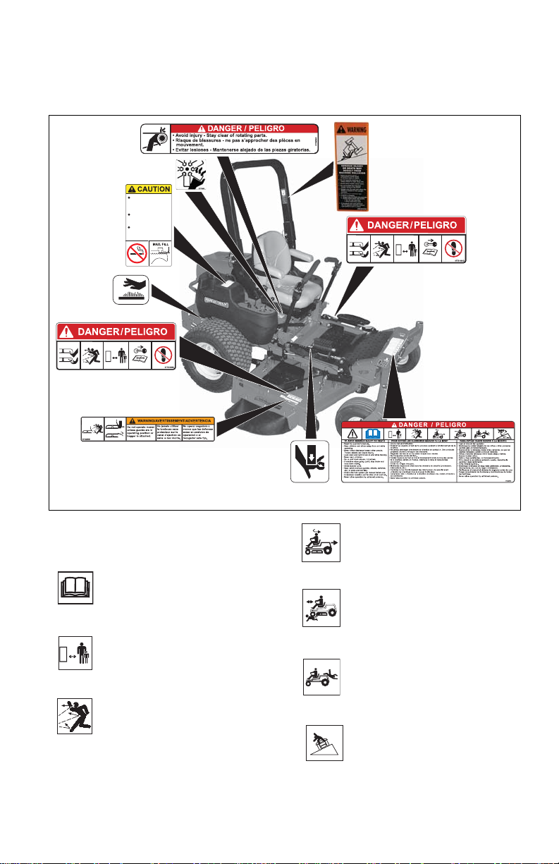
SAFETY DECALS AND
Figure 2
1
2
4
3
7
5
8
4
9
6
OL1801
OL4370
OL0910
OL4460
OL4470
OL4480
17°
MAX
OL4450
LOCATIONS
ALWAYS replace missing or damaged safety
decals. Refer to figure 2 for Safety Decal
locations.
Never fill tank when
engine is running,
hot or unit is indoors.
Never overfill fuel
tank.
Replace fuel cap
securely and clean
up spilled fuel.
08000611
1. DANGER! TO AVOID SERIOUS
INJURY OR DEATH
Read Operator’s Manual.
Keep children and others away
from unit while operating.
Never direct discharge toward
other people. Thrown objects
can cause injury.
GB - 5
Look down and behind before
and while backing.
Keep children out of work area
and under watchful care of a
responsible adult.
NEVER CARRY CHILDREN.
Go up and down slopes, not
across.
DO NOT operate on slopes
over 17°.

• If machine stops going uphill, stop
OL4900
OL4430
OL3320
OL3030
OL0910
OL3292
OL4010
OL4420
OD0061
OL4740
OL4730
blade and back down slowly.
• Avoid sudden turns.
Shut off engine, remove key,
and read manual before you
adjust or repair unit.
• Keep safety devices (guards,
shields, switches, etc.) in place and
working.
• Check interlock system per manual
before use.
• Understand location and function of
all controls.
• Never allow operation by untrained
persons.
2. PINCH POINT!
Avoid pinch points.
WARNING!
3.
Always stand clear of discharge
area.
Do not operate mower unless
guards are in operating position
or bagger is attached.
NO STEP! Always keep feet
away from rotating parts.
5.HOT SURFACES!
DO NOT touch parts which are
hot from operation. ALWAYS
allow parts to cool.
6.CAUTION!
No smoking.
MAX. FILL
Fill fuel tank to bottom of neck MAXIMUM.
• Never fill fuel tank when engine is
running, hot or unit is indoors. Never
overfill fuel tank.
• Replace fuel cap securely and clean up
spilled fuel.
4. DANGER!
Always keep feet and hands
away from rotating parts.
Always stand clear of discharge
area. Do not direct discharge
toward other people.
Keep people away from unit
while operating.
7. DANGER!
DANGER!
8.
GB - 6
AVOID INJURY. Stay clear of
rotating fan.
AVOID INJURY. Stay clear of
rotating parts.

9. WARNING!
OL3521
SERIOUS INJURY OR
DEATH MAY RESULT FROM
MACHINE ROLLOVER
• Failure to follow these
instructions could result in
serious injury or death
• Do not operate machine on
steep slopes or near drop
offs
• Avoid sharp and/or quick
turns
• Do not exceed the machine
weight rating of the ROPS
• Always use the seat belt
when the ROPS is locked in
the upright position
• Do not jump if machine tips
• If ROPS is foldable:
– Always keep the ROPS
fully exteneded
– WHEN ROPS MUST BE
DOWN -
• Do not use seat belt
• Drive with extra care
• If equipped with seat
platform,
Do not operate machine
without seat platform pins in
place
EMISSION CONTROL SYSTEM
This equipment and/or its engine may include
exhaust and evaporative emissions control
system components required to meet U.S.
Environmental Protection Agency (EPA)
and/or California Air Resources Board
(CARB) regulations. Tampering with
emission controls and components by
unauthorized personnel may result in severe
fines or penalties. Emission controls and
components can only be adjusted by an
Ariens Company dealer or an authorized
engine manufacturer's service center.
Contact your Ariens Company Equipment
Retailer concerning emission controls and
component questions.
SAFETY RULES
Read, understand, and follow all safety
practices in Owner/Operator Manual before
beginning assembly. Failure to follow
instructions could result in personal injury
and/or damage to unit.
ALWAYS remove key and/or wire from spark
plug before assembly. Unintentional engine
start up can cause death or serious injury.
Complete a walk around inspection of unit
and work area to understand:
• Work area • Your unit • All safety decals
Determine which attachments are needed
and can be used safely.
Inspect unit before each use for: missing or
damaged decals and shields, correctly
operating safety interlock system, and
deterioration of grass catchers. Replace or
repair as needed.
ALWAYS check overhead and side
clearances carefully before operation.
ALWAYS be aware of traffic when operating
along streets or curbs.
Keep children and people away.
Keep children out of work area and under
watchful care of a responsible adult.
Keep area of operation clear of all toys, pets,
and debris. Thrown objects can cause injury.
Check for weak spots on docks, ramps or
floors. Avoid uneven work areas and rough
terrain. Stay alert for hidden hazards or traffic.
DO NOT operate near drop-offs, ditches, or
embankments. Unit can suddenly turn over if
a wheel is over the edge of a cliff or ditch, or if
an edge caves in.
Data indicates that operators, age 60 and
above, are involved in a larger percentage of
riding mower related injuries. These
operators should evaluate their ability to
operate the riding mower safely enough to
protect themselves and others from serious
injury.
Read the entire Owner/Operator manual and
other training material. If the operator or the
mechanic cannot read the manual, it is the
owner’s responsibility to explain it to them.
Only the user can prevent and is responsible
for accidents or injuries occurring to
themselves, other people or property.
Only trained adults may operate or service
unit. Training includes actual operation.
Local regulations may restrict the age of the
operator.
NEVER allow children to operate or play on
or near unit. Be alert and shut off unit if
children enter area.
NEVER operate unit after or during the use of
medication, drugs or alcohol. Safe operation
requires your complete and unimpaired
attention at all times.
GB - 7

DO NOT wear loose clothing or jewelry and
tie back hair that may get caught in rotating
parts.
Wear adequate outer garments.
NEVER wear open sandals or canvas shoes
during operation. Wear adequate safety gear,
protective gloves and footwear.
Wear proper footwear to improve footing on
slippery surfaces.
Always wear safety goggles or safety glasses
with side shields when operating mower.
Moving parts can cut or amputate fingers or a
hand. Wrap blade(s) or wear gloves to
service. On multiblade mowers, rotation of
one blade will cause all blades to rotate.
NEVER place your hands or any part of your
body or clothing inside or near any moving
part while unit is running.
ALWAYS keep hands and feet away from all
rotating parts during operation. Rotating parts
can cut off body parts.
ALWAYS keep body and hands away from
pin holes or nozzles which eject hydraulic
fluid under pressure.
DO NOT touch parts which are hot. Allow
parts to cool.
ALWAYS keep hands and feet away from all
pinch points.
Fumes from the engine exhaust can cause
death or serious injury. DO NOT run engine in
an enclosed area. Always provide good
ventilation.
Read, understand, and follow all instructions
in the manual and on the machine before
starting.
Understand:
How to operate all controls
The functions of all controls
How to STOP in an Emergency
Braking and steering characteristics
Turning radius and clearances
Keep safety devices or guards in place and
functioning properly. NEVER modify or
remove safety devices.
Do not operate without either entire grass
catcher or the discharge guard in place.
Stop engine before removing grass catcher or
unclogging chute.
Ensure Safety Interlock System is functioning
properly. DO NOT operate unit if safety
interlock is damaged or disabled.
Start and operate unit only when seated in
operator’s position. Steering control levers
must be in neutral, PTO disengaged and
parking brake set when starting engine.
Use care when approaching blind corners,
shrubs, trees or other objects that may
obscure vision.
Dust, smoke, fog, etc. can reduce vision and
cause an accident. Mow only in daylight or
good artificial light.
Avoid slippery surfaces. Always be sure of
your footing.
DO NOT mow on wet grass. Reduced
traction could cause sliding and effect the
machine’s stability.
Watch for traffic when operating near or
crossing roadways.
Never carry passengers.
DO NOT try to stabilize the machine by
putting your foot on the ground.
Never direct discharge towards persons or
property that may be injured or damaged by
thrown objects. Use extreme caution on
gravel surfaces.
Always stand clear of the discharge area.
ALWAYS disengage PTO, stop unit and
engine, remove key, engage parking brake
and allow moving parts to stop before leaving
operator’s position.
Never engage PTO while raising attachment
or when attachment is in raised position.
DO NOT operate at too fast a rate. DO NOT
change engine governor settings or overspeed engine. Slow down before turning.
DO NOT operate in reverse unless absolutely
necessary. ALWAYS look down and behind
before and while backing.
Stop and inspect equipment if you strike an
object or if there is an unusual vibration.
Repair, if necessary, before restarting. Never
make adjustments or repairs with the engine
running.
Mower blades are sharp and can cut you.
Wrap the blade(s) or wear gloves, and use
extra caution when servicing them. NEVER
weld or straighten mower blades.
Rotation of one blade may cause rotation of
the other blades.
Take all possible precautions when leaving
unit unattended. Shut off engine. Remove
wire from spark plug and secure it away from
spark plug.
ALW A YS remove key to prevent unauthorized
use.
Know the weight of loads. Limit loads to those
you can safely control and the unit can safely
handle.
GB - 8

Disengage PTO when attachment is not in
use. ALWAYS turn off power to attachment
when travelling, crossing driveways, etc.
Operation on slopes may lead to loss of
steering control. When operating on slopes
be prepared to react to an emergency
situation:
• Return steering levers to neutral
position.
• Immediately set parking brake.
• Turn off PTO and engine.
Mow up and down slopes, not across them.
DO NOT operate on slopes of more than 17
degrees.
Keep all movements on the slope slow and
gradual. Do not make sudden changes in
speed or direction.
Avoid starting or stopping on the slope. If tires
lose traction, disengage the blades and
proceed slowly straight down the slope.
If you cannot back up a slope or you feel
uneasy on it, do not mow it.
DO NOT park on slopes unless necessary.
When parking on slope always chock or block
wheels. Always set parking brake.
Use a slow speed. Tires may lose traction on
slopes even though the brakes are
functioning properly.
Do not bypass transmission when on a slope.
Tow only with a machine that has a hitch
designed for towing. Do not attach towed
equipment except at the hitch point.
Follow the manufacturer’s recommendations
for weight limits for towed equipment and
towing on slopes.
On slopes, the weight of the towed equipment
may cause loss of control.
NEVER allow children or others in or on
towed equipment.
Travel slowly and allow extra distance to stop.
Rollover Protection Structure (ROPS) safety
precautions:
• Frequently inspect ROPS and seat
belt for damage or loose hardware.
• Use extreme care when working close
to fences, ditches, or on hills.
• Check overhead clearance carefully
before driving under any objects.
• ALWAYS wear seat belt while
operating the unit with the ROPS in
the upright position.
• Do not wear a seat belt while
operating the unit with the center bar
in the lowered position.
• Do not weld, cut, drill or modify ROPS
in any manner unless instructed by the
manufacturer.
Use extra care when loading or unloading
unit onto trailer or truck.
Secure unit chassis to transport vehicle.
NEVER secure from rods or linkages that
could be damaged.
DO NOT transport machine while engine is
running.
ALWAYS turn off power to attachment and
shut off fuel when transporting unit.
Keep unit free of debris. Clean up oil or fuel
spills.
This product is equipped with an internal
combustion type engine. DO NOT use unit on
or near any unimproved, forest-covered or
brush covered land unless exhaust system is
equipped with a spark arrester meeting
applicable local, state or federal laws. A spark
arrester, if it is used, must be maintained in
effective working order by operator.
Fuel is highly flammable and its vapors are
explosive. Handle with care. Use only an
approved gasoline container with an
appropriately sized dispensing spout.
NO smoking, NO sparks, NO flames.
ALWAYS allow engine to cool before
servicing.
NEVER fill fuel tank when engine is running
or hot from operation.
NEVER fill or drain fuel tank indoors.
Replace fuel cap securely and clean up
spilled fuel.
Properly remove fuel before tipping unit.
Never fill containers inside a vehicle or on a
truck or trailer bed with a plastic liner. Always
place containers on the ground away from
your vehicle before filling.
When practical, remove gas-powered
equipment from the truck or trailer and refuel
it on the ground. If this is not possible, then
refuel such equipment on a trailer with a
portable container, rather than from a
gasoline dispenser nozzle.
Keep the nozzle in contact with the rim of the
fuel tank or container opening at all times until
fueling is complete. Do not use a nozzle lockopen device.
If fuel is spilled on clothing, change clothing
immediately.
Avoid Electric Shock. Objects contacting both
battery terminals at the same time may result
in injury and unit damage. DO NOT reverse
battery connections.
GB - 9

Reverse connections may result in sparks
which can cause serious injury. Always
connect positive (+) lead of charger to
positive (+) terminal, and negative (-) lead to
negative (-) terminal.
ALW A YS disconnect negative (-) cable FIRST
and positive (+) cable SECOND. ALWAYS
connect positive (+) cable FIRST, and
negative (-) cable SECOND.
Explosive Gases from battery can cause
death or serious injury. Poisonous battery
fluid contains sulfuric acid and its contact with
skin, eyes or clothing can cause severe
chemical burns.
No flames, No sparks, No smoking near
battery.
ALWAYS wear safety glasses and protective
gear near battery. Use insulated tools.
DO NOT TIP battery beyond a 45° angle in
any direction.
ALWAYS keep batteries out of reach of
children.
Battery posts, terminals and related
accessories contain lead and lead
compounds, chemicals known to the State of
California to cause cancer and reproductive
harm. Wash hands after handling.
ALWAYS block wheels and know all jack
stands are strong and secure and will hold
weight of unit during maintenance.
Release pressure slowly from components
with stored energy.
ASSEMBLY
WARNING: AVOID INJURY . Read
and understand entire Safety
section before proceeding.
Unpack Unit
Remove unit and all other components from
shipping container. Open bypass valves (see
Moving Unit Manually on page 19). Push unit
from container onto a level surface. Close
bypass va lves.
Raise Rollover Pro tection Str ucture
(ROPS) Center Bar
See Rollover Protection Structure (ROPS) on
page 16.
NEVER attempt to make any adjustments to
unit while engine is running (except where
specifically recommended). Stop engine,
remove key or spark plug wire and wait for all
moving parts to stop before servicing or
cleaning.
Check parking brake operation frequently.
Adjust and service as required.
ALWAYS maintain unit in safe operating
condition. Damaged or worn out muffler can
cause fire or explosion.
Maintain or replace safety and instruction
labels, as necessary.
NEVER store unit with fuel in fuel tank, inside
a building where any ignition sources are
present.
Shut off fuel and allow engine to cool
completely before storing in closed area or
covering unit.
Clean grass and debris from unit, especially
from around muffler and engine, to help
prevent fires.
For extended storage, shut off fuel and clean
unit thoroughly. See engine manual for proper
storage.
Lower cutting deck unless a positive
mechanical lock is used.
Use only attachments or accessories
designed for your unit.
Check all hardware at regular intervals,
especially blade attachment bolts. Keep all
hardware properly tightened.
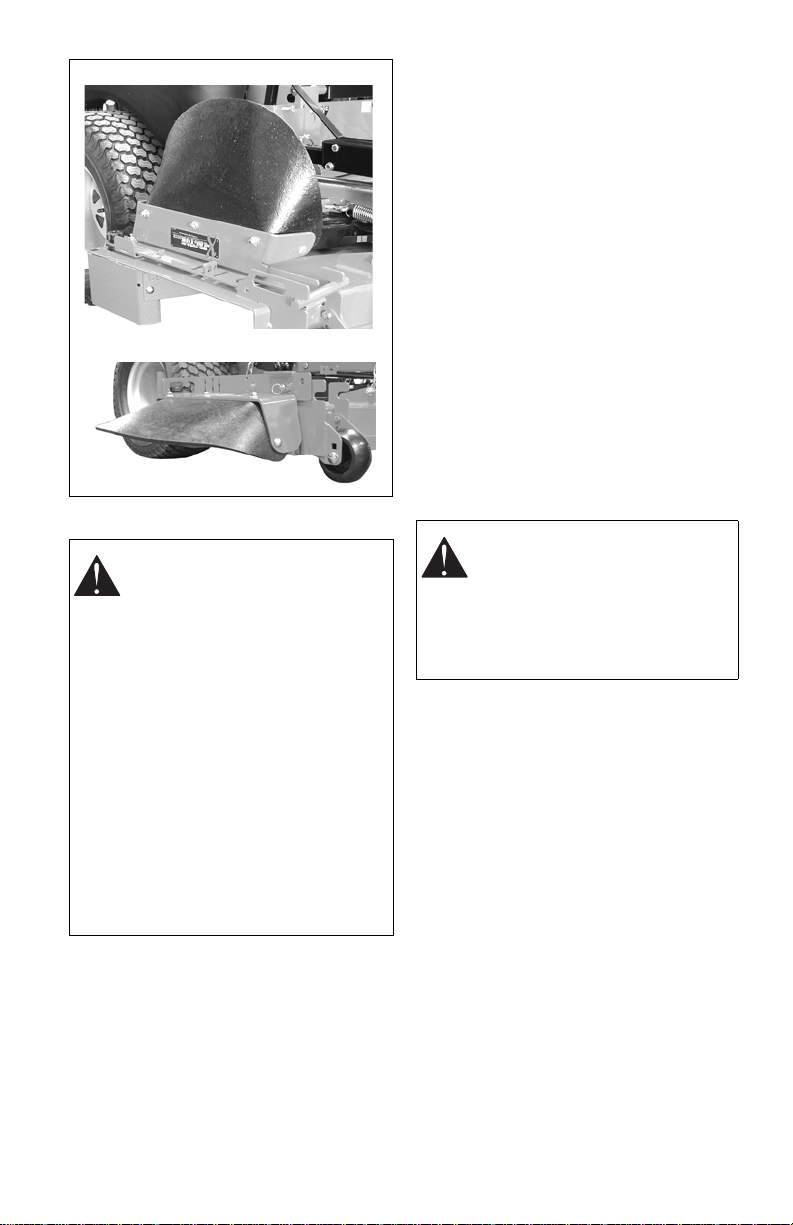
Place Discharge Chute
in Operating Position
(Figure 3)
WARNING: Do not operate
mower unless the discharge chute
is in the operating position.
Prior to operating the unit, remove the
discharge chute from the transport position
and place the discharge chute in the
operating position .
GB - 10
Check Tire Pressure
Figure 3
Discharge Chute in Transport Position
Discharge Chute in Operating Position
CAUTION: Avoid injury! Explosive
separation of tire and rim parts is
possible when they are serviced
incorrectly:
• Do not attempt to mount a tire
without the proper equipment
and experience to perform the
job.
• Do not inflate the tires above
the recommended pressure.
• Do not weld or heat a wheel
and tire assembly. Heat can
cause an increase in air
pressure resulting in an
explosion. Welding can
structurally weaken or deform
the wheel.
• Do not stand in front or over the
tire assembly when inflating.
Use a clip-on chuck and
extension hose long enough to
allow you to stand to one side.
Check Engine Oil
Refer to Engine Manual.
Check Hydraulic Oil
See Checking Hydraulic Oil Level on
page 33.
Check Coolant Level (992215, 216)
Refer to Engine Manual.
Fill Fuel T ank
Fill fuel tank. DO NOT OVERFILL! See Filling
Fuel Tank on page 16.
Connect Battery
Place unit in the service position (see Service
Position on page 22). Connect negative (–)
battery cable to battery (see Battery
Installation (Figure 10) on page 23 and
perform steps 2 through 4 in the installation
section).
Check Blade Level and Blade Pitch
See Leveling the Mower Deck on page 26.
Check Safety Interlock System
WARNING: Safety in terlock
system failure and improper
operation of unit can result in
death or serious injury. Test this
system each time unit is operated.
If this system does not function as
described, do not operate until
repairs are made.
See Safety Interlock System on page 13.
Check Function of All Controls
Ensure unit runs and performs properly.
See Specifications on page 39.
GB - 11
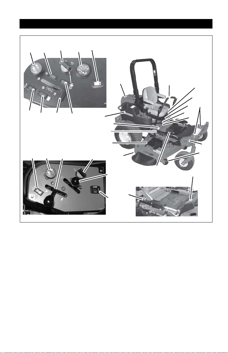
CONTROLS AND FEATURES
Figure 4
1
18
3
4, 5
7
2
8
9
13
16
17
15
19
21
27
22
25
Control Panel for Models 992215, 216
Control Panel for Models
922210, 212, 213, 217
19
21
25
20
26
28
11
23
23
27
12, 14
24
29
10
11
992210, 212
6
15
1. Hood
2. Parking Brake Lever
3. Steering Levers
4. Mower Lift Lever (992213, 215, 216,
217)
5. Seat Adjustment Lever (Front/Back)
6. Seat Suspension Adjustment Knob
7. Fuel Shut-Off Valve
8. Axle Locks
9. Tie-Down Lugs
10. Mower Lift Pedal (992210, 212)
11. Height of Cut Indicator
12. Cylinder Stops (992213, 215, 216, 217)
13. Anti-Scalp Rollers
14. Cylinder Stop Storage Post
(992213, 215, 216, 217)
15. Foot Board Latch
16. Mower Deck with Chute Deflector
17. Belt Cover
18. Fuel Tanks
19. PTO (Power Take-Off) Switch
20. Glow Plug Light (992215, 216)
21. Ignition Switch
22. Coolant Temperature Gauge
(992215, 216)
23. Hour Meter
24. Charging System Light (992215, 216)
25. Throttle Lever
26. Fuel/Water Separator Light
(992215, 216)
27. Oil Pressure Light
28. Choke Control
(922210, 212, 213, 217)
29. Seat Release Knob (Tilt)
GB - 12

WARNING: AVOID INJURY . Read
1
2
3
2
1
1
2
and understand entire Safety
section before proceeding.
CONTROLS AND FEATURES
See figure 4 for Controls and Features
locations.
Safety Interlock System
WARNING: Safety interlock
system failure and improper
operation of unit can result in
death or serious injury. Test this
system each time the unit is
operated. If this system does not
function as described, do not
operate until repairs are made.
OPERATION
Ignition Switch
Operate the ignition
switch with the
removable key. The
switch has three
positions: Off ( 1 ) , Ru n
(2) and Start (3). See
Starting And Shutting Off
Engine on page 18 for
detailed instructions on how to start engine.
Choke Con trol (922210, 212, 213, 217)
Use to start a cold engine.
Push choke lever forward
to start a cold engine. Pull
the choke lever to the rear
when the engine is warm.
Throttle Lever
Changes the speed of engine.
Perform the following tests to ensure the
safety interlock system is working properly. If
the unit does not perform as stated, contact
your Gravely dealer for repairs.
IMPORTANT: With the parking brake
engaged, the steering levers must be locked
in neutral.
IMPORTANT: With the parking brake
disengaged, the engine must not start and
the engine must shut off if the operator leaves
the seat.
Test Steering
Levers
STARTING INTERLOCK
1 Neutral Off Engaged Starts
2 Neutral On Engaged Doesn’t
3 Neutral Off
OPERATING INTERLOCK (ENGINE ON)
4* Neutral On Engaged Shuts Off
5* Neutral Off
6* Neutral Off Engaged On
* Operator lifts off seat.
PTO Parking
Brake
Disengaged
Disengaged
Engine
Start
Doesn’t
Start
Shuts Off
Fast (1) – Increases
engine speed.
Slow (2) – Decreases
engine speed.
Power Take Off (PTO) Switch
Engages (1) and
disengages (2) mower
blades.
GB - 13
°F
170
195
220
280
100
40
80 100
140
WATER
TEMP
°C
Display
Toggle Button
RIGHT
TANK
LEFT
TANK
OFF
1
2
3
1
3
2
4
Oil Pressure Light
Indicates when engine oil
pressure is low.
NOTE: It does not
indicate engine oil level.
See Troubleshooting on
page 35 or refer to Engine
Manual for details.
Charging System Light (992215, 216)
Indicates when the charging system is not
charging the battery.
Glow Plug Light (992215, 216)
Indicates when the engine glow plugs are
energized. Glow plugs energize for
approximately 5 seconds when the key
switch is turned to the Run position.
Fuel / Water Separator Light
(992215, 216)
Indicates when the fuel/water separator filter
needs to be replaced (refer to Engine
Manual).
Coolant T e mpe rature Gauge
(992215, 216)
Indicates temperature
of coolant. See
Troubleshooting on
page 35 or refer to
Engine Manual for
details.
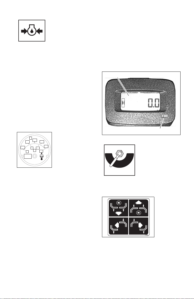
Hour Meter
Press and release the toggle button to shift
between different functions.
Press and hold the toggle button to reset the
timer or clear a service message.
The hour meter has three functions:
Hour Meter: measures the amount of time
the engine has been run. This time cannot be
cleared.
Timer (TMR1): measures the time spent on
individual jobs.
Press and hold the toggle button to reset the
timer to zero. TMR1 will then start measuring
engine run time until it is reset to zero again.
Service Alert (Chg Oil, Chg H Oil & Filter,
SVC Airfilter): reminds operators of the
maintenance interval for changing the engine
oil, changing the hydraulic oil and filter and
servicing the air filter.
The alert starts counting down two hours
before the maintenance is due. The meter
flashes the word, "Now," when it reaches the
maintenance time.
Press and hold the toggle button to reset the
maintenance clock to zero after perfoming
the service.
NOTE: The hour meter is preprogrammed for
the initial oil change at 25 hours and for 100
hours thereafter. The hour meter is
programmed for the initial hydraulic oil and
filter change at 75 hours and for 400 hours
thereafter.
Fuel Shut-Off Valve
Controls fuel flow from
left fuel tank (1) or right
fuel tank (2).
Open valve to operate
the engine. Turn the
valve to off (3) when
storing or transporting
the unit.
NOTE: There is no off (3) position on models
992215, 216.
Steering Levers
Control
speed,
directional
control, and
stopping unit.
•Reverse (1)
– Pull both
steering
levers
backward.
GB - 14
• Forward (2) – Push both steering
levers forward.
• Left (3) – Pull left steering lever back
or push right steering lever forward or
a combination of both.
• Right (4) – Pull right steering lever
back or push left steering lever
forward or a combination of both.
 Loading...