

Gravely 988001-060, 988001-063, 988001-007, 988001-059, 988001-069 Service Manual
...
Pro 100/150/200
Service Manual
Models 988001-007, 059, 060, 062, 063, 069-072, 074, 075,
077-082, 085, 087, 088, 309
08484000 06/00
Printed in USA

TABLE OF CONTENTS
Section 1 - Introduction . . . . . . . . . . . . . . . . . . 1-3
1.1 The Manual. . . . . . . . . . . . . . . . . . . . . . . . . 1-3
1.2 Service And Replacement Parts. . . . . . . . . 1-3
1.3 Product Registration. . . . . . . . . . . . . . . . . . 1-3
1.4 Unauthorized Replacement Parts. . . . . . . . 1-3
1.5 Disclaimer. . . . . . . . . . . . . . . . . . . . . . . . . . 1-3
1.6 Technical Service Communications . . . . . . 1-3
Section 2 - Safety. . . . . . . . . . . . . . . . . . . . . . . . 2-4
2.1 Safety Alerts . . . . . . . . . . . . . . . . . . . . . . . . 2-4
2.2 Signal Words. . . . . . . . . . . . . . . . . . . . . . . . 2-4
2.3 Notations. . . . . . . . . . . . . . . . . . . . . . . . . . . 2-4
2.4 Practices And Laws . . . . . . . . . . . . . . . . . . 2-4
2.5 Required Operator Training . . . . . . . . . . . . 2-4
2.6 Preparation . . . . . . . . . . . . . . . . . . . . . . . . . 2-4
2.7 Cleaning And Storage. . . . . . . . . . . . . . . . . 2-4
2.8 Safety Rules . . . . . . . . . . . . . . . . . . . . . . . . 2-4
2.9 Clean Unit. . . . . . . . . . . . . . . . . . . . . . . . . . 2-6
Section 3 - Specifications . . . . . . . . . . . . . . . . . 3-7
Section 4 - General Maintenance
& Adjustments . . . . . . . . . . . . . . . . . . . . . 4-12
4.1 Controls And Features . . . . . . . . . . . . . . . 4-12
4.2 Check Fuel Level . . . . . . . . . . . . . . . . . . . 4-12
4.3 General Lubrication . . . . . . . . . . . . . . . . . 4-14
4.4 Checking Fasteners . . . . . . . . . . . . . . . . . 4-14
4.5 Check Tires. . . . . . . . . . . . . . . . . . . . . . . . 4-14
4.6 The Steering Levers . . . . . . . . . . . . . . . . . 4-14
4.7 The Steering Lever Latches . . . . . . . . . . . 4-14
4.8 Adjusting The Levers . . . . . . . . . . . . . . . . 4-15
4.9 Adjusting The Shift Lever . . . . . . . . . . . . . 4-15
4.10 Adjusting The PTO Clutch . . . . . . . . . . . 4-16
4.11 Adjusting The Roller Chain . . . . . . . . . . . 4-17
Section 5 - Engine . . . . . . . . . . . . . . . . . . . . . . 5-18
5.1 Engine Troubleshooting . . . . . . . . . . . . . . 5-18
5.2 Checking Engine Oil. . . . . . . . . . . . . . . . . 5-19
5.3 Changing Oil Filter . . . . . . . . . . . . . . . . . . 5-19
5.4 Air Cleaner . . . . . . . . . . . . . . . . . . . . . . . . 5-19
5.5 Check Spark Plug. . . . . . . . . . . . . . . . . . . 5-19
5.6 Engine Removal . . . . . . . . . . . . . . . . . . . . 5-19
5.7 Engine Installation . . . . . . . . . . . . . . . . . . 5-19
Section 6 - Steering And Controls . . . . . . . . . .6-20
6.1 Steering Controls . . . . . . . . . . . . . . . . . . . 6-20
6.2 Operator Presence Control. . . . . . . . . . . . 6-20
Section 7 - Drive Train . . . . . . . . . . . . . . . . . . . 7-21
7.1 Troubleshooting . . . . . . . . . . . . . . . . . . . . 7-21
7.2 transmission . . . . . . . . . . . . . . . . . . . . . . . 7-21
7.3 Transmission Removal . . . . . . . . . . . . . . . 7-21
7.4 Replacing The Transmission Belt . . . . . . . 7-21
7.5 Traction Clutch . . . . . . . . . . . . . . . . . . . . . 7-22
7.6 Replacing The Traction Belts . . . . . . . . . . 7-23
7.7 Replacing The Pto Clutch Belt . . . . . . . . . 7-24
7.8 Electric Clutch. . . . . . . . . . . . . . . . . . . . . . 7-25
7.9 Wheel Removal. . . . . . . . . . . . . . . . . . . . . 7-25
Section 8 - Fuel System. . . . . . . . . . . . . . . . . . .8-26
8.1 Fuel System Troubleshooting . . . . . . . . . . 8-26
8.2 Fuel Pump. . . . . . . . . . . . . . . . . . . . . . . . . 8-26
8.3 Fuel System Contamination . . . . . . . . . . . 8-26
8.4 Fuel Tank . . . . . . . . . . . . . . . . . . . . . . . . . 8-26
Section 9 - Electrical . . . . . . . . . . . . . . . . . . . . .9-27
9.1 Tools . . . . . . . . . . . . . . . . . . . . . . . . . . . . . 9-27
9.2 Electrical Measurements. . . . . . . . . . . . . . 9-27
9.3 Battery. . . . . . . . . . . . . . . . . . . . . . . . . . . . 9-28
9.4 Switches . . . . . . . . . . . . . . . . . . . . . . . . . . 9-30
9.5 Solenoid And Relays. . . . . . . . . . . . . . . . . 9-31
9.6 Lighting Circuits . . . . . . . . . . . . . . . . . . . . 9-32
9.7 Fuses . . . . . . . . . . . . . . . . . . . . . . . . . . . . 9-32
9.8 Diodes And Rectifiers . . . . . . . . . . . . . . . . 9-32
9.9 Electric Clutch. . . . . . . . . . . . . . . . . . . . . . 9-32
9.10 Checking The PTO Clutch . . . . . . . . . . . 9-32
9.11 Interlock Switch. . . . . . . . . . . . . . . . . . . . 9-33
9.12 Fuse Holder . . . . . . . . . . . . . . . . . . . . . . 9-33
9.13 Pro 200 Check-out . . . . . . . . . . . . . . . . . 9-33
9.14 Continuity Diagrams . . . . . . . . . . . . . . . . 9-37
9.15 Wiring Diagram . . . . . . . . . . . . . . . . . . . . 9-41
9.16 Electrical System . . . . . . . . . . . . . . . . . . 9-44
2
SECTION 1 - INTRODUCTION
1.1 THE MANUAL
The purpose of this manual is to provide complete
instructions for service, maintenance, disassembly,
repair, and installation of the mechanical components
for the unit.
Dealer trained service personnel should use this
manual as a supplement to and reminder of the training
sessions conducted by the company.
Read all information for servicing a part or system
before repair work is started to avoid needless
disassembly.
Operation
Before operation of the unit, carefully and completely
read manuals supplied with the unit. The contents will
provide you with an understanding of safety
instructions and controls during normal operation and
maintenance.
Safety Messages
For your safety and the safety of others always read,
understand, and follow all DANGER, WARNING, and
CAUTION messages found in manuals and on safety
decals.
Directional Reference
All reference to left, right, front, or rear are given from
the operator in the operator position and facing the
direction of forward travel.
1.2 SERVICE AND REPLACEMENT PARTS
When ordering publications, replacement parts, or
making service inquiries, know the Model and Serial
numbers of your unit and engine.
Numbers are located on the product registration form in
the unit literature package. They are printed on a serial
number label, located on the frame of your unit.
Serial Number
1.3 PRODUCT REGISTRATION
A warranty registration card must be filled out, signed,
and returned at time of purchase. This card activates
the warranty. Claims meeting requirements during
limited warranty period will be honored.
1.4 UNAUTHORIZED REPLACEMENT
PARTS
Use only Gravely replacement parts. The replacement
of any part on this vehicle with anything other than a
Gravely authorized replacement part may adversely
affect the performance, durability, or safety of this unit
and may void the warranty. Gravely disclaims liability
for any claims or damages, whether warranty, property
damage, personal injury , or death arising out of the use
of unauthorized replacement parts.
1.5 DISCLAIMER
Gravely reserves the right to discontinue, make
changes to, and add improvements upon its products
at any time without public notice or obligation. The
descriptions and specifications contained in this
manual were in effect at printing. Equipment described
within this manual may be optional. Some illustrations
may not be applicable to your unit.
1.6 TECHNICAL SERVICE
COMMUNICATIONS
Gravely Technical Service communicates information
to the field using Service Letters, Service Bulletins,
Product Notices, and Campaigns. Each
communication signifies a type of information and
priority. The dealer is responsible to carry out the
directive provided in the communication. The types of
communication are:
Service Letter
dealer. Technical information on how to service the
product and product improvements.
Service Bulletin
resolve certain issues or a notification of a policy
change.
Product Notices
located in a certain region. This is a limited distribution
to only those who received the product involved.
Campaigns
products must be updated and are tracked by the
factory until all units are corrected.
- General technical information for the
- Notification to update products to
- Notification of limited product
- Notification of a safety related issue. All
Figure 1
1 - 3
SECTION 2 - SAFETY
2.1 SAFETY ALERTS
Look for these symbols to point out
important safety precautions. They
mean:
Attention!
Personal Safety Is Involved!
Become Alert!
Obey The Message!
2.2 SIGNAL WORDS
The safety alert symbol is used in decals on the unit
and with proper operation procedures in this manual.
They alert you to the existence and relative degree of
hazards.
Understand the safety message. It contains important
information about personal safety on or near the unit.
DANGER:
SITUATION! If not avoided, WILL RESULT in
death or serious injury.
WARNING:
SITUATION! If not avoided, COULD RESULT
in death or serious injury .
CAUTION:
SITUATION! If not avoided, MAY RESULT in
minor or moderate injury. It may also be used
to alert against unsafe practices.
IMMINENTLY HAZARDOUS
POTENTIALLY HAZARDOUS
POTENTIALLY HAZARDOUS
2.3 NOTATIONS
NOTE:
ation and maintenance practices.
IMPORTANT:
required to prevent damage to unit or attachment.
General reference information for proper oper-
Specific procedures o r infor mati on
2.4 PRACTICES AND LAWS
Practice usual and custo mar y safe worki ng
precautions, for the benefit of yourself and others.
Understand and follow all safety messages. Be alert to
unsafe conditions and the possibility of minor,
moderate, or serious injury or death. Learn applicable
rules and laws in your area.
2.5 REQUIRED OPERATOR TRAINING
Original purchaser of this unit was instructed by the
seller on safe and proper operation. If unit is to be used
by someone other than original purchaser; loaned,
rented or sold, AL WAYS provide the Operator’s Manual
and any needed safety training before operation.
2.6 PREPARATION
Before starting any removal of parts, proper
preparation is very important for efficient work. A clean
work area at the start of each job will allow you to
perform service repairs easily and quickly.
To reduce the incidence of misplaced tools or parts,
place removed components with all attaching hardware
in the disassembly order on a clean work surface.
Organization is a key part of proper reassembly.
T ools, instruments, and parts needed for the job should
be gathered before work is started. Interrupting a job to
locate tools or parts is a needless delay. A list of
required special tools has been included in this
manual.
CAUTION:
spillage will occur. Remove battery to prevent
spillage of electrolyte.
Remove enough fuel so that no
2.7 CLEANING AND STORAGE
IMPORTANT:
outdoors.
A unit that is excessively dirty should be cleaned
before work starts. Cleaning will occasionally uncover
trouble sources. Dirt and abrasive dust reduce the
efficient work life of parts and can lead to costly
replacement.
When taking unit out of extended storage:
1. Check for any damage or loose parts. Repair
replace, or tighten hardware before operation.
2. If a preservative fluid was used in fuel tank, drain
and discard. Fill fuel tank with fresh new fuel.
Never spray unit with water or store unit
2.8 SAFETY RULES
Walk Around Inspection
Complete a walk around inspection of unit and work
area to understand:
• Work area.
• Your unit.
• All safety decals.
Work Are a
ALWAYS check overhead and side clearances
carefully before operation. ALWAYS be aware of traffic
when operating along streets or curbs.
ALWAYS keep hands and feet within the limits of the
unit.
Keep children, people, and animals away. Keep
children out of work area and under watchful care of a
responsible adult.
2 - 4

Keep area of operation clear of all toys, pets, and
debris. Objects can cause vehicle instability and injury.
Check for weak spots on dock, ramps or floors. Avoid
uneven work areas and rough terrain. Stay alert for
hidden hazards.
DO NOT run engine in an enclosed area. Always
provide good ventilation.
Unit
ALWAYS keep protective structures, guards, and
panels in good condition, in place and securely
fastened. NEVER modify or remove safety devices.
Check Safety Interlock System for proper operation
daily (see Operation section). Do not operate unless
system operates properly.
Operation
Understand:
• How to operate all controls
• The functions of all controls
• How to STOP in an Emergency
• Speed ranges
Do not operate any of the control levers or power takeoff unless both feet are resting on the platform.
DO NOT travel at too fast a rate. DO NOT change
engine governor settings or over-speed engine.
Always back up slowly. Always look down and behind
before and while backing.
Never leave a running unit unattended. ALWAYS shut
off power take off, lower throttle setting, and stop
engine before leaving unit. ALWAYS remove key to
prevent unauthorized use.
Never carry passengers on any part of unit.
Avoid uneven and rough terrain. DO NOT operate near
drop offs, ditches, or embankments. Unit can suddenly
turn over if a wheel is over the edge of a cliff or ditch, or
if an edge caves in.
If tires lose traction, turn off power take off and proceed
slowly straight down slope. Avoid wet surfaces.
Avoid parking on a slope. If necessary, use wheel
chocks.
DO NOT leave unit unattended on a slope. ALWAYS
use wheel chocks when leaving unit.
ALWAYS operate unit in good visibility and light.
Fuel is highly flammable and its vapors can explode.
Use ONLY approved fuel containers.
NO Smoking!
NO Sparks!
NO Flames!
Allow engine to cool before servicing.
NEVER fill fuel tank when engine is running, hot, or unit
is indoors.
Abnormal Vibrations are a warning of trouble. Striking a
foreign object can damage unit. Immediately stop unit
and engine. Remove key and wait for all moving parts
to stop. Remove wire from spark plug. Inspect unit and
make any necessary repairs before restart.
Hazardous Slopes
DO NOT operate on steep slopes. Avoid operating on
slopes. When you must operate on a slope, travel up
and down the slope. Never operate across a slope.
Never operate on a slope greater than 10 degrees.
Child Safety
NEVER allow children to operate or play on or near
unit. Be alert and shut off unit if children enter area.
Personal Safety
Read and obey all warning, caution, and instructions
on the unit and in provided manuals.
• Only trained adults may operate unit.
• Training includes actual operation.
• Clearly understand instructions.
• Be alert! Conditions can change.
NEVER operate unit after or during the use of
medication, drugs or alcohol. Safe operation requires
your complete and unimpaired attention at all times.
NEVER allow anyone to operate the unit when their
alertness or coordination is impaired.
DO NOT operate unit without wearing adequate outer
garments. Wear adequate safety gear and protective
gloves. Wear proper footwear to improve footing on
slippery surfaces.
Protect eyes, face, and head from objects that may be
thrown from unit. Wear appropriate hearing protection.
Avoid Sharp Edges. Sharp edges can cut. Moving
parts can cut or amputate fingers or a hand. Wear
gloves to service unit when handling sharp edges.
ALWAYS keep hands away from any pinch points.
ALWAYS keep hands and feet away from all moving
parts during operation. Moving parts can cut off body
parts.
DO NOT touch unit parts which might be hot from
operation. Allow parts to cool before attempting to
maintain, adjust, or service.
Controls
Come to a complete stop before reversing.
Never jerk the control levers. Always use a steady
even action to achieve smooth control.
Always be aware of obstructions that may cause injury
to operator or damage to the unit.
2 - 5
Service Position
WARNING:
that jack stands or blocks used are stable,
strong, or secure and will hold the weight of
the unit during maintenance.
WARNING:
body parts. Keep hands and feet away. Loose
clothing, long hair or scarves can get caught
in rotating parts and cause death or serious
injury.
Place unit on flat, level surface. ALW AYS stop engine
and disengage clutches. Assure unit is secure and will
not tip over. Strap and clamp onto lift, if used.
To ensure the unit is positioned in the proper service
position:
1. Place jack stands under rear transaxles only.
2. If jacks are not available, place support blocks
under both transaxles at the rear of unit.
CAUTION:
spills will occur.
ALWAYS block wheels and know
ROTATING PARTS can amputate
Remove enough fuel so that no
meeting applicable local, state or federal laws. A spark
arrester, if used, must be maintained in effective
working order by the operator.
Battery
Avoid Electric Shock. DO NOT reverse battery
connections.
Explosive Gases! Poisonous battery fluid contains
sulfuric acid and its contact with skin, eyes, or clothing
can cause severe burns.
No flames. No sparks. No smoking near battery.
Always wear safety glasses and protective gear near
battery.
DO NOT TIP battery beyond a 45
direction.
ALWAYS KEEP BATTERIES OUT OF REACH of
children.
o
angle in any
Transport
Use extra care when loading or unloading unit onto
trailer or truck. Secure unit chassis to transport vehicle.
NEVER secure from rods or linkages that could be
damaged.
DO NOT transport with attachment in raised position.
Lower attachment when unit is parked or stored unless
a positive mechanical lock is used.
Maintenance
ALWAYS maintain unit in safe operating condition.
Damaged or worn out muffler can cause fire or
explosion.
Check the conditions of the unit at the end of each day
and repair any damage or defects.
ALWAYS block wheels and know all jack stands are
strong and secure and will hold weight of unit during
maintenance.
Keep nuts and bolts tight and keep equipment in safe
operating conditions.
Before maintenance, adjustments, or service (except
where specifically recommended), shut off engine.
Allow hot parts to cool.
Keep unit free of dirt, stones, and other debris. Clean
up oil or fuel spills.
Storage
DO NOT store unit inside a building with fuel in the fuel
tank where any ignition sources are present. Allow unit
to cool completely.
ALWAYS clean unit before extended storage. See
Engine Manual for proper storage.
Attachments and Accessories
Use only attachments or accessories designed for your
unit.
2.9 CLEAN UNIT
Brush grass, dirt and debris off of unit with a soft brush.
Clean packed grass out from under mower deck. Apply
paint or oil to exposed, bare metal surfaces to prevent
rust.
Inspect unit for visible signs of wear, breakage, or
damage. Order any parts required and make
necessary repairs to avoid delays when beginning use
again.
Clean seat regularly, using a non-solvent cleaner.
Extreme temperatures can damage seat when left
unprotected against weather. If seat should tear, apply
vinyl repair tape to protect damaged area.
Transaxle cooling fins must be kept clean to prevent
damage from overheating. Use a cloth or brush to
remove grass, chaff and debris.
Unless there are indications of leakage, transaxle does
not have to be checked for proper oil level. If leak
occurs, have it repaired by your Gravely Dealer.
Spark Arrester
This product is equipped with an internal combustion
engine. DO NOT use on or near any unimproved,
forest covered or brush covered land unless the
exhaust system is equipped with a spark arrester
2 - 6

SECTION 3 - SPECIFICATIONS
Model Type Pro 100 Pro 100 Pro 150
Model Number 988001 988002 988059
Manufacture Briggs & Stratton Kawasaki Kawasaki
Horsepower 12 HP 12.5 HP 14 HP
Engine Spec. No. 281702-902512 FB 460V AS20 FC 420V-ES 15
Fuel Unleaded Unleaded Unleaded
Fuel Tank Cap. 3 gal. (11.4L) 3 gal. (11.4L) 4.5 gal. ( 17L)
Fuel Filter P/N 040742 040742 040742
Engine Oil SAE 30 10W 30 SAE 30
Crankcase Cap. 4 pts. (1.9L) 3 pts. (1.4L) 3 pts. (1.4L)
Engine Oil Filter N/A 20777000 20777000
Governed RPM 3300 RPM 3300 RPM 3600 RPM
Air Cleaner w/Foam Precleaner N/A 042926 Paper Element
Brakes & Steering 6 " Band/Drum 6 " Band/Drum 6 " Band/Drum
Tire Size Front 13 x 5.00-6 (4 Ply) 13 x 5.00-6 (4 Ply) 13 x 6-6 (2 Ply)
Tire Pressure 12 to 15 psi 12 to 15 psi 12 tp 15 psi
Transmission Tecumseh Pro Line 700-032 Tecumseh Pro Line 700-032 Peerless 700-032
Speed-Forw. Max 5.4 mph (8.7 kph) 5.4 mph (8.7 kph) 5.2 mph (8.4 kph)
Reverse Max. Assist Assist 3 mph (4.8 kph)
Transmission Lube Sealed Sealed Sealed
Spark Plug Champion Champion Champion
Type RC19 LM RCJ-8 RN 11 YC
Spark Plug Gap 0.03 0.024-0.028 0.028-0.031
Wheel Drive Belt
(Matched Set)
Traction Drive Belt 049270 049270 04927
PTO Belt 041963 041963 N/A
07225800 07225800 07225800
Model Type Pro 150 Pro150 Pro 150
Model Number 988060 988069 988070
Manufacture Kawasaki Kohler Kohler
Horsepower 12.5 HP 14 HP 15 HP
Engine Spec. No. FB 460V-DS20 PS-1411 PS-41532
Fuel Unleaded Unleaded Unleaded
Fuel Tank Cap. 4.5 gal. (17L) 4.5 gal. (17L) 4.5 gal. (17L)
Fuel Filter P/N 040742 040742 040742
Engine Oil SAE 30 SAE 30/10W30 10W 30
Crankcase Cap. 3 pts. (1.4L) 3 pts. (1.4L) 3 pts. (1.4L)
Engine Oil Filter 20777000 N/A 042366
Governed RPM 3300 RPM 3600 RPM 3600 RPM
Air Cleaner w/Foam Precleaner Paper Element Paper Element Paper Element
Brakes & Steering 6 " Band/Drum 6 " Band/Drum 6 " Band/Drum
Tire Size Front 13 x 6-6 (2 Ply) 13 x 6-6 (4 Ply) 13 x 6-6 (4 Ply)
Tire Pressure 12 to 15 psi 12 to 15 psi 12 to 15 psi
Transmission Tecumseh Pro Line 700-032 Tecumseh Pro Line 700-032 Peerless 700-032
Speed-Forw. Max 5.2 mph (8.4 kph) 5.2 mph (8.4 kph) 5.2 mph (8.4 kph)
Reverse Max. 3 mph (4.8 kph) 3 mph (4.8 kph) 3 mph (4.8 kph)
Transmission Lube Sealed Sealed Sealed
Spark Plug Champion Cham pi on Champion
Type RN J-8 RC 12 YC RC 12 YC
Spark Plug Gap 0.024-0.028 0.04 0.04
Wheel Drive Belt
(Matched Set)
Traction Drive Belt 049270 049270 049270
PTO Belt N/A N/A N/A
07225800 07225800 07225800
3 - 7

Model Type Pro 150 Pro 150 Pro 150
Model Number 988074 988075 988077
Manufacture Kohler Kawasaki Kawasaki
Horsepower 12.5 HP 12.5 HP 14 HP
Engine Spec. No. PS-1283 FB 460V-DS20 GS01 FC 420V-ES 15
Fuel Unleaded Unleaded Unleaded
Fuel Tank Cap. 4.5 gal. (17L) 4.5 gal. (17L) 4.5 gal. (17L)
Fuel Filter P/N 040742 040742 040742
Engine Oil 10W30 SAE 30 SAE 30
Crankcase Cap. 3 pts. (1.4L) 3 pts. (1.4L) 3 pts. (1.4L)
Engine Oil Filter 042366 20777000 20777000
Governed RPM 3600 RPM 3300 RPM 3300 RPM
Air Cleaner w/Foam Precleaner Paper Element Paper Element Paper Element
Brakes & Steering 6 " Band/Drum 6 " Band/Drum 6 " Band/Drum
Tire Size Front 13 x 6.-6 (4 Ply) 13 x 6-6 (4 Ply) 13 x 6-6 (4 Ply)
Tire Pressure 12 to 15 psi 12 to 15 psi 12 to 15 psi
Transmission Peerless 700-032 Peerless 700-032 Peerless 700-032
Speed-Forw. Max 5.2 mph (8.4 kph) 5.2 mph (8.4 kph) 5.2 mph (8.4 kph)
Reverse Max. 3 mph (4.8 kph) 3 mph (4.8 kph) 3 mph (4.8 kph)
Transmis si on Lub e Sealed Sealed Sealed
Spark Plug Champion Champion Champion
Type RC 12 YC RCJ-8 RN 11 YC
Spark Plug Gap 0.040 0.024-0.028 0.028-0.031
Wheel Drive Belt
(Matched Set)
Traction Drive Belt 049270 049270 049270
PTO Belt N/A N/A N/A
07225800 07225800 07225800
Model Type Pro 150 Pro 150 Pro 150
Model Number 988078 988079 988088
Manufacture Kohler Kohler Kawasaki
Horsepower 12.5 HP 15 HP 14 HP
Engine Spec. No. PS-1283 PS-41532 FC 420V-ES 15
Fuel Unleaded Unleaded Unleaded
Fuel Tank Cap. 4.5 gal. (17L) 4.5 gal. (17L) 4.5 gal. (17L)
Fuel Filter P/N 040742 040742 040742
Engine Oil 10W 30 10W 30 SAE 30
Crankcase Cap. 3 pts. (1.4L) 3 pts. (1.4L) 3 pts. (1.4L)
Engine Oil Filter 042366 042366 20777000
Governed RPM 3300 RPM 3300 RPM 3300 RPM
Air Cleaner w/Foam Precleaner Paper Element Paper Element Paper Element
Brakes & Steering 6 " Band/Drum 6 " Band/Drum Foam Precleaner
Tire Size Front 13 x 6.00-6 (4 Ply) 13 x 6.00-6 (4 Ply) 6 " Band/Drum
Tire Pressure 12 to 15 psi 12 to 15 psi 13 x 6.00-6 (2 Ply)
Transmission Peerless 700-032 Peerless 700-032 12 to 15 psi
Speed-Forw. Max 5.2 mph (8.4 kph) 5.2 mph (8.4 kph) Peerless 700-079
Reverse Max. 3 mph (4.8 kph) 3 mph (4.8 kph) 5.2 mph (84 kph)
Transmission Lube Sealed Sealed 3 mph (4.8 kph)
Spark Plug Champion Champion Sealed
Type RC 12 YC RC 12 YC Champion
Spark Plug Gap 0.04 0.04 RN 11 YC
Wheel Drive Belt
(Matched Set)
Traction Drive Belt 049270 049270 07225800
PTO Belt N/A N/A N/A
07225800 07225800 0.028-0.031
3 - 8

Model Type Pro 150 Pro 150 Pro 200
Model Number 988091 988309 988003
Manufacture Kawasaki Kawasaki Kawasaki
Horsepower 12.5 HP 10.9 HP 12.5 HP
Engine Spec. No. FB 460V DS20 GS01 FC 420V ES15 FB 460V AS20
Fuel Unleaded Unleaded Unleaded
Fuel Tank Cap. 4.5 gal. (17L) 4.5 gal. (17L) 3 gal. (11.4L)
Fuel Filter P/N 040742 040742 040742
Engine Oil SAE 30 SAE 30 SAE 30
Crankcase Cap. 3 pts. (1.4L) 3 pts. (1.4L) 3 pts. (1.4L)
Engine Oil Filter 20777000 20777000 20777000
Governed RPM 3300 RPM 2950 RPM 3300 RPM
Air Cleaner w/Foam Precleaner Paper Element Paper Element Paper Element
Brakes & Steering Foam Precleaner 6 " Band/Drum 6 " Band/Drum
Tire Size Front 6 " Band/Drum 13 x 6.50-6 (4 Ply) 13 x 6.50-6 (4 Ply)
Tire Pressure 13 x 6.00-6 (4 Ply) 12 to 15 psi 12 to 15 psi
Transmission 12 to 15 psi Tecumseh Pro Line 700-079 Tecumseh Pro Line 700-052
Speed-Forw. Max Peerless 700-079 5.2 mph (8.4 kph) 5.4 mph (8.7 kph)
Reverse Max. 5.2 mph (8.4 kph) 3 mph (4.8 kph) 1.8 mph (2.9 kph)
Transmission Lube 3 mph (4.8 kph) Sealed Sealed
Spark Plug Sealed Champion Champion
Type Champion RN 11 YC RCJ-8
Spark Plug Gap RCJ - 8 0.028-0.031 0.024 - 0.028
Wheel Drive Belt
(Matched Set)
Traction Drive Belt 07225800 049270 052776
PTO Belt N/A N/A 07225000
0.024-0.028 07225800 049029
Model Type Pro 200 Pro 200 Pro 200
Model Number 988004 988005 988006
Manufacture Kohler Kohler Kawasaki
Horsepower 14 HP 16 HP 17 HP
Engine Spec. No. PS - 1411 PS - 56518 FC 540V AS04
Fuel Unleaded Unleaded Unleaded
Fuel Tank Cap. 3 gal. (11.4L) 3 gal. (11.4L) 3 gal. (11.4L)
Fuel Filter P/N 040742 040742 040742
Engine Oil 10W 30 10W 30 SAE 30
Crankcase Cap. 4 pts. (1.9L) 4 pts. (1.9L) 3 pts. (1.4L)
Engine Oil Filter 042366 042366 20777000
Governed RPM 3300 RPM 3300 RPM 3300 RPM
Air Cleaner w/Foam Precleaner Paper Element Paper Element Paper Element
Brakes & Steering 6 " Band/Drum 6 " Band/Drum 6 " Band/Drum
Tire Size Front 13 x 6.50-6 (4 Ply) 13 x 6.50-6 (4 Ply) 13 x 6.50-6 (4 Ply)
Tire Pressure 12 to 15 psi 12 to 15 psi 12 to 15 psi
Transmission Tecumseh Pro Line 700-052 Tecumseh Pro Line 700-052 Tecumseh Pro Line 700-052
Speed-Forw. Max 5.4 mph (8.7 kph) 5.4 mph (8.7 kph) 5.4 mph (8.7 kph)
Reverse Max. 1.8 mph (2.9 kph) 1.8 mph (2.9 kph) 1.8 mph (2.9 kph)
Transmission Lube Sealed Sealed Sealed
Spark Plug Champion Champion Champion
Type RC 12 YC RC 12 YC RN 11 YC
Spark Plug Gap 0.04 0.035 0.028-0.031
Wheel Drive Belt
(Matched Set)
Traction Drive Belt 052776 052776 052776
PTO Belt 07225000 07225000 07225000
049029 049029 049029
3 - 9

Model Type Pro 200 Pro 200 Pro 200
Model Number 988007 988062 988063
Manufacture Kohler Kawasaki Briggs & Stratton
Horsepower 18 HP 14 HP 16 HP
Engine Spec. No. PS - 58516 FC 420V AS15 303777 - 0138
Fuel Unleaded Unleaded Unleaded
Fuel Tank Cap. 3 gal. (11.4L) 3.5 gal. (13.3L) 3.5 gal. (13.3L)
Fuel Filter P/N 040742 040742 040742
Engine Oil 10W 30 SAE 30 SAE 30/10W30
Crankcase Cap. 4 pts. (1.9L) 3.4 pts. (1.4L) 4 pts. (1.9L)
Engine Oil Filter 042366 20777000 N/A
Governed RPM 3300 RPM 3300 RPM 3600 RPM
Air Cleaner w/Foam Precleaner Paper Element Paper Element Paper Element
Brakes & Steering 6 " Band/Drum 6 " Band/Drum 6 " Band/Drum
Tire Size Front 13 x 6.50-6 (4 Ply) 13 x 6.50-6 (4 Ply) 13 x 6.50-6 (4 Ply)
Tire Pressure 12 to 15 psi 12 to 15 psi 12 to 15 psi
Transmission Tecumseh Pro Line 700-052 Tecumseh Pro Line 700-052 Tecumseh Pro Line 700-052
Speed-Forw. Max 5.4 mph (8.7 kph) 5.4 mph (8.7 kph) 5.4 mph (8.7 kph)
Reverse Max. 1.8 mph (2.9 kph) 1.8 mph (2.9 kph) 1.8 mph (2.9 kph)
Transmission Lube Sealed Sealed Sealed
Spark Plug Champion Champion Champion
Type RC 12 YC RN 11 YC RC 14 YC
Spark Plug Gap 0.035 0.028-0.031 0.03
Wheel Drive Belt
(Matched Set)
Traction Drive Belt 052776 052776 052776
PTO Belt 07225000 07225000 07225000
Battery 041358 041358 041358
049029 049029 049029
Model Type Pro 200 Pro 200 Pro 200
Model Number 988071 988072 988080
Manufacture Kohler Kohler Kohler
Horsepower 15 HP 18 HP 15 HP
Engine Spec. No. PS-41532 PS61527 CV 15T PS-41532
Fuel Unleaded Unleaded Unleaded
Fuel Tank Cap. 3.5 gal. (13.3L) 3.5 gal. (13.3L) 3.5 gal. (13.3L)
Fuel Filter P/N 040742 040742 040742
Engine Oil 10W 30 10W 30 10W 30
Crankcase Cap. 4 pts. (1.9L) 2.1 pts. (2L) 4 pts. (1.9L)
Engine Oil Filter 042366 042366 042366
Governed RPM 3300 RPM 3300 RPM 3300 RPM
Air Cleaner w/Foam Precleaner Paper Element Paper Element Paper Element
Brakes & Steering 6 " Band/Drum 6 " Band/Drum 6 " Band/Drum
Tire Size Front 13 x 6.50-6 (4 Ply) 13 x 6.50-6 (4 Ply) 13 x 6.50-6 (4 Ply)
Tire Pressure 12 to 15 psi 12 to 15 psi 12 to 15 psi
Transmission Tecumseh Pro Line 700-052 Tecumseh Pro Line 700-052 Tecumseh Pro Line 700-052
Speed-Forw. Max 5.4 mph (8.7 kph) 5.4 mph (8.7 kph) 5.4 mph (8.7 kph)
Reverse Max. 1.8 mph (2.9 kph) 1.8 mph (2.9 kph) 1.8 mph (2.9 kph)
Transmission Lube Sealed Sealed Sealed
Spark Plug Champion Champion Champion
Type RC 12 YC RC 12 YC RC 12 YC
Spark Plug Gap 0.04 0.03 0.04
Wheel Drive Belt
(Matched Set)
Traction Drive Belt 052776 052776 052776
PTO Belt 07225000 07225000 07225000
Battery 041358 041358 041358
049029 049029 049029
3 - 10

Model Type Pro 200 Pro 200 Pro 200
Model Number 988081 988082 988085
Manufacture Briggs & Stratton Kohler Robin
Horsepower 16 HP 18 HP 18 HP
Engine Spec. No. 303777-0138 CV 18S PS-61527 EH 63 V
Fuel Unleaded Unleaded Unleaded
Fuel Tank Cap. 3.5 gal. (13.3L) 3.5 gal. (13.3L) 3.5 gal. (13.3L)
Fuel Filter P/N 040742 040742 040742
Engine Oil SAE/10W 30 10W 30 10W 30
Crankcase Cap. 4 pts. (1.9L) 2.1 pts. (2L) 4 pts. (1.9L)
Engine Oil Filter N/A 042366 21527000
Governed RPM 3600 RPM 3300 RPM 3300 RPM
Air Cleaner w/Foam Precleaner Paper Element Paper Element Paper Element
Brakes & Steering 6 " Band/Drum 6 " Band/Drum 6 " Band/Drum
Tire Size Front 13 x 6.50-6 (4 Ply) 13 x 6.50-6 (4 Ply) 13 x 6.00-6 (2 Ply)
Tire Pressure 12 to 15 psi 12 to 15 psi 12 to 15 psi
Transmission Tecumseh Pro Line 700-052 Tecumseh Pro Line 700-052 Tecumseh Pro Line 700-052
Speed-Forw. Max 5.4 mph (8.7 kph) 5.4 mph (8.7 kph) 5.4 mph (8.7 kph)
Reverse Max. 1.8 mph (2.9 kph) 1.8 mph (2.9 kph) 1.8 mph (2.9 kph)
Transmission Lube Sealed Sealed Sealed
Spark Plug Champion Champion NGK
Type RC 14 YC RC 12 YC Part # 21526900
Spark Plug Gap 0.03 0.03 0.03
Wheel Drive Belt
(Matched Set)
Traction Drive Belt 052776 052776 052776
PTO Belt 07225000 07225000 07225000
Battery 041358 041358 041358
049029 049029 049029
Model Type Pro 200
Model Number 988087
Manufacture Kawasaki
Horsepower 14 HP
Engine Spec. No. FC 420V-ES 15
Fuel Unleaded
Fuel Tank Cap. 3.5 gal. (13.3L)
Fuel Filter P/N 040742
Engine Oil SAE 30
Crankcase Cap. 4 pts. (1.9L)
Engine Oil Filter 20777000
Governed RPM 3300 RPM
Air Cleaner w/Foam Precleaner Paper Element
Brakes & Steering 6 " Band/Drum
Tire Size Front 13 x 6.00-6 (2 Ply)
Tire Pressure 12 to 15 psi
Transmission Tecumseh Pro Line 700-052
Speed-Forw. Max 5.4 mph (8.7 kph)
Reverse Max. 1.8 mph (2.9 kph)
Transmission Lube Sealed
Spark Plug Champion
Type RN 11 YC
Spark Plug Gap 0.028-0.031
Wheel Drive Belt
(Matched Set)
Traction Drive Belt 052776
PTO Belt 7225000
Battery 041358
049029
3 - 11
SECTION 4 - GENERAL MAINTENANCE & ADJUSTMENTS
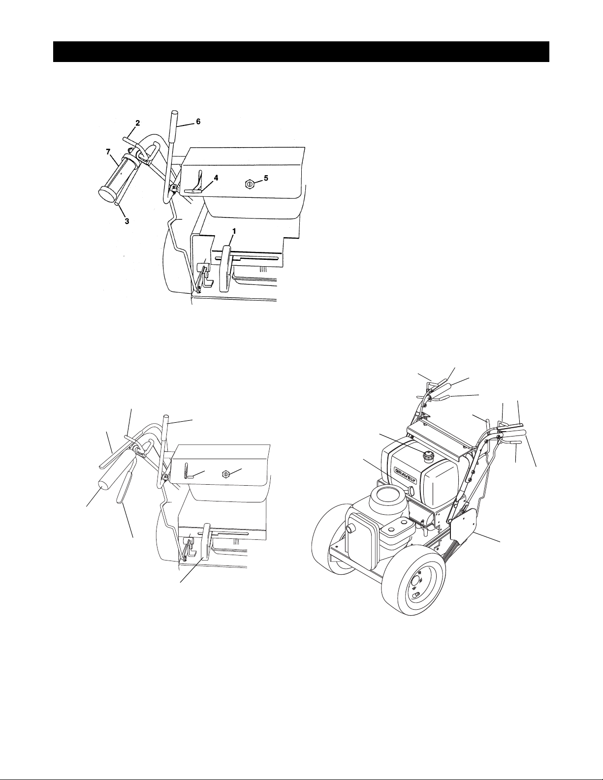
4.1 CONTROLS AND FEATURES
Pro 100
1. Shift Lever
2. Steering Lever Latch
3. Steering Lever
4. Throttle-Choke Lever
5. Ignit ion Switch
6. PTO Lever
7. Operator Presence Controls
Figure 2 - Pro 100
11
2
2
7
3
6
4
1
5
Pro 150
8
9
OG0741
7
11
3
6
7
2
3
11
10
OG1131
1. Shift Lever
2. Steering Lever Latches
3. Steering Levers
4. Throttle-Choke Lever
5. Ignition Switch
6. PTO Lever
7. Operator Presence Controls
8. Fuel Cap
9. Recoil Starter Handle
10.Traction Belt Guard
Figure 3 - Pro 150
4 - 12
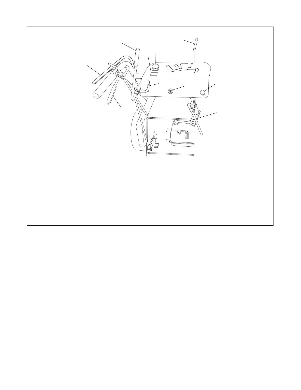
Pro 200
6
2
7
9
10
1
3
1. Shift Lever
2. Steering Lever Latch
3. Steering Lever
4. Throttle-Choke Lever
5. Ignition Switch
6. PTO Lever (recoil start models)
7. Operator Presence Control
4
8. Transmission Shifter Rod
9. PTO Switch (electric start models)
10. Hour Meter (electric start models)
11. Choke Control (electric start models)
Figure 4 - Pro 200
5
11
8
4 - 13
4.2 FILLING THE FUEL TA NK
WARNING:
flammable. Keep fuel in a clean and tight
container. Keep fuel away from fire and heat.
Never put fuel in the fuel tank while the engine
is running or hot. Clean up any spilled fuel
before starting the engine.
Add fuel to the fuel tank as needed. See your engine
manual for the correct type and grade of fuel to be
used.
1. Put the unit in an open and well ventilated area
prior to refueling.
2. Stop the engine.
3. Allow the engine to cool.
4. Clean the fuel cap and in the area around the fuel
cap. Remove the cap from the fuel tank.
5. Fill the fuel tank with the proper grade of fuel
recommended by the engine manufacturer. Be
careful not to spill any fuel.
6. Install fuel cap on the fuel tank and tighten.
7. Clean up any spilled fuel before starting engine.
Use caution with fuel. Fuel is very
4.3 GENERAL LUBRICATION
Apply a small amount of oil to the pivot points as
required for smooth and proper operation.
Every 8 hours of operation, add Sten Mix Hi-Temp
Grease or equivalent to the lube fittings, in each of the
wheel hubs. After every 8 hours of operation, apply a
small amount of oil to the drive chain.
4.4 CHECKING FASTENERS
Each day before operating, check all nuts, bolts, and
other fasteners. Replace fasteners that are missing or
damaged.
4.5 CHECK TIRES
Keep tires properly inflated at all times. The correct air
pressure is 12 to 15 psi 83 to 103 kN/m
2
. After
checking and/or inflating, replace and tighten valve
caps to prevent air loss.
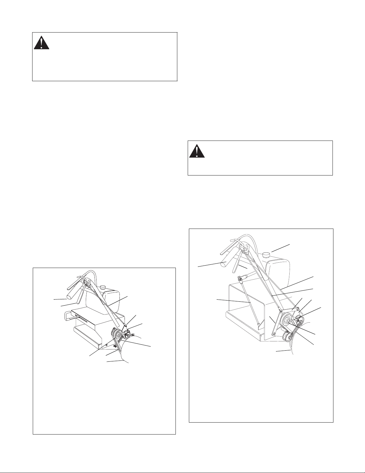
4.6 THE STEERING LEVERS
The steering levers are used to steer the unit. Pull up
on the left hand lever to turn to the left. Pull up on the
right lever to turn to the right. Holding both levers up
stops the unit. See Figures 5 and 6.
WARNING:
When the engine is running and
transmission is in gear, holding only one
steering lever up will cause the unit to circle
around one drive wheel.
4.7 THE STEERING LEVER LATCHES
The steering lever latches are used to hold the steering
levers in the up position. Engaging both steering lever
latches will free one of the operator’s hands for a
throttle adjustment, etc. (see Figures 2 and 3).
10
1
2
6
1. Handlebar
2. Steering Lever
3. Wheel Clutch
Actuating Rod
4. Wheel Clutch Arm
Weldment
5. Brake Rod
8
9
Figure 5
3
4
5
7
6. Transmission Shaft
Pulley
7. Clutch Idler Pulley
Spring
8. Traction Belt (Pro 200
shown - Pro 100 has
one belt)
9. Drive Wheel
OG0751
1
11
1. Handlebar
2. Steering Lever
3. Brake Rod
4. Clutch Rod
5. Jack-Shaft Pulley
6. Clutch Actuating Strap
7. Traction Belt
Figure 6 - Pro 200
2
3
4
6
12
7
6
8
9
8. Clutch Idler Pulley
Spring
9. Drive Wheel
10. Fuel Cap
11. Clutch Actuating Rod
12. Wheel Clutch Arm
Weldment
5
4 - 14
 Loading...