

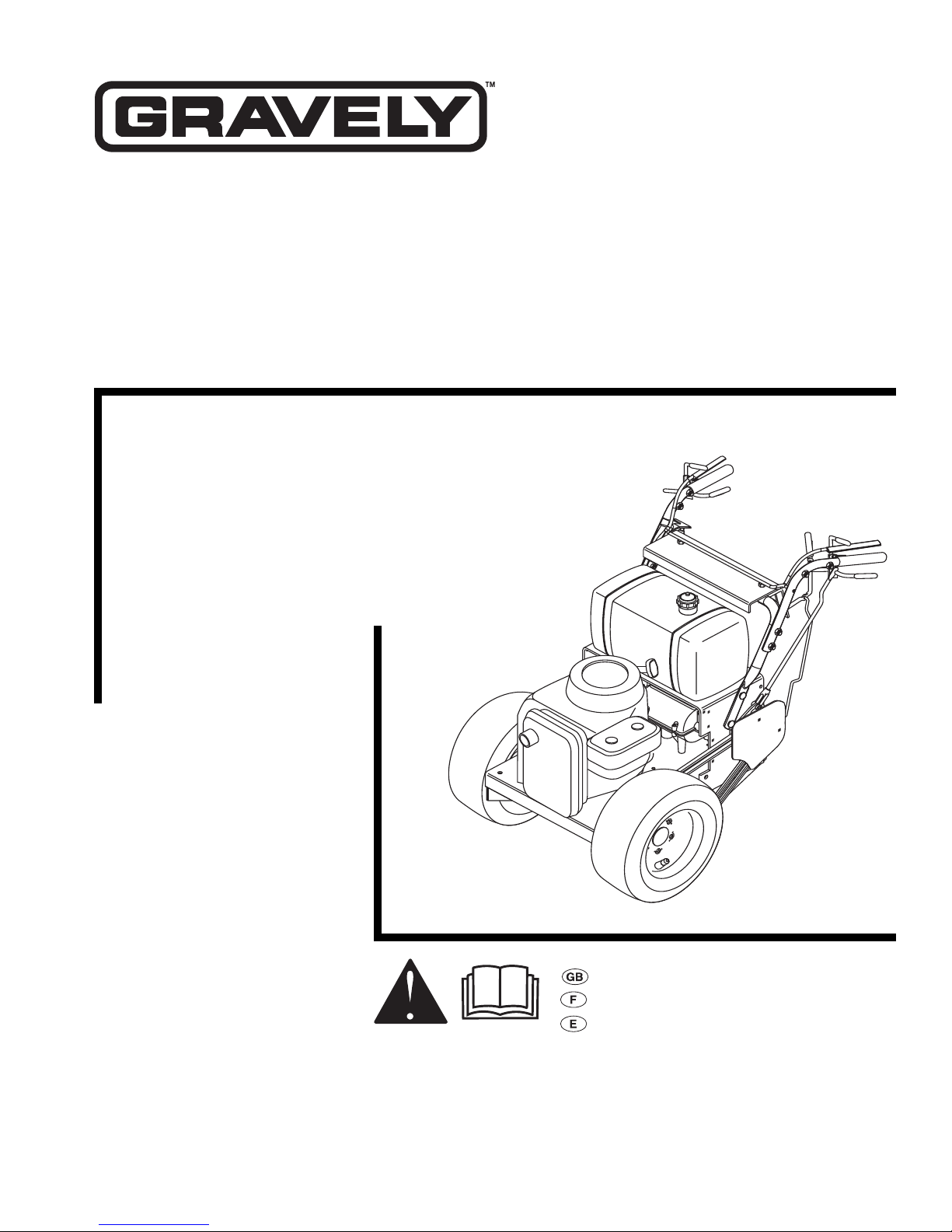
Pro 150
Owner/Operator Manual
Model
988088
988091
988092
988309
ENGLISH
FRANÇAIS
ESPAÑOL
08478400A 10/00
Supercedes 08478400
Printed in USA

Ariens Company
655 West Ryan Street
P.O. Box 157
Brillion, Wisconsin 54110-0157
U.S.A.
Telephone (920) 756-2141
Facsimile (920) 756-2407
MODEL CERTIFICATE OF CONFORMITY ISSUED BY THE MANUFACTURER
CERTIFICAT DE CONFORMITÉ DU MODÈLE DÉLIVRÉ PAR LE FABRICANT
MODELL-KONFORMITÄTSBESTÄTIGUNG AUSGESTELLT DURCH DEN HERSTELLER
MODELCERTIFICAAT VAN OVEREENSTEMMING AFGEGEVEN DOOR DE FABRIKANT
CERTIFICATO DI COMFORMITÀ DEL MODELLO RILASCIATO DAL PRODUTTORE
CERTIFICADO DE CONFORMIDAD DEL MODELO PROVISTO POR EL FABRICANTE
MODEL KONFORMITETS ERKLÆRING UDSTEDT AF FABRIKANTEN
MODELLSERTIFIKAT FOR OVERENSSTEMMELSE UTSTEDT AV FABRIKANT TILLVERKERENS
TILLVERKARENS MODELLCERTIFIKAT OM ÖVERENSSTÄMMELSE
VALMISTAJAN ANTAMA VAKUUTUS MALLIN MÄÄRÄYSTEN MUKAISUUDESTA
We the undersigned, - Je soussigné, - Mit meiner Unterschrift - De ondergetekende, - Il sottoscritto, - El abajo firmante,
Undertegnede, - Undertecknaren av detta dokument, - Me, allekirjoittaneet,
ARIENS COMPANY, certify that the riding rotary lawnmower - certifie que les tondeuse rotative autoportée - bestätige ich, daß der
Mäher - verklaart dat de Grasmaaimachine - certifica che le i trattorino con unità di taglio rotativa - certifica que el Cortacésped
giratorio para pasajeros - certificamos que o minitractor cortador de grama com lâminas giratórias - bevidner herved at Selvkørende
rotations græsslåmaskine - bevitner at gressklippertraktor - intygar att intygar att åkrotorklippare - vakuutamme, että lumilinko
Ajoleikkuri:
Category: WIDE-AREA COMMERCIAL
Make and Trade Name: GRA
Model:
988309 with 888301
VELY
WALK-BEHIND ROTARY MOWER
Serial # Range: From – To 000101 – 000999
conform to the specifications of directive 98/37/EC, and council directive 84/538/EEC as amended by 87/252/EEC, 83/180/EEC and 88/181/EEC,
and EC directive (EMC) 89/336/EEC as amended by EC directive 92/31/EEC.
sont conformes aux spécifications de la directive 98/37/EEC et la directive du conseil Européen numéro 84/538/EEC révisée par les directives 87/
252/EEC, 83/180/EEC et 88/181/EEC et de la directive EC (EMC) 89/336/EEC modifiée par la directive EC 92/31/EEC.
den Spezifikationen der Direktive 98/37/EEC, sowie der Ratsdirektive 84/538/EEC, modifiziert durch die Direktiven 87/252/EEC, 83/180/EEC und
88/181/EEC, sowie der EU-Direktive (EMC) 89/336/EEC, modifiziert durch die EU-Directive 92/31/EEC, entspricht.
in overeenstemming zijn met de specificaties van richtlijn 98/37/EEG, en richtlijn 84/538/EEG van de raad, zoals gewijzigd door 87/252/EEG, 83/
180/EEG en 88/181/EEG, en EC richtlijn (EMC) 89/336/EEC zoals gewijzigd door EC richtlijn 92/31/EEC.
sono conformi alla direttiva CEE 98/37 e alla direttiva del Consiglio Europeo CEE 84/538, emendata dalle direttive CEE 87/252, 83/180 e 88/181, e
la direttiva CE (EMC) CEE 89/336, emendata dalla direttiva CEE 92/31.
conforme a las especificaciones de la directiva 98/37/CEE, y la directiva del consejo europeo número 84/538/CEE modificada en las directivas 87/
252/CEE, 83/180/CEE y 88/181/CEE, y la directiva EC (EMC) 89/336/EEC reformada por la directiva EC 92/31/EEC.
opfylder specifikationerne i direktiv 98/37/EEC og rådets direktiv 84/538/EEC med ændringer i 87/252/EEC, 83/180/EEC og 88/181/EEC, og EC direktiv
(EMC) 89/336/EEC med ændringer i EC direktiv 92/31/EEC.
Enheten oppfyller spesifikasjonene i direktiv 98/37/EEC og rådets direktiv 84/538/EEC med endringer i 87/252/EEC, 83/180/EEC og 88/181/EEC, og
EC direktiv (EMC) 89/336/EEC med endringer i EC direktiv 92/31/EEC.
är i överensstämmelse med specifikationerna i direktiv 98/37/EEC, samt rådsdirektiv 84/538/EEC, med ändringar i 87/252/EEC, 83/180/EEC och 88/
181/EEC, och EC direktiv (EMC) 89/336/EEC med ändringar i EC direktiv 92/31/EEC.
On valmistettu 98/37/EEC, mukään. Ja neuvostori määräysten, 84/538/EEC tarkennettu 87/252/EEC, 83/180/EEC ja 88/181/EEC mukaan, ja EC
määräysten (EMC) 89/336/EEC tarkennettu määräysten EC 92/31/EEC mukaan.
Certifiying Laboratory to 84/538/EEC - TUV Rheinland.
F
ebruary 1, 1999
Date/Datum/Data/
Fecha/Dato/Päiväys
Manufacturers of Printed in U.S.A. 10-00
Outdoor Power Equipment
Manager of Product Conf
Position/Qualité/Stilling/Functie/Qualifica/
Puesto/Stilling/Funktie/Titel/Arvo
ormance
Signature/Unterschrift/Handtekening/Firma/
Underskrift/Underskrift Handlekening/
Underskrift/Allekirjoitus
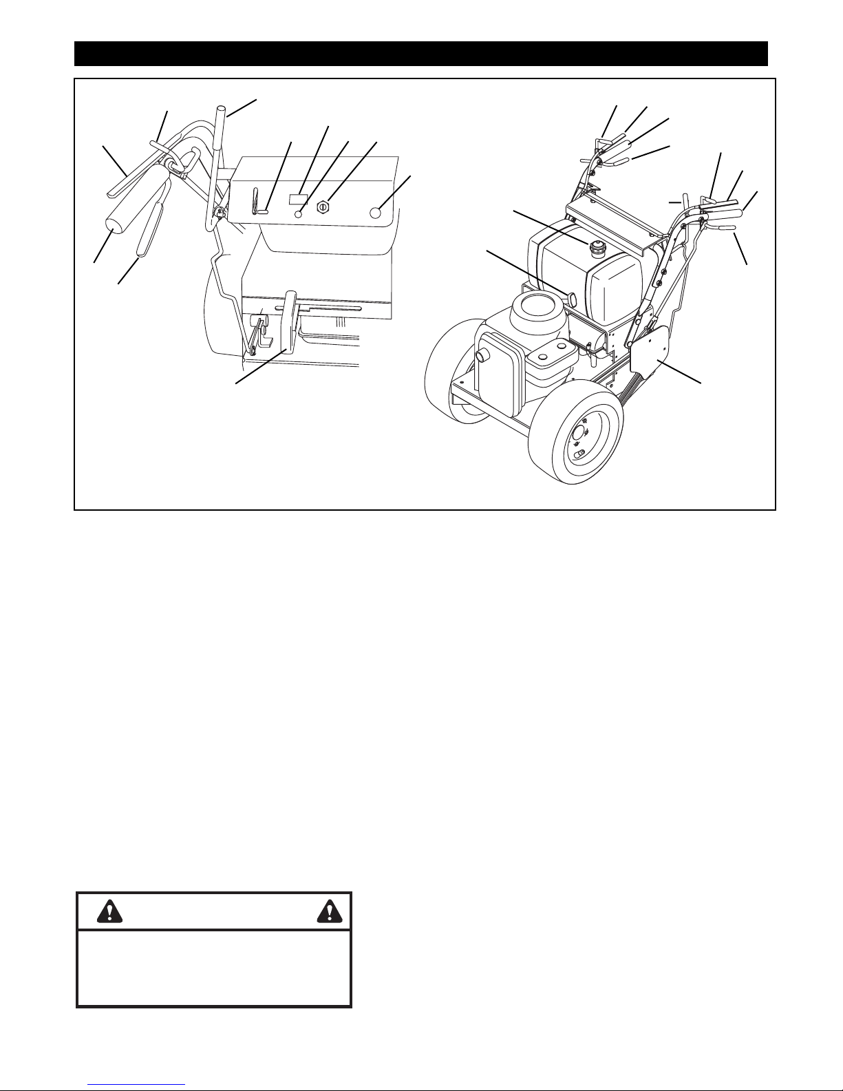
CONTROLS AND FEATURES
11
2
6
13
7
4
14
5
2
7
11
3
2
7
12
11
8
6
9
3
3
1
OG0741
Figure 1
10
OG1131
ENGLISH
1. Shift Lever
2. Steering Lever Latches
3. Steering Levers
4. Throttle-Choke Lever
5. Ignition Switch
6. PTO Lever
7. Operator Presence
Controls
8. Fuel Cap
9. Recoil Starter Handle
10. Traction Belt Guard
11. Handlebar
12. Choke Control (Electric
Start Models)
13. Hourmeter (Electric Start
Models)
14. Oil Light (Electric Start
Models)
WARNING
FRANÇAIS
1. Levier de vitesses
2. Verrouillage des poignées
de direction
3. Leviers de direction
4. Manette des gaz – Starter
5. Clé de contact
6. Commande de la PdF
7. Commandes de présence
de l’opérateur
8. Bouchon du réservoir
de carburant
9. Poignée du démarreur
à cordon
10. Garant de courroie
de transmission
11. Guidon
12. Commande du starter
(Modèles à démarreur
électrique)
13. Compteur horaire
(Modèles à démarreur
électrique)
14. Voyant de l’huile
(Modèles à démarreur
ESPAÑOL
1. Palanca de cambios
2. Trabas de las palancas
de la dirección
3. Palancas de dirección
4. Palanca del aceleradorestrangulador
5. Interruptor de encendido
6. Palanca de la TDF
7. Controles de presencia
del operador
8. Tapón del combustible
9. Manilla de arranque de
retroceso
10. Protección de la correa
de tracción
11. Manillar
12. Control de
estrangulamiento
(modelos con
arranque eléctrico)
13. Batería (modelos de
arranque eléctrico)
14. Luz del aceite (modelos
de arranque eléctrico)
The engine exhaust from this product
contains chemicals known to the State
of California to cause cancer, birth
defects or other reproductive harm.
OL4030
3
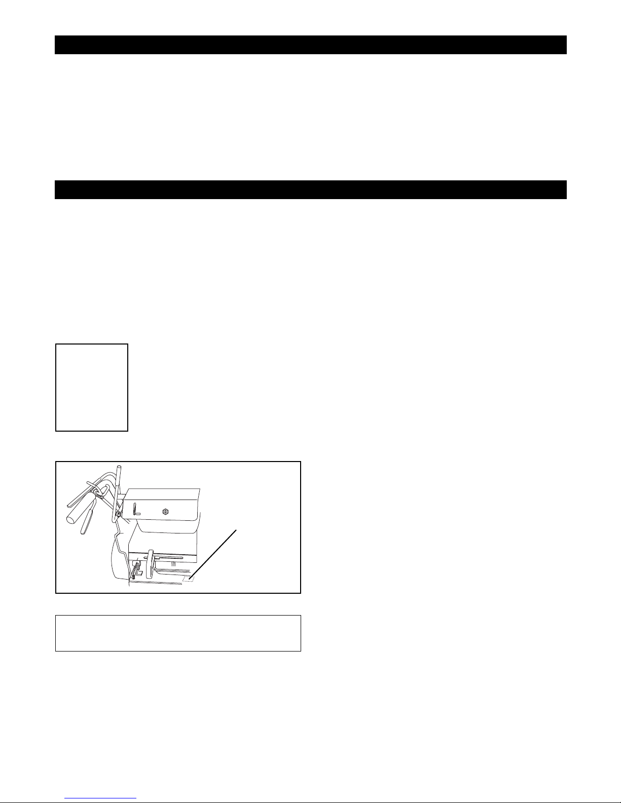
TABLE OF CONTENTS
Controls and Features. . . . . . . . . . . . . . . . . . . . . 3
Introduction . . . . . . . . . . . . . . . . . . . . . . . . . . . . . 4
Safety . . . . . . . . . . . . . . . . . . . . . . . . . . . . . . . . . . 5
Assembly . . . . . . . . . . . . . . . . . . . . . . . . . . . . . . . 8
Operation . . . . . . . . . . . . . . . . . . . . . . . . . . . . . . . 8
Maintenance . . . . . . . . . . . . . . . . . . . . . . . . . . . . 12
Service and Adjustments . . . . . . . . . . . . . . . . . 13
INTRODUCTION
THE MANUAL
Before operation of unit, carefully and completely read
your manuals. The contents will provide you with an
understanding of safety instructions and controls
during normal operation and maintenance.
All reference to left, right, front, or rear are given from
operator standing in operation position and facing the
direction of forward travel.
MODEL AND SERIAL NUMBERS
When ordering replacement parts
Transfer
model & serial
number label
from product
registration
here.
• Record Engine Model and Serial numbers here.
or making service inquiries, know
the Model and Serial numbers of
your unit and engine.
Numbers are located on the product
registration form in the unit literature
package. They are also printed on a
serial number label, located on the
frame of your unit.
Serial
Number
Label
OG1031
Storage . . . . . . . . . . . . . . . . . . . . . . . . . . . . . . . . 17
Troubleshooting . . . . . . . . . . . . . . . . . . . . . . . . . 17
Accessories and Attachments . . . . . . . . . . . . . 18
Service Parts . . . . . . . . . . . . . . . . . . . . . . . . . . . 18
Specifications. . . . . . . . . . . . . . . . . . . . . . . . . . . 19
Warranty . . . . . . . . . . . . . . . . . . . . . . . . . . . . . . . . 20
UNAUTHORIZED REPLACEMENT PARTS
Use only Gravely replacement parts. The replacement
of any part on this vehicle with anything other than a
Gravely authorized replacement part may adversely
affect the performance, durability, or safety of this unit
and may void the warranty. Gravely disclaims liability
for any claims or damages, whether warranty, property
damage, personal injury or death arising out of the use
of unauthorized replacement parts.
DISCLAIMER
Gravely reserves the right to discontinue, make
changes to, and add improvements upon its products
at any time without public notice or obligation.The
descriptions and specifications contained in this
manual were in effect at printing. Equipment described
within this manual may be optional. Some illustrations
may not be applicable to your unit.
DEALER DELIVERY
Dealer should:
1. Check all controls for proper function.
2. Check the safety interlock system to make sure
that it is functioning properly. (See Operation .)
3. Fill out Original Purchaser Registration Card and
return the card to Gravely.
4. Explain Limited Warranty Policy.
5. Explain recommended lubrication and
maintenance. Advise customer on adjustments.
6. Instruct customer on controls and operation of
unit. Discuss and emphasize the Safety
Precautions. Give customer Owner/Operator,
Parts, and Engine Manuals. Advise customer to
thoroughly read and understand them.
PRODUCT REGISTRATION
A warranty registration card must be filled out, signed,
and returned at time of purchase. This card activates
the warranty. Claims meeting requirements during
limited warranty period will be honored.
GB - 4
OL4370
SAFETY
SAFETY ALERTS
Look for these symbols to point out
important safety precautions. They mean:
Attention!
Personal Safety Is Involved!
Become Alert!
Obey The Message!
The safety alert symbols above and signal words below
are used on decals and in this manual.
Read and understand all safety messages.
DANGER: IMMINENTLY HAZARDOUS
SITUATION! If not avoided, WILL RESULT in
death or serious injury.
WARNING: POTENTIALLY HAZARDOUS
SITUATION! If not avoided, COULD
RESULT in death or serious injury.
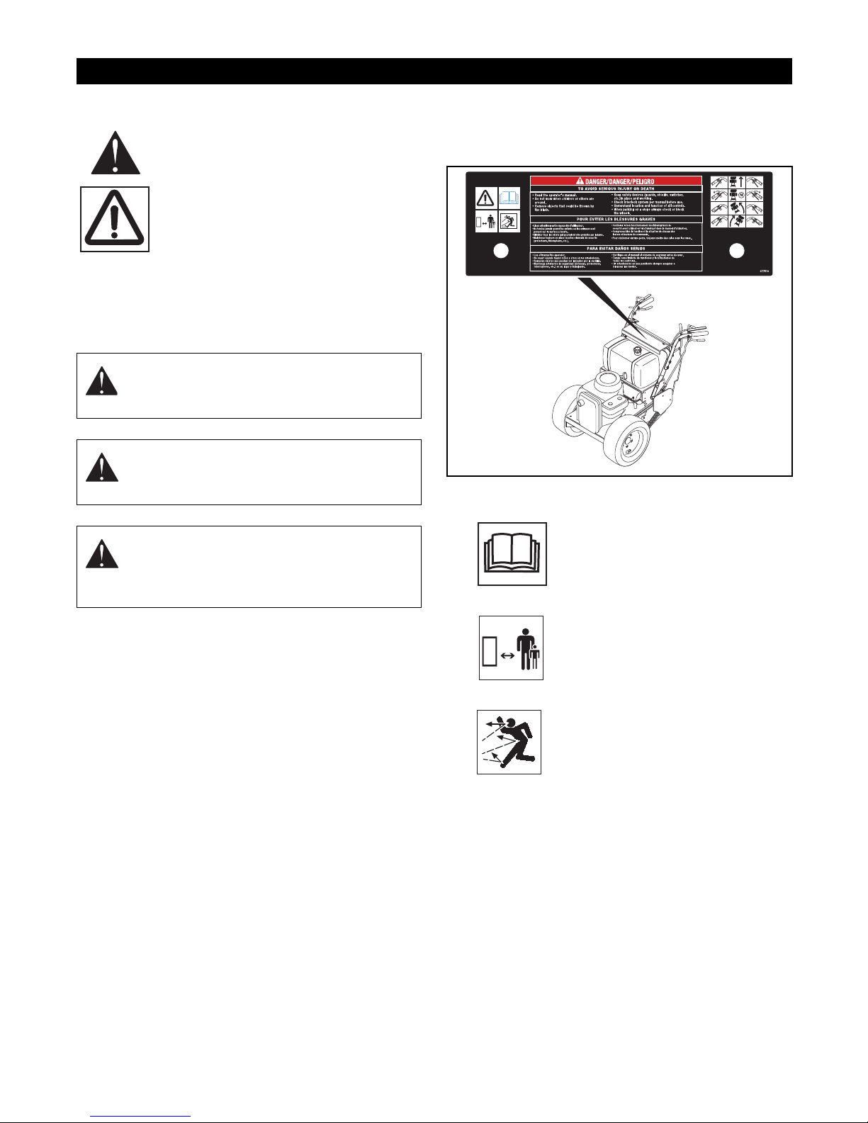
SAFETY DECALS AND LOCATIONS
ALWAYS replace missing or damaged Safety Decals.
Refer to figure below for Safety Decal locations.
1
OG1081
1. DANGER! To avoid serious injury or death
CAUTION: POTENTIALLY HAZARDOUS
SITUATION! If not avoided, MAY RESULT in
minor or moderate injury. It may also be
used to alert against unsafe practices.
NOTATIONS
NOTE: General reference information for proper
operation and maintenance practices.
IMPORTANT: Specific procedures or information
required to prevent damage to unit or attachment.
PRACTICES AND LAWS
Practice usual and customary safe working
precautions, for the benefit of yourself and others.
Understand and follow all safety messages. Be alert to
unsafe conditions and the possibility of minor,
moderate, or serious injury or death. Learn applicable
rules and laws in your area.
REQUIRED OPERATOR TRAINING
Original purchaser of this unit was instructed by the
seller on safe and proper operation. If unit is to be used
by someone other than original purchaser; loaned,
rented or sold, ALWAYS provide this manual and any
needed safety training before operation.
Read the operator’s manual.
OL1801
Keep children and others away from
unit while operating.
Never direct discharge toward other
people. Thrown objects can cause
injury.
OL0910
• Keep all controls, guards and safety
shields properly serviced and functional.
• Check interlock system per manual before
use.
• Understand location and function of all
controls.
• Never allow operation by untrained
persons.
• When parking on a slope always chock or
block the wheels.
GB - 5

OPERATIONAL SAFETY RULES
Walk Around Inspection
Complete a walk around inspection of unit and work
area to understand:
• Work area
• Your unit
• All safety decals
Work Area
ALWAYS check overhead and side clearances carefully
before operation.
ALWAYS be aware of traffic when operating along
streets or curbs.
Keep children and people away.
Keep children out of work area and under watchful care
of a responsible adult.
Keep area of operation clear of all toys, pets, and
debris. Thrown objects can cause injury.
Check for weak spots on dock, ramps or floors. Avoid
uneven work areas and rough terrain.
Avoid slippery surfaces. ALWAYS be sure of your
footing.
DO NOT operate on wet grass.
Dust, smoke, fog, etc. can reduce vision and cause an
accident. Operate unit only when there is good visibility
and light.
Personal Safety
• Only trained adults may operate unit
• Training includes actual operation
NEVER allow children to operate or play on or near
unit.
Be alert and shut off unit if children enter area.
Never carry passengers.
NEVER operate unit after or during the use of
medication, drugs or alcohol. Safe operation requires
your complete and unimpaired attention at all times.
NEVER allow anyone to operate this unit when their
alertness or coordination is impaired.
Wear adequate safety gear, protective gloves and
footwear.
NEVER wear open sandals or canvas shoes during
operation.
Protect eyes, face and head from objects that may be
thrown from unit. Wear appropriate hearing protection.
Sharp edges can cut. Moving parts can cut off fingers
or a hand. Wrap blade(s), wear gloves and use extreme
caution when servicing.
IMPORTANT: On multi-blade mowers, rotation of one
blade will cause all blades to rotate.
ALWAYS keep hands and feet away from all rotating
parts during operation. Rotating parts can cut off body
parts.
ALWAYS keep hands away from all pinch points.
DO NOT touch unit parts which might be hot from
operation. Allow parts to cool before attempting to
maintain, adjust or service.
NEVER place your hands or any part of your body or
clothing inside or near any moving part while unit is
running.
DO NOT wear loose clothing or jewelry. Tie back hair
that may get caught in rotating parts.
Keep children and people away from unit during
operation.
Fumes from engine exhaust can cause injury or death.
DO NOT run engine in an enclosed area. Always
provide good ventilation.
Thrown objects can cause injury and property damage.
DO NOT point discharge at anyone or discharge
directly onto paved or gravel surfaces.
Always stand clear of the discharge area when
operating this unit.
Operation
Understand:
• How to operate all controls
• The functions of all controls
• How to STOP in an Emergency
• Braking and steering characteristics
• Turning radius and clearance
ALWAYS keep protective structures, guards, and
panels in good repair, in place and securely fastened.
NEVER modify or remove safety devices.
ALWAYS keep discharge cover or complete grass
catcher in place and in proper working condition.
Check steering control operation frequently. Adjust and
service as required.
Safety Interlock System must function properly. DO
NOT operate unit if operator presence control is
damaged or disabled.
If equipment vibrates abnormally, stop engine at once,
disengage PTO, wait for all moving parts to stop, and
remove key. Check for any damage or loose parts.
Repair before restart.
Before starting engine: disengage PTO and place unit
in neutral.
DO NOT operate at too fast a rate. DO NOT change
engine governor settings or over-speed engine. Slow
down and turn corners slowly.
Disengage PTO when attachment is not in use.
ALWAYS turn off power to attachment when
transporting, crossing driveways, etc.
GB - 6

•
Avoid uneven and rough terrain. DO NOT operate near
drop offs, ditches, or embankments. Unit can suddenly
turn over if a wheel is over the edge of a cliff or ditch, or
if an edge caves in.
DO NOT try to stabilize unit by putting foot on ground
when operating with applicable riding attachments.
When engine is running and speed control lever is
forward, holding only one steering lever will cause unit
to circle around one drive wheel.
ALWAYS disengage PTO, stop unit and engine,
remove key and allow moving parts to stop before
leaving operator’s position.
Never leave a running unit unattended. ALWAYS shut
off engine before leaving unit.
ALWAYS remove key to prevent unauthorized use.
DO NOT operate in reverse unless absolutely
necessary. ALWAYS backup slowly. ALWAYS look
down and behind, before and while backing.
Hazardous Slopes
DO NOT operate on steep slopes. DO NOT operate on
slopes of more than 10°. Operate across the face of
slopes, not up and down.
Keep all movement on slopes slow and gradual. DO
NOT make sudden changes in speed or direction. Use
a slow speed to avoid stopping or shifting on slopes.
Avoid starting or stopping on a slope.
DO NOT park unit on a slope unless absolutely
necessary. When parking on a slope always chock or
block wheels.
Transport
Use extra care when loading or unloading unit onto
trailer or truck.
Secure unit chassis to transport vehicle. NEVER
secure from rods or linkages that could be damaged.
DO NOT transport machine while engine is running.
Cleaning
Keep unit free of grass, leaves, or other debris. Clean
up oil or fuel spills.
Spark Arrester
This product is equipped with an internal combustion
engine. DO NOT use on or near any unimproved, forest
covered or brush covered land unless the exhaust
system is equipped with a spark arrester meeting
applicable local, state or federal laws. A spark arrester,
if used, must be maintained in effective working order
by the operator.
FUEL SAFETY RULES
Fuel is highly flammable and its vapors are explosive.
Handle with care. Use an approved fuel container.
No smoking, No sparks, No flames. ALWAYS allow
engine to cool before servicing.
NEVER fill fuel tank when engine is running or hot from
operation.
NEVER fill or drain fuel tank indoors.
Replace fuel cap securely and clean up spilled fuel.
BATTERY SAFETY RULES
Battery posts, terminals and related accessories
contain lead and lead compounds, chemicals known to
the State of California to cause cancer and
reproductive harm. Wash hands after handling.
Reverse connections may cause sparks which may
result in injury. ALWAYS connect/disconnect cables in
proper order.
Poisonous battery fluid contains sulfuric acid and its
contact with skin, eyes, or clothing can cause severe
burns.
Explosive Gases! No flames, No sparks, No smoking
near battery.
ALWAYS wear safety glasses and protective gear near
battery.
DO NOT TIP battery beyond a 45° angle in any
direction.
ALWAYS keep batteries out of reach of children.
Battery Electrolyte First Aid
External Contact: Flush with water.
• Eyes: Flush with water for at least 15 minutes
and get medical attention immediately!
• Internal Contact: Drink large quantities of water.
Follow with Milk of Magnesia, beaten egg or
vegetable oil. Get medical attention immediately!
DO NOT induce vomiting!
MAINTENANCE AND SERVICE SAFETY
RULES
Before making any inspections, repairs, etc.:
disengage PTO, stop unit and engine, remove key,
allow moving parts to stop.
Allow hot parts to cool.
ALWAYS block wheels and know all jack stands are
strong, secure and will hold weight of unit during
maintenance.
ALWAYS maintain unit in safe operating condition.
Damaged or worn out muffler can cause fire or
explosion.
Keep hardware, especially blade attachment bolts,
tight.
STORAGE SAFETY RULES
For unit storage or extended storage:
• NEVER store with fuel in fuel tank, inside a
building where any ignition sources are present.
• Allow engine to cool completely.
GB - 7

ACCESSORY AND ATTACHMENT SAFETY
RULES
Use only attachments or accessories designed for your
unit.
Check attachment components frequently. If worn or
damaged, replace with manufacturer’s recommended
parts.
ASSEMBLY
WARNING: AVOID INJURY. Read and
understand Assembly, Fuel and Battery
Safety Rules before proceeding.
1. Remove the power unit from shipping container.
2. Adjust tire pressure to 12 to 15 psi (83 to 103
kPa).
3. For electric start models, charge and connect
battery. See Service & Adjustments.
OPERATION
Use extra care with grass catchers and other
attachments. These can change the stability of the unit.
Use only approved hitch points.
ALWAYS be aware of attachments when turning.
ALWAYS allow adequate clearance between
attachments, personnel, and other objects.
4. Check the adjustments outlined in Service &
Adjustments .
5. Add clean fuel to the fuel tank. See engine
manual for type and grade.
6. Mount mower to unit.
7. Check for loose hardware.
8. Be sure that safety interlock system operates
correctly. See Maintenance .
9. Be sure that unit tracks straight. See
Adjustments .
WARNING: AVOID INJURY. Read and
understand Operational, Fuel and Battery
Safety Rules before proceeding.
CONTROLS AND FEATURES
Safety Interlock System
The engine will only start with the PTO disengaged and
the shift lever in neutral.
DANGER: SAFETY INTERLOCK SYSTEM
FAILURE and improper operation of unit can
result in death or serious injury. ALWAYS
know the safety interlock system is operating
properly. See Maintenance for testing
instructions.
Operator Presence Control
When the shift lever or PTO is engaged, the operator
presence control stops the engine when the operator
presence control lever is released. The operator
presence control lever must be depressed to operate
the PTO or traction drive.
Steering Levers
The steering levers are used to steer, operate in
forward and reverse, and stop the unit. When held in
neutral, the brakes are engaged.
Steering Lever Latches
The red steering lever latches hold the steering levers
in the neutral lock position.
1
1
Ignition Switch (Electric Start
2
Models)
3
Operate the ignition switch with the
removable key. The switch has three
positions: Off (1), On (2) and Start (3). To
OF1210
start the engine, turn the key to Start, then
release to Run. To stop the engine, turn
the key to Off.
Ignition Switch (Recoil Start
Models)
Operate the ignition switch with the
2
removable key. The switch has two
positions: Off (1) and On (2). To start the
OF1211
engine, turn the key to On and pull the
recoil handle. To stop the engine, turn the
key to Off.
CAUTION: AVOID INJURY. Operate only
when presence control is functioning
correctly.
GB - 8

Throttle/Choke Lever (Recoil Start
1
Models)
The Throttle/Choke lever changes the speed
2
of the engine and chokes the engine for cold
starts. Place the lever in Choke (1) to start a
cold engine. Move the lever to Fast (2) to
increase engine speed. Move the lever to
3
Slow (3) to decrease engine speed.
OG1061
Throttle Lever (Electric Start Models)
1
The throttle lever changes the speed of the
engine. Move the throttle lever to Fast (1) to
increase engine speed. Move the lever to
Slow (2) to decrease engine speed.
2
OG1180
Choke Control (Electric Start
Models)
Use the choke control to start a cold
engine. Pull the control out to choke the
OG1190
engine. Push the control in when the
engine gets warm.
3. Release both steering levers slowly.
PTO Clutch
Push the PTO (power take off) lever On
1
(1) to engage the mower. Pull the PTO
lever Off (2) to disengage the mower.
2
OE0260
Recoil Starter Handle
Pull the recoil starter handle to start the engine.
Hour Meter (Electric Start Models)
0 0 0 0
0
0
HOURS
1/10
The hour meter measures the number of
hours that the key is in the run position.
OG0620
Oil Pressure Light (Electric Start
Models)
OG0600
The red light near this symbol comes on
when the key is turned to run and the engine oil
pressure is low. Check oil level and add if necessary.
See Engine Manual.
Shift Lever
The shift lever sets the direction and speed of the unit.
“R” is for reverse, “N” for neutral, “1” indicates the
slowest forward speed. The numbers from “2” to “5”
indicate increasingly faster forward speeds.
R
N
1
2
3
4
5
OG1040
To shift unit:
1. Stop unit movement by pulling both steering
levers all the way up.
2. You can move the shift lever one of two ways:
• Continue to hold up both steering levers and use
your knee to move the shift lever to the desired
position.
• Lock both steering lever latches. Move the shift
lever to the desired position. Hold the steering
levers up as you unlock the latches.
FILL FUEL TANK
WARNING: Use caution with fuel. Fuel is very
flammable.
Keep fuel in a clean and tight container.
Keep fuel away from fire or heat. Never put
fuel in the fuel tank while the engine is
running or hot.
Clean up any spilled fuel before starting the
engine.
Add fuel to the fuel tank as needed. See engine
manual for type and grade of fuel.
To add fuel to the fuel tank:
1. Put the unit in an open area.
2. Stop the engine.
3. Allow engine to cool.
4. Clean the fuel cap and the area around the fuel
cap to prevent dirt from entering the fuel tank.
5. Remove the cap from the fuel tank.
6. Fill the fuel tank. Be careful not to spill.
7. Install the cap on the fuel tank and tighten.
8. Clean up any spilled fuel before starting the
engine.
WARNING: When engine is running and
transmission is in gear, engaging one
steering lever latch and releasing the
opposite steering lever causes unit to circle
around one drive wheel.
TO STOP IN AN EMERGENCY
1. Turn the ignition key Off.
2. Allow engine to stop completely.
3. Engage steering latches in neutral lock.
GB - 9

TO START AND SHUT OFF ENGINE
Before Each Use
Check each item in Before Each Use in the
Maintenance Schedule.
NOTE: The engine will not start unless the shift lever is
in neutral and the Power Take Off (PTO) is Off.
Starting with Recoil Handle
1. Lock the steering lever latches in neutral.
2. Put the shift lever in neutral.
3. Move PTO switch to Off.
4. Set throttle to the proper starting position. If the
engine is cold, choke the engine.
5. Turn ignition switch to On.
6. Grasp recoil starter handle and pull rope out
slowly until it pulls harder. This is the compression
stroke.
7. Let the rope rewind slowly.
8. Pull rope with rapid continuous full arm stroke to
start engine. Allow rope to rewind slowly.
IMPORTANT: DO NOT let starter handle snap against
engine.
9. Repeat until engine starts. (If engine does not
start, refer to Engine Manual.)
10. After engine starts, adjust choke as needed.
Allow engine to warm and run smoothly before
operating unit.
Starting with Electric Start
To start the engine:
1. Lock the steering lever latches in neutral.
2. Put the shift lever in neutral.
3. Move PTO switch to Off.
4. If the engine is cold, choke the engine.
5. Move the throttle to Fast.
6. Put the ignition key in the switch and turn it to
Start.
7. When the engine starts, release the key to Run
position.
IMPORTANT: DO NOT operate starter motor more
than 15 seconds per minute, as overheating and
damage can occur. If engine will not start, refer to
Troubleshooting or Engine Manual.
8. Release the choke. Allow engine to warm and run
smoothly before operating unit.
TO OPERATE UNIT
Operate the unit only when in the operator’s position
directly behind the handlebars.
WARNING: When the engine is running and
the speed control lever is engaged, holding
only one steering lever in neutral causes the
unit to circle sharply around one drive wheel.
To operate:
1. Lock the steering latch levers in neutral.
2. Place PTO in Off position.
3. Place shift lever in Neutral.
4. Start the engine. Allow the engine to warm and
run smoothly.
5. Move the throttle lever to the Fast position.
6. Engage the operator presence control and move
shift lever to desired direction and speed.
7. Hold steering levers in neutral and release
steering latch levers.
WARNING: When the engine is running and
the shift lever is engaged, releasing only one
steering latch causes the unit to circle
around one drive wheel.
ALWAYS hold both steering levers in the
neutral position when releasing the steering
lever latches.
ALWAYS release levers slowly.
• To move straight forward; slowly release both
steering levers to the full outward position.
OG1140
• To stop or place unit in neutral lock, pull both
levers all the way up and engage both steering
latches.
OG1150
Shut Off
1. Engage steering latches in neutral lock.
2. Move the throttle lever to Slow.
3. Turn the ignition key Off.
4. Allow engine to stop completely.
• To turn to the left; pull the left hand lever up.
OG1200
GB - 10

• To turn to the right; pull the right hand lever up.
3. Pull both levers all the way up and engage both
steering latches. The brake is applied when the
steering levers are in neutral.
4. Chock or block the wheels if parked on a slope.
OG1210
• To move in reverse:
1. Place steering levers in neutral.
2. Engage steering lever latches.
3. Engage the operator presence control and move
shift lever to Reverse.
4. Hold steering levers in neutral and release
latches.
5. Release steering levers slowly.
WARNING: Uncontrolled reverse travel can
result in serious injury.
Do not put shift lever into the reverse position
unless you are prepared to operate in
reverse.
To mow:
1. Place steering levers in neutral.
1. Engage steering lever latches.
1. Move the shift lever to the neutral position.
2. Slow the engine down to about half speed.
3. Engage operator presence control lever.
4. Move the PTO switch to On to engage mower.
5. Move the throttle lever to the Fast position.
IMPORTANT: NEVER engage the PTO if the mower is
plugged with grass or other material. This will damage
the PTO belt.
6. Move the shift lever to set a slow ground speed.
7. Hold steering levers in neutral and release
latches.
8. Release steering levers slowly.
When you know how to operate the unit, select a speed
appropriate to your mowing conditions.
To disengage mower, move the PTO switch to Off.
To stop:
1. Pull both steering levers to neutral position.
2. Lock the steering lever latches in neutral.
3. Keep one hand on the operator presence control
and move the shift lever to the neutral position.
4. Move the throttle lever to Slow.
5. Turn the ignition key to Off.
TO PUSH UNIT BY HAND
To move the unit without the engine running:
1. Turn the engine off.
2. Move shift lever to neutral.
3. Hold steering levers in neutral and disengage
latches. Release steering levers. The brake is
disengaged when the steering levers are
released.
IMPORTANT: Never tow unit.
TO TRANSPORT UNIT
ALWAYS shut off engine, remove key and drain fuel
when transporting unit on a truck or trailer. Use extra
care when loading or unloading unit onto trailer or
truck.
Secure unit chassis to transport vehicle. NEVER
secure from rods or linkages that could be damaged.
DO NOT transport machine while engine is running.
PARKING
1. Stop unit and shut off engine.
2. Remove the key.
GB - 11

WARNING: AVOID INJURY. Read and
understand Maintenance and Service and
Battery Safety Rules before proceeding.
MAINTENANCE SCHEDULE
Each
Use
Check Safety Interlock
System
Check Air Cleaner
25 50 100
•
•
MAINTENANCE
The engine MUST stop whenever the operator
removes both hands from controls while the PTO or
transmission is engaged. To test:
1. Start engine and engage PTO.
2. Release operator presence control lever. Engine
must stop.
3. Disengage PTO.
4. Restart engine.
5. Place shift lever in first Forward speed.
6. Release operator presence control lever. Engine
must stop.
Check Engine Oil
Check Engine Cooling
Check Fasteners
Check Tire Pressure
Check Battery and Battery
Fluid
Check All Belts
General Lubrication
Change Engine Oil
Check Fuel Filter
Check Spark Plug
Check Muffler
•
•
•
•
•
•
•
•
•
•
•
CHECK SAFETY INTERLOCK SYSTEM
Test the safety interlock system at each operation. If
the system does not function properly, do not operate
the unit until repairs are made.
Engine must not start unless PTO is disengaged and
the speed control lever is in neutral. To test:
1. With engine off, engage PTO.
2. Turn electric start model ignition switch to Start.
Engine must not crank. Turn recoil start model
ignition switch to Run. Pull recoil start handle.
Engine must not start.
3. Place speed control lever in Forward.
4. Turn electric start model ignition switch to Start.
Engine must not crank. Turn recoil start model
ignition switch to Run. Pull recoil start handle.
Engine must not start.
CHECK AIR CLEANER
Check the air cleaner element daily. See engine
manual for detailed instructions.
CHECK ENGINE OIL
Check the engine oil level daily. Never operate the
engine when the oil level is low. See engine manual for
detailed instructions.
CHECK ENGINE COOLING
Check the engine air cooling system daily. See engine
manual for detailed instructions.
CHECK FASTENERS
Check all nuts, bolts, and other fasteners daily. Replace
fasteners that are missing or damaged.
CHECK TIRE PRESSURE
Check tires for proper inflation, excessive wear or
damage daily. The correct air pressure is 12 to 15 psi
2
(83 to 103 kN/m
).
CHECK BATTERY (ELECTRIC START
MODELS)
WARNING: AVOID INJURY. Read and
understand Battery Safety Rules before
attempting any maintenance.
Terminals
Inspect battery and terminals monthly.
To clean terminals:
1. Remove battery from unit by removing cables.
2. Remove tie down rod nuts and lift battery out.
3. Clean or service battery away from unit. Remove
corrosion from battery terminals and cable
connections with wire brush, then wash with a
weak baking soda solution.
GB - 12

4. Apply a thin coat of grease or petroleum jelly to
terminals and cable ends to retard corrosion.
5. Reinstall battery.
Electrolyte Level
Check electrolyte level every 25 hours of operation.
Check each cell:
1. Remove caps one at a time. The electrolyte level
should be at level indicated.
2. Fill each cell with distilled water if needed.
3. Reinstall and tighten each cap.
IMPORTANT: When adding distilled water to battery
during freezing weather, battery must be charged to
mix water with existing electrolyte.
1
2
2
1
1. Wheel Bearings
2. Caster Pivots
3. Half-Shafts
1
3
1
OG1250
CHECK ALL BELTS
Check all belts for wear or damage every 50 hours.
See Adjustments to set proper belt tension.
GENERAL LUBRICATION
Apply a small amount of oil to the pivot points as
required for smooth operation.
Apply high quality lithium based grease to all lube
fittings every 50 hours of operation.
SERVICE AND ADJUSTMENTS
WARNING: AVOID INJURY. Read and
understand Maintenance and Service and
Battery Safety Rules before proceeding.
STEERING LEVER ADJUSTMENT
1. Turn off the engine, remove the key and allow unit
to cool.
2. Disengage neutral lock and release lever.
3. Shift transmission into neutral. Operate steering
levers several times. Do not move unit.
4. Remove hair pin and clevis pin from the clevis on
the steering control rod.
5. Adjust the clevis on the steering control rod until
the gap between the ends of the steering lever
and handlebar grip is 2-1/2 to 3 inches.
6. Reinstall the clevis pin and hair pin.
7. Repeat for other steering lever.
CHANGE ENGINE OIL
See engine manual for detailed instructions.
CHECK FUEL FILTER
See engine manual for detailed instructions.
CHECK SPARK PLUG
See engine manual for detailed instructions.
CHECK MUFFLER
Check muffler for damage or wear. Replace if
necessary.
2
1
2-1/2"
to
3"
1. Handlebar Grip
2. Steering Lever
3. Steering Control
Rod
4. Wheel Clutch Arm
Weldment
5. Steering Control
Rod Clevis
6. Clevis Pin and
Hairpin
3
5
6
4
OG0751
GB - 13

ADJUSTING THE BRAKES
NOTE: The traction belt must disengage as the brake
starts to engage.
1. Turn off the engine, remove the key and allow unit
to cool.
2. If brakes do not disengage fully when traction belt
is engaged, the brakes are too tight. Loosen the
locknut.
3. If brakes do not engage fully when traction belt is
disengaged, the brakes are too loose. Tighten the
locknut.
4. Start engine and test in low gear for proper brake
engagement.
Brake Rod
Lock Nut
2. Release the steering levers.
3. Raise the rear of the unit so that the drive wheels
are off the ground.
4. Remove traction belt guard.
5. Remove clutch idler pulley spring.
WARNING: AVOID INJURY. An extension
spring, when extended, stores energy and
can be dangerous. Always use tools
specifically designed for installing or
removing an extension spring. Always
compress or extend springs slowly.
6. Remove hair pin and clevis pin holding steering
control rod to wheel clutch arm weldment.
1
Brake Band
ADJUSTING PTO CLUTCH
1. Turn off engine, remove key and allow hot parts to
cool.
2. Move the PTO lever to On.
3. Loosen the two jam nuts on the rear end of the
PTO actuating rod.
4. Turn the two jam nuts forward until the gap in the
coils of the spring is approximately .030" (.76
mm).
2
3
1. PTO Actuating Rod
2. Jam Nuts
1
3. Spring
5. Lock the two jam nuts on the PTO actuating rod.
REPLACING THE TRACTION BELTS
1. Turn off the engine, remove the key and allow unit
to cool.
OG0790
2
6
1. Handlebar
2. Steering Lever
3. Steering Control Rod
4. Wheel Clutch Arm
Weldment
5. Brake Rod
8
9
6. Transmission Shaft
Pulley
7. Clutch Idler Pulley
Spring
8. Traction Belt
9. Drive Wheel
3
7
7. While slowly turning the drive wheel, work the
traction belts off the transmission shaft pulley and
drive wheel.
8. Install new traction belts.
IMPORTANT: Always replace belts in sets.
9. Connect steering control rod to wheel clutch arm
weldment with clevis pin and hair pin.
10. Reinstall clutch idler pulley spring.
11. Reinstall traction belt cover.
12. Lower the unit.
13. Check adjustment of steering levers. See
Steering Lever Adjustment.
4
5
OG0751
GB - 14

REPLACING THE TRANSMISSION BELT
1. Stop the engine. Remove ignition key. Put PTO
lever in the ”OFF” position. Put the shift lever in
neutral.
2. Loosen belt finger plate and remove mower belt
from engine sheave.
1
2
3
4
1. Fixed Idler Pulley
2. Transmission
Sheave
3. Engine Sheave
4. Transmission Belt
5. Belt Finger Plate
5
OG0790
To adjust:
1. Stop the engine. Remove ignition key. Put PTO
lever in the ”OFF” position. Put the shift lever in
neutral.
2. Loosen two 5/16-18 bolts in shift lever.
3. Center shift lever vertically in Forward slot, just
touching the reverse stop.
Reverse Stop
Center in Slot
OG1240
Shift Lever
4. Tighten bolts securely.
NOTE: You should not be able to shift into reverse
without pushing down on the shift lever.
3. Loosen the 3/8-16 bolt which fastens the fixed
idler pulley to the frame. Slide the pulley to end of
slot. Remove the bolt, spacer and idler pulley if
necessary.
4. Remove old transmission drive belt.
5. Install new transmission belt in the top groove of
the clutch hub and on the transmission sheave.
6. Tension the belt with fixed idler pulley and tighten
the 3/8-16 nut and bolt.
NOTE: It may be necessary to re-tension this belt
during break-in.
7. Reinstall mower belt on engine sheave. Tighten
the belt finger plate.
ADJUSTING SHIFT LEVER LINKAGE
The transmission shift lever is attached to the
transmission shift arm with two 5/16-18 bolts.
2
3
ADJUSTING THE UNIT TO TRACK
STRAIGHT
NOTE: When adjusting tire pressure, do not exceed 15
psi (103 Kn/m
3
) maximum inflation pressure.
If unit turns to the right, try each of the following
steps until the unit tracks straight. If may not be
necessary to perform all the steps.
1. Reduce the air pressure in the left tire.
2. Increase the air pressure in the right tire.
If unit turns to the left, try each of the following steps
until the unit tracks straight. It may not be necessary to
perform all the steps.
1. Reduce the air pressure in the right tire.
2. Increase the air pressure in the left tire.
BATTERY (ELECTRIC START MODELS)
WARNING: AVOID INJURY. Read and
understand Battery Safety Rules before
attempting any maintenance.
Charge Battery
1
1. Transmission
2. Shift Lever
3. 5/16-18 Bolts
4. Adjustment Slots
WARNING: FROZEN BATTERIES CAN
4
EXPLODE and result in death or serious
injury.
DO NOT charge a frozen battery. Let the
battery thaw before charging.
IMPORTANT: DO NOT fast charge. Charging at a
higher rate will damage or destroy battery.
OG1230
ALWAYS follow information provided on battery by
battery manufacturer. Contact battery manufacturer for
detailed instructions.
GB - 15

1. Put unit into service position.
2. Disconnect negative (–) cable first, then positive
(+) cable.
3. Remove hold down and remove battery.
4. Place battery on bench or other well-ventilated
place where electrolyte spill will not create
damage.
5. Initial Battery Setup - Remove caps and fill each
cell to level indicated with electrolyte at 1.230±
specific gravity and 80°F (27°C).
• Let battery stand for thirty minutes.
• Check electrolyte level and add more if
necessary.
6. Connect positive (+) lead of charger to positive
(+) terminal, and negative (–) lead to negative (–)
terminal.
7. Charge the battery at two and a half amps for ten
hours or until all cells are gassing freely and the
specific gravity is constant over three 30 minute
intervals.
8. Immediately after charging, check electrolyte
level. If low, add distilled water to bring cell up to
required level.
9. Replace caps finger tight.
10. Wash off and dry battery.
11. Reinstall battery into unit and connect positive (+)
cable first, then negative (–) cable.
3. Connect the other end of the same jumper cable
to the positive (+) terminal of the booster battery.
4. Connect one end of the second jumper cable to
the negative (–) terminal of the booster battery.
5. Make the final jumper cable connection to the
engine block or the furthest ground point away
from the discharged battery.
WARNING: Make sure cables are clear of
any moving engine parts before starting
engine.
6. Start engine (refer to Operation Section). If
engine will not start after several tries, unit or
battery may need service.
7. After engine starts, leave cables connected for
one to two minutes.
8. Disconnect cables in reverse order.
9. Operate unit normally to charge battery.
3
2
1. Positive terminal
2. Negative terminal
3. Battery
1
OF1670
Jump Start
It may be possible to recharge the battery by jump
starting the unit and allowing the engine to run. The
unit used for jump starting should have a 12 volt battery
with at least 500 cold cranking amperes, and a
negatively grounded system.
1. Ensure battery is not frozen. If the fluid is frozen,
remove battery from unit and allow it to thaw
before charging.
2. Connect the positive (+) jumper cable to the
positive terminal of the discharged battery.
GB - 16

STORAGE
IMPORTANT: Never spray unit with water or store unit
WARNING: AVOID INJURY. Read and
understand Maintenance and Service and
Storage Safety Rules before proceeding.
outdoors. Store unit in a cool, dry, protected location.
NOTE: Do not use harsh or abrasive cleaners on any
painted surface. Do not allow gasoline or oil to remain
on any decals.
Storage – Two Months or More
Check each item in the Before Each Use, 25 and 50
hour maintenance schedule, but do not add gasoline.
Clean the tractor. Touch up all scratched painted
surfaces.
Engine
Refer to the engine manual to prepare the engine for
storage.
Battery
Remove battery and store in a cool, dry place.
TROUBLESHOOTING
PROBLEM PROBABLE CAUSE CORRECTION
Engine will not
start
Unit will not
move or mow
when the engine
is running
Changes in the
sound or
vibrations of the
unit
Unit will not
move when
operated on an
incline.
1. Safety Interlock System is
preventing start.
2. Fuel tank is empty or fuel is
contaminated.
3. Air cleaner is clogged or
damaged.
4. Safety Interlock System out of
adjustment or defective.
5. Dirty or damaged spark plug.
1. Transmission belt or mower
belt is broken, worn, or off the
pulleys.
1. Loose or missing fasteners.
2. Mower blade problem.
1. Binding in the steering or brake
linkage.
2. Steering levers out of
adjustment.
3. Worn or damaged traction
belts.
4. Transmission shaft pulley
worn.
1. The engine will not start unless the speed
control lever is in the neutral position and the
PTO switch is in the Off position.
2. Add fuel. If necessary, replace the fuel with
clean, fresh fuel.
3. Clean or replace the filter element. See engine
manual.
4. See your Dealer for repairs.
5. See Engine Manual.
1. Check belts for wear, damage and correct
position on pulleys. Replace belts if worn or
damaged. See Service and Adjustments.
1. Check all the fasteners. Replace if necessary.
2. Refer to mower Owner/Operator Manual.
1. Check linkage for debris or damage. Repair if
necessary. See Service and Adjustments or
your Dealer for repairs.
2. See Service and Adjustments.
3. Check belts for wear or damage. Replace if
necessary. See Service and Adjustments.
4. If pulley shows excessive wear, replace it. See
your Dealer for repairs.
GB - 17

ACCESSORIES
See your authorized Gravely dealer to add these
optional accessories.
78800200 Grass Catcher Adapter Kit (36” mower)
78800400 Grass Catcher Adapter Kit (50” mower)
78506700 High Lift Blade Kit (50")
78802900 Mulching Kit (36” mower)
78800800 Mulching Kit (50” mower)
ATTACHMENTS
See your authorized Gravely dealer to add these
attachments to your unit.
888301 36” Side Discharge *
888047 36” Mower
888010 Grass Catcher (Multi-Use)
888048 50” Mower
* CE Certified
SERVICE PARTS
Be sure to always use genuine Gravely parts to keep
your unit running like new.
Part no. Qty Description
78801800 1 Battery
21391300 1 Paper Element - Kawasaki - 14 hp
21391200 1 Foam Precleaner - Kawasaki 14
hp
042926 1 Paper Element - Kawasaki 12.5
hp
042925 1 Foam Precleaner - Kawasaki 12.5
hp
21530000 1 Air Filter - Briggs & Stratton
040742 1 Fuel Filter - Kawasaki
21530400 1 Fuel Filter - Briggs & Stratton
21380000 1 Oil Filter - Kawasaki 14 hp
048832 1 Oil Filter - Kawasaki 12.5 hp
21530700 1 Oil Filter - Briggs & Stratton
21384700 1 Spark Plug - Kawasaki 14 hp
042914 1 Spark Plug - Kawasaki 12.5 hp
21531100 2 Spark Plug - Briggs & Stratton
GB - 18

SPECIFICATIONS
Model Number 988088 988091 988092 988309
Description PRO 150
Length – in (cm) 38.3 (97.3)
Height – in (cm) 39.0 (99.1)
Width – in (cm) 32.8 (83.3)
Actual Weight – lbs (kg) 232 (105.5) 240 (109.1) 232 (105.5)
Battery N/A 12V 13A N/A
Brakes 6" Band
Turning Radius – in (cm) 0
Tire Size 13x6.50-6, 4 Ply Rating
Engine – Manufacturer Kawasaki Briggs & Stratton Kawasaki
FC420V-ES15
Cycle 4
Horsepower – HP(KW) 14 HP 12.5 HP 16 10.9 HP
(8.1 KW @ 2900 min
Starting System Recoil Electric Recoil
Fuel Tank Capacity 4.5 gal U.S. (17.1 L)
-1
)
Fuel See Engine Manual
Governed R.P.M. (max.) 3300 2950
Crank Case Cap. See Engine Manual
Air Cleaner Paper Element, Foam Precleaner
Transmission Peerless 5 Speed + Reverse
Speed– Forward Max. 0 – 5.2 MPH (0 – 8.4 km/hr)
– Reverse Max. 0 – 3 MPH (0 – 4.9 km/hr)
Tire Pressure 12 – 15 PSI (83 - 103 kPa)
Mower 888301
Weight – lbs (kg) 186 (84.4)
Length – in (cm) 42.75 (108.6)
Height – in (cm) 13.5 (34.3)
Width – in (cm) 44.4 (112.8)
Width of Cut – in (cm) 36 (91.4)
Max. Rotation Speed of Cutting Edge
Oper. Ear Sound Pressure (Lpa) dB
Sound Power (L
VIBRATION MEASURE (m/s
@ Operator hands X axis <3.0
wa
) dB
A
A
2
)
Y axis 3.4
Z axis <2.5
3505 min
-1
86
100
GB - 19

2 Year Limited Warranty
Ariens Company hereby warrants to the original consumer purchaser
Gravely Division of Ariens Company
655 West Ryan Street
P.O. Box 157
Brillion, WI 54110-0157
920-756-2141
Fax 920-756-2407
This warranty is subject to the following exceptions, conditions, and limitations:
Usage Requirement
The duration of this warranty shall be ninety days or 1000 hours, whichever comes first, if the product is rented or leased.
that all Gravely Two-Wheel, Professional G, Pro, and ProMaster products
will be free from defects in material and workmanship for a period of
two (2) years from the date of purchase or 1000 hours, whichever
comes first.
Protection Plan
Ariens Company will repair or replace any part found upon examination
by the Ariens Company to be defective. Such repair or replacement
will be free of charge to the purchaser (labor and parts), except as
noted below.
Purchaser’s Responsibilities
• The purchaser must perform maintenance & minor adjustments
per the operator’s manual.
• The purchaser must notify Ariens Company or an authorized
Gravely service representative of the need for warranty service.
• The purchaser must transport the product to and from the place
of warranty repair.
Product Registration
• The Gravely dealer must fill out and return the warranty
registration card to validate the warranty.
Service Parts and Accessories
• Service parts and accessories not purchased with the product
covered by this warranty are warranted to be free of defects
for a period of ninety (90) days following the date of purchase,
and will be replaced free of charge (except for labor).
Service
• Warranty service must be done by an authorized Gravely dealer.
To find a Gravely dealer near you, contact Ariens Company.
Battery Warranty Prorated
• One to three months - Free replacement
• Four to twelve months - Prorated over 12 months
Ariens Company may from time to time change the design of its products. Nothing contained in this warranty shall be construed as
obligating Ariens Company to incorporate such design changes into previously manufactured products, nor shall such changes be
construed as an admission that previous designs were defective.
Exclusions (No Warranty)
• Normal maintenance, services, and normal replacement items,
such as spark plugs, oil, oil filters, air filters, mufflers, belts,
tires, shoes, runners, scraper blades, shear bolts, mower blades,
mower vanes, headlights, light bulbs, knives, etc. are not covered
by this warranty.
• Any equipment which has been altered, misused, misassembled,
improperly adjusted, neglected, or damaged by accident is not
covered by this warranty.
• Service completed by someone other than an authorized
Gravely dealer is not covered by this warranty.
• Any attachment not approved by Gravely nor any parts that
are not genuine Gravely service parts are not covered by this
warranty.
• Engines and engine accessories are covered only by the
warranty made by the engine manufacturer, and are not covered
by this warranty.
• This warranty applies only to products purchased in the United
States (including Puerto Rico) and Canada. In all other countries,
contact place of purchase.
LIMITATION OF REMEDY AND DAMAGES
Ariens Company’s liability under this express warranty, and under
any implied warranty that may exist, is limited to repair or replacement
of any defective part. In no event shall Ariens Company be liable
for incidental, special, or consequential damages (including lost
profits). This warranty gives you specific legal rights. You may also
have other rights which vary from state to state. Some states do
not allow the exclusion of incidental or consequential damages, or
limitations on how long an implied warranty lasts, so the above
limitations and exclusions may not apply to you.
DISCLAIMER OF FURTHER WARRANTY
Ariens Company makes no warranty other than
what is expressly made in this warranty. If the law
of your state provides that an implied warranty of
merchantability, or an implied warranty of fitness
for a particular purpose, applies to Ariens Company,
any such implied warranty is limited to the duration
of this express warranty.
Form: GLW2-062399
GB - 20

GRAVELY
A Division of Ariens Company
655 West Ryan Street
P.O. Box 157
Brillion, WI 54110-0157
920-756-2141
Fax 920-756-2407
www.gravely.com
 Loading...