

Gravely 990018, 990020 Owner's Manual
USER’S MANUAL
Smoke Alarms
AC Powered Ionization Smoke
Alarm with Silence and
Latching Features
Model 9120
Input: 120V AC ~, 60 Hz, 0.04A
AC Powered Ionization Smoke
Alarm with Battery Back-up,
Silence and Latching Features
Model 9120B
Input: 120V AC ~, 60 Hz, 0.04A
Printed in Mexico
M08-0134-003 K1 04/07
IMPORTANT! PLEASE READ CAREFULLY AND SAVE
This user’s manual contains important information about your Smoke Alarm’
operation. If you are installing the Smoke Alarm for use by others, you must
leave this manual — or a copy of it — with the end user.
TABLE OF CONTENTS
Introduction . . . . . . . . . . . . . . . . . . . . . . . . . . . . . . . . . . . . . . . . . . . . . . . . .1
Fire Safety Tips . . . . . . . . . . . . . . . . . . . . . . . . . . . . . . . . . . . . . . . . . . . . . .1
Before You Install This Smoke Alarm . . . . . . . . . . . . . . . . . . . . . . . . . .1-2
How To Install This Smoke Alarm . . . . . . . . . . . . . . . . . . . . . . . . . . . . .2-3
Optional Locking Features . . . . . . . . . . . . . . . . . . . . . . . . . . . . . . . . . . . . .4
Understanding the Indicator Lights
and Alarm Horn Patterns . . . . . . . . . . . . . . . . . . . . . . . . . . . . . . . . . . . . . .5
Weekly Testing . . . . . . . . . . . . . . . . . . . . . . . . . . . . . . . . . . . . . . . . . . . . . . .5
Regular Maintenance . . . . . . . . . . . . . . . . . . . . . . . . . . . . . . . . . . . . . . . . .5
If This Smoke Alarm Sounds . . . . . . . . . . . . . . . . . . . . . . . . . . . . . . . . . . .5
What To Do In Case Of Fire . . . . . . . . . . . . . . . . . . . . . . . . . . . . . . . . . . . .5
Using the Silence Feature . . . . . . . . . . . . . . . . . . . . . . . . . . . . . . . . . . . . .5
“Latching Alarm” Indicator . . . . . . . . . . . . . . . . . . . . . . . . . . . . . . . . . . . .6
If You Suspect a Problem . . . . . . . . . . . . . . . . . . . . . . . . . . . . . . . . . . . . . .6
Recommended Locations For Smoke Alarms . . . . . . . . . . . . . . . . . . . . .6
Locations To Avoid For Smoke Alarms . . . . . . . . . . . . . . . . . . . . . . . . .6-7
About Smoke Alarms . . . . . . . . . . . . . . . . . . . . . . . . . . . . . . . . . . . . . . . . .7
Special Compliance Considerations . . . . . . . . . . . . . . . . . . . . . . . . . . . . .7
Limitations of Smoke Alarms . . . . . . . . . . . . . . . . . . . . . . . . . . . . . . . . . . .7
Limited Warranty . . . . . . . . . . . . . . . . . . . . . . . . . . . . . . . . . . . . . . . . . . . . .7
© 2007 BRK Brands, Inc., a subsidiary of Jarden Corporation.
3901 Liberty Street Road, Aur
All rights reserved.
Consumer Affairs: (800) 323-9005
www.brkelectronics.com • www.firstalert.com
ora, IL 60504-8122
INTRODUCTION
Thank you for choosing BRK Brands, Inc. for your Smoke Alarm needs.
You have purchased a state-of-the-art Smoke Alarm designed to provide
you with early warning of a fire.
Key features include:
Smart Technology designed to help reduce unwanted or nuisance alarms.
Single Button Test/Silence eliminates confusion. Depending on what
mode the alarm is in, pushing the button provides dif
as testing the alarm, silencing the alarm, re-testing the alarm when in
silence and clearing the Latching feature.
Latching Alarm Indicator easily identifies initiating alarm even after the
alarm condition has subsided.
Perfect Mount System includes a gasketless base for easy installation and
new mounting bracket that keeps the alarm secure over a wide rotation
a
range to allow for perfect alignment.
Dust Cover is included to keep the alarm clean during construction.
Easy Installation/Maintenance features include a large opening in the
ounting bracket for easy access to wiring. A battery pull tab keeps the
m
battery fresh until the home is occupied. A Side Load Battery Drawer allows
for easy battery replacement without removing the alarm from the ceiling or
wall (Model 9120B only).
Improved UV Resistance keeps the alarm from discoloring over time.
ferent functions such
Models 9120
9120B
s
All First Alert®and BRK®Smoke Alarms conform to regulatory
requirements, including UL217 and are designed to detect particles of
combustion. Smoke particles of varying number and size are produced
in all fires.
Ionization technology is generally more sensitive than photoelectric
technology at detecting small particles, which tend to be produced
in greater amounts by flaming fir
materials rapidly and spread quickly. Sources of these fires may include
paper burning in a wastebasket, or a grease fire in the kitchen.
Photoelectric technology is generally more sensitive than ionization
technology at detecting large particles, which tend to be produced in
greater amounts by smoldering fires, which may smolder for hours
before bursting into flame. Sources of these fires may include cigarettes
burning in couches or bedding.
For maximum protection, use both types of Smoke Alarms on each level
and in every bedroom of your home.
es, which consume combustible
FIRE SAFETY TIPS
Follow safety rules and prevent hazardous situations: 1) Use smoking
materials properly. Never smoke in bed. 2) Keep matches or lighters away from
children; 3) Store flammable materials in proper containers;
4) Keep electrical appliances in good condition and don’t overload electrical
circuits; 5) Keep stoves, barbecue grills, fireplaces and chimneys grease- and
debris-free; 6) Never leave anything cooking on the stove unattended;
7) Keep portable heaters and open flames, like candles, away from flammable
materials; 8) Don’t let rubbish accumulate.
Keep alarms clean, and test them weekly. Replace alarms immediately if they
are not working properly. Smoke Alarms that do not work cannot alert you to
a fire. Keep at least one working fire extinguisher on every floor, and an additional one in the kitchen. Have fire escape ladders or other reliable means of
escape from an upper floor in case stairs are blocked.
BEFORE YOU INSTALL THIS SMOKE ALARM
IMPORTANT! Read “Recommended Locations for Smoke Alarms” and
“Locations to Avoid for Smoke Alarms” before beginning. This unit monitors
the air, and when smoke reaches its sensing chamber, it alarms. It can give
you more time to escape before fire spreads. This unit can ONLY give an
early warning of developing fires if it is installed, maintained and located
where smoke can reach it, and where all residents can hear it, as described
in this manual. This unit will not sense gas, heat, or flame. It cannot prevent
or extinguish fires.
Understand The Different Type of Smoke Alarms
Battery powered or electrical? Different Smoke Alarms provide
ferent types of protection. See “About Smoke Alarms” for details.
dif
Know Where To Install Your Smoke Alarms
Fire Safety
level of your home, in every bedroom, and in every bedroom hallway or
separate sleeping area. See “Recommended Locations For Smoke Alarms”
and “Locations To Avoid For Smoke Alarms” for details.
Know What Smoke Alarms Can and Can’t Do
A Smoke Alarm can help alert you to fire, giving you precious time to
escape. It can only sound an alarm once smoke r
“Limitations of Smoke Alarms” for details.
Check Your Local Building Codes
This Smoke Alarm is designed to be used in a typical single-family home.
It alone will not meet requirements for boarding houses, apartment buildings,
hotels or motels. See “Special Compliance Considerations” for details.
1
Professionals recommend at least one Smoke Alarm on every
eaches the sensor. See
1
2
3
5
6
4
2
3
9
7
8
BEFORE YOU INSTALL THIS SMOKE ALARM, Continued
ELECTRICAL SHOCK HAZARD. Turn off the power to the area where the
Smoke Alarm is installed before removing it from the mounting bracket.
Failure to turn off the power first may result in serious electrical shock,
injury or death.
•
This unit will not alert hearing impaired residents. It is recommended
that you install special units which use devices like flashing strobe
lights to alert hearing impaired residents.
•
Installation of this unit must conform to the electrical codes in your
area; Articles 210, 760 of NFPA 70 (NEC), NFPA 72, NFPA 101; ICC;
SBC (SBCCI); UBC (ICBO); NBC (BOCA); OTFDC (CABO), and any
other local or building codes that may apply. Wiring and installation
must be performed by a licensed electrician. Failure to follow these
guidelines may result in injury or property damage.
• This unit must be powered by a 24-hour, 120V AC pure sine wave
60 Hz circuit.
dimmer, or ground fault circuit interrupter. Failure to connect this unit
to a 24-hour circuit may prevent it from providing constant protection.
Unit may be connected to an arc fault circuit interrupter.
•
This Smoke Alarm must have AC or battery power to operate.
If the AC power fails, battery back-up will allow the alarm to sound
for at least 4 minutes. If AC power fails and the battery is weak,
protection should last for up to 7 days. If AC power fails and the
battery is dead or missing, the alarm cannot operate.
•
Never disconnect the power from an AC powered unit to stop an
unwanted alarm. Doing so will disable the unit and remove your
protection. In the case of a true unwanted alarm open a window or
fan the smoke away from the unit. The alarm will reset automatically
when it returns to normal operation. Never remove the batteries from
a battery operated unit to stop an unwanted alarm (caused by cooking
smoke, etc.). Instead open a window or fan the smoke away from the
unit. The alarm will reset automatically.
Be sure the circuit cannot be turned off by a switch,
•
Connect this unit ONLY to other compatible units. See “How To
Install This Smoke Alarm” for details. Do not connect it to any other
type of alarm or auxiliary device. Connecting anything else to this unit
may damage it or prevent it from operating properly.
• The battery compartment resists closing unless a battery is
installed. This warns you the unit will not operate under DC power
without a battery.
• Do not paint over the unit. Paint may clog the openings to the
sensing chamber and prevent the unit from operating properly.
HOW TO INSTALL THIS SMOKE ALARM
This Smoke Alarm is designed to be mounted on any standard wiring junction box to a 4-inch (10 cm) size, on either the ceiling or wall. Read “Recommended
Locations For Smoke Alarms” and “Locations to Avoid For Smoke Alarms” before you begin installation.
Tools you will need: • Needle-nose pliers or utility knife • Standard Flathead screwdriver.
Make sure the Alarm is not receiving excessively noisy power. Examples of noisy power could be major appliances on the same circuit, power from a
generator or solar power, light dimmer on the same circuit or mounted near fluorescent lighting. Excessively noisy power may cause damage to your
Alarm.
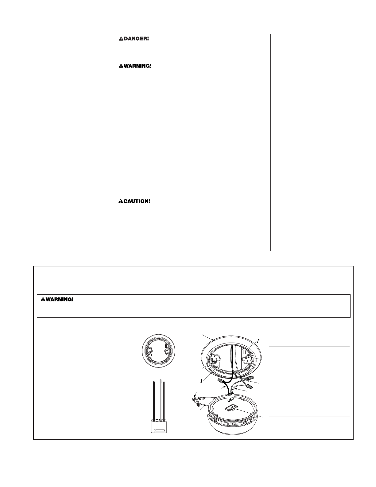
THE PARTS OF THIS SMOKE ALARM
The Mounting Bracket:
To remove the mounting bracket from the Smoke
Alarm base, hold the Smoke Alarm base firmly and
twist the mounting bracket counter
The mounting bracket installs onto the junction box.
It has a variety of screw slots to fit most boxes.
The Power Connector:
The power connector plugs into a power input block on
the Smoke Alarm. It supplies the unit with AC power
clockwise.
.
• The black wire is “hot.”
• The white wire is neutral.
• The orange wire is used for interconnect.
If you need to remove the power connector, insert a
flat screwdriver blade between the power connector
and the security tab inside the power input block.
Gently pry back the tab and pull the connector free.
The Parts of This Unit
1 Mounting Bracket
2 Mounting Slots
3 Locking Pins (break out of bracket)
4 Hot (Black) AC Wire
5 Neutral (White) AC Wire
6 Interconnect (Orange) Wire
7 Latch to Open Battery Compartment
8 Swing-Out Battery Compartment
9 Quick-Connect Power Connector
2
6
7
8
4
3
1
5
4
3
1
5
2
A
B
}
}
FOLLOW THESE INSTALLATION STEPS
The basic installation of this Smoke Alarm is similar whether you want
to install one Smoke Alarm, or interconnect more than one Smoke Alarm.
If you are interconnecting more than one Smoke Alarm, you MUST read
“Special Requirements For Interconnected Smoke Alarms” below before
you begin installation.
ELECTRICAL SHOCK HAZARD. Turn off power to the area where you
will install this unit at the circuit breaker or fuse box before beginning
installation. Failure to turn off the power before installation may result
in serious electrical shock, injury or death.
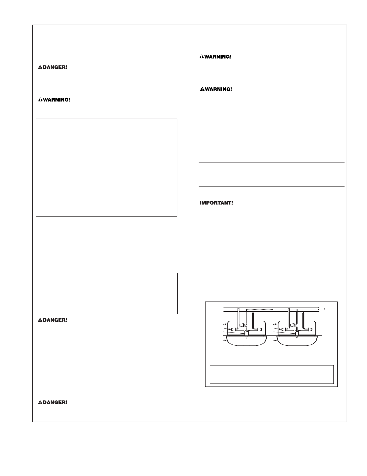
1. Using wire nuts, connect the power connector to the household wiring.
Improper wiring of the power connector or the wiring leading to the
power connector will cause damage to the Alarm and may lead to a
non-functioning Alarm.
STAND-ALONE ALARM ONLY:
• Connect the white wire on the power connector to the neutral wire
in the junction box.
• Connect the black wir
the junction box.
• Tuck the orange wire inside the junction box. It is used for
interconnect only.
INTERCONNECTED UNITS ONLY:
Strip off about 1/2” (12 mm) of the plastic coating on the orange
wire on the power connector.
• Connect the white wire on the power connector to the neutral wire
in the junction box.
• Connect the black wir
the junction box.
Connect the orange wire on the power connector to the interconnect
•
wire in the junction box. Repeat for each unit you are interconnecting.
Never connect the hot or neutral wires in the junction box to the orange
interconnect wire. Never cross hot and neutral wires between Alarms.
2. Remove the mounting bracket from the base, and attach it to the
junction box.
Plug the power connector into the back of the Smoke Alarm.
3.
Position the base of the Smoke Alarm over the mounting bracket and
4.
turn. The Alarm will remain secure over a wide rotation range to allow for
perfect alignment. When wall mounting, this will allow fine-tuning on the
positioning to compensate for misaligned wall studs and to keep the
wording level. The Alarm can be positioned over the bracket every 120°.
Rotate the Alarm until aligned properly.
5. Check all connections.
STAND-ALONE ALARM ONLY:
• If you are only installing one Smoke Alarm, restore power to the
junction box.
INTERCONNECTED UNITS ONLY:
• If you are interconnecting multiple Smoke Alarms, repeat steps
1-5 for each Smoke Alarm in the series. When you are finished,
restore power to the junction box.
e on the power connector to the hot wire in
e on the power connector to the hot wire in
9. For new construction, place supplied dust cover over Alarm to prevent
damage from dust and construction debris. When construction is complete, remove cover.
Smoke will not be able to reach smoke sensor while cover is in place.
Cover must be r
SPECIAL REQUIREMENTS FOR INTERCONNECTED SMOKE ALARMS
• Failure to meet any of the above requirements could damage the
units and cause them to malfunction, removing your protection.
• AC and AC/DC Smoke Alarms can be interconnected. Under AC
power, all units will alarm when one senses smoke. When power is
interrupted, only the AC/DC units in the series will continue to send
and receive signals. AC powered Smoke Alarms will not operate.
Interconnected units can provide earlier warning of fire than stand-alone units,
especially if a fire starts in a r
series senses smoke, all units will alarm. To determine which Smoke Alarm
initiated an alarm, see table:
During an Alarm:
On Initiating Alarm(s) Red LED(s) flashes (flash) rapidly
On All Other Alarms Red LED is Off
After an Alarm (Latching):
On Initiating Alarm(s) Green LED(s) On for 2 seconds/Off for 2 seconds
On All Other Alarms Green LED(s) On, Red LED(s) is Off
Compatible Interconnected Units
Interconnect units within a single family residence only. Otherwise all households will experience unwanted alarms when you test any unit in the series.
connected units will only work if they are wired to compatible units and
Inter
all requirements are met. This unit is designed to be compatible with:
First Alert®Smoke Alarm Models SA4120, SA4121B, SA100B and BRK
Electronics®Smoke Alarm Models 9120, 9120B, SC6120B, SC9120B, 7010,
7010B, 100S, 4120, 4120B, 4120SB, RM3 (Relay Module); BRK Electronics
CO Alarm Models CO5120BN, CO5120PDBN; BRK Electronics®Heat Alarm
Models HD6135F and HD6135FB.
Interconnected units must meet ALL of the following requirements:
• A maximum of 18 compatible units may be interconnected
(Maximum of 12 Smoke Alarms).
The same fuse or circuit breaker must power all interconnected units.
•
• The total length of wire interconnecting the units should be less than
1000 feet (300 meters). This type of wire is commonly available at
Hardware and Electrical Supply stores.
All wiring must conform to all local electrical codes and NFPA 70 (NEC).
•
Refer to NFPA 72, NFPA 101, and/or your local building code for further
connection requirements.
emoved!
emote area of the dwelling. If any unit in the
®
ELECTRICAL SHOCK HAZARD. Do not restore power until all Smoke
Alarms are completely installed. Restoring power before installation is
complete may result in serious electrical shock, injury or death.
6. Make sure the Smoke Alarm is receiving AC power. Under normal
operation, the Green power indicator light will shine continuously.
7. If the Green power indicator light does not light, TURN OFF POWER TO
THE JUNCTION BOX and recheck all connections. If all connections
are correct and the Green power indicator still does not light when you
restore the power, the unit should be replaced immediately.
8. Single Station Alarms: Test each Smoke Alarm. Press and hold the
est/Silence button until the unit alarms.
T
Interconnected Alarms: Press and hold the Test/Silence button until
the unit alarms. All interconnected Alarms should sound. The other
Alarms sounding only tests the inter
It does not test each Alarm’s operation. You must test each Alarm
individually to check if the Alarm is functioning properly.
If any unit in the series does not alarm, TURN OFF POWER and recheck
connections. If it does not alarm when you restore power, r
immediately.
connect signal between Alarms.
eplace it
3
A. Unswitched 120VAC
60 Hz source
1. Smoke Alarm
2. Ceiling or Wall
3. Power Connector
B. To additional units; Maximum = 18 total
(Maximum 12 Smoke Alarms)
4. Wire Nut
5. Junction Box
6. Neutral Wire (Wht)
7. Interconnect Wire
(Orange)
8. Hot Wire (Blk)
 Loading...