

Gravely 250Z, 260Z User Manual


TABLE OF CONTENTS
Section 1 - Introduction . . . . . . . . . . . . . . . . . . 1-3
1.1 The Manual . . . . . . . . . . . . . . . . . . . . . . . . 1-3
1.2 Service and Replacement Parts . . . . . . . . 1-3
1.3 Product Registration . . . . . . . . . . . . . . . . . 1-3
1.4 Unauthorized Replacement Parts . . . . . . . 1-3
1.5 Disclaimer . . . . . . . . . . . . . . . . . . . . . . . . . 1-3
1.6 Technical Service Communications . . . . . . 1-3
1.7 Preparation . . . . . . . . . . . . . . . . . . . . . . . . 1-3
Section 2 - Safety . . . . . . . . . . . . . . . . . . . . . . . 2-4
2.1 Safety Alerts . . . . . . . . . . . . . . . . . . . . . . . 2-4
2.2 Signal Words . . . . . . . . . . . . . . . . . . . . . . . 2-4
2.3 Notations . . . . . . . . . . . . . . . . . . . . . . . . . . 2-4
2.4 Practices and Laws . . . . . . . . . . . . . . . . . . 2-4
2.5 Required Operator Training . . . . . . . . . . . . 2-4
2.6 Safety Rules. . . . . . . . . . . . . . . . . . . . . . . . 2-4
Section 3 - Specifications . . . . . . . . . . . . . . . . 3-7
Section 4 - General Maintenance
& Adjustments . . . . . . . . . . . . . . . . . . . . . . . 4-8
4.1 Controls and Features . . . . . . . . . . . . . . . . 4-8
4.2 Service Position - 260Z . . . . . . . . . . . . . . . 4-9
4.3 Service Position - 250Z . . . . . . . . . . . . . . . 4-9
4.4 Moving the Unit-Engine Not Running. . . . . 4-9
4.5 Cleaning and Storage . . . . . . . . . . . . . . . . 4-9
4.6 Filling The Fuel Tank . . . . . . . . . . . . . . . . 4-10
4.7 Fasteners. . . . . . . . . . . . . . . . . . . . . . . . . 4-10
4.8 General Lubrication . . . . . . . . . . . . . . . . . 4-10
4.9 Basic Engine Maintenance . . . . . . . . . . . 4-11
4.10 Belts. . . . . . . . . . . . . . . . . . . . . . . . . . . . 4-11
4.11 Tires. . . . . . . . . . . . . . . . . . . . . . . . . . . . 4-12
4.12 Mower Blades . . . . . . . . . . . . . . . . . . . . 4-12
4.13 Steering Control Neutral Adjustment . . . 4-13
4.14 Adjusting Control Levers . . . . . . . . . . . . 4-13
4.15 Adjusting The Parking Brake . . . . . . . . . 4-14
4.16 Adjusting The Unit To Track Straight . . . 4-14
4.17 Leveling The Mower Deck . . . . . . . . . . . 4-15
Section 5 - Engine. . . . . . . . . . . . . . . . . . . . . . 5-16
5.1 Engine Troubleshooting . . . . . . . . . . . . . . 5-16
5.2 Removing the Engine. . . . . . . . . . . . . . . . 5-17
5.3 Installing The Engine . . . . . . . . . . . . . . . . 5-17
5.4 Electric Clutch . . . . . . . . . . . . . . . . . . . . . 5-17
Section 6 - Drive Train . . . . . . . . . . . . . . . . . . 6-18
6.1 Checking The Hydraulic Fluid Level. . . . . 6-18
6.2 Changing Hydraulic Fluid And Filter . . . . 6-18
6.3 Hydraulic Drive Flow Test. . . . . . . . . . . . . 6-18
6.4 Replacing The Hydraulic Pump . . . . . . . . 6-19
6.5 Replace Wheel Motor . . . . . . . . . . . . . . . 6-20
6.6 Hydraulic Deck Lift Pressure Test . . . . . . 6-21
6.7 Replace Lift Valve . . . . . . . . . . . . . . . . . . 6-21
6.8 Hydraulic Diagram . . . . . . . . . . . . . . . . . . 6-22
Section 7 - Mower Deck . . . . . . . . . . . . . . . . . 7-23
7.1 Mower Deck. . . . . . . . . . . . . . . . . . . . . . . 7-23
7.2 Anti-Scalp Rollers . . . . . . . . . . . . . . . . . . 7-23
Section 8 - Front Suspension . . . . . . . . . . . . 8-24
Section 9 - Electrical. . . . . . . . . . . . . . . . . . . . 9-25
9.1 Tools. . . . . . . . . . . . . . . . . . . . . . . . . . . . . 9-25
9.2 Electrical Measurements . . . . . . . . . . . . . 9-25
9.3 Battery . . . . . . . . . . . . . . . . . . . . . . . . . . . 9-26
9.4 Switches. . . . . . . . . . . . . . . . . . . . . . . . . . 9-28
9.5 Solenoid and Relays . . . . . . . . . . . . . . . . 9-29
9.6 Fuses . . . . . . . . . . . . . . . . . . . . . . . . . . . . 9-29
9.7 Diodes and Rectifiers. . . . . . . . . . . . . . . . 9-30
9.8 Wiring Diagrams . . . . . . . . . . . . . . . . . . . 9-31
2
SECTION 1 - INTRODUCTION
1.1 THE MANUAL
The purpose of this manual is to provide complete
instructions for service, maintenance, disassembly,
repair, and installation of the mechanical components
for the Promaster 260Z and 250Z.
Dealer trained service personnel should use this
manual as a supplement to and reminder of the training
sessions conducted by the company.
Read all information for servicing a part or system
before repair work is started to avoid needless
disassembly.
Operation
Before operation of the unit, carefully and completely
read manuals supplied with the unit. The contents will
provide you with an understanding of safety
instructions and controls during normal operation and
maintenance.
Safety Messages
For your safety and the safety of others always read,
understand, and follow all DANGER, WARNING, and
CAUTION messages found in manuals and on safety
decals.
Directional Reference
All reference to left, right, front, or rear are given from
the operator in the operator position and facing the
direction of forward travel.
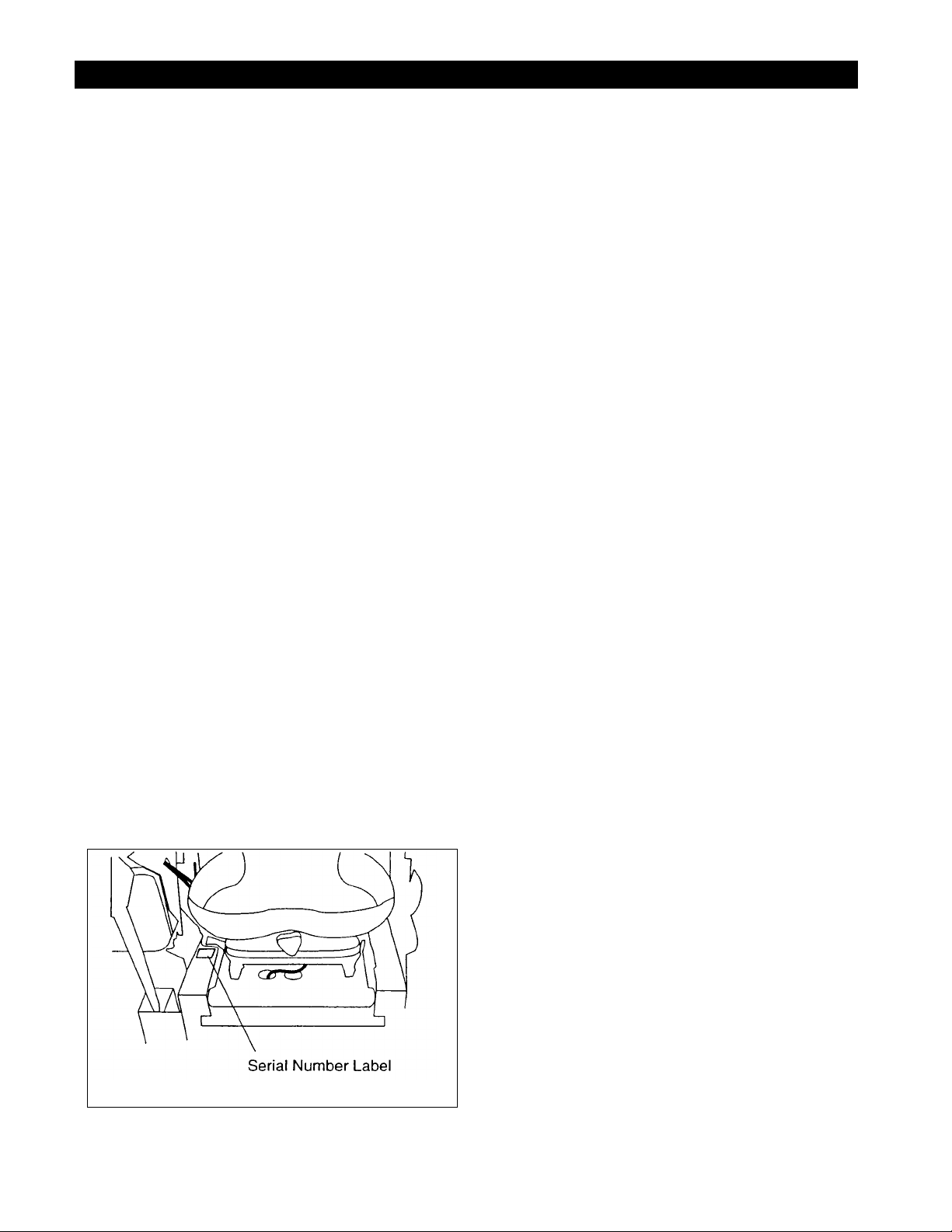
1.2 SERVICE AND REPLACEMENT PART S
When ordering publications, replacement parts, or
making service inquiries, know the Model and Serial
numbers of your unit and engine.
Numbers are located on the product registration form in
the unit literature package. They are printed on a serial
number label, located on the frame of your unit.
1.3 PRODUCT REGISTRATION
A warranty registration card must be filled out, signed,
and returned at time of purchase. This card activates
the warranty. Claims meeting requirements during
limited warranty period will be honored.
1.4 UNAUTHORIZED REPLACEMENT
PARTS
Use only Gravely replacement parts. The replacement
of any part on this vehicle with anything other than a
Gravely authorized replacement part may adversely
affect the performance, durability, or safety of this unit
and may void the warranty. Gravely disclaims liability
for any claims or damages, whether warranty, property
damage, personal injury, or death arising out of the use
of unauthorized replacement parts.
1.5 DISCLAIMER
Gravely reserves the right to discontinue, make
changes to, and add improvements upon its products
at any time without public notice or obligation. The
descriptions and specifications contained in this
manual were in effect at printing. Equipment described
within this manual may be optional. Some illustrations
may not be applicable to your unit.
1.6 TECHNICAL SERVICE
COMMUNICATIONS
Ariens Technical Service communicates information to
the field using Service Letters, Service Bul letins,
Product Notices, and Campaigns. Each communication
signifies a type of information and priority . The dealer is
responsible to carry out the direc ti ve provided in the
communication. The types of communication are:
Service Letter
dealer. Technical information on how to service the
product and product improvements.
Service Bulletin
resolve certain issues or a notification of a policy
change.
Product Notices
located in a certain region. This is a limited distribution
to only those who received the product involved.
Campaigns
products must be updated and are tracked by the
factory until all units are corrected.
- General technical information for the
- Notification to update products to
- Notification of limited product
- Notification of a safety related issue. All
Figure 1
1.7 PREPARATION
Before starting any removal of parts, proper
preparation is very important for efficient work. A clean
work area at the start of each job will allow you to
perform service repairs easily and quickly.
1 - 3
To reduce the incidence of misplaced tools or parts,
place removed components with all attaching hardware
in the disassembly order on a clean work surface.
Organization is a key part of proper reassembly.
SECTION 2 - SAFETY
Tools, instruments, and parts needed for the job should
be gathered before work is started. Interrupting a job to
locate tools or parts is a needless delay.
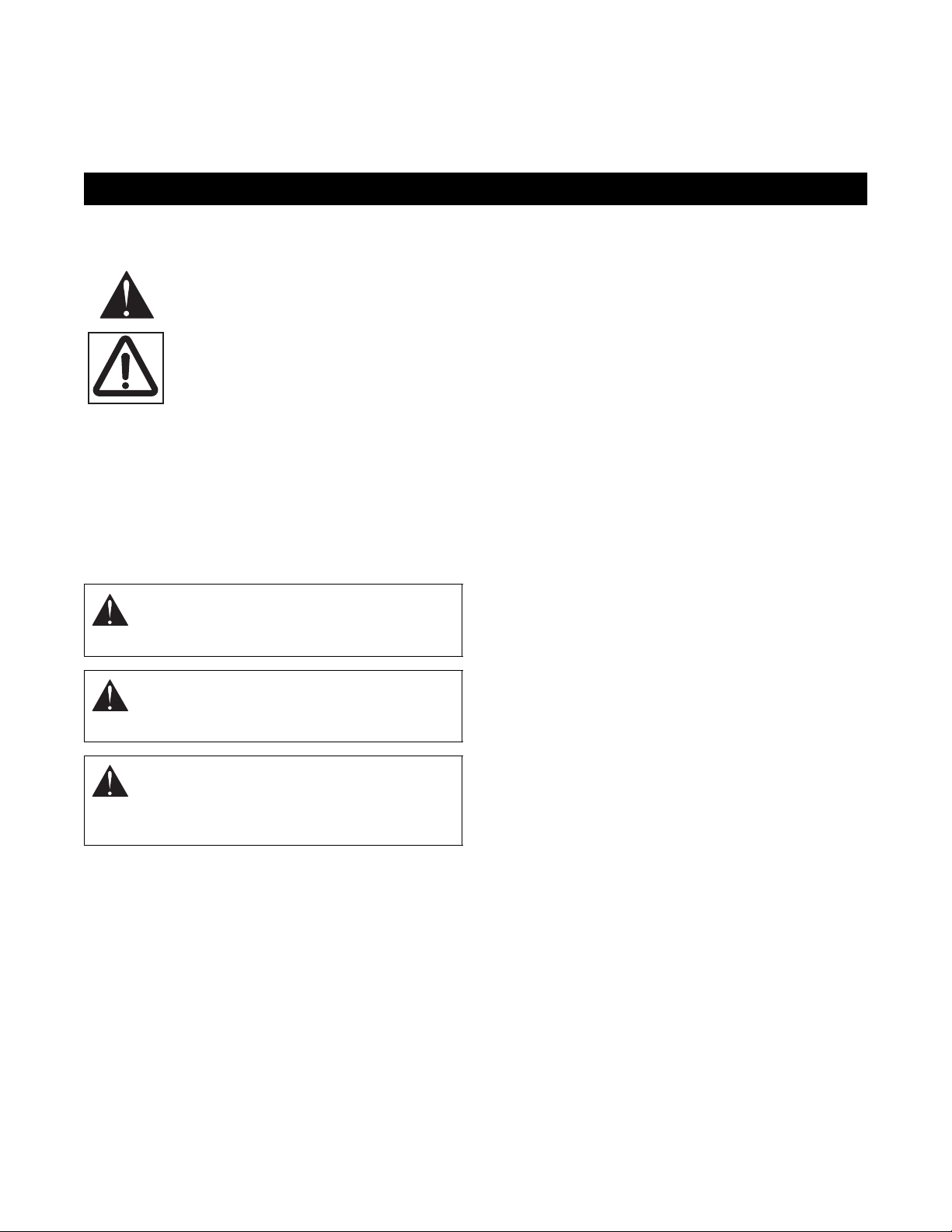
2.1 SAFETY ALERTS
Look for these symbols to point out
important safety precautions. They
mean:
Attention!
Personal Safety Is Involved!
Become Alert!
Obey The Message!
2.2 SIGNAL WORDS
The safety alert symbol is used in decals on the unit
and with proper operation procedures in this manual.
They alert you to the existence and relative degree of
hazards.
Understand the safety message. It contains important
information about personal safety on or near the unit.
DANGER:
SITUATION! If not avoided, WILL RESULT in
death or serious injury.
WARNING:
SITUATION! If not avoided, COULD RESULT
in death or serious injury.
CAUTION:
SITUATION! If not avoided, MAY RESULT in
minor or moderate injury. It may also be used
to alert against unsafe practices.
IMMINENTLY HAZARDOUS
POTENTIALLY HAZARDOUS
POTENTIALLY HAZARDOUS
2.3 NOTATIONS
NOTE:
ation and maintenance practices.
IMPORTANT:
required to prevent damage to unit or attachment.
General reference information for proper oper-
Specific procedures or information
2.4 PRACTICES AND LAWS
Practice usual and customary safe working
precautions, for the benefit of yourself and others.
Understand and follow all safety messages. Be alert to
unsafe conditions and the possibility of minor,
moderate, or serious injury or death. Learn applicable
rules and laws in your area.
2.5 REQUIRED OPERATOR TRAINING
Original purchaser of this unit was instructed by the
seller on safe and proper operation. If unit is to be used
by someone other than original purchaser; loaned,
rented or sold, ALW AYS provide the Operator’s Manual
and any needed safety training before operation.
2.6 SAFETY RULES
Walk Around Inspection
Complete a walk around inspection of unit and work
area to understand:
• Work area.
• Your unit.
• All safety decals.
Wo rk Ar ea
AL W AYS check overhead and side clearances carefully
before operation. ALWAYS be aware of traffic when
operating along streets or curbs.
ALWAYS keep hands and feet within the limits of the
unit.
Keep children, people, and animals away. Keep
children out of work area and under watchful care of a
responsible adult.
Keep area of operation clear of all toys, pets, and
debris. Obje cts ca n ca us e vehicle instabilit y and in ju ry.
Check for weak spots on dock, ramps or floors. Avoid
uneven work areas and rough terrain. Stay alert for
hidden hazards.
DO NOT run engine in an enclosed area. Always
provide good ventilation.
Unit
ALWAYS keep protective structures, guards, and
panels in good condition, in place and securely
fastened. NEVER modify or remove safety devices.
Check Safety Interlock System for proper operation
daily (see Operation section). Do not operate unless
system operates properly.
2 - 4

Operation
Understand:
• How to operate all controls
• The functions of all controls
• How to STOP in an Emergency
• Speed ranges
Do not operate any of the control levers or power takeoff unless both feet are resting on the platform.
DO NOT travel at too fast a rate. DO NOT change
engine governor settings or over-speed engine.
Always back up slowly. Always look down and behind
before and while backing.
Never leave a runnin g unit unatt end ed. ALWAYS shut
off power take off, lower throttle setting, and stop
engine before leaving unit. ALWAYS remove key to
prevent unauthorized use.
Never carry passengers on any part of unit.
Av oid une v en and rough terrain. DO NOT oper ate near
drop offs, ditches, or embankments. Unit can suddenly
turn over if a wheel is over the edge of a cliff or ditch, or
if an edge caves in.
If tires lose traction, turn off power take off and proceed
slowly straight down slope. Avoid wet surfaces.
Avoid parking on a slope. If necessary, use wheel
chocks.
DO NOT leave unit unattended on a slope. ALWAYS
use wheel chocks when leaving unit.
ALWAYS operate unit in good visibility and light.
Fuel is highly flammable and its vapors can explode.
Use ONLY approved fuel containers.
NO Smoking!
NO Sparks!
NO Flames!
Allow engine to cool before servicing.
NEVER fill fuel tank when engine is running, hot, or
unit is indoors.
Abnormal Vibrations are a warning of trouble. Striking a
foreign object can damage unit. Immediately stop unit
and engine. Remove key and wait for all moving parts
to stop. Remove wire from spark plug. Inspect unit and
make any necessary repairs before restart.
Hazardous Slopes
DO NOT operate on steep slopes. Avoid operating on
slopes. When you must operate on a slope, travel up
and down the slope. Never operate across a slope.
Never operate on a slope greater than 10 degrees.
Child Safety
NEVER allow children to operate or play on or near
unit. Be alert and shut off unit if children enter area.
• Only trained adults may operate unit.
• Training includes actual operation.
• Clearly understa nd ins tructions.
• Be alert! Conditions can change.
NEVER operate unit after or during the use of
medication, drugs or alcohol. Safe operation requires
your complete and unimpaired attention at all times.
NEVER allow anyone to operate the unit when their
alertness or coordination is impaired.
DO NOT operate unit without wearing adequate outer
garments. Wear adequate safety gear and protective
gloves. Wear proper footwear to improve footing on
slippery surfaces.
Protect eyes, face, and head from objects that may be
thrown from unit. Wear appropriate hearing protection.
Avoid Sharp Edges. Sharp edges can cut. Moving
parts can cut or amputate fingers or a hand. Wear
gloves to service unit when handling sharp edges.
ALWAYS keep hands away from any pinch points.
ALWAYS keep hands and feet away from all moving
parts during operation. Moving parts can cut off body
parts.
DO NOT touch unit parts which might be hot from
operation. Allow parts to cool before attempting to
maintain, adjust, or service.
Controls
Come to a complete stop before reversing.
Never jerk the control levers. Alw a ys use a steady ev en
action to achieve smooth control.
Always be aware of obstructions that may cause injury
to operator or damage to the unit.
Maintenance
ALWAYS maintain unit in safe operating condition.
Damaged or worn out muffler can cause fire or
explosion.
Check the conditions of the unit at the end of each day
and repair any damage or defects.
ALWAYS block wheels and know all jack stands are
strong and secure and will hold weight of unit during
maintenance.
Keep nuts and bolts tight and keep equipment in safe
operating conditions.
Before maintenance, adjustments, or service (except
where specifically recommended), shut off engine.
Allow hot parts to cool.
Keep unit free of dirt, stones, and other debris. Clean
up oil or fuel spills.
Personal Safety
Read and obey all warning, caution, and instructions
on the unit and in provided manuals.
2 - 5

Storage
DO NOT store unit inside a building with fuel in the fuel
tank where any ignition sources are present. Allow unit
to cool completely.
ALWAYS clean unit before extended storage. See
Engine Manual for proper storage.
Battery
Avoid Electric Shock. DO NOT reverse battery
connections.
Explosive Gases! Poisonous battery fluid contains
sulfuric acid and its contact with skin, eyes, or clothing
can cause severe burns.
No flames. No sparks. No smoking near battery.
Always wear safety glasses and protective gear near
battery.
o
DO NOT TIP battery beyond a 45
direction.
ALWAYS KEEP BATTERIES OUT OF REACH of
children.
angle in any
Transport
Use extra care when loading or unloading unit onto
trailer or truck. Secure unit chassis to transport vehicle.
NEVER secure from rods or linkages that could be
damaged.
DO NOT transport with attachment in raised position.
Lower attachment when unit is parked or stored unless
a positive mechanical lock is used.
Attachments and Accessories
Use only attachments or accessories designed for your
unit.
2 - 6

SECTION 3 - SPECIFICATIONS
Model Number 992020 and 022 992018 992021 992023 992024
Model PM260Z 25 HP
Kohler with
60" deck
Length - cm (in) 229 (90)* 221 (87) 229 (90)*
Height - cm (in) 127 (50)
Width - cm (in) 185 (73) 160 (63) 185 (73)
Weight Actual - kg (lbs) 510 (1125) 499 (1100) 500 (1103) 490 (1080) 511 (1128)
Battery 12 volt
Brakes Hydro/Dynamic Disk - Parking
Turning Radius 0
Tire Size Fron t
Rear
Engine - manufacturer Kohler Kohler Robin Briggs & Stratton Robin
Model Number CV25S CV25S EH65V 35177 EH65V
Cycle 4
Engine Power HP (KW/min
Starting System Electric
Fuel Tank Capacity 9 gals. US (34 liters)
Fuel See Engine Manual
Idle RPM 1800
Governed RPM 3600
Air Cleaner Large Capacity Dual Element
Cooling Capacity Air Cooled
Engine Oil Type See Engine Ma nual
Spark Plug Gap See Engine Manual
Transmission Hydrostatic Drive
Speed - Forward Max.
Reverse Max.
Transmission Lube Mobil 1 15W-50 Synthetic
Drive Clutch Hydrostatic
Tire Pressure Front
Rear
Lift System Hydr au lic
Power Take Off Electric PTO Clutch/Brake
Mower Deck High Performance
Cutting Width - cm (in) 152 (60) 127 (50) 152 (60)
Cutting Height - cm (in) 2.5 - 12.7 (1 - 5)
Cut Increments - cm (in) Infinite between 2.5 - 12.7 (1 - 5)
-1
)
25 HP
(18.4 KW/min -1)
PM260Z 25 HP
Kohler with
50" deck
15 x 6 - 6
23 x 10.5 - 12
25 HP
(18.4 KW/min -1)
PM260Z 22 HP
Robin with
50" deck
22 HP
(16.2 KW/min -1)
9 MPH
4.5 MPH
20-25 psi
12-15 psi
PM250Z 20HP
Briggs &
Stratton with
50" deck
15 x 6 - 6
23 x 8.5 - 12
20 HP
(14.7 KW/min -1)
PM260Z 22 HP
Robin with
60" deck
15 x 6 - 6
23 x 10.5 - 12
22 HP
(16.2 KW/min -1)
3 - 7
SECTION 4 - GENERAL MAINTENANCE & ADJUSTMENTS
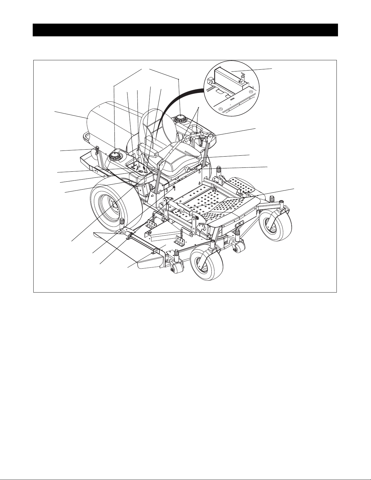
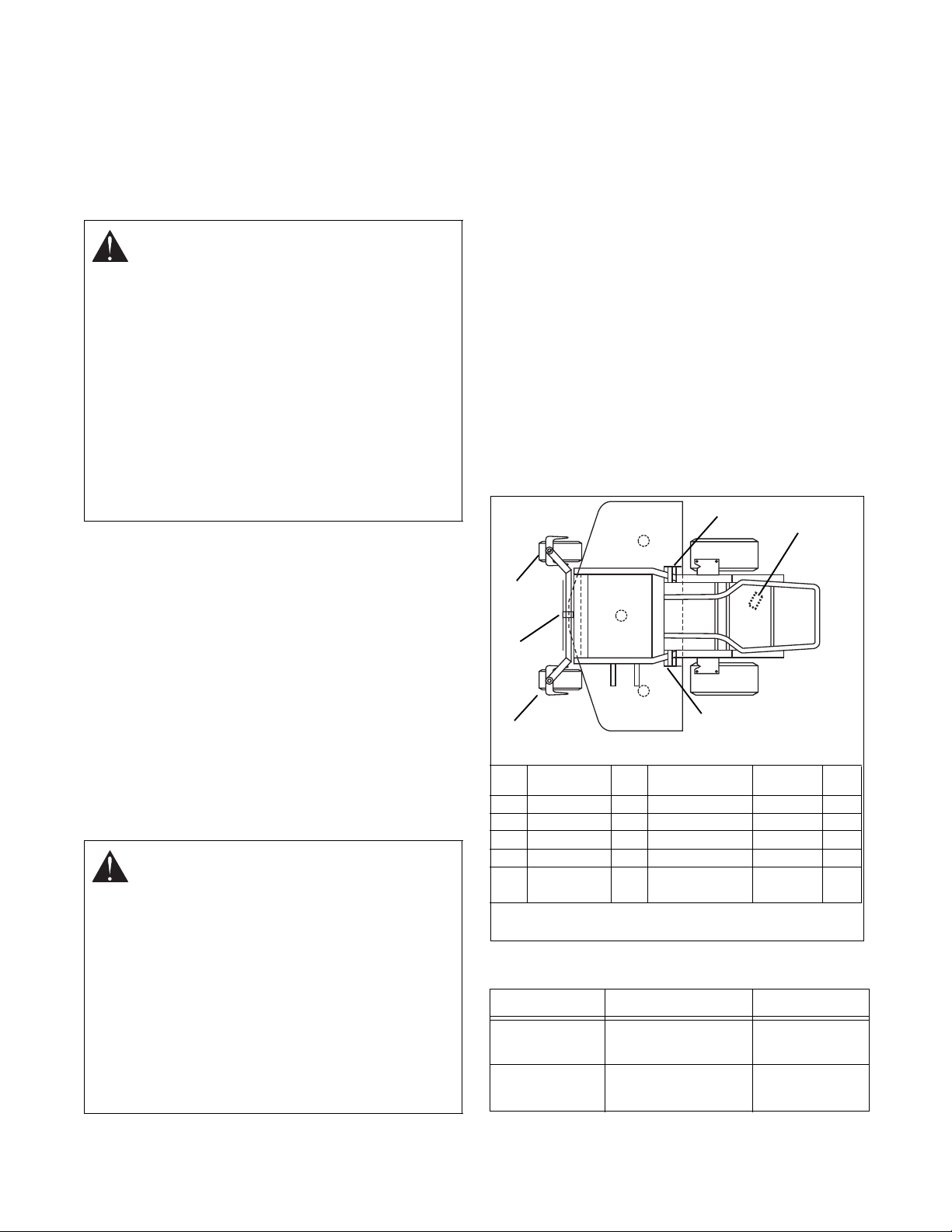
4.1 CONTROLS AND FEATURES
8
11
10
9
7
19
6
5
4
12
13
15
18
14
16
17
3
2
20
1. Mower Deck with Chute Deflector
2. Fuel Shut Off Valve
3. Parking Brake
4. Battery
5. Hour Meter
6. Oil Pressure Indicator
7. Engine Frame and Hood (260Z)
8. Fuel Tanks and Caps
9. Choke Control
10. Throttle Control
* Serial No. 010000 and up are 221 (87)
1
OF1722
Figure 2
11. Ignition Sw itch
12. Power Take Off (PTO) Switch
13. Steering Levers
14. Mower Lift Lever
15. Seat Adjustment Lever
16. Seat Suspension Adjustment Knob (260Z)
17. Height of Cut Indicator
18. Hydraulic Oi l Reservoir
19. Engine Hood Latch (260Z)
20. Foot Board Latch
4 - 8
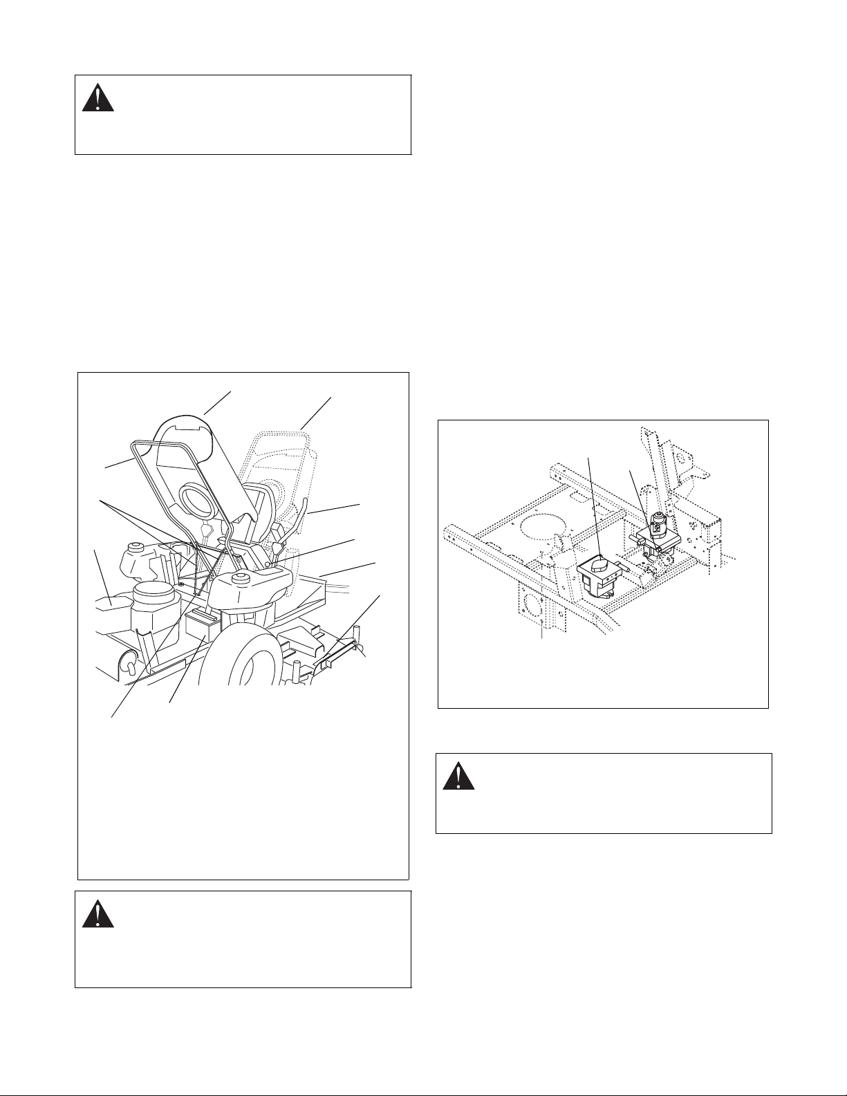
4.2 SERVICE POSITION - 260Z
1
2
1. Left Bypass Valve Lever
2. Right Bypass Valve Lever
Figure 4
OF1730
WARNING:
ALWAYS block wheels and know
that jack stands or blocks used are stable,
strong, or secure and will hold the weight of
the unit during maintenance.
To ensure the unit is positioned in the proper service
position:
1. Place unit on a flat level surface. ALWAYS stop
engine. Assure unit is secure and will not tip over.
Strap and clamp onto lift if used.
2. Place steering levers in neutral position and set
parking brake.
3. Unhook hood latches.
4. Firmly grasp engine frame and cover. Lift to
desired service position (Figure 3).
7
8
Daily Service Position:
Place engine hood prop rod
into service slot. Assure rod is engaged in slot properly .
Full Service Position:
Slowly release frame after seat
contacts foot board. Use care and be sure of your
footing. Do not step on mower deck.
5. When service is complete, lower hood and secure
with latches.
4.3 SERVICE POSITION - 250Z
Firmly grasp seat frame handle and lift past vertical.
Lay inverted seat on foot rest. When service is
complete, return seat to upright position.
4.4 MOVING THE UNIT-ENGINE NOT
RUNNING
To move the unit without the engine running, rotate the
bypass valve levers located on the pumps toward the
center of the tractor approximately 1/2 turn using a
wrench. Levers must be returned to their original
position in order to operate the unit (Figure 4).
4
5
9
6
1. Steering Levers
2. Parking Brake
3. Footboard
4. Engine Hood & Frame
5. Engine Hood Prop Rod
6. Service Slot
11
7. Daily Service Position
8. Full Service Position
9. Engine
10. No Step Decal
11. Battery
Figure 3
CAUTION:
WHEN OPENING ENGINE
COVER, USE CARE TO PROPERLY
ENGAGE PROP INTO SLOT. Be sure footing
is secure to accommodate weight shift of
hood when rotating to full service position.
1
2
3
10
4.5 CLEANING AND STORAGE
OF1811
WARNING:
can cut. Movement of parts can cut off fingers
or a hand. Wrap blades, wear gloves, and use
extreme caution when servicing.
IMPORTANT:
outdoors to help prevent sealed bearing rust or
corrosion. Water can seep into sealed bearings and
reduce component life. Bearings are sealed against dirt
and debris only.
A unit that is excessively dirty should be cleaned before
work starts. Cleaning will occasionally uncover trouble
sources. Dirt and abrasive dust reduce the efficient
work life of parts and can lead to costly replacement.
AVOID SHARP EDGES which
Never spray unit with water or store unit
4 - 9
When taking unit out of extended storage:
REF LUBRICA TION QTY DESCRIPTION-
LOCA TION
INTERV AL
REF
1 GREASE 2 CASTER PIVOT 50 Hrs. 1
2 GREASE 1 AXLE PIVOT 400 Hrs 2
3 GREASE 2 PUSH ARM PIVOT 50 Hrs 3
4 GREASE 1 PUSH ARM PIVOT 50 Hrs 4
OIL ALL PIVOT POINTS,
PIN CONNECTIONS
50 Hrs
OF1791
1
2
2
3
3
4
Figure 5
1. Check for any damage or loose parts. Repair,
replace, or tighten hardware before operation,
especially blade attachment bolts.
2. If a preservative fluid was used in fuel tank, drain
and discard. Fill fuel tank with fresh new fuel.
4.6 FILLING THE FUEL TANK
EXPLOSIVE VAPORS and FLAMMABLE
FUEL can result in serious injury or death.
Handle fuel with care. ALWAYS use an
approved fuel container.
No Smoking!
No Lighted Materials!
No Open Flame!
Allow engine to cool.
Use caution with fuel. Fuel is very flammable.
Keep fuel in a clean and tight container. Keep
fuel away from fire or heat. Neve r put fuel in
the fuel tank while the engine is running or
hot. Clean up any spilled fuel before starting
the engine.
4.7 FASTENERS
Each day before operating, check mower blade
mounting hardware and all other fasteners. Replace
fasteners that are missing or damaged. Tighten all nuts
and bolts to their correct torque value.
4.8 GENERAL LUBRICATION
IMPORTANT:
lubrication.
Lube fitting locations are:
-each deck push arm (2)
-Hydro Idler (1)
-front ax le pivot (1)
Apply Sten Mix Hi-Temp Grease or equivalent to the
lube fittings. Order P/N: 00036700- ten pack of 14 oz.
cartridges.
When using Sten Mix Hi-Temp Grease for the first time,
all components should be thoroughly cleaned prior to
lubricating.
Apply oil at all pivot points and pin connections.
Wipe each fitting clean before and after
Add fuel to the tank as needed. See your Engine
Manual for correct type and grade of fuel.
To add fuel to the fuel tank:
1. Refuel the unit only in a well ventilated, open area.
2. Stop the engine.
3. Clean the fuel cap and the area around the fuel
cap to prevent dirt from entering the fuel tank.
Remove the cap from the fuel tank.
4. Fill the fuel tank. Be careful not to spill the fuel. Do
not overfill, allow for fuel expansion. Stop filling
when fuel is about 1” below the bottom of the neck.
5. Install the cap on the fuel tank and tighten.
6. Clean up any spilled fuel before starting the
engine.
WARNING:
is extremely flammable and highly explosive.
POTENTIAL HAZARDOUS! Fuel
Personal injury and property damage may
result if not handled properly.
• Fill the fuel tank outdoors in an open area.
Do not fill when the engine is hot. Wipe up
any fuel spills.
• Never fill the fuel tank completely full.
Empty space in tank allows fuel to
expand.
• Never smoke when handling fuel. Stay
away from open flames. Fuel fumes can
be ignited by sparks.
Description Use Interval
Grease fittings Sten Mix Hi-Temp
grease or equivalent
Hydraulic
system
Mobil 15W50
synthetic oil
4 - 10
50 hrs. running
time
500 hrs running
time
4.9 BASIC ENGINE MAINTENANCE
See your engine manual and Section 5 of this manual
for detailed information on the operation and
maintenance of your engine.
1. Each day before operating, check the level of the
oil in the engine. Never operate the engine when
the oil level is below the add mark.
2. Each day before operating, check the air cleaner
element. Dirt can decrease the flow of air to the
engine.
3. Each day before operating, check the air cooling
system on the engine. Debris can decrease the
flow of air cooling the engine.
4. Follow the maintenance instructions in your engine
manual concer ni ng oil and filte r ch ange s.
4.10 BELTS
WARNING:
amputate body parts. ALWAYS wait for
moving parts to stop before performing
maintenance or service.
CAUTION:
may result in injury and/or damage to the unit.
Check belts for excessive wear or cracks
often.
Belt Access
1. Properly stop and park unit (refer to Owner’s
Manual).
2. Lower the mower.
3. Place seat in most rearward position.
4. Remove belt covers.
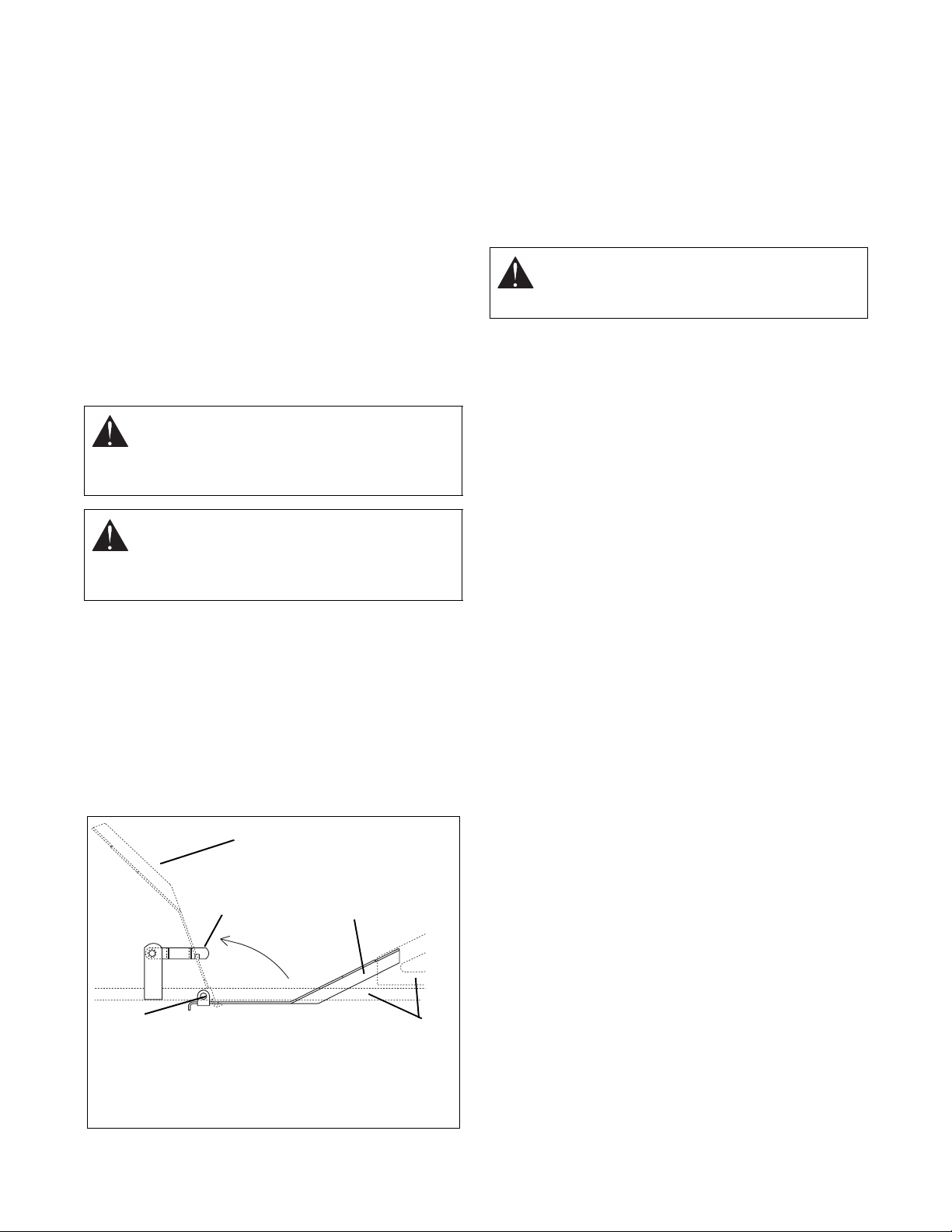
5. Place foot board in open position (Figure 6).
6. Secure raised footboard with latch.
MOVING PARTS can cut or
DAMAGED OR WORN BELTS
Replacing Mower Belts
NOTE:
belt.
Long belt must be removed to remove short
1. Roll long belt off left blade spindle and remove from
deck.
2. Roll short belt off right blade spindle and remove
from deck. Idler pivot bolt must be loosened slightly
to gain clearance to remove belt from under idler
pulley (Figure 7).
CAUTION:
Use care when releasing idler
spring tension. Keep body parts well away
from idlers when performing this operation.
3. Arrange new mower belt(s) on deck (short belt
first). Retighten short belt idler pivot bolt. Install
belts on sheaves. Roll belts onto blade sheave last.
4. Replace belt covers and return foot board to closed
position.
Replacing the Hydro Pump Belt
1. Properly stop and park unit (refer to unit Owner’s
Manual).
2. Remove the mower belt from the mower clutch
sheave. See Replacing Mower Belts.
3. Remove old hydro pump belt by rolling belt off right
hand hydrostat sheave first (Figure 8).
4. Install new pump belt by positioning belt on
sheaves. Roll belt onto right hand hydrostat sheave
last.
5. Put the mower belt back on mower clutch sheave.
See Replacing Mower Belts.
5
4
1. Footboard in open
position
2. Footboard in closed
position
1
Figure 6
2
3
3. Support Frame
4. Pivot
5. Latch
OF1802
4 - 11
 Loading...