

Gravely 22531, 23075, 23076 User Manual
CLARKE-GRAVELY CORPORATION
A Studebaker-Worthington Company
~GRAVELY
e
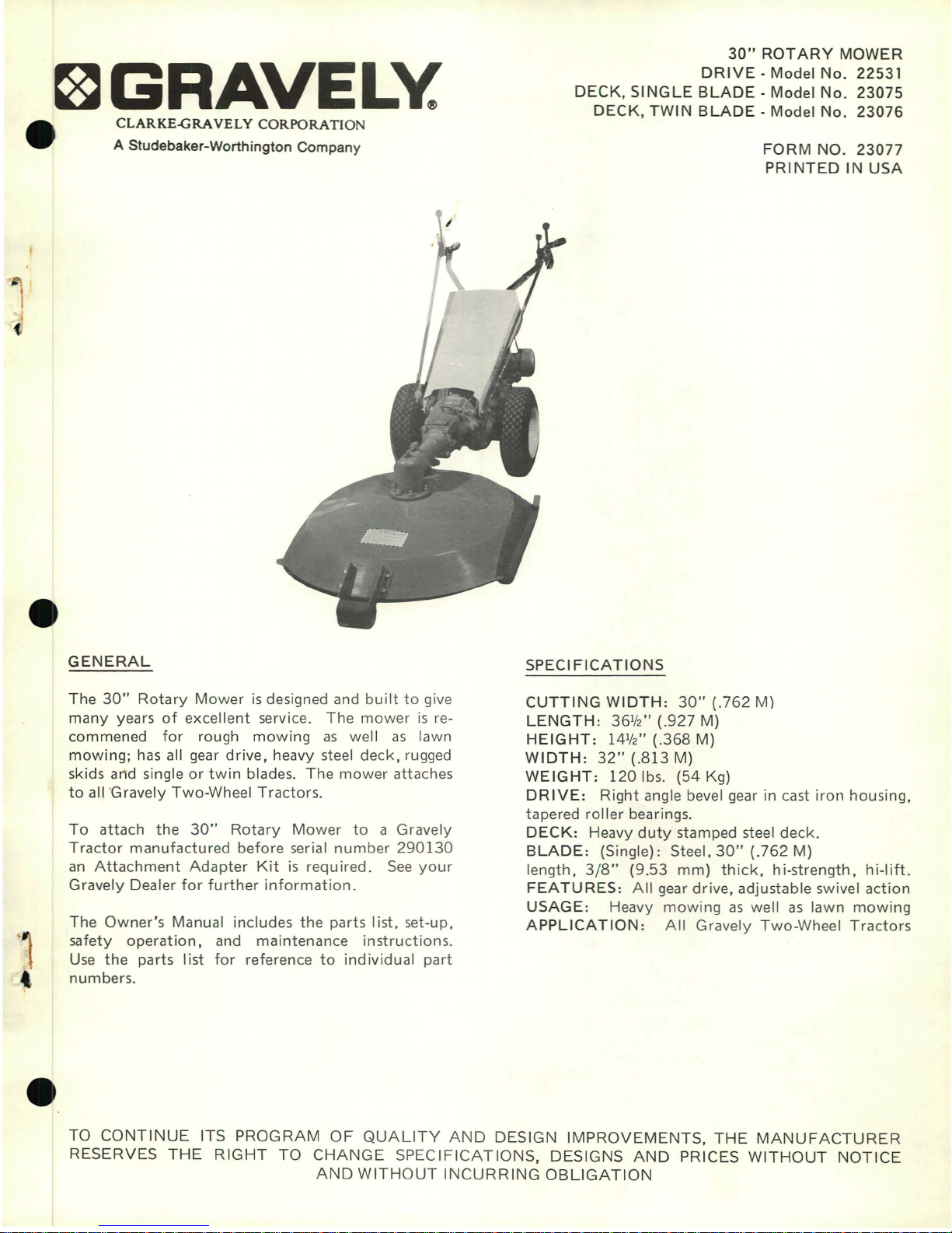
30"
ROTARY
MOWER
DRIVE·
Model
No.
22531
DECK,
SINGLE
BLADE·
Model
No.
23075
DECK,
TWIN
BLADE-Model
No.
23076
FORM
NO.
23077
PRINTED
IN
USA
GENERAL
The
30"
Rotary
Mowerisdesigned and
builttogive
many
years
of
excellent
service.
The
mowerisre-
commened
for
rough
mowing
as
well
as
lawn
mowing;
has all gear
drive,
heavy steel
deck,
rugged
skids and single
or
twin
blades.
The
mower
attaches
to
all·Gravely Two-Wheel
Tractors.
To
attach
the
30"
Rotary
Mower
to
a Gravely
Tractor
manufactured
before serial
number
290130
an
Attachment
Adapter
Kitisrequired.
See
your
Gravely Dealer
for
further
information.
The
Owner's
Manual includes the parts
list,
set-up,
safety
operation,
and maintenance
instructions.
Use
the
parts list
for
reference
to
individual
part
numbers.
SPECI
FICATIONS
CUTTING
WIDTH:
30"
(.762
M)
LENGTH:
36112"
(.927
M)
HEIGHT:
14112"
(.368
M)
WIDTH:
32"
(.813
M)
WEIGHT:
1201bs. (54 Kg)
DRIVE:
Right
angle bevel gear in cast
iron
housing,
tapered
roller
bearings.
DECK:
Heavy
duty
stamped steel
deck.
BLADE:
(Single): Steel,
30"
(.762
M)
length,
3/8"
(9.53
mm)
thick,
hi-strength,
hi-lift.
FEATURES:
All
gear
drive,
adjustable swivel
action
USAGE:
Heavy
mowing
as
well
as
lawn
mowing
APPLICATION:
All
Gravely Two-Wheel
Tractors
TO
CONTINUE
ITS
PROGRAM
OF
QUALITY
AND
DESIGN
IMPROVEMENTS,
THE
MANUFACTURER
RESERVES
THE
RIGHT
TO
CHANGE
SPECIFICATIONS,
DESIGNS
AND
PRICES
WITHOUT
NOTICE
AND
WITHOUT
INCURRING
OBLIGATION
BrentChalmers.com
..
1:
11
11
:
~?:28
I I
I I
:
~29
I I I
: I
I
I
I
I
I
I
I
I
I
I
I
I I
I I
I
.k
~25
I 24--6
I I
i
'-23
L I
r-----------'
19l
!
20
:
21
I i
I
22
i
I
41~
i
~42
18.
17~"~
I
8
I
I
~13
A
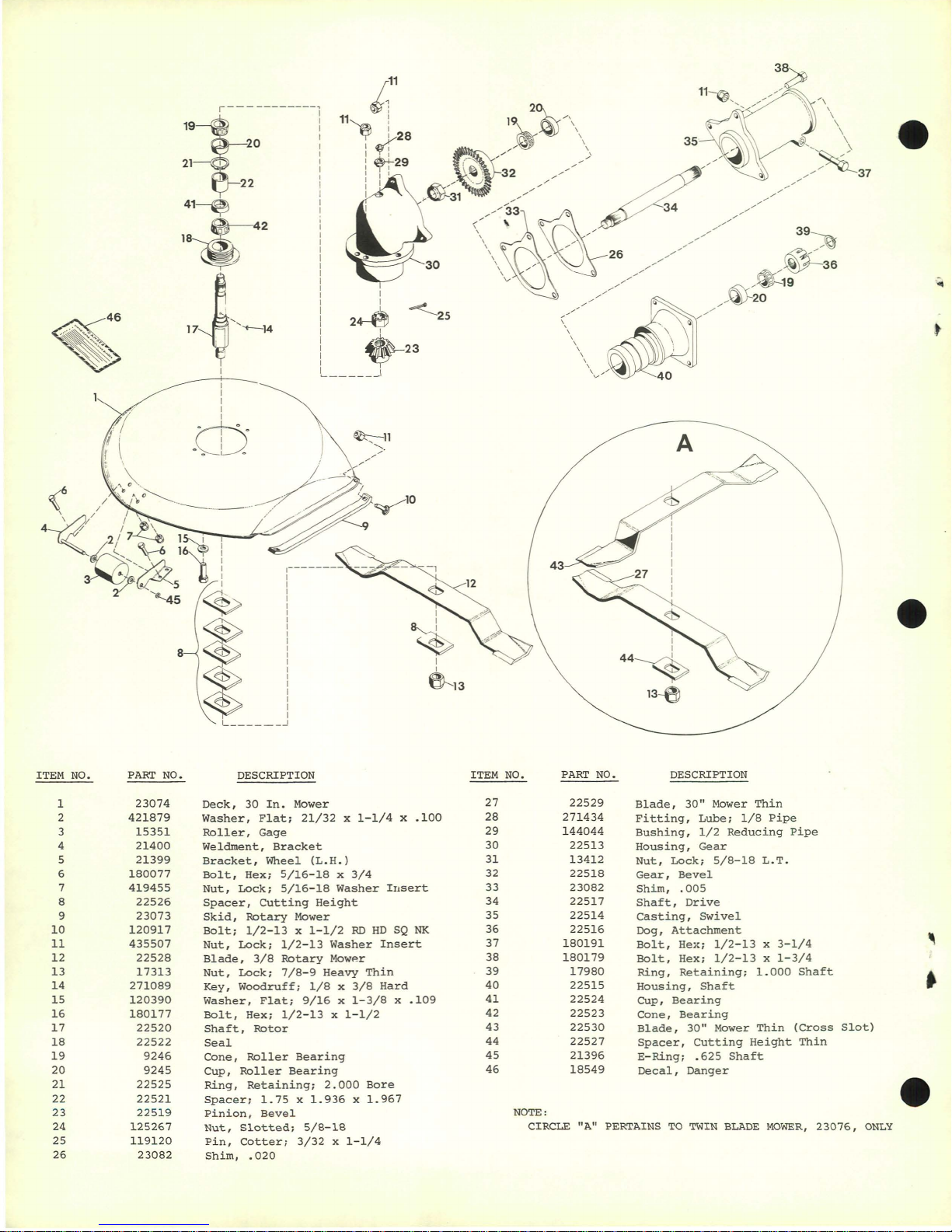
ITEM NO.
PART
NO.
DESCRIPTION
ITEM NO.
PART
NO. DESCRIPTION
NOTE:
CIRCLE "A" PERTAINS
TO
TWIN
BLADE
MOWER,
23076,
ONLY
1
2
3
4
5
6
7
8
9
10
11
12
13
14
15
16
17
18
19
20
21
22
23
24
25
26
23074
421879
15351
21400
21399
180077
419455
22526
23073
120917
435507
22528
17313
271089
120390
180177
22520
22522
9246
9245
22525
22521
22519
125267
119120
23082
Deck,
30
In.
Mower
Washer,
Flat;
21/32x1-1/4x.100
Roller,
Gage
Weldrnent,
Bracket
Bracket,
Wheel
(L.H.)
Bolt,
Hex;
5/16-18
x
3/4
Nut,
Lock;
5/16-18
Washer
Insert
Spacer,
Cutting
Height
Skid,
Rotary
Mower
Bolt;
1/2-13x1-1/2
RDHDSQ
NK
Nut,
Lock;
1/2-13
Washer
Insert
Blade,
3/8
Rotary
Mow~r
Nut,
Lock;
7/8-9
Heavy
Thin
Key,
Woodruff;
1/8x3/8
Hard
Washer,
Flat;
9/16x1-3/8x.109
Bolt,
Hex;
1/2-13x1-1/2
Shaft,
Rotor
Seal
Cone,
Roller
Bearing
Cup,
Roller
Bearing
Ring,
Retaining;
2.000
Bore
Spacer;
1.75x1.936x1.967
Pinion,
Bevel
Nut,
Slotted;
5/8-18
Pin,
Cotter;
3/32x1-1/4
Shim,
.020
27
28
29
30
31
32
33
34
35
36
37
38
39
40
41
42
43
44
45
46
22529
271434
144044
22513
13412
22518
23082
22517
22514
22516
180191
180179
17980
22515
22524
22523
22530
22527
21396
18549
Blade,
30"
Mower
Thin
Fitting,
Lube;
1/8
Pipe
Bushing,
1/2
Reducing
Pipe
Housing,
Gear
Nut,
Lock;
5/8-18
L.T.
Gear,
Bevel
Shim,
.005
Shaft,
Drive
Casting,
Swivel
Dog,
Attachment
Bolt,
He~;
1/2-13x3-1/4
Bolt,
Hex;
1/2-13x1-3/4
Ring,
Retaining;
1.000
Shaft
Housing,
Shaft
Cup,
Bearing
Cone,
Bearing
Blade,
30"
Mower
Thin
(Cross
Slot)
Spacer,
Cutting
Height
Thin
E-Ring;
.625
Shaft
Decal,
Danger
•
BrentChalmers.com
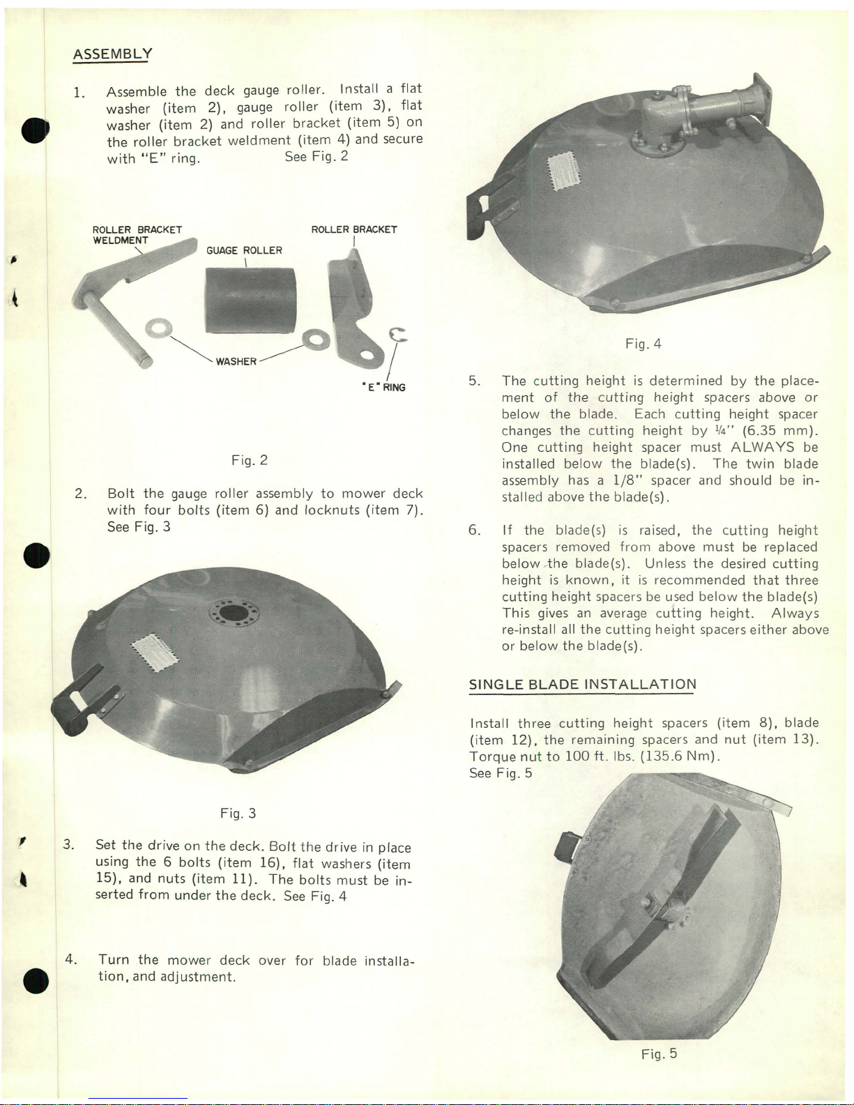
ASSEMBLY
4.
Turn
the
mower
deck
over
for
blade
installa-
e
tion,
and
adjustment.
Fig.4
If
the
blade(s)
is
raised,
the
cutting
height
spacers removed
from
above
must
be
replaced
below
Ahe blade(s). Unless
the
desired
cutting
heightisknown,
itisrecommended
that
three
cutting
height
spacersbeused
below
the
blade(s)
This
gives
an
average
cutting
height.
Always
re-install all
the
cutting
height
spacers
either
above
or
below
the
blade(s).
The
cutting
heightisdetermined
by
the
place-
ment
of
the
cutting
height
spacers above
or
below
the
blade. Each
cutting
height
spacer
changes
the
cutting
height
by
1/
4
"
(6.35
mm).
One
cutting
height
spacer
must
ALWAYS
be
installed
below
the
blade(s).
The
twin
blade
assembly has a
1/8"
spacer and
should
be
in-
stalled above
the
blade(s).
Install
three
cutting
height
spacers
(item
8),
blade
(item
12),
the
remaining
spacers and
nut
(item
13).
Torque
nutto100
ft.
Ibs.
(135.6
Nm).
See
Fig. 5
SINGLE
BLADE
INSTALLATION
5.
6.
ROLLER BRACKET
I
Fig.2
Fig.3
GUAGE
ROLLER
\
~WASHER~
Bolt
the
gauge
roller
assembly
to
mower
deck
with
four
bolts
(item6)and
locknuts
(item
7).
See
Fig. 3
2.
1.
Assemble
the
deck
gauge
roller.
Install a
flat
washer
(item
2).
gauge
roller
(item
3).
flat
washer
(item
2) and
roller
bracket
(item5)on
the
roller
bracket
weldment
(item
4) and secure
with
OlE"
ring.
See
Fig.
2
f 3. Set
the
driveonthe
deck.
Bolt
the
drive
in place
using
the6bolts
(item
16),
flat
washers
(item
,
15),
and
nuts
(item
11).
The
bolts
must
be
in-
serted
from
under
the
deck.
See
Fig. 4
Fig.5
BrentChalmers.com
 Loading...