


~GRAVELV
A DIVISIO:'\ OF CLARKE-GRAVELY CORI'ORATIO:'\
To continue .ts program of qualltv and deSign Impro ement. the
manufacturer reserves the right to change specifications. design
or prices without nOtIce and without Incurring obligatiOn
OWNERS
MANUAL
34" ROTARY MOWER
. MODEL NUMBER 15459E1
~'.
"
..
.
.
l .GRAVELY.
]
408 LAWN TRACTOR WITH 34" ROTARY MOWER
GENERAL
1. The 34" mower is a center mounted unit
custom designed and built expressly for the
408 Lawn Tractor. The mower is recom-
mended for homeowners lawns and comes
from the factory fully assembled.
2. The Owners Manual includes attaching to the
tractor, safety, operation and maintenance
1
instructions. Use the illustrated parts list for
reference to individual part numbers. Contact
the Gravely Dealer for further information.
3. Height: 14"
Weight: 105 lbs.
Length: 27 1/2"
Width: 44"
Cutting Width: 34"
Deck: One piece stamped steel.
Drive: Right angl. bevel gears, ball bearings,
aluminum housing, self-adjusting spring
tensioned V-belt.
Blades: 2 steel, hi-strength, hi-lift
17" length, .204" thick
Features: Cutting height adjusts from opera-
tors position.
Purpose: Homeowners lawn care.
Tractor: 408 Lawn Tractor
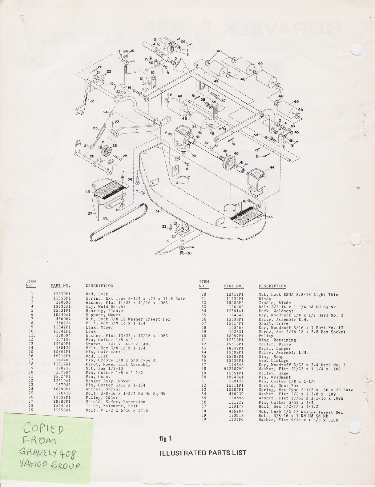
ITEM
NO.
1 15339P1
2
3 120393
4 15332A1
5
6
7
8
9
10. 15341P1
11. 120394
12
13 15340P1
14
15 15691P1
16
17
18
19
20
21
22 15319A1
23
24
25 126416
26
27
28
29 15355A1
PART NO.
15353P1
15331P1
19946A1
456004
180124
15342P1
137185
180124
19316P1
142485
ll317A1
120238
137204
15324P1
187988
18295P1
15352P1
19987P1
15344A1
DESCRIPTION
Rod, Lock
Spring, Ext Type 2-1/4 x .75 x 11.8 Rate
Washer, Flat 11/32 x 11/16 x .065
Adj. Weld Height
Bearing, Flange
Support, Mower
Nut, Lock 3/8-16 Washer Insert Hex
Bolt, Hex 3/8-16 x 1-1/4
Link, Mower
Link
Washer, Flat 13/32 x 13/16 x .065
Pin, Cotter 1/8 x 1
Spacer, .447 x .687 x .400
Bolt, Hex 3/8-16 x 1-1/4
Pin, Hair Cotter
Rod, Lift
Pin, Groove 1/8 x 5/8 Type A
Pivot, Mower Lift Assembly
Nut, Jam 1/2-13
Pin, Cotter 1/8 x 1-1/2
Pin, Conn.
Hanger Assy. Mower
Pin, Cotter 3/16 x 1-1/4
Anchor, Spring
Bolt, 3/8-16 x 1-3/4 Rd Hd Sq Nk
Pulley, Idler
Shield, Safety Estension
Idler, We1dment, Belt
Belt, V 1/2 x 5/16 x 37.6
ITEM
NO.
30
31
32
33
34
35
36
37
38
39
40
41
42
43
44
45
46
47
48
49
50
51
52
53
54
55
56
57
58
59
60
PART NO.
13412P1
ll234P1
10986P2
126402
15301A1
124543
15308P1
15314P1
103462
102581
18087P1
15318P1
15316P1
18549P1
15309P1
15388P1
15337P1
124548
94218790
15351P1
19948A1
120123
153llP1
15255P1
446239
120396
121222
180177
435507
120915
120390
DESCRIPTION
Nut, Lock ESNA 5/8-18 Light Thin
Blade
Cradle, "Blade
Bolt 3/8-16 x 1-1/4 Rd Hd Sq Nk
Deck, We1dment
Key, Woodruff 1/8 x 1/2 Hard No. 3
Drive, Assembly R.H.
Shaft, Drive
Key, Woodruff 3/16 x 1 Soft No. 13
Screw, Set 5/16-18 x 3/8 Hex Socket
Pulley
Ring, Retaining
Collar, Drive
Decal, Danger
Drive, Assembly L.H.
Ring, Snap
Arm, Linkage
Key, Woodruff 5/32 x 3/4 Hard No. 8
Washer, Flat 21/32 x 1-1/4 x .100
Roller, Gage
Pin, We1dment
Pin, Cotter 1/8 x 1-1/4
Shield, Gear Box
Spring, Ext Type 5-1/2 x .50 x 20 Rate
Washer, Flat 5/8 x 1-3/8 x .109
Washer, Flat 17/32 x 1-1/16 x .095
Pin, Cotter 3/32 x 3/4
Bolt, Hex 1/2-13 x 1-1/2
Nut, Lock 1/2-13 Washer Insert Hex
Bolt, 3/8-16 x 1 Rd Hd Sq Nk
Washer, Flat 9/16 x 1-3/8 x .109
~OPlfP
12-ftOfV\
GRAVf:L"/108'
YA~ooGROvP
-
fig1
ILLUSTRATED PARTS LIST

COPlfP
~"'OM
ATTACHING
1.
Slide the lift pivot on the lift rod with the
groove pin towards the bend in the lift rod,
fig 1, Items 16, 17, and 18.
2.
Run (me of the jam nuts 3/4 of the way on
the threaded portion of the lift rod. Keeping
it in position, jam the other nut against it,
fig 1, Items 16 and 19. .
3. Lower the attachment lift on the tractor all
the way down.
4.
Work from the right side of the tractor. Turn
the lift rod upside down (bent part up), and
put the lift pivot in the second hole from the
end of the tractor lift. Put it in from the right
side.
5. Rotate the lift rod to the right-side-up posi-
tion (bent part down) and raise the tractor
lift all the way up.
6. Slide the mower under the tractor, center the
hanger assembly and move it as forward as
possible.
7. Put the PTO in the IN position.
8. Slip the belt on the PTO pulley.
G-~AVf:L'1,+08
SAFETY
1.
READ THE TRACTOR OWNERS MANUAL.
Be familiar with all controls and follow safety
precautions outlined in the manual.
DO NOT ALLOW PASSENGERS to accom-
2.
pany the operator at any time.
3.
DO NOT ALLOW CHILDREN to operate the
equipment, nor allow adults to operate it
without proper instructions.
4.
INSPECT THE WORK AREA for rocks, glass,
metal, bones, and any other foreign objects.
Stay alert for holes and other hidden hazards.
5.
USE EXTREME CAUTION when operating
on slopes.
6. REDUCE SPEED on all side slopes and shart
turns.
7. DO NOT OPERATE equipment except from
operator position at the handles of the tractor.
8. KEEP SAFETY devices and shields in place
at all times.
9. DISENGAGE POWER to attachment and
stop the engine prior to making any adjust-
ment or clearing the unit.
,/1%\00 GWVp
9. Slide the mower as rearward as possible.
10. Lower the lift rod and connect it to the
hanger assembly with a flatwasher and a
hair pin cotter as in fig 1, Items 15 and 55.
10. DO NOT WEAR LOOSE fitting clothing.
11. KEEP HANDS, feet, hair, clothing, etc., away
from moving parts.
12. KEEP BYSTANDERS and pets removed from
11. Open the tractor attachment latches.
12. With the tractor lift lever, lift the mower and
guide the hanger into the attachment latches.
13. Close the attachment latches, lock them with
hair pin cotters and lower the mower.
"
the work area.
13. DIRECT DISCHARGE so as not to endanger
life or property; such as people, pets, struc-
tures, cars, etc.
OPERATION
14. Hook the spring anchors to the spring and
connect this assembly between the idler shaft
and the hanger assembly, fig 1, Items 22, 24,
28 and 53.
1. Refer to the tractor Owners Manual for
safety and operating instr~ctions to engage
and disengage the PTO (power take-off).
15. Set the flat side of the belt on the idler
pulley, fig 1, Item 26. The belt is now in the
tensioned running position. Put the PTO in
the OUT position.
2.
After the PTO is engaged run the engine at
full speed. In thick, lush growth reduce
ground speed (not engine speed) to allow che
mower enough time to cut and discharge.

r
~OPlfJ)
1=--f\OfV1
ADJUSTMENTS
GRAVtLY't0g
YAHOO GR.OvP
1. Cutting Height: The cutting height is con-
trolled by the lever on the right side of the
mower, fig 1, Items 1 and 4. It is most
easily adjusted when the mower is in the
raised (transport) position: adjusting the lever
forward for a low cut, rearward for a high
cut. The total range is 2 1/4 inches.
2. Leveling: If the mower appears to cut closer
to the ground on one side than the other,
adjust the mower support where it connects
to the roller assembly, fig 1, Items 6, 50,55,
57 and 58. To adjust, move the forked end of
the support away from the roller shaft to
make the right side cut higher. Move the
forked end of the support closer to the roller
shaft to make the right side cut lower.
3.
Belt Alignment: If the belt appears to be
wearing more on one side than the other, it is
possible that the mower pulley is not aligned
with the PTO pulley. To adjust, loosen the set
screw in the hub of the mower pulley, fig 1,
Items 37, 38, 39 and 40. Move the pulley in
the direction of the worn side of the belt
until the pulleys align. Raise the hood and
view from above. Retighten the set screw.
4.
Blade Timing: Correct timing is as follows:
one biade is in the cradle front to rear while
at the same time the other blade is in the
cradle side to side (900 out of phase), fig 1,
Items 31 and 32. To adjust, remove either one
of the collar retaining rings, fig 1, Items 41
and 42. Slide the collar towards the middle of
the shaft. Rotate the blades for correct
timing. Slide the collar back on the gear box
shaft and lock it in position with the retaining
ring.
5.
Lift Rod: If the mower does not come up
high enough when the lift lever is in the top
notch, move the jam nuts closer to the bend
in the lift rod. This adjustment should bring
the mower up closer to the tractor and still
allow the mower to "float" when all the way
down.
between the blades and the side of the
mower deck.
C. If the cradles are removed, be sure to
reinstall them with the woodruff keys,
fig 1, Item 35.
7. Blade Installation:
A. Set the blades in the cradles as in fig 1,
Items 31 and 32. The lift portion of the
blades points towards the mower deck.
B. Put on the washers and torque the nuts
to 25 ft. lbs., fig 1, Items 30 and 54.
Similar tightness can be reached with
any 8" length handle wrench when used
by an average man. A block of wood or
something similar can be used to keep
the blades from turning. Place the wedge
between the blade and the side of the
mower deck.
C. Check to be sure that the blades are
properly timed.
8. Belt Replacement:
A. Remove the mower from the tractor.
B. Remove the retaining rings from the
drive shaft, fig 1, Item 41.
C. Slide the collars toward the pulley, fig 1,
Item 42.
D. Remove the shaft and the old belt from
the shaft.
E. Set the new belt on the pulley and
reinstall the shaft. Note: Be sure that the
blades are properly timed when reas-
sembling the drive.
REMOVAL FROM TRACTOR
1. Lower the mower and disconnect the spring.
2. Raise the mower and open the attachment
latches.
3. Lower the mower and disconnect the lift rod
from the mower hanger and the tractor lift
lever.
4. Move the mower as forward as possible.
6. Blade Removal:
A. Remove the mower from the tractor and
turn the mower upside down.
B. Remove the nuts, washers and blades,
fig 1, Items 30, 31 and 54. It is not
ntcessary to remove the blade cradles,
fig 1, Item 35. A block of wood or
something similar can be used to keep
the blades from turning. Place the wedge
5. Put the PTO in the IN position and remove
the belt from the PTO pulley.
6. Slide the mower from under the tractor.
7. Reconnect the lift rod to the mower for
storage.
"

TROUBLE SHOOTING
ROUTINE MAINTENANCE
1. Blade timing is set at the factory and (with
normal use) cannot go out of time. The
obvious symptom of improper blade timing
is the sound of the blades hitting together.
2. Causes of improper blade timing:
A. The blades were not timed properly
..
3. Corrections for Items A, 'B and C:
when a new belt was installed.
B. A blade hit something hard enough to
shear its woodruff key allowing the
cradle to turn on the shaft, fig 1, Item
35. The key keeps the blade cradle from
turning on the shaft.
C. The same impact condition as "B" ex-
cept that the key did not shear but the
drive collar has turned (slipped) on the
shaft, fig 1, Item 42. This condition is
rare as the key should shear (to protect
the driveline) before the collar will slip.
A. Retime the blades; see ADJUSTMENTS.
B. Remove the blade and cradle and install
a new woodruff key. Check blade timing;
see ADJUSTMENTS.
C. Replace the drive collar with a new one;
check the drive shaft and gear box shaft
for damage. Retime the blades; see
ADJUSTMENTS.
1. Keep the mower blades sharp and balanced.
2. Keep the mower clear of cuttings and debris.
3. Periodically inspect the drive housings for
leakage of lubricant, fig 1, Items 36 and 44.
If the drive housings show signs of leakage,
contact the Gravely Dealer. Do not open the
drive housing as this voids warranty.
STORAG E
1. Clean the mower of all cuttings and debris.
2. Perform all routine maintenance.
3. Apply a light coat of oil to preserve the finish
and appearance.
FORM NUMBER: 20812L2
EFFECTIVE DATE: 6-15-74
PRINTED IN USA
COf~EP
~f\OfV\
G~AVf:Lvl ,+08
,/A800 GRfJ0P
-
..
I ----
--:;--~--
 Loading...