

Gravely 12621209-12 User Manual

PECOPECO
PECOPECOPECO
P
PPPP
GRAVELY 200 SERIES MOWER
GRASS COLLECTION
SYSTEM
DESIGNED FOR:
MODEL 12621209 - 12
OPERATOR’S MANUAL
ASSEMBLY OPERATION MAINTENANCE
MANUAL PART#: Q0316 $4.00 REV: 1
PECO GRASS COLLECTION SYSTEM
TABLE OF CONTENTS
SECTION PAGE
Safety ------------------------------2
Safety Alert Symbols----------------------3
Warranty -----------------------------4
I INTRODUCTION AND DESCRIPTION - - ------------5
1-1 Introduction - ------------------------5
1-2 Description - ------------------------5
II PREPARATION FOR USE ----------------------5
2-1 Preparation Of Mower ------------------5
2-2 Attaching The Top Main Frame Assembly ------5
2-3 Attaching The Lift Handle To The Aluminum
Grass Container- ------------------------6
2-4 Attaching The Aluminum Grass Container To
The Unit ------------------------------6
2-5 Aluminum Grass Container Inlet Attachment ----6
2-6 Adjusting The Dump Mechanism -----------6
2-7 Attaching The Outer Motor Mount Tube To
The Left & Right Lower Main Frame Legs - - ------6
2-8 Motor Mount Arm Installation - - ------------9
2-9 Engine/Blower/Blade Assembly Installation ----9
Safety
SECTION PAGE
2-10 Attaching The Boot To The Mower Deck ------9
2-11 Adjusting The Length Of Hose ------------9
2-12 Attaching The Upper Hose- - - ------------10
2-13 Attaching The Lower Hose To The Blower
Cone - - ------------------------------10
2-14 Attaching The Lower Hose To The Boot ------10
2-15 Front Weight Assembly-----------------10
III OPERATING INSTRUCTIONS - ------------------11
3-1 General Safety -----------------------11
3-2 Operation & Tips On Mowing- - ------------11
3-3 Unloading The Collection System -----------11
IV MAINTENANCE ----------------------------11
4-1 Maintenance Checklist ------------------11
V PARTS AND SERVICE ------------------------12
5-1 Parts And Service Information - ------------12
Torque Specifications - - - ------------------13
Notes- - ------------------------ 14-15
1.
Read the operator’s manual carefully and familiarize yourself with the proper use of your attachment. Do not allow
anyone who is not acquainted with the Safety Instructions to use your attachment.
2.
Know the controls and how to stop quickly. READ THE OPERATOR’S MANUAL!
3.
Do not allow children to operate the vehicle. Do not allow adults to operate it without proper instruction.
4.
Be especially watchful of children and pets darting into the area while operating.
5.
Keep your eyes and mind on your unit while mowing or operating your attachment. Don’t let others distract you.
6.
Do not attempt to operate your unit or mower when not in the driver’s seat.
7.
Always stop unit when emptying the container.
8.
Stop unit, shut off deck attachment, set parking brake, shut off mower engine and remove spark plug wire before
removing clogs, removing or replacing hose, boot, blower cone, or performing any maintenance.
9.
Mow up and down the face of slopes (not steeper than 10 degrees); never across the face of the slope.
10.
It is recommended that the container be kept only half full when negotiating any slopes. Start mowing on slopes
when the container is empty.
11.
Inspect your lawn and remove any foreign objects before mowing. Never deliberately run the mower across any
foreign object.
12.
Wear ear protection if the noise level is offensive.
13.
Wear eye protection to prevent debris from damaging your eyes.
2

SAFETY
WARNING!
vacuum collector adapter are fastened securely in place.
WARNING!
blades and the blower impeller have stopped rotating.
WARNING!
STOPPING THE MOWER’S ENGINE AND WAITING FOR ALL MOVING PARTS TO COME TO A
COMPLETE STOP.
WARNING!
across the face. attempt to mow excessively steep slopes, and use caution when turning on any slope.
NEVER
Do not work around the mower deck boot or the blower area until you are certain that the mower
To avoid serious injury, perform maintenance on the vacuum collector;
Set the parking brake. Always remove the ignition key before beginning maintenance.
For your own personal safety, mow and the face of slopes and
NEVER
operate the unit unless the discharge guard and either the deflector assembly or the
ONLY AFTER
ALWAYS UP DOWN NEVER
Safety Alert Symbol
“ATTENTION! BECOME
!
This Safety Alert Symbol means:
ALERT! YOUR SAFETY IS INVOLVED!”
This symbol is used to call attention to safety precautions that
Should be followed by the operator to avoid accidents. When
you see this symbol, carefully read the message that follows
and heed its advice. Failure to comply with safety precautions
could result in death or serious bodily injury.
Safety Signs
The signal words and are used on the equipment safety signs. These words are
intended to alert the viewer to the existence and the degree of hazard seriousness.
!
!
Black letters on ORANGE
!
Black letters on YELLOW
DANGER, WARNING, CAUTION
This signal word indicates a potentially hazardous situation which, if not
DANGER
White letters on RED
WARNING
CAUTION
avoided, will result in death or serious injury.
This signal word indicates a potentially hazardous situation which, if not
avoided, could result in death or serious injury.
It may also be used to alert against unsafe practices.
This signal word indicates a potentially hazardous situation exist which, if
not avoided, will result in minor or moderate injury.
It may also be used to alert against unsafe practices.
3

PECO LIMITED WARRANTY FOR NEW PRODUCTS
A. WHAT IS WARRANTED?
PECO extends the following warranties to the original purchaser of each new PECO consumer product subject
to the following limitations:
1. PRODUCT WARRANTY:
delivered to the purchaser will be repaired or replaced, as PECO elects, without charge for parts or labor, if the
defect appears within 12 months from the date of delivery of the product to the original purchaser.
DEFECTIVE PARTS MUST BE RETURNED TO PECO FOR INSPECTION TO DETERMINE
VALIDITY OF WARRANTY CLAIMS.
2. PARTS REPLACED DURING WARRANTY:
warranty and is defective in material or workmanship as delivered to the purchaser will be repaired or replaced,
as PECO elects, without charge if the defect appears within 90 days from the date of installation of such part or
before the expiration of the original warranty period, whichever is later.
B. SECURING WARRANTY ADJUSTMENTS.
Call PECO for Return Authorization. Damaged or broken parts, other than engines or batteries, must be
returned to PECO Inc., 100 Airport Road, Arden, NC 28704 before any warranty adjustment can be authorized.
At the time of requesting warranty adjustment, the purchaser must present evidence for date of delivery of the
product. The purchaser shall pay any charge for the product to and from Arden, NC.
C. ITEMS NOT COVERED BY PECO WARRANTY.
Engines and batteries attached to PECO products are covered under a separate warranty by the respective
manufacturer.
D. UNAPPROVED ALTERATION OR MODIFICATION.
All obligations of PECO Inc., under this warranty, shall be terminated if products are altered or modified in ways
not approved by PECO Inc..
E. ACCIDENTS AND NORMAL MAINTENANCE.
The warranty covers only defective material and workmanship. It does not cover depreciation or damage
caused by normal wear, accident, improper use or abuse of products. The cost of normal maintenance and
normal replacement of service items such as belts, cutting blades, hoses, etc., which are not defective shall be
paid for by the purchaser.
F. NO REPRESENTATIONS ADDITIONAL WARRANTIES, DISCLAIMER.
Neither PECO Inc. nor any company affiliated with it makes any warranties, representations or promises as to
the quality of performance of its products other than those set forth herein. Except as described above, PECO
Inc. makes no other warranties
WARRANTIES OF FITNESS AND MERCHANTABILITY.
G. ANY MACHINE USED FOR RENTAL PURPOSES ARE GUARANTEED FOR 45 DAYS FROM DATE
OF ORIGINAL SALE ONLY.
H. REMEDIED EXCLUSIVE.
The only remedies the purchaser has in connection with the breach or performance of any warranty on PECO
Inc. consumer products are set forth above. In no event will PECO be liable for special incidental or
consequential damages.
1. NO SERVICE CENTER WARRANTY.
The selling Service Center makes no warranty on his own on any item warranted by PECO Inc. unless he
delivers to purchaser a separate written warranty certificate specifically warranting the item. The dealer has no
authority to make any representation or promise on behalf of PECO or to modify the terms of this warranty in
any way.
Any part of any consumer product, which is defective in material or workmanship as
ALL
Freight and mailing will be borne by the customer.
Any new PECO part which is furnished in performance of this
AND SPECIFICALLY DISCLAIMS ANY AND ALL IMPLIED
4
SECTION I
INTRODUCTION AND DESCRIPTION
1-1 Introduction
We are pleased to have you as a PECO customer. Your
collection system has been designed to give you a low
maintenance, simple, and effective way to collect the
grass clippings from your mower. This manual is
provided to give you the necessary instructions to
properly mount and operate the collection system on
your mower. Please read this manual thoroughly.
Understand what each control is for and how to use it.
Observe all safety decal precautions on the machine and
noted throughout the manual.
all references made to right, left, front, rear, top or
Note:
bottom are as viewed from the normal operator’s
position on the mower.
1-2 Description
The collection system is designed for turf maintenance
where there is a need to collect the grass clippings as
the mower cuts the turf. It is also good for picking up
leaves and twigs in pre-season and post-season cleanup.
The engine/blower/blade assembly, is mounted on the
right side of the unit. The blower draws grass clippings
from the discharge area of the cutter deck up to the
aluminum container mounted over the rear portion of the
frame. The operator can engage the
engine/blower/blade assembly by starting the engine.
Once the container is full of clippings, the operator can
easily push and raise the lift handle, releasing the
container’s rear door and the container will pivot towards
the ground.
Section II
INSTALLATION FOR USE
2-1 Preparation Of Mower
Carefully dismantle wooden shipping crate from around
the components. Cut retaining straps and separate the
parts. The collection system will have various parts
located inside. Remove and sort all parts for easy
identification.
P#(K1198) and (2) 3/8”-16 flange nuts P#(K1215). Use
the existing bolt removed from the mower to fasten the
front side of the leg. Repeat this step to fasten the right
main frame leg assembly P#(A0514). See Figure 1 for
details.
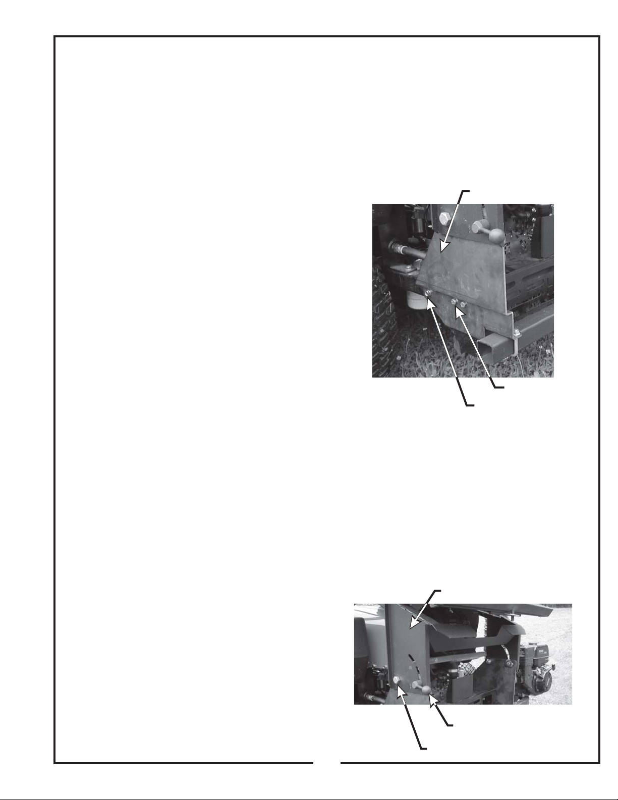
Figure 1 Left Lower Main
Frame Leg.
Left Lower Main Frame Leg
3/8” x 3” HHCS
Existing Bolt
2-2 Attaching The Top Main Frame
Assembly
Place the top main frame assembly P#(A0944) (Figure 2)
onto the main frame legs and fasten each side by using
(1) 3/4”-10 x 1-1/2” HHCS P#(K0364), (1) 3/4”-10 nyloc
nut P#(K1433), (1) ½”-13 x 1” HHCS P#(K1231), and (1)
pivot frame handle P#(A1001). The handles are used to
pivot the frame to the rear for mower engine access. Be
sure that the handles are tight and the frame is in the
upright position before each use!
Figure 2 Top Main Frame Assy.
Top Main Frame Assembly
NOTE:
the exploded drawings on pages 7 and 8.
Remove the (3) bolts (Figure 1) from each side of the
rear of the mower. Keep the bolt, from each side, that
threads through the mower’s rear frame. Place the left
lower main frame leg P#(A0511) onto the rear of the
mower and fasten by using (2) 3/8”-16 x 3” HHCS
before each step of assembly it will help to study
Pivot Frame Handle
3/4” x 1-1/2” HHCS
5
 Loading...