

Gravely 11362 User Manual

OPERATOR'S
MANUAL
NAME: 40" COMMERCIAL MOWER
40" COMMERCIAL MOWER ATTACHED TO C12 TRACTOR WITH DUAL WHEELS
GENERAL
1. The 40" Commercial Mower is a front mount unit
designed and built to give many years of excellent
service. The mower is recommended for rough
mowing conditions; has all gear drive from engine to
mower, heavy-duty steel deck, rugged skids and
casters, and 2 adjustable blades. The mower
attaches to both 2 and 4 wheel tractors (see
paragraph 3).
2. The Owners Manual includes the parts list, setting
up the mower, safety, operation, and maintenance
instructions. Use the parts list for reference to
individual part numbers. If further information is
necessary contact the local Gravely dealer.
3. Height: 15-1/2" Weight: 182 lbs.
Length: 34-3/4" Width: 42"
Cutting Width: 40"
Deck: Reinforced, welded steel.
Drive: Right angle bevel gear, tapered roller
bearings, cast iron housing, 2 self
adjusting spring tensioned V-belts.
PART NUMBER(S): 11362 - 40" Commercial Drive
11368 - 40" Commercial Deck
Blades: 2 steel, hi-strength, hi-lift,
20-1/2" length, 3/16" thick
Features: Adjustable casters, adjustable swivel
action.
Purpose: Heavy mowing conditions.
Recommended for the following tractors:
7.6 - C10A - C12
424 - 430 - 432
810 - 812 - 814 - 816S
Required attaching kits:
7.6 - C10A - C12: None
424 - 430 - 432:
15840E1 Front Drive Kit
11601E1 Front Adapter Kit
810-812-814-816S:
19075E1 Front Drive Kit
11601E1 Front Adapter Kit
Recommended optional equipment for special
applications:
7.6 - C10A - C12: None
Riding Tractors:
20181E1 Wheel Brake Kit, 800 Series
11924E1 Front Wheel Weights
Recommend option for riding tractors without
hydraulics:
11271E1 Lift Assist Kit
1

fig 1
ITEM N0. PART N0. DESCRIPTION
1 11369A1 Deck Weldment
2 180126 Bolt, Hex 3/8-16 x 1-1/2
3 9231P1 Idler
4 11379A1 Arm, Idler Pivot Weldment
5 11382A1 Idler, Pivot Arm
6 456004 Nut, Lock 3/8-16 Washer Insert
7 11263P1 Spring
8 9200A1 Housing, Spindle Bearing Weldment
9 9246P1 Bearing, Cones
10 9245P1 Bearing, Race
11 9206P1 Seal, Oil
12 9204P1 Ring, Seal
13 9207P1 Pulley, Rotor
14 131001 Washer, Flat 31/32 x 2-1/4 x .165
15 17313P1 Nut, Lock Esna 7/8-9 Heavy Thin
16 9203P1 Shaft, Rotor
17 9213P1 Key, Square 1/4 x 1
18 9205P1 Shield, Dust
19 9211P1 Collar, Blade Spacer 3/4"
20 9210P1 Collar, Blade Spacer 1/2"
21 9209P1 Collar, Blade Spacer 1/4"
22 9212P1 Blade, Mower
23 102581 Screw, Set 5/16-18 x 3/8 Hex Socket
24 94110270 Fitting, Lube 1/4-28
Complete 40" Rotary Mower Spindles R.H. #10398A1 and L.H.
#10399A1 Include Item Numbers 8 through 21 and Numbers 23 and 24
25 120915 Bolt, 3/8-16 x 1 Rd. Hd. Sq. Nk.
26 456004 Nut, Lock 3/8-16 Washer Insert
27 11384P1 Cover, Belt
28 94286380 Bolt, 3/8-16 x 5/8 Hex Hd.
29 120382 Washer, Lock 3/8 Sp.
30 120394 Washer, Flat 13/32 x 13/16 x .065
31 9240P1 Belt, Drive
32 9223P2 Skid
33 181596 Bolt, 5/16-24 x 7/8 Hex Hd.
34 120214 Washer, Lock 5/16 Sp.
35 120393 Washer, Flat 11/32 x 13/16 x .065
36 11376A1 Support, Deck Weldment
37 18549P1 Decal, Danger
38 11375P1 Bearing, Bronze
39 94110270 Fitting, Lube 1/4-28
40 180122 Bolt, Hex 3/8-16 x 1
41 120897 Bolt, 1/2-13 x 3 Rd. Hd. Sq. Nk
42 120384 Washer, Lock 1/2 Spring
43 120378 Nut, Hex 1/2-13
NS 9251A1 Guard, Weldment
45 137204 Pin, Cotter 1/8 x 1-1/2
46 131017 Washer, Flat
47 11385A1 Caster Fork Weldment
48 113871`1 Bushing
49 11386P1 Wheel, Caster
50 180193 Bolt, Hex 1/2-13 x 3-3/4
51 435507 Nut, Lock 1/2-13 Washer Insert
ILLUSTRATED PARTS LIST Continued on Page 4
2
ASSEMBLY
g
g
1. Unpack the drive and deck.
2. Remove the belt covers, fig 1, Items 27.
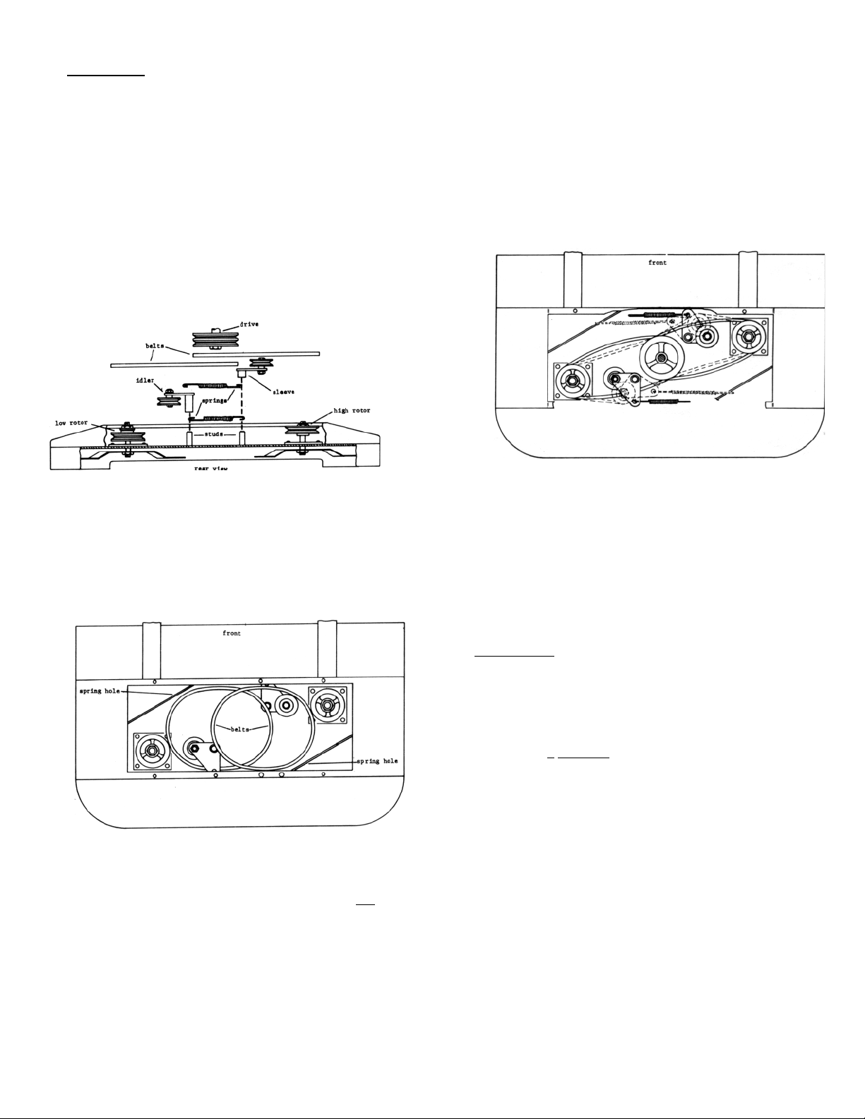
3. Mount the idlers on the studs as in fig 2. Note the
different sleeve lengths of the idlers. The short
sleeve goes next to the high rotor and the tall
sleeve goes next to the low rotor. Set the idlers
on the studs with the extended sleeves down.
Work from the rear of the mower.
7. Bolt the drive to the deck. The 2 carriage bolts
are inserted from under the deck, fig 1, Items 41,
42 & 43. Be sure that the heads seat properly in
the deck. The 3 hex bolts fasten from the top, fig
1, Items 29 & 40. Start all bolts and nuts before
tightening.
fi
2
4. Set the belts as in fig 3; low belt first. This belt
positioning is important for ease of assembly.
3
fi
5. Hook the springs to the idler assembly from
underneath as in figs 2 & 4, solid lines.
6. Set the drive in position on the deck; do not
bolt
it down. Slip the belts on the drive pulley and
then on the rotor pulleys. Let the idlers float at
this time; solid lines, fig 4.
fig 4
8. Working from the sides, grip the springs with a spring
puller or clamp-lock pliers or equivalent. Extend the
spring hook up, over, and through the spring hole.
The belts are now in tensioned running position;
dotted lines fig 4.
9. Replace the belt covers.
10. Install the bushings in the caster wheels and
bolt the wheels in the caster forks.
LUBRICATION
1. Grease the spindle bearing weldment housing through
the grease fitting, with general purpose grease fig 1,
Item 8 & 24. Add grease until it comes out the vent
hole; opposite side of the grease fitting. Re-grease
every 8
HOURS of operation or more often when
operating in severe dust or sand.
2. Grease the bronze bearing and caster wheels through
the grease fittings with general purpose grease fig 1,
Items 38 & 49. Add grease until it comes out the
bearings. Re-grease periodically, especially when
operating in severe dust or sand.
3
 Loading...