

Graupner and KG MC-16 User Manual
not correspond to the product (e.g. a transmitter
update fi le instead of a receiver update fi le), the
"Product code error" popup window will appear
and the update process will not star
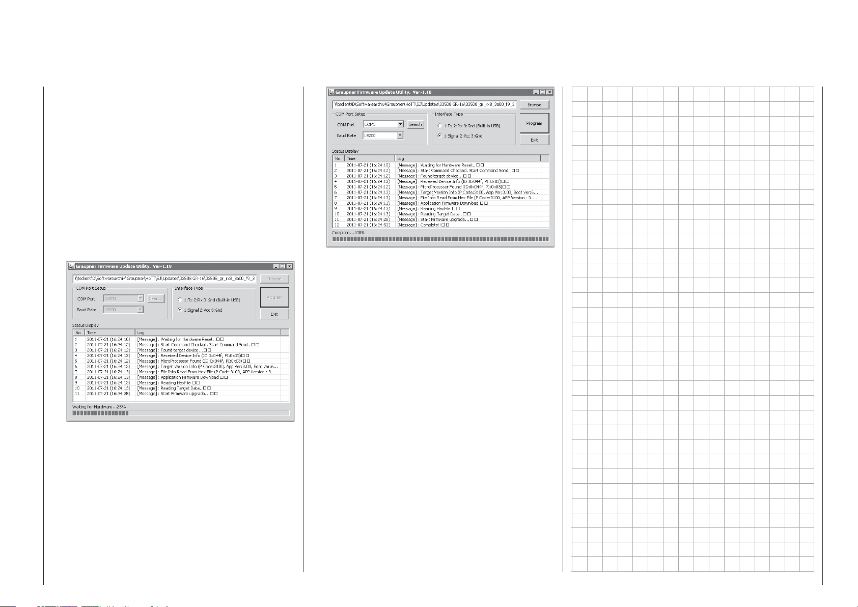
Activate the control labeled "Program". Wait for
the progress bar to start. Depending on the speed
of the computer being used, this may take several
seconds. Now switch on the receiver while holding
its SET button down. After a few seconds the
"Found target device …" message will appear
in the status display. Now you can release the
receiver's button. The actual fi rmware update
will begin autonomously after this message has
appeared.
However, if the receiver is not detected, the "Target
device ID not found" popup window will appear.
If this process terminates before reaching the
100 % mark, switch off your receiver's power supply
then try to start the update process all over again.
Do this by performing the above steps again.
The status display and progress bar will show you
the progress of the fi rmware update. The update
is concluded when the text "Complete … 100 %“
or "Complete!!" appears in the bottom line of the
status display.
t.
Both LEDs on the receiver will illuminate during
the update process. Upon successful conclusion
of the update process, the green LED will
extinguish and the red LED will begin to blink.
Switch the receiver off and remove the interface
cable. Repeat this procedure for any other
receivers present.
Receiver initialization4.
Following a successful update process you MUST
perform a receiver initialization procedure before
using the receiver again. This is necessary for
reasons of safety.
Do this by pressing and holding the receiver's SET
button then switching the receiver's power supply
on. Now release the SET button again. When you
subsequently switch the receiver on again, the
receiver's green LED will illuminate continuously
for about 2 or 3 seconds. Except for binding
information, all other settings that may have been
programmed into the receiver will now be reset
to factory defaults and will have to be re-entered
again if they are needed.
Receiver initialization
51
Installation notices
Receiver installation
Regardless of which Graupner receiver system you
use, the procedure is always the same.
Please pay attention that the receiver's antennas
must be mounted at least 5 cm away from all large
metal parts or any wiring that is not directly routed
out of the receiver itself. In addition to steel parts, this
also includes carbon fi ber parts, servos, fuel pumps
and all kinds of cables etc. Optimally the receiver
should be placed at a readily accessible location
that is well away from all other equipment. Under no
circumstances may servo cables be wrapped around
the antennas or routed close to it.
Please note that cables are subject to the
acceleration forces which occur during fl ight and
these forces may cause such cables, to shift in
position. Therefore be sure the cables in the vicinity
of the antennas are not able to move. Such moving
cables can cause reception disturbances.
Tests have shown that vertical (upright) antennas
provide the best results during wide-range fl ights. In
the case of diversity antennas (two antennas), the
second antenna should be oriented at a 90° angle to
the fi rst antenna.
The connectors designated "B + -" on the GR32 DUAL HoTT receiver are intended for battery
connections. The power supply is bussed across
all numbered connections so it can be attached
at any of these 16 connectors. However, due to
additional voltage losses associated with the traverse
connectors, connections 13 through 16 should not be
used for connecting the receiver's battery.
The function of every individual channel is determined
by the transmitter used, not by the receiver. However,
channel assignments can be changed in the receiver
by programming done in the »Telemetry« menu.
Nevertheless, it is recommended this be done on the
transmitter side via the "Transmitter output" option,
see page 218.
52
Installation notices
Several notices and suggestions for installing
remote control components into a model are
provided below.
Wrap the receiver in a foam rubber pad that is at 1.
least 6 mm thick. Attach the foam rubber to the
receiver with rubber bands so it will be protected
against vibration and/or the jars of a hard landing.
All switches must be installed such that they are 2.
not affected by exhaust gases or vibration. The
switch knob must be freely accessible over its
entire range of movement.
Mount servos on rubber bushes/spacers with 3.
hollow brass bearings to protect them from
vibration. Do not tighten the fastening screws
down too tight as this would negate the vibration
protection to be provided by the rubber bush/
spacer. Only when servo fastening screws are
properly tightened will this arrangement provide
security and vibration protection for your servos.
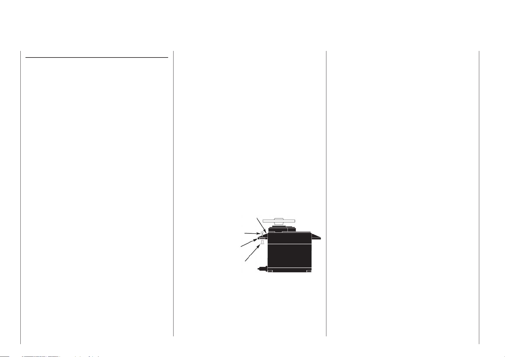
The fi gure below shows how a servo is mounted
properly. The brass bearings are to be pushed into
the rubber bushes/spacers from below.
Servo mounting lug
Retaining screw
Rubber grommet
Tubular brass spacer
Servo arms must be free to move throughout their 4.
entire range of motion. Pay attention that there are
no objects which could hinder servo arm motion.
The sequence in which servos are connected to the
receiver depends on the type of model. Follow the
connection layouts provided for this on pages 61 and 65.
Also observe the safety notices provided on pages 4 … 9.
In order to prevent uncontrolled movements of servos
connected to the receiver during startup
always fi
rst switch on the transmitter
and then the receiver
and when fi nished with operation
fi rst switch off the receiver
and then the transmitter.
When programming the transmitter, be sure that
electric motors cannot start running without control
or that a combustion motor equipped with automatic
starting cannot start up unintentionally. To be safe,
disconnect the receiver's drive battery or, in the case
of a combustion motor, disconnect the fuel supply.

For your notes
53

Term defi nitions
Control function, control, function input, control channel, mixer, switch, control switch, fi xed switch
To make use of this mc-16 HoTT manual easier, a
number of the terms used repeatedly throughout this
manual have been defi ned below.
Control function
A "control function" is to be perceived – initially
independent of its signal path – as a signal intended
to affect a given control function. For example, this
could be for throttle, rudder or aileron in a winged
aircraft or pitch, roll or crow for a helicopter.
A control function signal can be applied directly over
a single control channel or also through a mixer and
then applied over multiple control channels. A typical
example of multiple control channels is separately
operated aileron servos or the use of two roll or crow
servos in helicopters. The control function explicitly
includes the infl uence of the control's mechanical
travel on the respective servo. This can not only
be spread or compressed by software but even the
travel characteristic can be modifi ed from linear to
extremely exponential.
Control
"Controls" include all operating elements on the
transmitter, which are directly activated by the pilot,
that impose an effect on servos, speed controllers
etc. connected to the receiver. This includes:
both • joysticks for control functions 1 through
4, whereby these four functions can be freely
swapped around for both model types ("winged
aircraft" and "helicopters") by way of software
"Mode" settings, e.g. throttle left or right. The
joystick function for throttle/airbrake control is often
also referred to as the C1 control (channel 1).
both proportional controls located on the •
transmitter's sides, which are, for example,
given the designations SD1 (right-side "rotary
slider") and SD2 (left-side "rotary slider") in the
»Control adjust« menu, page 108 and 112.
the three • proportional sliders in the middle console
designated SR1 … 3, for example as shown in the
»Control adjust« menu, page 108 and 112,
all fi ve • proportional rotary controls on the
transmitter's front side, which are, for example,
given the designations DR1 … 5 in the
»Control adjust« menu, page 108 and 112,
the switches present, if they are assigned to a •
control channel in the »Control adjust« menu.
The proportional operating elements produce a direct
effect on servos which is commensurate with the
control's position whereas switch modules can only
effect a two or three increment change.
Just which of these controls and switches operate which
of the servos 5 … 16 (max.) is freely programmable.
Important notice:
Inputs 5 … 15 for helicopters and 5 … 16 for
winged aircraft are generally "free", i.e. not
assigned, in the transmitter's basic programming.
Function input
This is an imaginary point in the signal path and
must not be considered the same as the point on
the circuit board where the transmitter control is
connected. The choice of "Stick mode" and settings
in the »Control adjust« menu have their effect
"downstream" of these imaginary connection points.
Thus differences between the physical control's
number and the number of the downstream control
channel can indeed emerge.
Control channel
From the point at which a signal contains all control
information necessary for a particular servo – whether
directly from the physical control or indirectly by way
of a mixer – the term "control channel" is used. This
signal is only yet to be infl uenced by settings made in
the menus »Servo adjustment« and »Transmitter
output« before it leaves the transmitter's RF module.
Once it arrives at the receiver, this signal may still
be modifi ed by settings made in the telemetry menu
before fi nally being applied as a control quantity for
the respective servo.
Mixer
The transmitter's software contains a variety of mixer
functions. These can be used to apply one control
function to multiple servos or, conversely, to apply
multiple control functions to a single servo. Please
look over the numerous mixer functions in the text
beginning on page 159 of this manual.
Switches
The four standard toggle switches, the two 3-way
switches and both push-button switches can also
be incorporated into control programming. However,
these switches are generally intended for switching
program options, e.g. to start and stop timers, to
switch mixers on and off, or as a teacher/pupil
switchover, etc. Each of these switches can be
assigned any number of functions.
Appropriate examples are detailed in the manual.
Control switches
Since it is very practical to have some functions
automatically switched on or off for a certain control's
position (e.g. switch on/off of a stopwatch for
acquisition of model run time, automatic extension of
spoilers and other possibilities), eight control switches
have been integrated into
These software switches, designated "C1 … C8", are
merely defi ned by virtue of their contact state along
the physical control's course of travel by the touch of
a key. The switching action can be correlated to the
physical control's travel direction by software.
Of course control switches can also be freely
combined with the aforementioned physical switches
to solve even more complex problems.
There is a series of instructive examples which make
mc-16 HoTT software.
54
Term defi nitions

this programming child's play. Learn about this by
taking advantage of the programming examples
beginning on page 268.
Logical switches
These functions per
and/or logical switches or any combination of these to
be combined with one another to create logical "AND"
and "OR" functionality. A total of 8 logical switches,
"L1 … L8" can be programmed, see page 138.
Fixed switches FXI and FX
This type of switch turns a function, e.g. a timer,
permanently on (closed fi xed switch) or off (open fi xed
switch) or they can provide a fi xed input signal for a
control function, e.g. FXI = + 100 % and FX = -100 %.
For example, in fl ight phase programming, these
fi xed switches can be used to switch a servo or speed
controller between two settings.
mit two switches, control switches
Term defi nitions
55
Physical control, switch and control switch assignments
Principle procedure
Maximum fl exibility is offered by the mc-16 Hott
system when it comes to assigning standard
equipment operating elements to certain functions.
Since the assignment of controls and switches is
done in the same way, even though different menus
may be involved, it is appropriate at this point to
explain the fundamental programming technique so
that users can concentrate on the particular contents
when reading the detailed menu descriptions.
Physical control and switch assignments
The third column of the »Control adjust« menu
can be used to assign transmitter inputs 5 … 16 to
operate servos, both in any given joystick direction
(C1 … C4) as well as to assign any present control
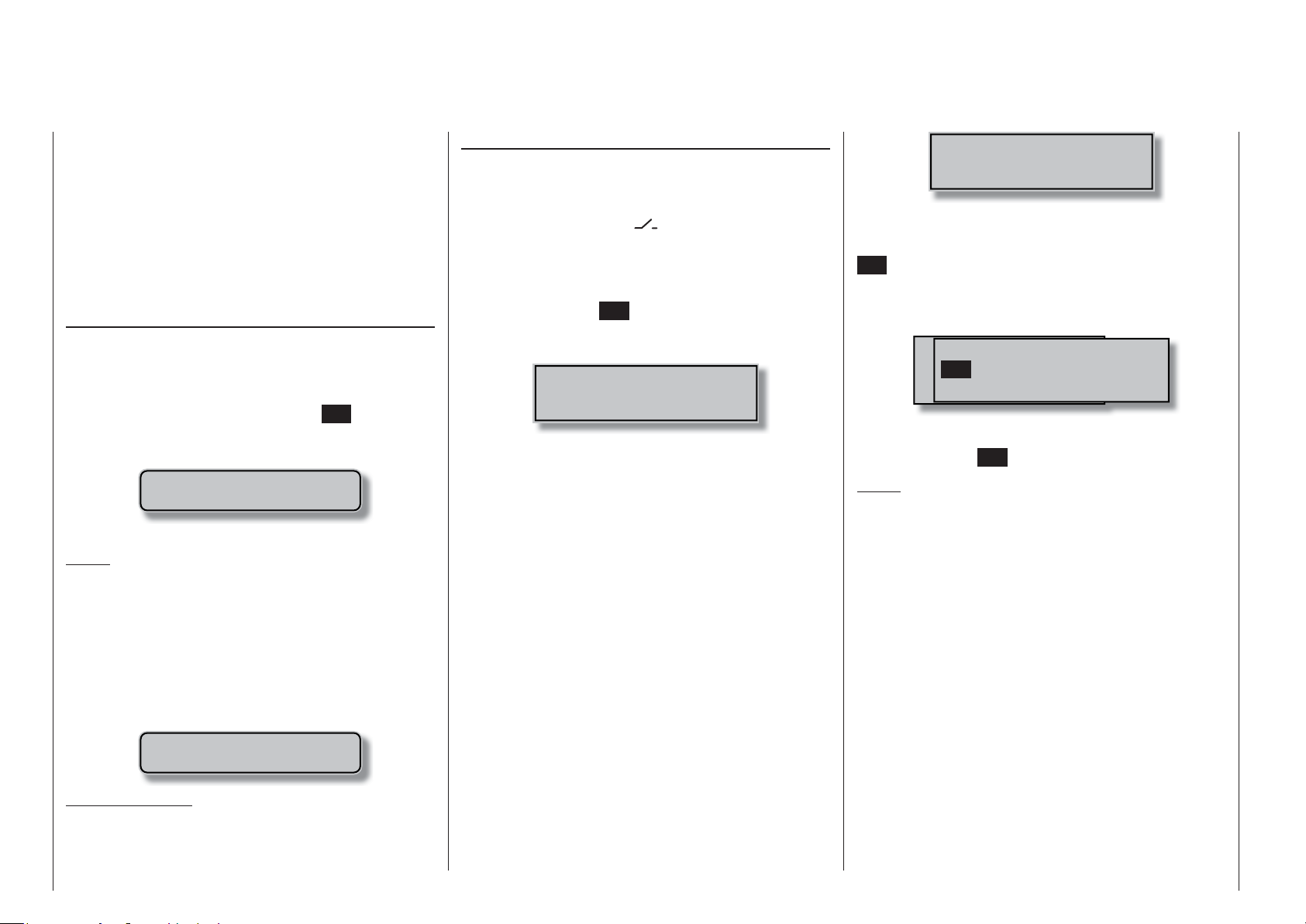
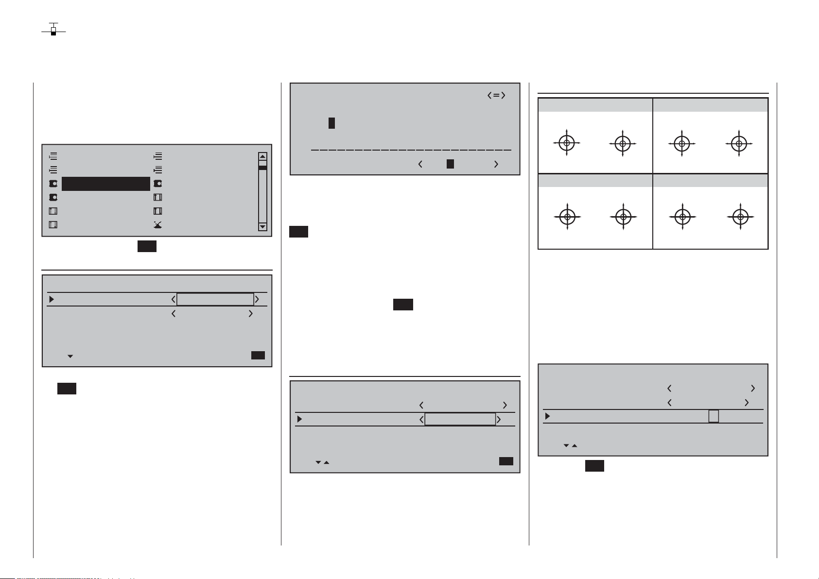
or switch. After tapping on the center SET key of the
right touch pad, the window shown below will appear
in the display.
Gewünschten Schalter
oder Geber betätigen
Now simply move the desired control or switch.
Notes:
The control will only be recognized beyond a certain
amount of travel.
moved back and forth until the correct assignment
is shown in the display. If adjustment travel is
insuffi cient, activate the control in the other direction.
On the other hand, if the »Control switch« menu,
page 135, is used to assign a control, the message
shown below will appear:
Important notice:
Controls to be assigned MUST be pre-assigned in
the »Control adjust« menu to one of the inputs 5
through 16!
Therefore these controls can be
Move desired
control adj.
Switch assignment
Wherever programming permits a switch to be
assigned, a switch symbol will appear in the screen's
bottom display line.
Use the selection keys in the left or right touch pad to
select the appropriate column.
How to assign a switch
Briefl y touch the 1. SET key of the right touch pad.
The message shown below will appear in the
screen.
Move desired switch
to ON position
(ext. switch: ENTER)
Now it is only necessary to put the selected switch 2.
into the desired "ON" position or, as described
at the right in "Assignment of external switches",
to select a switch from the list of "External
switches". This concludes the assignment. The
switch symbol to the right of the switch's number
indicates the current state of the particular switch.
Changing switch action
If the activation of a switch is to result in the opposite
action, put the switch or joystick in the desired OFF
position, again activate the switch assignment and
reassign the switch again so it will respond with the
desired action.
Clear switch
A switch which has been assigned as described
under point 1 can be cleared with a brief
simultaneous tap on the or key combination
in the right key pad (CLEAR).
Assignment from the "external switch" list
Those menus in which the message …
Move desired switch
to ON position
(ext. switch: ENTER)
… appears permit the assignment of switches
belonging to the so-called "external switches".
Do this by confi rming the message text with the
SET key. A new window will appear with a list of the
eight control switches "C1 … C8", followed by two
so-called "FX" fi
switches "L1 … L8".
Use the selection keys in the left or right key pad to
select the desired switch then assign it with a brief
tap on the center SET key of the right touch pad.
Notes:
Switching f
be better implemented from a certain freely
programmable control position rather than
switching them manually with a normal switch.
To this end, there are a total of 8 so-called "control
switches", C1 … C8, available whose switching
direction can be established, even inverted, in the
»Control switch« menu, page 135.
Two switches and/or also control switches can be •
combined with one another to form the logical "AND"
or "OR" functions via the »Logical switch« menu,
see page 138. A total of 8 logical switches "L1 … L8"
(as well as another 8 inverted logical switches with
inverted switching direction) are available.
The result of a logical switch function can also
be used as an input for another logical switch
function. Refer to the appropriate menu for more
details about this.
xed switches and the eight inverted
M wünschten Schalter
Control/Logic/fix switch
C3C1
to die EIN Position
(erw. Schalter: SET)
C2 C4 C5 C6
C7
or some special functions may •
FX FXi L1 L2
C8
56
Physical control, switch and control switch assignments

The two FX switches switch a function on "FXI" or •
off "FX
All other switches mentioned can have multiple •
assignments. Pay attention that you do not
UNINTENTIONALLY assign reciprocally confl icting
functions to a single switch. If necessary, note
down the given switch functions.
Typical applications:
Shut-off of an on-board glow plug heater upon •
underrun or overrun of an idle threshold point
programmed for the C1 joystick. In this case
the glow plug heater switch is controlled by a
transmitter mixer.
Automatic switch on/off of the timer to measure •
pure "fl ight time" for a helicopter by way of a
control switch on the throttle limiter.
Automatic switch off of the "AI • Rud" when
brake fl aps are extended, for example to adapt
the roll of a model to the ground when making a
landing on a slope without inducing a change of
fl ight direction due to infl uence on the rudder.
Extending landing fl aps with elevator trim adjustment •
during a landing as soon as the throttle stick is
moved beyond its switch point.
Switch on/off of the timer for measuring the •
operating time of electric motors.
" permanently.
Physical control, switch and control switch assignments
57

Digital trimming
Functional description and description of C1 cut-off
Digital trim with visible and audible indicators
Both joysticks are equipped for digital trimming. By
default, turning trim wheels will offset the joystick's
neutral position by 4 increments (out of a possible
100 steps per side). This offset is also reported
acoustically. A brief press on the trim wheel will
reset an existing trim offset back to "0". Any other
"zero points" can be specifi ed with the help of the
»Trim memory« menu. If fl ight phases have been
created and each assigned with a fi tting name in
the »Phase settings« and »Phase assignment«
menus, then these names will appear at the bottom
left in the »Trim memory« menu and their trim values
will be stored on a fl ight-phase specifi c basis.
The default 4-steps per click increment range placed
in every new model memory upon initialization can
be changed at any time in the »Stick mode« menu,
page 104 or 106, separately for each joystick plane,
in a range of 1 … 10 for fi xed-wing models and in
a range of 0 … 10 for helicopter models. (A trim
function can be deactivated by selecting "0" steps,
which can be advantageous in helicopters with
certain gyro systems.)
Current trim values are automatically stored
when a model memory change is made.
Furthermore, – except for the trim of the throttle/
airbrake joystick, the so-called "C1"(channel 1)
control function – digital trim can be set to operate
globally or on a fl ight-phase specifi c basis within a
memory location. This choice is made, separate for
each joystick plane, in the second column of the
»Stick mode« menu, page 104 or 106.
The "cut-off trim" function, known from other •
Graupner remote control systems in the mc and
mx series, and typically described in this section
can be realized with the help of the "Thr. CutOff"
option in the »Basic settings, model« menu,
see page 81 and 90.
Notes:
Finding the mid-point position during a fl ight is •
easy and can be done without even looking at the
display. A brief press on the trim wheel will reset
trim to "0" or, in the »Trim memory« menu, will
reset a stored fl ight-phase specifi c trim value.
58
Digital trimming

For your notes
59
Winged models
Convenient support is provided for up to four aileron
servos and four fl ap servos on normal models or, for
V tail and fl ying wing/delta models, up to two aileron/
elevator servos plus four fl ap servos.
The majority of motorized and glider models belong
to the tail unit type "normal" and are equipped with
one servo each for elevator, rudder and ailerons
in addition to a motor throttle or electronic speed
controller (or for brake fl aps in the case of a glider
model). Beyond this, tail unit type "2 HR Sv 3+8"
permits the connection of two elevator servos to
receiver outputs 3 and 8.
"V-tail" is to be selected from the »Model type« menu
if the model has a V-tail instead of a "normal" tail.
This V-tail option provides coupled control functions
for elevator and rudder such that both tail fl aps – each
controlled by a separate servo – are able to handle
both elevator and rudder functionality.
For delta and fl ying wing aircraft models, aileron and
elevator functionality is affected by way of a common
rudder fl ap on the trailing edge of each side (right and
left) of the wing. The program contains appropriate
mixer functions for both servos.
If ailerons, and conditionally the fl aps, are each
actuated with two separate servos then settings can
be made for differentiated control of all aileron and
fl ap pairs in the »Wing mixers« menu, i.e. settings
for downward rudder throw independent of upward
throw. And fi nally, the positioning of fl aps can also
be controlled by one or even more of the three
proportional sliders or the seven proportional rotary
controls.
Alternatively, there is a phase-dependent trim function
available for fl aps, ailerons and elevators in the
»Phase trim« menu.
Up to 8 fl ight phases can be programmed into each of
the 80 model memory locations.
Except for C1 trim, digital trim will be stored on a
fl ight-phase basis. C1 trim permits easy location of a
carburetor idle setting.
Two timers are always available for fl ight operation.
The transmitter operating time expired since the last
battery charge is also displayed.
All transmitter controls and switches can be assigned
in the »Control adjust« menu to inputs 5 … 16 with
almost no restrictions.
The "Dual Rate" and "Exponential" functions for
ailerons, rudder and elevators are separately
programmable and each are convertible between the
two variations on a specifi c fl ight-phase basis.
In addition to 8 freely allocatable linear mixers, 4 curve
mixers (»Free mixers« menu) and 4 dual mixers
(»Dual mixer« menu) there are also fl ight-phase
dependent 8-point curves available to control channel
1 (throttle/brake), see »Channel 1 curve« menu).
Depending on the number of wing servos, fi xed-
defi nition mix and coupling functions can be selected
from a list in the »Wing mixers« menu.
Multi-fl ap menu: control of fl aps as ailerons, •
the infl uence aileron trim on fl aps controlled as
ailerons, fl ap differentiation, fl ap function throw
magnitude for all aileron and fl ap pairs, ailerons
controlled as fl aps, elevator mixer fl aps
Brake settings: butterfl y, differential reduction, •
elevator curves
aileron • rudder mixer
fl aps • elevator mixer
o
r
e
l
i
A
r
o
t
a
v
t
e
a
l
v
E
e
l
E
A
60
Winged models
AI, AI2
Airbrake-Function 1
AI
n
FL
p
a
l
F
r
o
FL
r
o
t
a
v
e
l
E
A
p
a
l
F
F
i
l
e
l
a
r
o
p
n
i
l
e
r
o
n
A
i
l
e
r
o
R
u
d
n
d
e
r
AI
p
F
a
l
r
e
d
d
u
R
n
o
r
e
l
i
A
t
o
r
a
v
e
l
E
F
l
a
p
r
o
p
t
a
a
l
v
F
e
l
E
right
F
l
a
n
p
o
r
e
l
i
A
left
Airbrake
Airbrake
Flap
Elevator
Rudder/Elevator
left
V-Tail
right
AI
AI2
A
I
F
L
FL
A
I
FL2
L
F
FL2
E
L
F
L
E
L
F
L
RU AI
EL AI
FL
F
L
A
I
AI2
F
L
A
I
AI
Brake
Brake
Brake
FL, FL2
Elevator
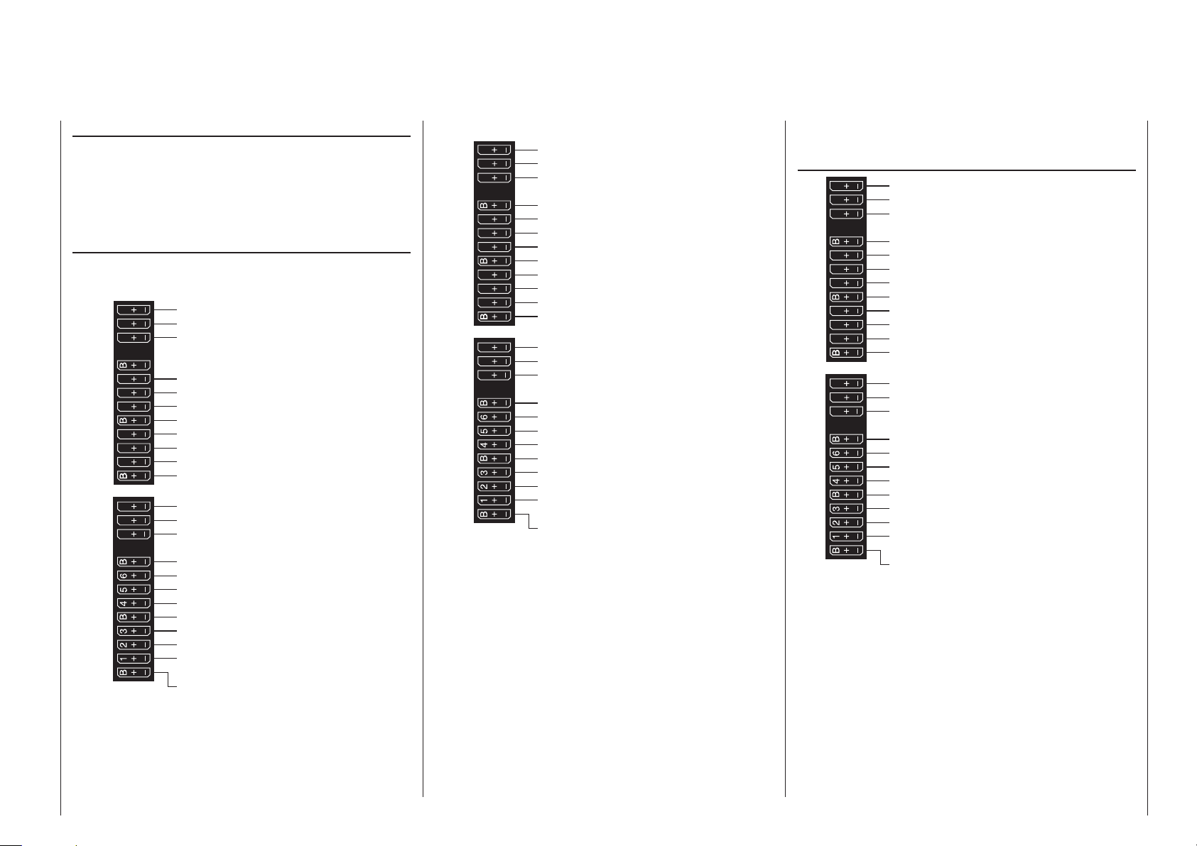
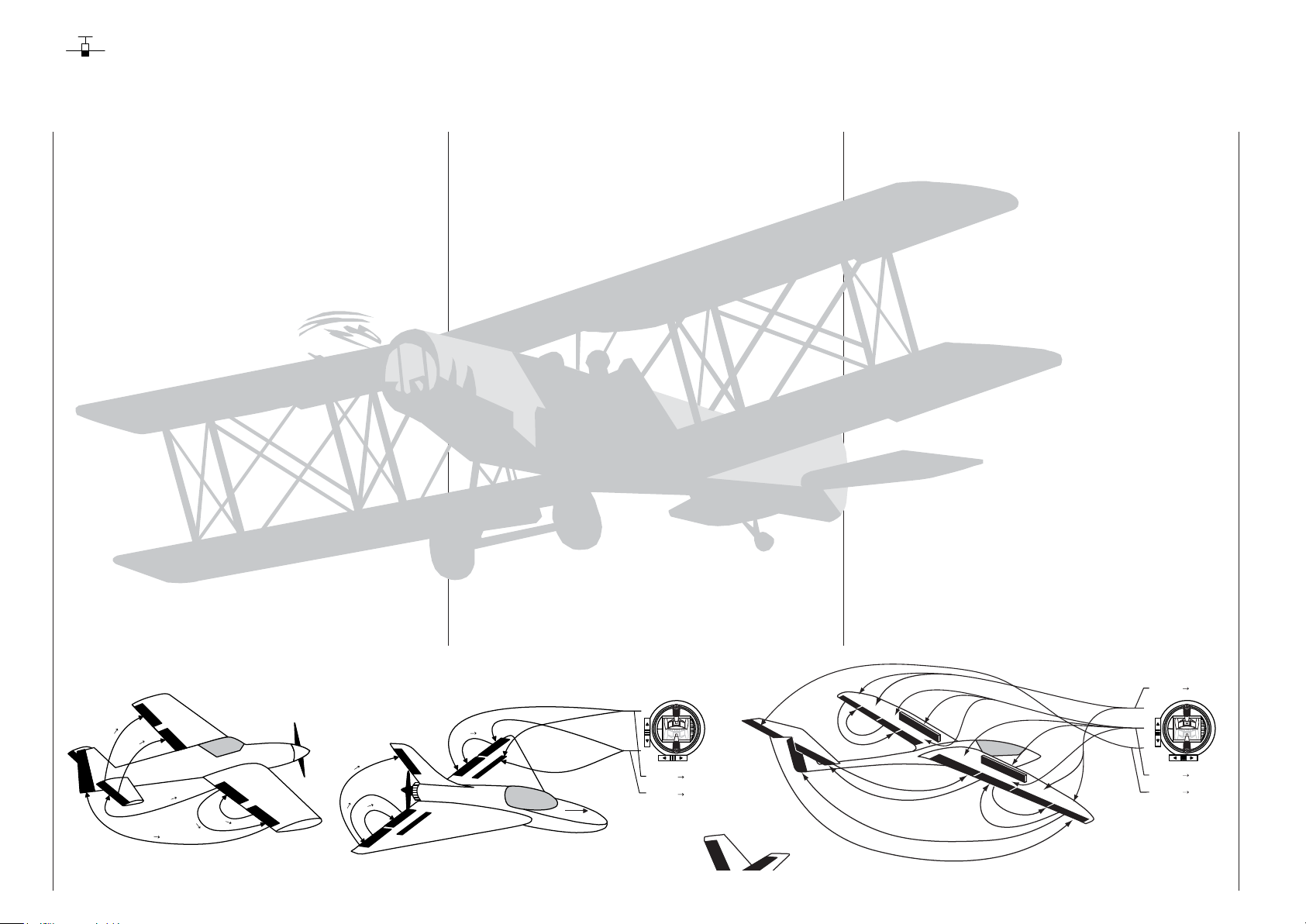
Installation notices
Servos MUST be connected to the receiver in the
sequence illustrated here.
Outputs which are not used are simply left empty. Also
be sure to follow the notices on the next pages.
Winged aircraft with and without motor having up
to 2 aileron servos and up to 4 fl ap servos …
… and tail plane type " normal" or "2 elevator
servos"
S
15 16
10 11 12
9
8
77
13 14 T
SUMO / SUMI-connection
free or aux. function
free or aux. function
Receiver power supply
free or AIL2 right or aux. function
free or AIL2 left or aux. function
free or flap2 right or aux. function
Receiver power supply
free or left flap2 or aux. function
free or 2nd Elevator or aux. function
Right flap or free or aux. function
Receiver power supply
Telemetry connection
free or aux. function
free or aux. function
Receiver power supply
Flap or left flap
Right aileron or aux. function
Rudder
Receiver power supply
Elevator or 1st elevator
Aileron or left aileron
Airbrake or throttle servo
or speed controller (electric motor)
Receiver power supply
… and tail plane type " V tail unit"
S
15 16
10 11 12
9
8
77
13 14 T
SUMO / SUMI-connection
free or aux. function
free or aux. function
Receiver power supply
free or right AIL2 or aux. function
free or left AIL2 or aux. function
free or right flap2 or aux. function
Receiver power supply
free or left flap2 or aux. function
free or 2nd elevator or aux. function
Right flap or free or aux. function
Receiver power supply
Telemetry connection
free or aux. function
free or aux. function
Receiver power supply
Flap or left flap
Right aileron or aux. function
Right elevator/rudder
Receiver power supply
Left elevator/rudder
Aileron or left aileron
Airbrake- or throttle servo
or speed controller (electric motor)
Receiver power supply
Delta/fl ying wing aircraft models with and without
motor having up to two aileron/elevator servos
and up to 2 fl ap/elevator servos
S
15 16
10 11 12
9
8
77
13 14 T
SUMO / SUMI-connection
free or aux. function
free or aux. function
Receiver power supply
free or aux. function or AIL2 / right EL
free or aux. function or AIL2 / left EL
free or aux. function or flap2 / right EL
Receiver power supply
free or aux. function or flap2 / left EL
free or aux. function
free or flap / right elevator
Receiver power supply
Telemetry connection
free or aux. function
free or aux. function
Receiver power supply
free or flap / left elevator
free or aux. function
free or rudder
Receiver power supply
AIL / elevator right
AIL / elevator left
Airbrake- or throttle servo
or speed controller (electric motor)
Receiver power supply
Winged models / Receiver layout
61
Because of orientation differences for installed servos
and their rudder linkages, the actuating direction of
some servos may be initially backward. The table
below provides remedies.
Model
type
V tail Rudder and
Delta,
fl ying
wing
Servo
direction
wrong
elevator reversed
Rudder correct,
elevators reversed
Elevators correct,
rudder reversed
Elevator and aileron
reversed
Elevator correct,
aileron reversed
Aileron correct,
elevators reversed
Remedy
Reverse polarity of
servos 3 & 4 in the
»Servo adjustment«
menu
Swap servos 3 & 4 on
the receiver
Reverse polarity of
servos 3 & 4 in the
»Servo adjustment«
menu AND swap them
on the receiver
Reverse the polarity
of servos 2 & 3 in the
»Servo adjustment«
menu
Reverse polarity of
servos 2 & 3 in the
»Servo adjustment«
menu AND swap them
on the receiver
Swap servos 2 & 3 on
the receiver
All "program descriptions" for menus relevant to a
winged aircraft model are marked with a winged
aircraft symbol …
… so only these menus need to be dealt with to
program a winged aircraft model.
62 Winged models - Servo direction wrong

For your notes
63
sledom retpocileH
The advanced developments incorporated into the
transmitter as well as those now in helicopter models
and their components like gyros, speed regulators,
rotor blades, etc. make it possible to master a
helicopter even in 3D acrobatic fl ight. On the other
hand, a beginner needs only a few settings to get
started with hovered fl ight training then, step-by-
step, take advantage of mc-16 HoTT features with
increasing expertise.
mc-16 HoTT program can operate all
The
conventional helicopters having 1 … 4 servos for
pitch control.
Seven fl ight phases plus autorotation are available
within a model memory, see menus »Control adjust«,
»Phase settings« and »Phase assignment«.
As with winged aircraft, here too, in addition to the
basic screen's standard timers there are additional
timers as well as a lap counter with fl ight-phase-
dependent stopwatch functionality which are available
for selection (menus »Timers (general)« and »Fl.
phase timers«).
Except for pitch/throttle trimming, digital trimming can
be stored as "global" for all fl ight phases or as "fl ight
phase specifi c". C1 trim permits easy location of an
idle setting.
The control assignments for inputs 5 … 16 is made
separately for each fl ight phase (»Control adjust«
menu).
A fl ight phase copy function is helpful during fl ight
trials (»Copy / Erase« menu).
"Dual Rate" and "Exponential" functions can be
coupled for roll, nick and tail rotor and programmable
in two variations in every fl ight phase.
There are 8 freely assignable linear mixers. There
are also 4 curve mixers that can be programed and
these can also be switched on or off, depending on
the fl ight phase, in the »MIX active/phase« menu.
Beyond this, there are also 4 dual mixers available.
The »Helicopter mixer« menu provides fl ight-
phase-dependent 8-point curves for the non-linear
char
acteristics pitch, throttle and tail rotor mixer as
well as two independent swashplate mixers each for
roll and nick. Independent of this, the control curve
of the channel 1 joystick can be defi ned with up to a
total of 8 points in every fl ight phase. The beginner
will initially only adapt the hover fl ight point to the
control middle for the non-linear characteristics.
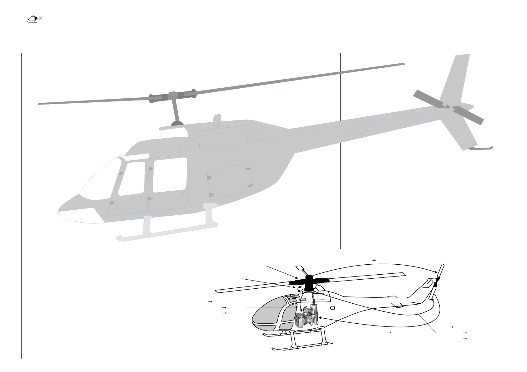
Pre-programmed mixers in the »Helicopter mixer«
menu:
Collective
Pitch Curve
Pitch curve (8-point curve)1.
.2 1C throttle (8-point curve)
Channel 1 3. tail rotor (8-point curve)
Tail rotor 4. throttle
.5 lloR throttle
.6 lloR tail rotor
Pitch-axis 7. throttle
Pitch-axis 8. tail rotor
Gyro suppression9.
Swashplate rotation10.
Swashplate limiter11.
The "Throttle limit" function (input Tl16 in the
»Control adjust« menu) allows the motor to be
started in any fl ight phase. The right-side proportional
rotary slider is assigned to input "Tl16" by default.
This "throttle limiter" establishes – depending on its
given position – the maximum possible throttle servo
position. This makes it possible for the motor to be
controlled in the idle range, if necessary even by the
proportional regulator. The throttle curves become
effective only when the proportional regulator is
pushed toward the full throttle direction.
l
i
a
R
o
T
t
o
1
l
e
n
n
a
h
C
r
64
Helicopter models
Swashplate
Roll
Throttle
Pitch-Axis
Channel 1
Rotation
Throttle
Throttle
Roll
T
a
i
l
R
o
t
o
r
e
T
l
r
t
h
t
o
Tail Rotor
Pitch-Axis
Channel 1
Tail Rotor
Tail Rotor
Notice for those transitioning from older
Graupner systems:
In comparison to previous receiver layouts, servo
connector 1 (pitch servo) and servo connector 6
(throttle servo) have exchanged places. Servos must
be connected to receiver outputs as illustrated at the
right in the bottom fi gure. Outputs which are not used
are simply left empty. More details about respective
swashplate types can be found on page 98 in the
»Helicopter type« menu.
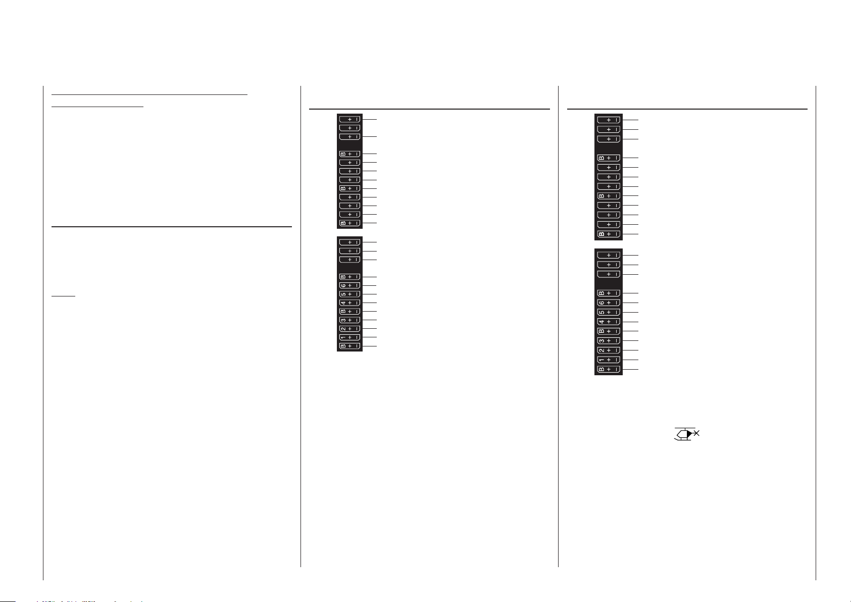
Installation notices
Servos MUST be connected to the receiver in the
sequence illustrated here.
Outputs which are not used are simply left empty.
Also be sure to follow the notices on the next pages.
Note:
A speed control is also to be connected to receiver
output "6" in order to take full advantage of the
throttle limiter's convenience and safety features, see
text beginning on page 117. See page 181 about this.
Receiver allocation for helicopter models with
1 to 3 swashplate servos
S
15 16
10 11 12
9
8
77
13 14 T
SUMO / SUMI-connection
free or aux. function
free or aux. function
Receiver power supply
free or aux. function
free or aux. function
free or aux. function
Receiver power supply
free or aux. function
frei or speed governor or aux. function
Gyro gain
Receiver power supply
Telemetry connection
free or aux. function
free or aux. function
Receiver power supply
Throttle servo or speed controller
free or aux. function
Tail rotor servo (gyro system)
Receiver power supply
Pitch-axis 1 servo
Roll-1 servo
Collective pitch or roll 2 or pitch-axis 2 servo
Receiver power supply
Receiver allocation for helicopter models with
4 swashplate servos
S
15 16
10 11 12
9
8
77
13 14 T
SUMO / SUMI-connection
free or aux. function
free or aux. function
Receiver power supply
free or aux. function
free or aux. function
free or aux. function
Receiver power supply
free or aux. function
free or speed governor or aux. function
Gyro gain
Receiver power supply
Telemetry connection
free or aux. function
free or aux. function
Receiver power supply
Throttle servo or speed controller
Pitch-axis 2 servo
Tail rotor servo (gyro system)
Receiver power supply
Pitch-axis 1 servo
Roll 1 servo
Roll 2 servo
Receiver power supply
All menus relevant to helicopter models are marked
in the "program descriptions" section with a helicopter
symbol …
… so only these menus need to be dealt with to
program a helicopter model.
Helicopters / Receiver layout
65
Detail program description
Loading a new memory location
Anyone who has worked through to this part of
the manual has certainly already tried out a bit of
programming. Nevertheless a detailed description of
every menu should not be left out.
This section begins with the loading of a "free"
memory location, a procedure which would be
performed if a new model was being "programmed".
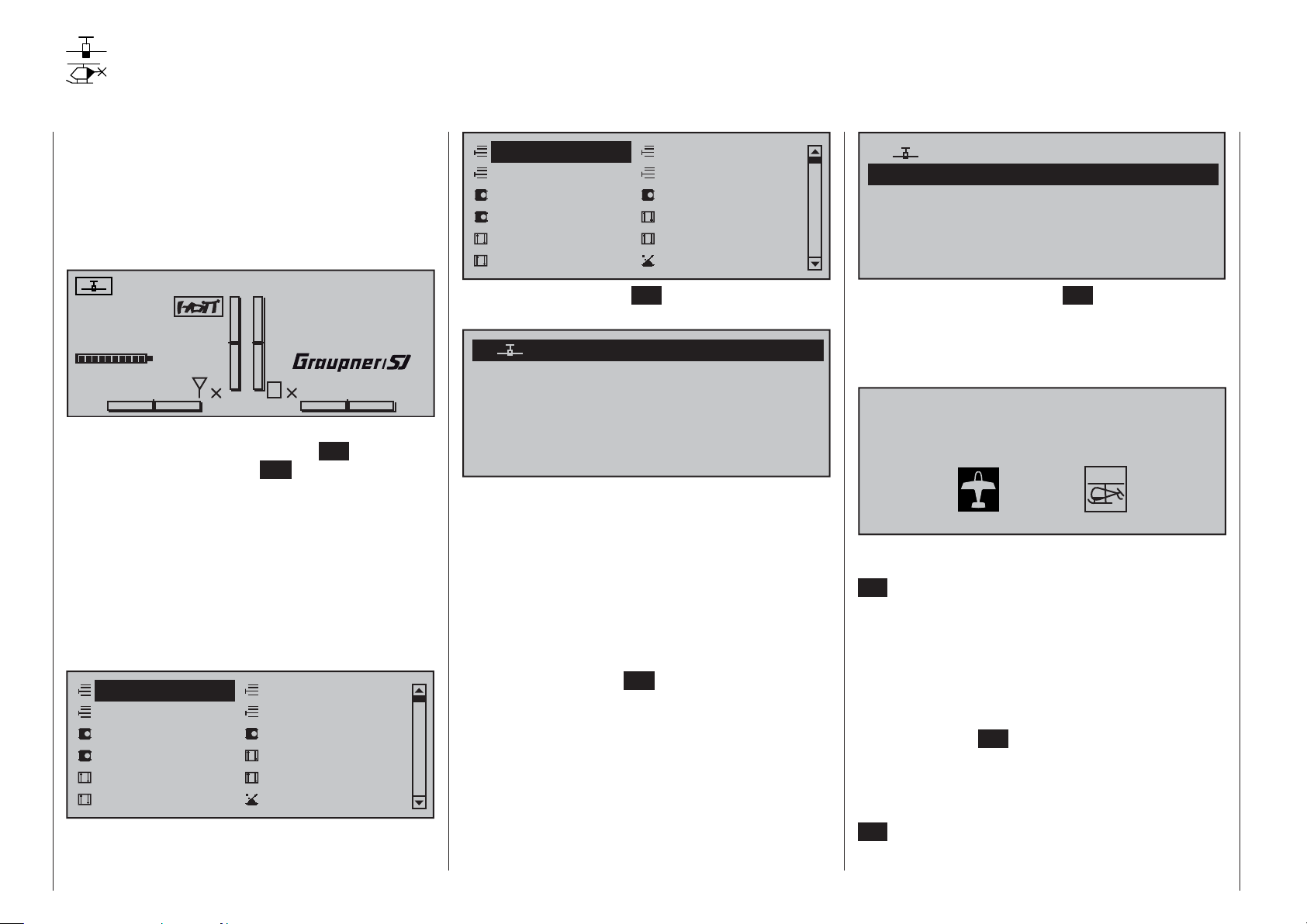
#01
4.1V
0
0:00h
00:00h
Stop watch
Flight tim
K78
V
M
0
RX VOLT:0.0v
0:00.0
0:00.0
00
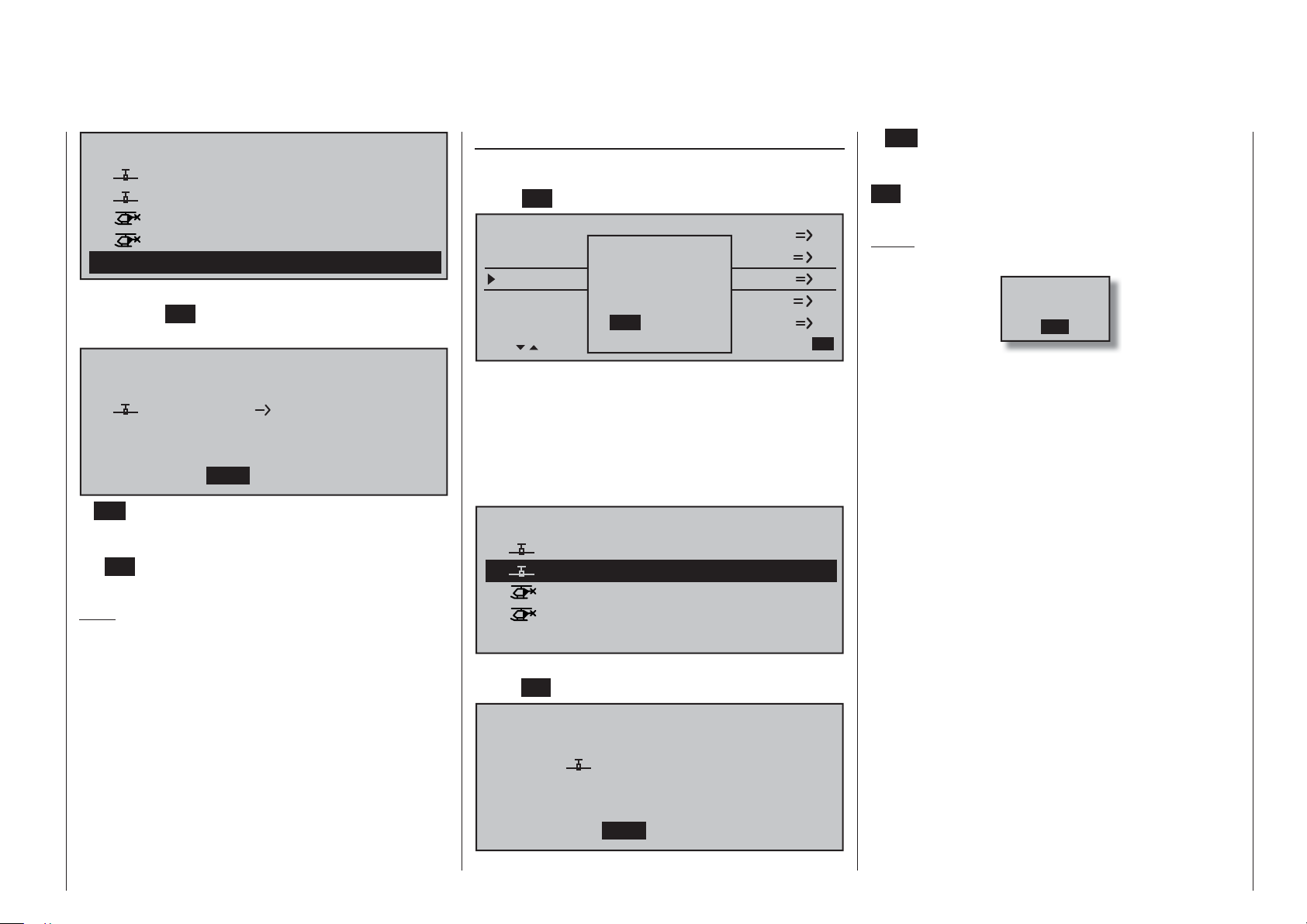
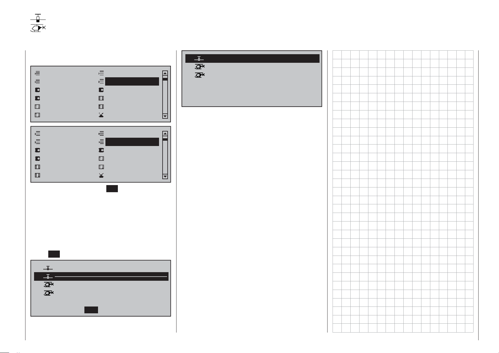
From the basic display, a jump to the "Multi-function
list" is made with a tap on the center SET key of the
right touch pad. (The center ESC key of the left touch
pad will cause a jump back to the basic display.)
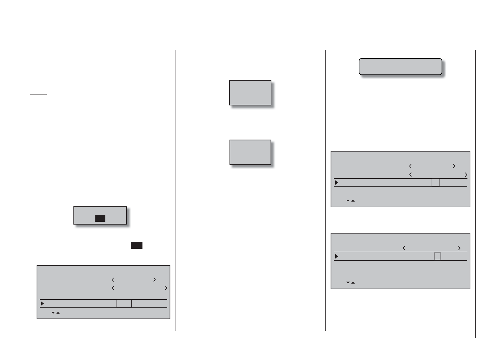
By default, when the multi-function list is called for
the fi rst time after switching on the transmitter, the
»Model select« menu option will be active and
displayed in inverse video. Otherwise use the
or selection keys of the left or right touch pad to
select the »Model select« menu option , whereby the
upper of the two following fi gures shows a selection
list for a fi xed-wing model and the lower shows the
selection list for a helicopter model.
Model select
Suppress codes
Base setup model
Servo adjustment
Control adjust
Channel 1 curve
Copy / Erase
Suppress models
Model type
Stick mode
Dual Rate / Expo
Switch display
Model select
Suppress codes
Base setup model
Servo adjustment
Control adjust
Channel 1 curve
Copy / Erase
Suppress models
Helicopter type
Stick mode
Dual Rate / Expo
Switch display
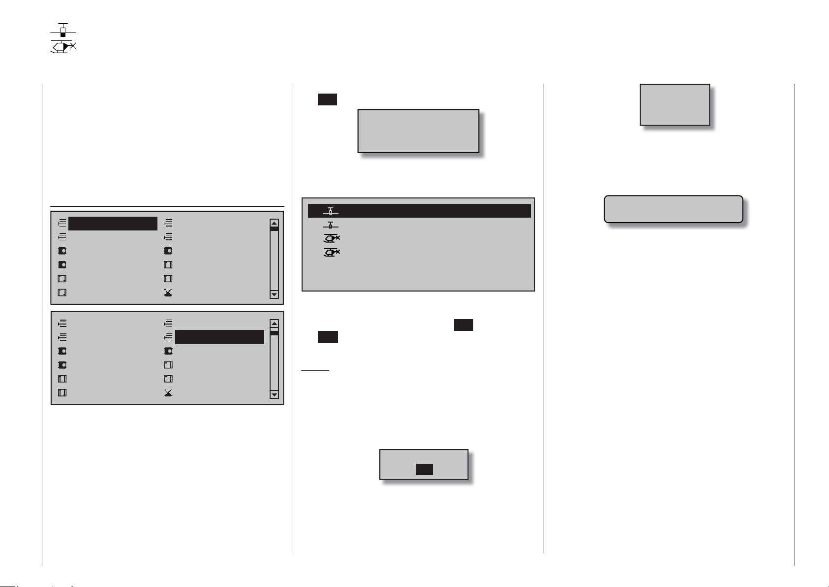
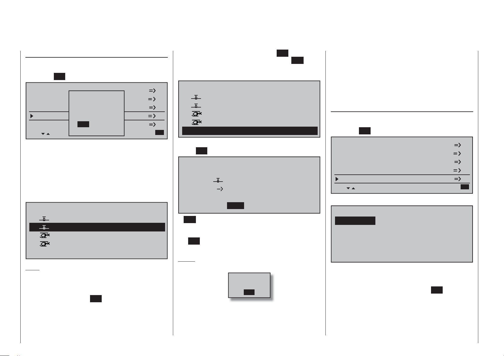
Tap briefl y on the center SET key of the right touch
pad to open this menu option:
01
02
03
04
05
06
free
free
free
free
free
00:12h
E16
In the transmitter's delivered state, the fi rst model
memor
y is initializ
and the receiv
ed to the "
er in the delivery is "bound" to this
fi x
ed-wing
model
" type
model. The time display located near the line's middle
indicates the overall operating time of the respective
model memory.
The remaining memory locations, marked with
free", are still unoccupied and therefore
"
also "non-bound". If you wish to program a fi xed-wing
model then, after leaving the »Model select« menu
with a tap on the center ESC key of the left touch pad,
programming of the model can begin right away … or
now use the or keys of the left or right touch pad
to select one of the free memory locations …
01
02
03
04
05
06
free
free
free
free
free
00:12h
R16
… and then tap on the center SET key of the right
touch pad to confi rm the choice.
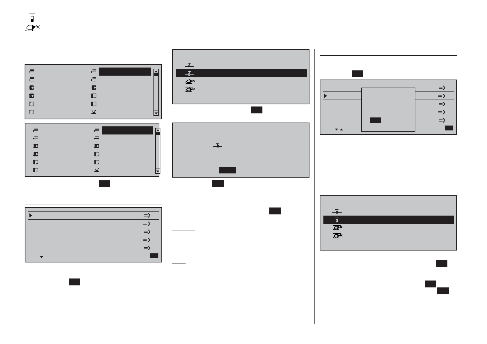
Afterward you will be prompted to select the basic
model type, i.e. either "winged model" or "helicopter
model".
Select model type ( free model memory )
Use the or keys of the left or right touch pad to
select the basic model type then tap on the center
SET key of the right touch pad. This initializes the
selected model memory with the selected model type
and the display will return to the base screen. The
memory location is now accordingly occupied.
However, if you wish to begin with a helicopter,
select one of the memory locations marked
free" with the or keys of the left or
"
right touch pad then confi rm the selection with a brief
tap on the center SET key of the right touch pad. You
will be now be prompted to specify the basic model
type, in this case the "helicopter model". Select the
appropriate symbol with the or keys of the left
or right touch pad then again tap briefl y on the center
SET key of the right touch pad to confi rm the choice.
This initializes the selected model memory with the
66 Detail program description - Loading a new memory location
selected model type and you can now program your
model into this model memory.
Changing over to another model type is still possible
if you fi rst erase this memory location (»Copy /
Erase« menu, page 70).
Notes:
If, from the base screen, the currently active model •
memory is to be erased then immediately after the
erase action one of the two model types, "Winged"
or "Heli" must be defi ned. You cannot avoid this
selection even if you switch the transmitter off.
When the transmitter is switched on again the
undesired occupation of the that model memory will
have to be erased from another memory location.
If a non-active memory location is erased, it will
subsequently be marked as "free" in the
"Model select" menu.
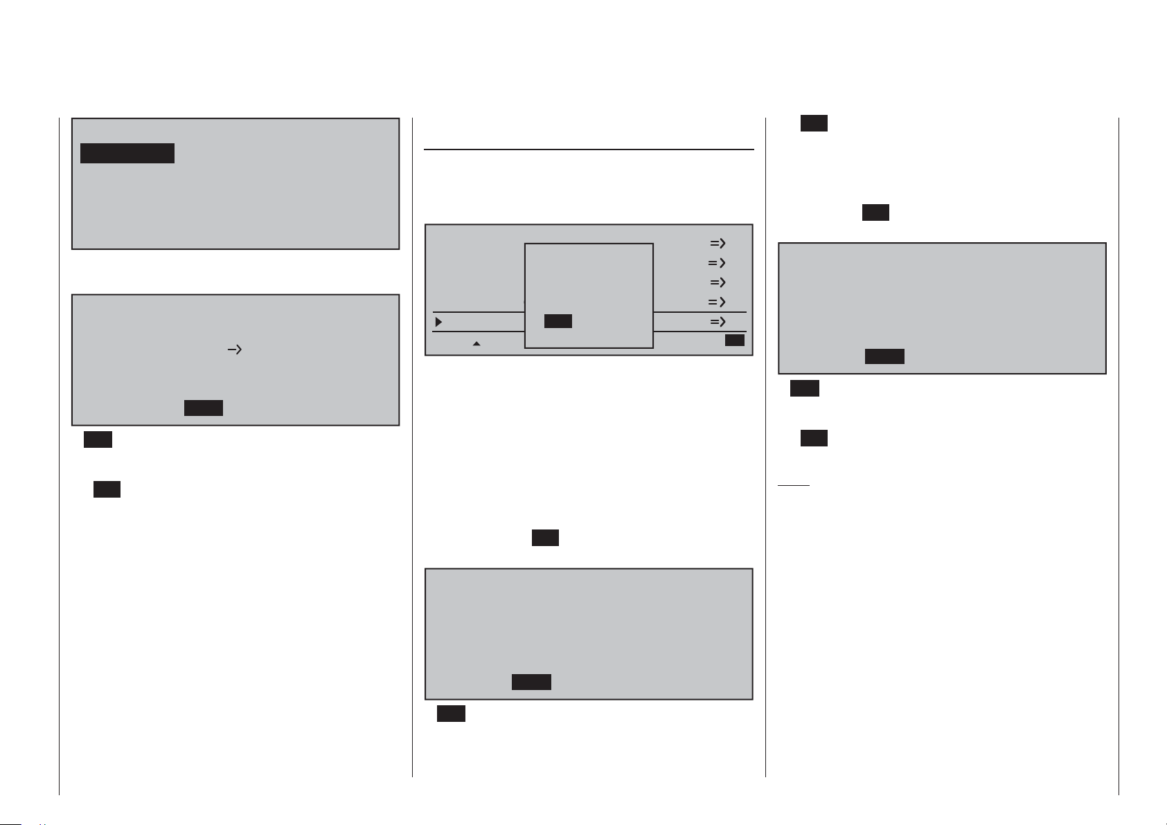
After the selected model memory is initialized with •
the desired model type, the display will switch to
the base screen of the freshly occupied model
memory. At this time the warning …
BIND. N/A
OK
… will appear for several seconds as notifi cation
that a binding connection to a receiv
availab
A brief tap on the center SET key of
le".
er is "not
the right touch pad will cause a direct jump to the
appropriate option.
BASIC SETTINGS, MODEL
Model name
Info
Stick mode
Module
HoTT
SEL BD1 BD2 BD3 BD4
bind
n/a
1
n/a
n/a
Further details about binding a receiver can be
found on page 77 or 85.
At the right and above the aforementioned "BIND. •
N/A" warning message, the warning …
Fail Safe
setup
t.b.d.
… will appear (also for just a few seconds) to
indicate that no no failsafe settings have yet been
made. More about this can be found on page 208.
If the screen should display the warning …•
Throttle
too
high!
… then move the throttle joystick, or the limiter for
a helicopter
, (b
y def
ault this is rotar
y slider SD1)
into its idle position.
Whether or not this warning appears also depends
on the settings selected f
or the "Motor on C1"
and "Pitch min." options in the »Model type«
menu, see page 94, or »Helicopter type« menu,
see page 98. For winged aircraft models, select
"None" to deactivate this message if you have no
motor
to enter.
If the transmitter already has occupied model •
memories then sub-menus of the »Copy / Erase«
menu will display a pictograph of the selected
model type at the respective memory location
followed by a blank line or the model name which
was entered in the »Basic settings, model«
menu, page 76 or 84. To the right of this will be as
display of the model operating time and, if present,
"Info" about the model.
If battery voltage is too low, the model switchover •
cannot be made due to reasons of safety. An
appropriate message will appear in the screen:
not possible now
voltage too low
As a basic principle, there are four different ways to
assign the four control functions, aileron, elevator,
rudder and throttle or br
ake fl aps for winged models
as well as rolling, pitching, tail rotor and throttle/
pitch for helicopter models, to the two joysticks. Just
which of these methods is used depends on the
preferences of the individual model pilot. This function
is set for the currently active model memory in the
"Stick mode" line of the »Basic settings, model«
menu, page 76 or 84.
BASIC SETTINGS MODEL
Model name
Info
Stick mode
Module
HoTT
bind
n/a
1
n/a
n/a
SEL
If this setting is desired as a default for future models,
the setting can also be entered into the »General
basic settings« menu, page 258:
GENERAL BASIC SETTINGS
Owners name
Pre-set stick mode
Pre-set modulation
Pre-set DSC Output
1
HoTT
PPM10
SEL
It should be noted here once again that, in the interest
of greatest fl exibility in combination with the prevention
of unintentional operating errors, no controls are
preassigned to control channels 5 … 16 by default.
This means that, in the system's delivered state,
Detail program description - Loading a new memory location
67

only servos attached to receiver outputs 1 …
4 can typically be operated by the two joysticks
and that any servos attached to receiver
connectors 5 … 16 (max) will remain in their
middle positions. A newly initialized helicopter
model is also able to more-or-less move servo
6 – depending on the position of the right-side
proportional rotary slider, which is the default throttle
limiter control. With either model type, this situation
will only change after appropriate assignments have
been made in the »Control adjust« menu.
On the other hand, if a newly initialized model
memory is to be put into operation then it MUST
fi rst be appropriately "connected" with one or more
receivers before the servos attached to the receiver/s
can be operated. More about this can be found in the
section "Binding" on page 77 or 85.
A fundamental description of programming steps
for a winged aircraft model can be found in the
programming examples section beginning on 268,
or for helicopter models beginning on page 308.
The menu descriptions below are arranged in the
sequence individual menus are listed in the multifunction list.
68 Detail program description - Loading a new memory location
Model select
Call up model 1 … 80
The basic operation of the transmitters keys was
explained on pages 28 and 29 and, on the previous
double-page, explanations were provided for
navigating to the multifunction list and about how
to make allocations for a new model memory. At
this point we now wish to begin with the "normal"
description of individual menu items in the sequence
they are arranged in the transmitter. Therefore we will
begin with the menu …
Model select
Model select
Suppress codes
Base setup model
Servo adjustment
Control adjust
Channel 1 curve
Model select
Suppress codes
Base setup model
Servo adjustment
Control adjust
Channel 1 curve
As many as 80 complete model settings, including
digital trim values for the trim wheel, can be stored.
imming is stored automatically such that a
Tr
switchover from one model to another does not cause
a loss of current trim settings. To the right of the
model number, each occupied model memory line in
this display shows a pictograph of the model type as
well as the model's name entered for the model in its
»Basic settings, model« menu, page 76 or 84. The
code, if present, for the receiver "bound" to the model
memory location will appear after the model number.
Select the »Model select« menu with the selection
Copy / Erase
Suppress models
Model type
Stick mode
Dual Rate / Expo
Switch display
Copy / Erase
Suppress models
Model type
Stick mode
Dual Rate / Expo
Switch display
keys of the left or right touch pad then briefl y tap on
the SET key of the right touch pad.
Attention!
Switch-OFF
the Receiver first!
If this message appears, there is a telemetry connection
to an operationally ready receiver system. Switch that
receiver system off.
01
02
03
04
05
06
Now, with the selection keys of the left or right
touch pad, select the desired model memory from the
list and activate it with a tap on the SET key. A tap on
the ESC key will cause a return to the previous menu
page without activating a model change.
Notes:
Ultimate
Starlet
BELL47G
free
free
If, after a model change, the "Throttle too high" •
warning appears, the throttle/pitch joystick (C1)
or the throttle limiter – by default, the right-side
proportional rotary slider – is too far in the full
throttle direction.
If a model change causes the message …•
… to appear then binding settings should be
checked.
If a model change causes the message …•
1234g/080811
Test
trim needed
BIND. N/A
OK
01:23hR16Graubele
00:44hR12
00:33hR08
00:22hR08
Fail Safe
setup
t.b.d.
… to appear then respective failsafe settings
should be checked.
If battery voltage is too low, the model switchover •
cannot be made due to reasons of safety. An
appropriate message will appear in the screen:
not possible now
voltage too low
Detail program description - Model select
69
Copy / Erase
Erase or copy model model, copy from or to SD card, copy fl ight phases, store/cancel changes
Use the selection keys of the left or right touch
pad to select the »Copy / Erase« menu …
Model select
Suppress codes
Base setup model
Servo adjustment
Control adjust
Channel 1 curve
Model select
Suppress codes
Base setup model
Servo adjustment
Control adjust
Channel 1 curve
… then briefl y tap the center SET key of the right
touch pad.
Erase model
Erase model
Copy model –> model
Export to SD
Import from SD
Copy flight phase
Copy / Erase
Suppress models
Model type
Stick mode
Dual Rate / Expo
Switch display
Copy / Erase
Suppress models
Helicopter type
Stick mode
Dual Rate / Expo
Switch display
=>
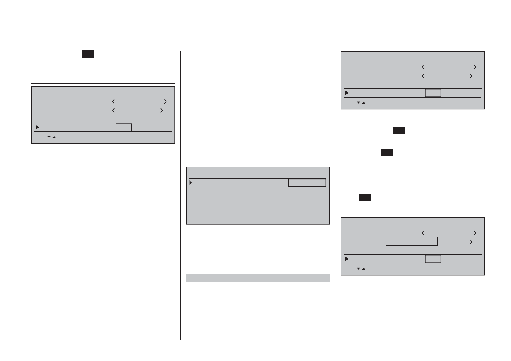
Select the "Erase model" sub-menu with the
selection keys of the left or right touch pad then
briefl y tap on the SET key.
Choose the model to be erased with the
selection keys of the left or right touch pad …
Select model to be erased :
01
02
03
04
… whereby another tap on the SET key will cause the
confi r
… to appear. A NO response will cause the process
to be canceled and a return to the previous screen.
Selecting the YES response with the selection key
of the left or right touch pad followed by confi rmation
of the selection with a brief tap on the SET key will
erase the selected model memory.
Caution:
This erase process cannot be undone. All data
in the selected model memory will be erased
completely.
Note:
If the currently active model memory is to be
erased, a model type "Winged" or "Heli" must be
defi ned immediately after the erase process. If,
however, an inactive memory location is erased, it
will subsequently appear in "Model select" list as
"
free".
Graubele
Ultimate
Starlet
BELL47G
mation request …
Model really
02
to be erased?
1234g/080811
Test
trim needed
Ultimate
NO
01:23hR16
00:44hR12
00:33hR08
00:22hR08
YES
Copy model model
Select the »Copy model model« sub-menu with
the selection keys of the left or right touch pad
then tap the SET key.
Erase model
Copy modelodell –> Modell
Export to SD-Karte
Import fromn von SD-Karte
Copy flight en kopieren
Please select
RF on/off?
=>
OFFON
If the message shown above should appear, the
transmitter's RF module is still active. Switch the RF
module off as described on page 80 then also, if a
receiv
er system is currently switched on, switch off
that receiver too. This is to be done for reasons of
safety.
Choose the model to be copied with the selection
keys of the left or right touch pad …
Copy from model:
01
02
03
04
05
… then, following the change into the "Copy to
model" windo
key of the r
can be selected with the selection keys of the left
or right touch pad. Yet another tap on the SET key
will then confi rm the copy process or a tap on ESC
key will cause the copy to be canceled. A memory
location which is already occupied can be overwritten.
Graubele
Ultimate
Starlet
BELL47G
free
w caused b
ight touch pad, the destination memory
1234g/080811
Test
trim needed
y another tap on the
01:23hR16
00:44hR12
00:33hR08
00:22hR08
SET
70 Detail program description - Copy / Erase
Copy to model:
01
02
03
04
05
Graubele
Ultimate
Starlet
BELL47G
free
1234g/080811
Test
trim needed
01:23hR16
00:44hR12
00:33hR08
00:22hR08
After confi rming the selected model memory with
a tap on the SET key, a confi rmation request will
appear:
Model really
02
Ultimate
05
free
to be copied?
NO
YES
A NO response will cancel the process and return
the screen to the originating screen. If the YES
response is selected and confi rmed with a tap on
the SET key then the selected source model will be
copied into the selected model memory destination.
Note:
In addition to model data, binding data is also copied
by this process. This means that a receiver system
which was/is bound to the original model memory can
also be operated by its copy without establishing the
bond again.
Exporting to SD card
Use the selection keys of the left or right touch
pad to select the »Export to SD« sub-menu then tap
on the SET key.
Erase model
Copy modeModell –> Modell
Export to SDach SD-Karte
Please select
RF on/off?
=>
Import from von SD-Karte
Copy flight sen kopieren
OFFON
If the message shown above should appear, the
transmitter's RF module is still active. Switch the
RF module off as described on page 80 then also, if a
receiver system is currently switched on, switch off that
receiver too. This is to be done for reasons of safety.
Choose the model to be exported with the
selection keys of the left or right touch pad …
export to SD-Card:
01
02
03
04
05
After confi
on the
SET key, a confi
Model really
export?
Graubele
Ultimate
Starlet
1234g/080811
Test
trim needed
BELL47G
free
rming the selected model memory with a tap
rmation request will appear:
02
Ultimate
NO
01:23hR16
00:44hR12
00:33hR08
00:22hR08
YES
A NO response will cancel the process and return
the screen to the originating screen. If the YES
response is selected then confi rmed with a tap on the
SET key, the selected model will be copied to the SD
card.
Notes:
Should the notice …•
SD-CARD
INSERT
OK
… appears instead of a screen for model
selection, there is no SD card in the transmitter's
card slot, see page 23.
In addition to model data, binding data is also •
copied by this process. This means that a receiver
system which was/is bound to the or
iginal model
memory can also be operated in the SAME
transmitter by its copy without establishing the
bond again.
An exported fi xed-wing model will be stored on •
the memory card in the \\Models\mc-16 folder
with a fi lename format of "aModelname.mdl"
and a helicopter model with a fi lename format
of "hModelname.mdl". On the other hand, if a
"nameless" model is exported, its data will be
stored on the memory card under "ahNoName.
mdl" or "hNoName.mdl", as appropriate.
Some special characters that can be used in •
model names are subject to specifi c restrictions
associated with the FAT or FAT32 fi le system used
by the memory cards and these special characters
will be replaced during the copy process with a
tilde (~).
A model fi le already on the memory having •
the same name as the fi le to be copied will be
overwritten without warning.
Detail program description - Copy / Erase
71
Importing from SD card
Use the selection keys of the left or right touch
pad to select the »Import from SD« sub-menu then
tap on the SET key.
Erase model
Copy modell –> Modell
Export to mnach SD-Karte
Import from von SD-Karte
Copy flight sen kopieren
Please select
RF on/off?
=>
OFFON
pad then confi rmed with a tap on the SET key, or the
process can be canceled with a tap on the ESC key.
A memory location which is already occupied can be
overwritten.
Import to model:
01
02
03
04
05
Graubele
Ultimate
Starlet
BELL47G
free
1234g/080811
Test
trim needed
01:23hR16
00:44hR12
00:33hR08
00:22hR08
card slot, see page 23.
In addition to model data, binding data is also •
imported by this process. This means that a
receiver system which was/is bound to the original
model memory can also be operated in the SAME
transmitter by its copy without establishing the
bond again.
Copy fl ight phase
Select the »Copy fl ight phase« sub-menu with the
selection keys of the left or right touch pad then
tap on the SET key.
If the message shown above should appear, the
transmitter's RF module is still active. Switch the RF
module off as described on page 80 then also
receiver system is currently switched on, switch off that
receiver too. This is to be done for reasons of safety.
Select the model to be imported from the SD memory
card with the selection keys of the left or right
touch pad.
import from SD-CARD:
01
02
03
04
Note:
The export date posted at the right end of each model
name line is represented in the format "year/month/
day".
After another tap on the SET key of the right touch
pad, the "import from SD-CARD" window will appear.
Now the destination memory location can be selected
with the selection keys of the left or right touch
Soarmaster
Extra 300
T-Rex 250
BellCobra
11/06/06 06:06
11/07/07 07:07
11/08/08 08:08
11/09/09 09:09
, if a
After confi rming the selected model memory with a tap
on the SET key, a confi
model
import?
A NO response will cancel the process and return
the screen to the originating screen. If the YES
response is selected and confi rmed with a tap on
the SET key then the selected source model will be
imported into the selected destination model memory.
Notes:
If the message …•
… appears instead of a screen for model
selection, there is no SD card in the transmitter's
rmation request will appear:
Extra 300
free
YES
05
NO
SD-CARD
INSERT
OK
Erase model
Copy model –> model
Export to SD
Import from SD
Copy flight phase
=>
In the "Copy fl ight phase" sub-menu …
Copy from phase:
1
3
5
7
… the fl ight phase to be copied (1 … 8 for fi xed-wing
models or 1 … 7 for helicopter models) is selected
with the selection keys of the left or right touch pad
then confi r
right touch pad. In the next window to appear …
med with a brief tap on the SET key of the
2
4
=>
6
=>
8
72 Detail program description - Copy / Erase
Copy to phase:
1
3
5
7
… a destination must be selected and it must be
confi rmed too. Another confi r
Phase to:
1 normal
to be copied?
NO
A NO response will cancel the process and return
the screen to the or
response is selected and confi
the SET key then the selected source model will be
imported into the selected destination model memory.
iginating screen.
2
4
=>
6
=>
8
mation request will follow:
2 Thermik
YES
If the
rmed with a tap on
YES
Storing changes permanently
Undoing changes
These two sub-menus permit programming changes
to be backed up immediately or to be undone
(restored) to the state when the model was called up
or the state of the last backup.
Export to SD
Import fromvon SD-Karte
Copy flight en kopieren
Store changes ft speichern
Undo changesgig machen
Please select
RF on/off?
=>
OFFON
If the message shown above should appear, the
transmitter's RF module is still active. Switch the RF
module off as described on page 80 then also
receiver system is currently switched on, switch off that
receiver too. This is to be done for reasons of safety.
Data is only backed up by "Store change" or a
switch from one model to another in the »Model
select« menu. Switching the transmitter on or off
will not store the permanently. To store changes
permanently, select the appropriate line then briefl y
tap on the center SET key of the right touch pad. The
confi rmation request shown below will appear:
, if a
the SET key then the changes made since the last
backup or model change will be stored permanently.
If, however, the changes made since the last
backup or model change are to be canceled, then
select the line "Undo change". Following a brief tap
on the center SET key of the right touch pad, the
confi rmation request shown below will appear:
Programming changes to be
reset to original?
NO
A NO response will cancel the process and return
the screen to the originating screen. If the YES
response is selected and confi
the SET key then the changes made since the last
backup or model change will be stored permanently.
Note:
When the transmitter is switched off, any changes
made will not be lose but they are not permanently
stored either. This means that a subsequent "cancel
changes" would reset memory to the state of the last
"permanent backup" (or model change).
YES
rmed with a tap on
Programming changes to be
store permanently?
NO
A NO response will cancel the process and return
the screen to the originating screen. If the YES
response is selected and confi
YES
rmed with a tap on
Detail program description - Copy / Erase
73
Suppress menus
Suppression of menus in the multifunction list
Use the selection keys of the left or right touch
pad to select the »Suppress codes« menu …
Model select
Suppress codes
Base setup model
Servo adjustment
Control adjust
Channel 1 curve
Model select
Suppress codes
Base setup model
Servo adjustment
Control adjust
Channel 1 curve
… then briefl y tap the center SET key of the right
touch pad.
Model select
Suppress models
Model type
Stick mode
Dual Rate / Expo
Suppress : SET
Model select
Suppress models
Helicopter type
Stick mode
Dual Rate / Expo
Suppress : SET
Copy / Erase
Suppress models
Model type
Stick mode
Dual Rate / Expo
Switch display
Copy / Erase
Suppress models
Helicopter type
Stick mode
Dual Rate / Expo
Switch display
Copy / Erase
Base setup model
Servo adjustment
Control adjust
Channel 1 curve
Copy / Erase
Base setup model
Servo adjustment
Control adjust
Channel 1 curve
In the menu which then appears, menu items which
are no longer needed or those which should not
be changed, can be blocked from appearing in th
multifunction list.
The option to be suppressed/displayed is selected
with the selection keys of the left or right touch pad
then its status is switched over with a tap on the
center SET key of the right touch pad.
Model select
Suppress models
Model type
Stick mode
Dual Rate / Expo
Suppress : SET
Model select
Suppress models
Helicopter type
Stick mode
Dual Rate / Expo
Suppress : SET
This can reduce the multi-function list considerably, in
some cases to only a few menus, thus substantially
improving clarity of the multi-function list. Options are
not deactivated by being suppressed. They will simply
no longer appear in the list. This also blocks direct
access to these functions.
Tip:
If you wish to forgo access-blockage to the multifunction list altogether, suppress the »Code lock«
menu in the multi-function list by way of this menu as
a precautionary measure. It is then not so easy for an
unauthorized person to lock up the transmitter.
Copy / Erase
Base setup model
Servo adjustment
Control adjust
Channel 1 curve
Copy / Erase
Base setup model
Servo adjustment
Control adjust
Channel 1 curve
74 Detail program description - Suppress menus
Suppress models
Suppression of model memory locations
Use the selection keys of the left or right touch
pad to select the »Suppress models« menu …
Model select
Suppress codes
Base setup model
Servo adjustment
Control adjust
Channel 1 curve
Model select
Suppress codes
Base setup model
Servo adjustment
Control adjust
Channel 1 curve
Copy / Erase
Suppress models
Model type
Stick mode
Dual Rate / Expo
Switch display
Copy / Erase
Suppress Models
Helicopter type
Stick mode
Dual Rate / Expo
Switch display
… then briefl y tap the center SET key of the right
touch pad.
Model memories which are rarely needed or to
which access is to be blocked for other reasons can
be hidden from the model selection list.
This also
clarifi es the overview layout for model selection.
The model to be suppressed/displayed is selected
with the selection keys of the left or right touch pad
then its status is switched over with a tap on the
center
SET key of the right touch pad.
01
03
04
05
06
07
Starlet
BELL47G
free
free
free
1234g/080811
trim needed
01:23hR16Graubele
00:33hR08
00:22hR08
01
02
03
04
05
Graubele
Ultimate
Starlet
BELL47G
Suppress :
free
1234g/080811
Test
trim needed
SET
01:23hR16
00:44hR12
00:33hR08
00:22hR08
A model memory which is "stricken through" will no
longer appear in the »Model select« menu.
Detail program description - Suppress models
75
Base setup model
Model-specifi c base settings for winged aircraft models
Before programming specifi c parameters, there are
some basic settings to be made which effect the
currently active model memory.
Use the selection keys of the left or right touch pad to
select the »Basic settings, model« menu …
Model select
Suppress codes
Base setup model
Servo adjustment
Control adjust
Channel 1 curve
Copy / Erase
Suppress models
Model type
Stick mode
Dual Rate / Expo
Switch display
… then tap the center SET key of the right touch pad.
!"#$%&’()
@ACDEFGHIJKLMNOPQRSTUVWXYZ[¥]^_
`abcdefghijklmnopqrstuvwxyz{|}~
¢ЗьйвдаезклипомДЕЙжЖфцтыщЦЬ
Model name
Now the desired characters can be selected with the
selection keys of the left touch pad. Move to the next
position to select the ne
selection key of the right touch pad or its center
SET key. A simultaneous tap on the or keys
of the right touch pad (CLEAR) will place a space
character at the current position.
Model name
BASIC SETTINGS,MODEL
Model name
Info
Stick mode
Module
HoTT
bind
n/a
1
n/a
n/a
Change to the next screen page with a brief tap on
the SET key of the right touch pad. This will open a
screen of characters for entry of the model's name.
A maximum of 13 char
a model name.
acters can be used to specify
Positioning to any character position within the entry fi eld
can be done with the keys of the right touch pad.
A return to the previous menu screen is accomplished
with a tap on the center ESC key of the left touch
pad.
A model name entered in this manner will appear in
the base screen of the »Model select« menu and in
the sub-menus of the »Copy / Erase« menu item.
Info
BASIC SETTINGS,MODEL
Model name
Info
Stick mode
Module
HoTT
Every model can be given a supplementary note of
up to 12 characters (maximum) by following the same
procedure as already described f
name". This info note will appear as a supplement in
the »Model select« menu and in the sub-menus of
the »Copy / Erase« menu item.
76 Detail program description - Base setup models | Winged models
?+,–./0123456789:;
Graub
xt character with a tap on the
Graubele
1
bind
n/a
n/a
n/a
or creating a "Model
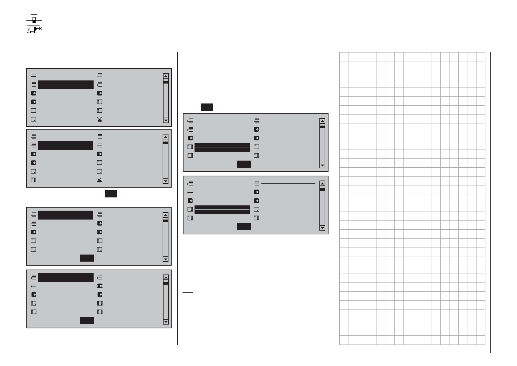
Stick mode
“MODE 1” (Throttle at right stick)
elev. down
left rudder
elev. up
“MODE 3” (Throttle at right stick) “MODE 4” (Throttle at left stick)
elev. down
left aileron
elev. up
right rudder
left aileron
right aileron
left rudder
full throttle
idle
Motor Vollgas
idle
“MODE 2” (Throttle at left stick)
full throttle
right aileron
left rudder
right rudder
left aileron
full throttle
right rudder
left aileron
idle
right aileron
left rudder
idle
elev. down
elev. up
elev. down
elev. up
There are four fundamental options for assigning
the four control functions (aileron, elevator, rudder
and throttle/brake fl ap) for a winged aircraft model
to the two joysticks. Just which of these options is
chosen depends on the individual preferences of the
individual model pilot.
Use the selection keys of the left or right touch
pad to select the "Stick mode" line. The option fi eld
will be framed.
BASIC SETTING,MODEL
Model name
Info
Stick mode
Module
HoTT
Graubele
1234g/111111
bind
n/a
1
n/a
n/a
SEL
Tap on the SET key. The currently displayed stick
mode will be displayed in inverse video. No
w use the
selection keys of the right touch pad to select from
among options 1 through 4.
A simultaneous tap on the or keys of the
right touch pad (CLEAR) will reset the display to stick
mode "1".
right aileron
right rudder
Another tap on the SET key will again deactivate
option selection so a change to another line can be
affected.
Module
BASIC SETTING,MODEL
Model name
Info
Stick mode
Module
The
mc-16 transmitter has a HoTT RF module as
standard equipment. In addition to the built-in module,
there is a connector for an external RF module
behind one of the two front cover fl aps (see page 25)
and a switchover to an external module connected
there can be affected per software. To do this, use the
selection keys of the left or right touch pad to move
the marker frame left to the "Module" selection fi eld
above the "SEL" column label.
HoTT
Graupner HoTT receivers must be "instructed"
to communicate exclusively with a certain model
(memory) in a Graupner HoTT transmitter. This
procedure is known as "binding" and must only be
done once for every new receiver/model-memorylocation combination (and can be repeated anytime).
Important notices:
During the binding procedure be sure the •
transmitter's antenna is always far enough
away from the receiver's antenna. To be on the
safe side, keep them at least one meter apart.
Otherwise there is a risk of a faulty connection to
the return channel and malfunctions will result.
When binding additional receivers, note that any •
other –switched on– receivers already bound
HoTT
SEL
Graubele
1234g/111111
bind
BD1
BD2
n/a
1
n/a
BD3
n/a
BD4
to the transmitter will fall into Fail-safe mode
during the transmitter-side "binding" period.
"Binding" multiple receivers per model
Multiple receivers per model can be bound if desired,
whereby respective
potential for managing up to four receivers directly
and for dividing up the transmitter's 16 control
channels (max) in any arrangement among these
receivers under menu control. Refer to additional
details further down in this section. First bind the
receivers individually as described below.
However, in subsequent operation only one of
these receivers will establish a telemetry bond to
the transmitter; the one which was activated in the
"TELEMETRY RCV" line of the »Telemetry« menu.
TELEMETRY
TELEMETRY RCV
SETTING & DATAVIEW
SENSOR SELECT
RF STATUS VIEW
VOICE TRIGGER
Any telemetry sensors which may be built into the
model should therefore be connected to this receiver
because the transmitter only receives and evaluates
data from the return channel of the receiver activated on
this line. The second, and all other receivers, operate in
parallel but are fully independent in slave mode.
"Binding" transmitter and receiver
Use the selection keys of the left or right touch
pad to move into the "Module" line. The marker frame
will be positioned by default to the column for the next
free binding channel. In the example shown in the
figure below, the marker frame is positioned above the
column label "BD2" because the binding channel in the
column labeled "BD1" is already in use by default for
the receiver which was delivered with the set.
mc-16 HoTT programs offer the
BIND. 1
Detail program description - Base setup models | Winged models
BASIC SETTING,MODEL
Model name
Info
Stick mode
Module
If not already off, now switch the receiver on. The red
LED on the receiv
Press and hold the
the LED contin
then, after about another 3 seconds, begins to blink
red/green. The SET
be released. As long as this LED blinks red/green, the
receiver is in bind mode.
Now, within this 3 second period, start the so-called
"receiver binding" process for the receiver to the
currently active model memory with a brief tap on the
center SET key of the right touch pad. At this time,
the screen's display will blend in a message window
for the duration of the "binding" process.
BASIC SETTING,MODEL
Model name
Info
Stick mode
Module
If the receiver's LED, again blinking red, changes
within about 10 seconds to continuous illumination
in green, the binding process has been successfully
completed. Your model-memory to receiver
combination is now operationally ready. At this time
the screen will now display " bind " (bound) instead of
"n/a" (not attached).
HoTT
SEL
er will b
SET button on the receiv
ues to b
link red for about 3 seconds
button on the receiver can now
FINDING...
HoTT
SEL
Graubele
1234g/111111
bind
BD1
link.
bind
BD1
BD2
Graubele
1234g/111111
BD2
n/a
n/a
1
n/a
BD3
1
n/a
BD3
n/a
BD4
er while
n/a
BD4
77
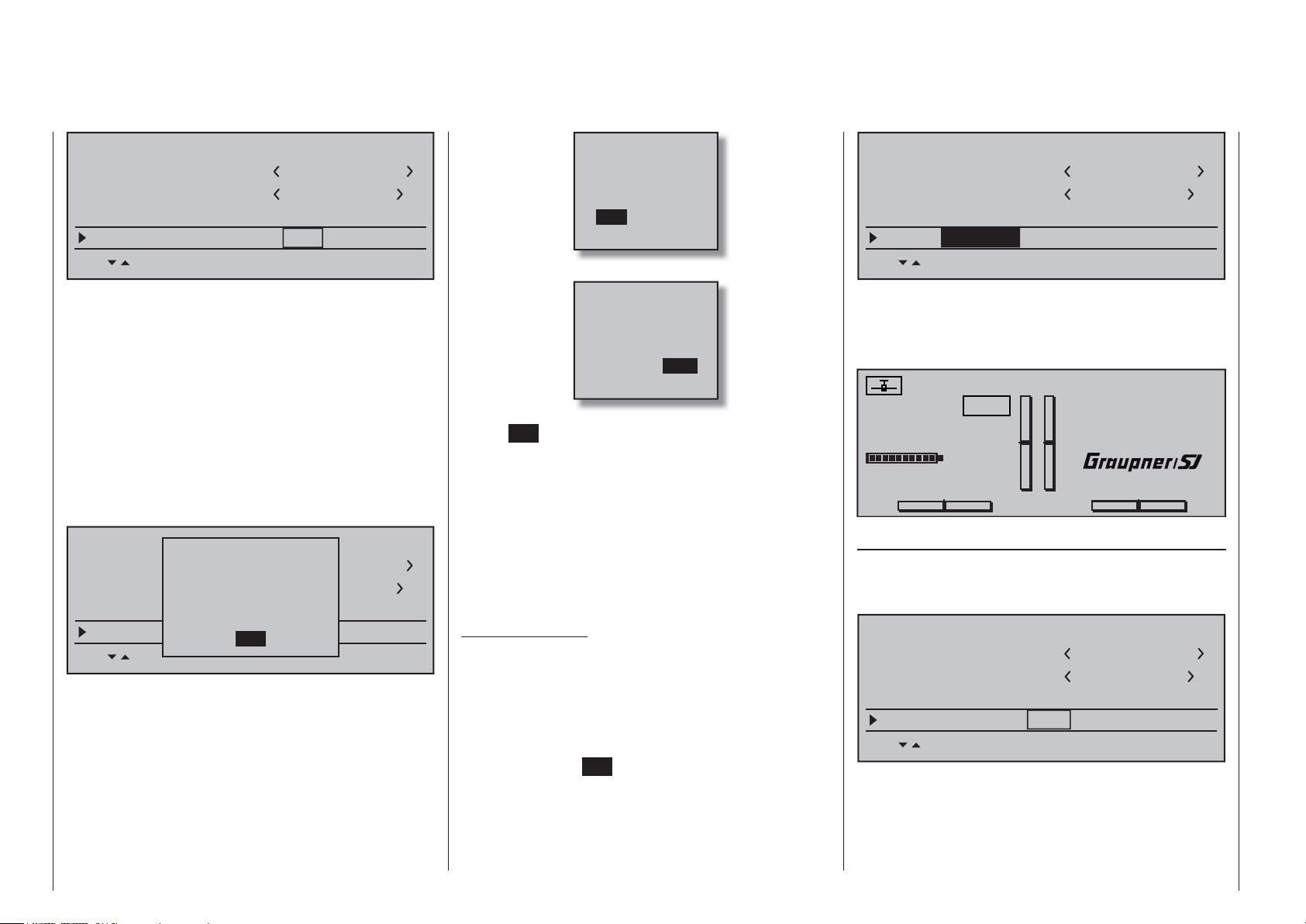
BASIC SETTING,MODEL
Model name
Info
Stick mode
Module
HoTT
SEL
Graubele
1234g/111111
bind
BD1
bind
BD2
1
n/a
BD3
n/a
BD4
… with "OFF" …
Please select
RF on/off?
OFFON
BASIC SETTING,MODEL
Model name
Info
Stick mode
Module
EXT. PPM
SEL
Graubele
1234g/111111
1
PPM10
On the other hand, should the LED on the receiver
link red f
b
binding process has f
will contin
happen, try changing the position of antennas then
repeat the entire procedure.
Binding other receivers
The binding channel you have chosen is already
bound (as indicated by the "bind" status). with
another binding channel. After initiating the RF
bind process, instead of displaying "BINDING", the
message shown below appears.
Drop down two lines in the screen and switch off the
RF module as described on the page in section "RF
module". Afterward, return again to the "Module" line
and restart the binding process as described abov
Alternatively, the transmitter can be switched off
briefl y then, after switching it back on again, respond
to the message window that appears …
78 Detail program description - Base setup models | Winged models
or longer than about 10 seconds
In this case the screen
ailed.
ue to sho
BASIC SETTING,MODEL
Model name
Info
Stick mode
Module
w the status as "n/a".
RF
is turned
off
HoTT
SEL
geb.
OK
BD1
Graubele
1234g/111111
geb.
BD2
, the
If this should
1
n/a
BD3
n/a
BD4
e.
… then confi rm the selection with a brief tap on the
center SET key of the right touch pad. From the
base screen jump again into the "Module" line of
the »Basic settings, model« menu and restart the
binding process.
Dissolving a bond
Proceed as described abo
process but WITHOUT fi rst putting a receiver in
binding readiness.
EXT. PPM
Important notice:
With the activation of the value fi eld in the context
of the following described changeover, any
existing bonds to HoTT receivers which may be
effective for the currently active model memory
will be lost.
Activate the fi rst value fi eld in the "Module" line with a
tap on the center SET key of the right touch pad then
use the selection keys to choose "EXT. PPM" instead
of "HoTT". In parallel with the selection of "EXT.
PPM", the other four value fi elds will be replaced by
the type of modulation pre-selected in the line »DSC
Output«, see page 81.
Please select
RF on/off?
ON
OFF
ve to initiate the binding
This change also suppresses the lines for the options
(described below): »HoTT«, »Rcv Ch Map«, »RF
module« and »RF range test« and, in the basic
display, "PPM" will be displayed instead of "HoTT".
Graubele
#01
H-J Sandbrunner
0:00h
PPM
00:00h
4.1V
0
Receiver channel mapping
As long as there is at least one "bound" receiver in
the "Module" line, the next line down will be the "Rcv
Ch map" line.
BASIC SETTING,MODEL
Model name
Info
Stick mode
Rcv Ch map R16 R08
As mentioned in the introduction to the "Binding
receivers" section, this menu item of the
offers both the opportunity to freely divide up the
transmitter's control channels within a receiver as well
as the opportunity to distribute the transmitter's 16
Stop watch
Flight tim
K78
V
RX VOLT:0.0v
M
0
Graubele
1234g/111111
SET SET SET SET
1
n/a
0:00.0
0:00.0
n/a
mc-16 HoTT
00
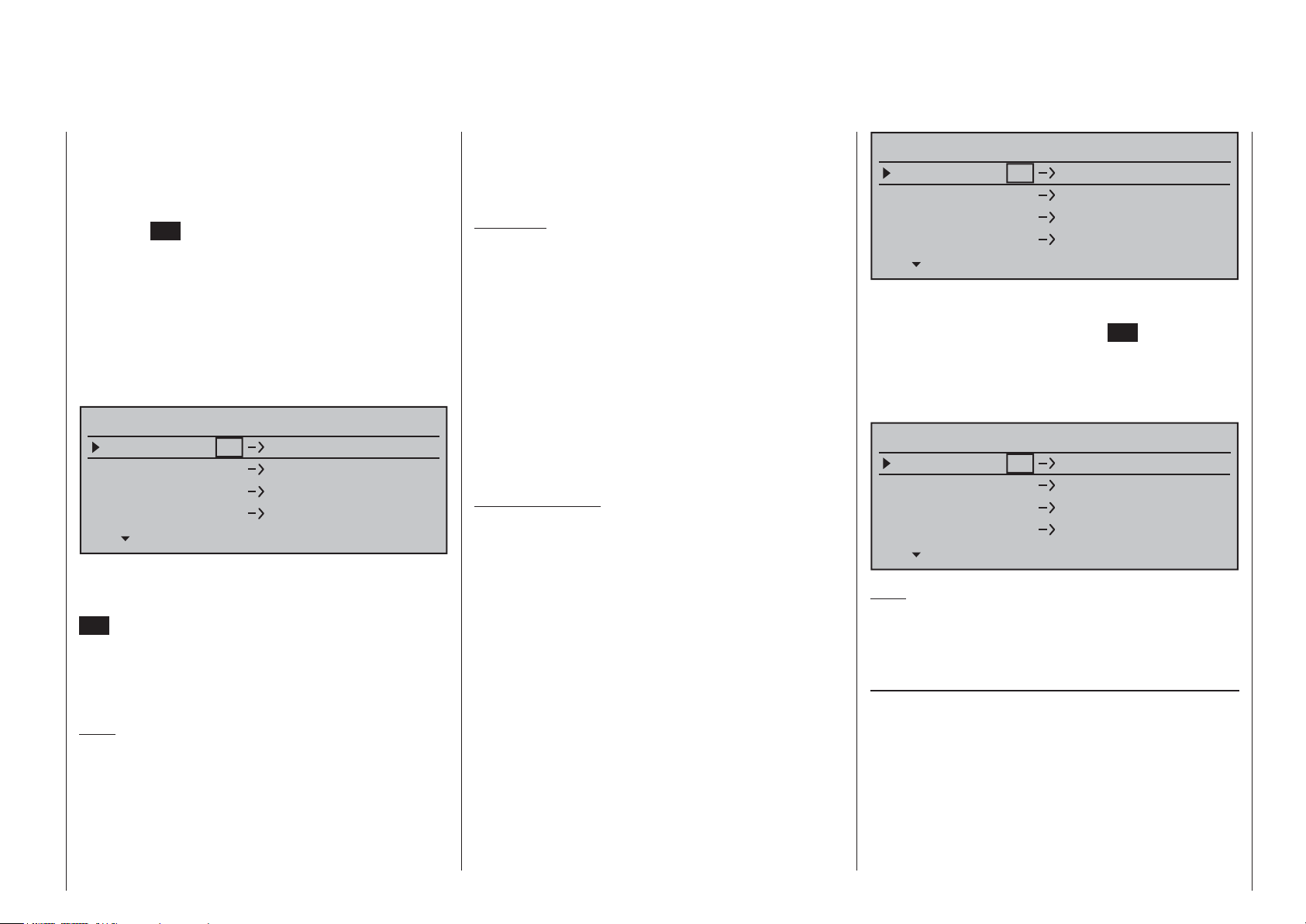
control channels across as many as four receivers.
This redistribution is subsequently referred to as
"mapping" or "channel mapping" (channel correlation).
Select the receiver to be "mapped" with the selection
keys of the left or right touch pad then tap briefl y on
the center SET key of the right touch pad.
Channel mapping within a receiver
Analogous to the channel correlation function in
the »Telemetry« menu on page 232, described as
"Channel Mapping", it is very simple to use this men
item to freely assign the transmitter's control channels
present on the receiver's inputs to any specifi c
receiver outputs (servo connections) for the bound
receiver designated by the column labeled BD1.
RECEIVER CHANNEL MAP BIND1
Rx Input Ch 1
Rx Input Ch 2
Rx Input Ch 3
Rx Input Ch 4
After selection of the desired output with the selection
keys of the left or right touch pad, the appropriate
value fi eld will be fr
SET key of the right touch pad. The current setting
will be displayed in inverse video. Now use the
selection keys of the right touch pad to select the
desired input channel's respective transmitter output,
see page 218.
Note:
The number of lines available in the list (outputs)
corresponds to the maximum number of servos which
can be attached to the given receiver.
BUT CAUTION: If, for example, "2AIL" has been
specifi ed in the "Aileron/camber fl aps" line of the
»Model type« menu then the transmitter will have
allocated control function 2 (ailerons) to control
amed. Briefl y tap on the center
Rx Output Ch 1
Rx Output Ch 2
Rx Output Ch 3
Rx Output Ch 4
u
channels 2 & 5 for the left and right ailerons. The
corresponding receiver inputs to be assigned in this
case would be channels 2 & 5, refer to the example
below.
Examples:
You would like to control each aileron of a large •
model with two or more servos.
Assign each of the appropriate outputs (servo
connections) to one and the same input (control
channel). In this case, depending on left or right
wing, as the respective input to one of the two
default aileron control channels (2 or 5).
You would like to control the rudder of a large •
model with two or more servos.
Assign each of the appropriate outputs (servo
connections) to one and the same input (control
channel). In this case, the default rudder channel
(4), see fi gure bottom right.
Important notice:
mc-16 HoTT transmitter's »Tx. output swap«
The
option permits the transmitter's 16 control functions
to be freely swapped in a similar manner or even
permits multiple outputs to be assigned to the same
control function. To keep controls manageable,
however, we strongly recommend using only one of
the options at a time.
Channel assignment on other receivers
As already mentioned, the "Rcv Ch map" menu
option can be used to freely distribute the
HoTT transmitter's 16 control channels across up
to four receivers, whereby the numbering of outputs
(servo connections) as well as the maximum number
of available lines (outputs) will correspond to the
maximum number of servo connections available on
the given receiver.
mc-16
Detail program description - Base setup models | Winged models
RECEIVER CHANNEL MAP BIND2
Rx Input Ch 16
Rx Input Ch 16
Rx Input Ch 16
Rx Input Ch 16
After selection of the desired output with the selection
keys of the left or r
fi eld will be fr
right touch pad. The current setting will be displayed
in inverse video. Now select the desired input
channel with the selection keys of the right touch pad.
For example, suitable to the above rudder example.
RECEIVER CHANNEL MAP BIND2
Rx Input Ch 4
Rx Input Ch 4
Rx Input Ch 4
Rx Input Ch 4
Note:
The number of lines available in the list (outputs)
corresponds to the maximum number of serv
can be attached to the given receiver.
RF transmit
This menu line provides an option for manually
switching the transmitter's RF transmission on and
off to specifi c models while the transmitter is in
operation. For example, to save power while a model
is being programmed. If this line option was set to
OFF, it will be canceled (i.e. set to ON) the next
time the transmitter is switched on.
If necessary, use the selection keys of the left or
right touch pad to move into the " RF transmit " line
ight touch pad, the respectiv
amed.
Tap the center SET key of the
Rx Output Ch 1
Rx Output Ch 2
Rx Output Ch 3
Rx Output Ch 4
e input
Rx Output Ch 1
Rx Output Ch 2
Rx Output Ch 3
Rx Output Ch 4
os which
79
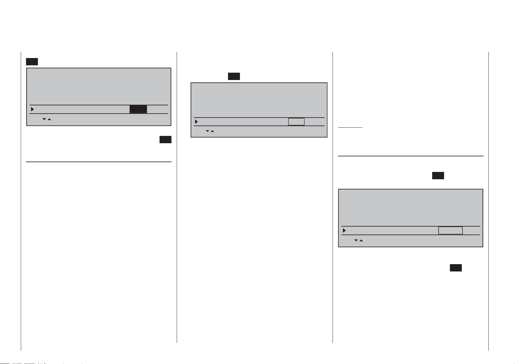
then activate the option with a brief tap on the center
SET button of the right touch pad.
BASIC SETTING,MODEL
Stick mode
Module
HoTT
bind
bind
Rcv Ch Map R16 R08
1
n/a
n/a
n/a
n/a
RF transmit on
SET SET SEL SET
The right selection keys can now be used to choose
between OFF and ON. Another tap on the center
SET
key of the right touch pad will conclude the entry.
Range test
The built-in range test reduces transmission power
to an extent that a functional test can be carried out
even within a distance of less than 100 m.
Perform a range test on the Graupner HoTT system
according to the following instructions. If necessary,
have someone assist you in carrying out the range test.
Preferably, the receiver already bound to the 1.
transmitter should be installed into the model in its
intended position.
Switch remote control on and wait for the green 2.
LED to light up on the receiver/s. Now servo
movements can be observed.
Place the model on a level surface (pavement, 3.
low-cut grass or bare ground) such that receiver
antennas are at least 15 cm above ground level.
It may be necessary to put something under the
model to raise it up enough for this.
Hold the transmitter at hip level and at some 4.
distance from one's body. Do not point the
antenna directly at the model but rather turn and/
or kink the antenna's end so that it is oriented
vertically during the test.
If necessary, use the 5. selection keys of the left
or right touch pad to reach the "RF range test" line
in the menu then start range test mode with a tap
on the center SET key of the right touch pad.
BASIC SETTING,MODELL
Module
Rcv Ch Map R16 R08
RF transmit on
RF range test 99s
HoTT
bind
bind
SET SET SEL SET
n/a
n/a
n/a
n/a
When the range test has been initiated,
the transmitter's transmission power will be
signifi cantly reduced and the LED just to the right
of the main switch on the transmitter, marked RF,
will begin to blink; this will also be accompanied by
acoustic tones. At the same time, the timer in the
transmitter's display will start counting down and
every 5 seconds a two-frequency tone will sound.
Five seconds prior to the end of the range test
a three-frequency tone will sound once every
second. After expiration of the range test's 99th
second the transmitter will again be switched to
full output power and the LED just to the right
of the main switch on the transmitter will again
illuminate constantly.
Move away from the model while manipulating 6.
the joysticks during this timespan. If you notice an
interruption anytime while still within a distance of
about 50 m, try to reproduce this malfunction.
If there is a motor in the model, it may be necessary 7.
to switch it on to further check noise immunity.
Continue moving away from the model until 8.
perfect control is no longer possible.
Wait at this distance for the remainder of the test 9.
period with the still-operationally-ready model
to expire. After the range test is ended it should
again respond correctly to all RC controls. If this
is not 100 % the case, do not use the system.
Contact your area's Graupner GmbH & Co. KG
service partner.
Perform the range test before each fl ight and, in 10.
doing so, simulate all servo movements which
also take place during fl ight. The range must
always be at 50 m on the ground in order to
assure safe model operation.
Caution:
Never start the range test on the transmitter
during normal operation of the model.
DSC output
If necessary, use the selection keys of the left
or right touch pad to switch to the "DSC Output" line
then, with a brief tap on the center SET key of the
right touch pad, activate the value window:
BASIC SETTING,MODEL
Rcv Ch Map R16 R08
n/a
n/a
RF transmit on
RF range test 99s
DSC Output PPM10
SET SET SEL SET
Now you can use the right selection keys to choose
between four types of modulation "PPM10", "PPM16",
"PPM18" and "PPM24". Touch the center SET
key of
the right touch pad again to complete the entry.
This choice primarily infl uences the maximum
number of control channels which can be attached to
the DSC (direct servo control) socket, and thus also
available to a fl ight simulator or teacher/pupil system.
By selecting "PPM10" this will be control channels
1 … 5, for "PPM16" channels 1 … 8, for "PPM18"
channels 1 … 9 and for "PPM24" channels 1 … 12.
80 Detail program description - Base setup models | Winged models
 Loading...