

Page 1
GRAUPNER GmbH & Co. KG D-73230 KIRCHHEIM/TECK GERMANY
Änderungen vorbehalten! Keine Haftung für Druckfehler Ident. # 0059200 10.2008
1
zu Best.-Nr. 9449
Anleitung
VENTUS 2 cx
Segelflugmodell
Für
Hangflug und F-Schlepp
Es wird eine Fernsteuerung mit mind. 8 Funktionen benötigt !
Page 2

GRAUPNER GmbH & Co. KG D-73230 KIRCHHEIM/TECK GERMANY
Änderungen vorbehalten! Keine Haftung für Druckfehler Ident. # 0059200 10.2008
2
Technische Daten
Spannweite ca. 5500 mm
Rumpflänge ca. 1970 mm
Tragflügelprofil HQ/W 3/13
Höhenleitwerksprofil HQ/W 0/10
Tragflächeninhalt ca. 104 dm²
Höhenleitwerksinhalt ca. 9,4 dm²
Gesamtflächeninhalt ca. 113,4 dm²
Fluggewicht je nach
Ausrüstung ab ca. 9500 g
Schwerpunkt ca. 107 - 111 mm hinter der Nasenleiste rechts und links
neben dem Rumpf gemessen.
EWD ca. 1 – 1,5 °
Vor dem Versuch der ersten Inbetriebnahme muss die gesamte Betriebs- und
Montageanleitung sorgfältig gelesen werden. Sie alleine sind verantwortlich für
den sicheren Betrieb Ihres RC-Flugmodells. Bei Jugendlichen muss der Bau
und Betrieb von einem Erwachsenen, der mit den Gegebenheiten und
möglichen Gefahren eines RC-Flugmodells vertraut ist, verantwortlich
überwacht werden.
Fragen, die die Sicherheit beim Betrieb des RC-Flugmodells betreffen, werden
Ihnen vom Fachhandel gerne beantwortet.
Fernsteuer-Flugmodelle sind sehr anspruchsvolle und gefährliche
Gegenstände und erfordern vom Betreiber einen hohen Sachverstand, Können
und Verantwortungsbewusstsein.
Rechtlich gesehen, ist ein Flugmodell ein Luftfahrzeug und unterliegt
entsprechenden Gesetzen, die unbedingt eingehalten werden müssen. Die
Broschüre »Modellflugrecht, Paragrafen und mehr«, Best.-Nr 8034.02 stellt eine
Zusammenfassung dieser Gesetze dar; sie kann auch beim Fachhandel
eingesehen werden. Ferner müssen postalische Auflagen, die die
Fernlenkanlage betreffen, beachtet werden. Entsprechende Hinweise finden Sie
in der Bedienungsanleitung Ihrer Fernsteueranlage.
Es dürfen nur die dem Bausatz enthaltenen Teile, sowie die ausdrücklich von
uns empfohlenen Original Graupner-Zubehör- und Ersatzteile verwendet
werden. Wird auch nur eine Komponente der Antriebseinheit geändert, ist ein
sicherer Betrieb nicht mehr gewährleistet und es erlischt jeglicher etwaiger
Garantieanspruch.
Verwenden Sie immer nur passende, verpolungssichere Steckverbindungen.
Kurzschlüsse und Falschpolungen vermeiden.
Durch die hohe Energie der NiMH-Batterien besteht Explosions- und
Brandgefahr.
Ein RC-Flugmodell kann nur funktionsfähig sein und den Erwartungen
entsprechen, wenn es im Sinne der Bauanleitung sorgfältigst gebaut wurde.
Nur ein vorsichtiger und überlegter Umgang beim Betrieb schützt vor
Page 3
GRAUPNER GmbH & Co. KG D-73230 KIRCHHEIM/TECK GERMANY
Änderungen vorbehalten! Keine Haftung für Druckfehler Ident. # 0059200 10.2008
3
Personen- und Sachschäden. Niemand würde sich in ein Segelflugzeug setzen
und - ohne vorausgegangene Schulung - versuchen, damit zu fliegen. Auch
Modellfliegen will gelernt sein.
Der Hersteller hat jedoch keine Möglichkeit den Bau und den Betrieb eines RCFlugmodells zu beeinflussen. Deshalb wird hiermit auf die Gefahren
nachdrücklich hingewiesen und jede Haftung dafür abgelehnt.
Bitte wenden Sie sich dazu an erfahrene Modellflieger, an Vereine oder
Modellflugschulen. Ferner sei auf den Fachhandel und die einschlägige
Fachpresse verwiesen. Am besten als Club-Mitglied auf zugelassenem
Modellflugplatz fliegen.
Klebstoffe und Lacke enthalten Lösungsmittel, die unter Umständen
gesundheitsschädlich sein können. Beachten Sie daher unbedingt auch die
entsprechenden Hinweise und Warnungen der Hersteller.
Der Betreiber muss im Besitz seiner vollen körperlichen und geistigen
Fähigkeiten sein. Wie beim Autofahren, ist der Betrieb des Flugmodells unter
Alkohol oder Drogeneinwirkung nicht erlaubt.
Informieren Sie alle Passanten und Zuschauer vor der Inbetriebnahme über alle
möglichen Gefahren, die von Ihrem Modell ausgehen können.
Stets mit dem notwendigen Sicherheitsabstand zu Personen oder
Gegenständen fliegen; nie Personen in niedriger Höhe überfliegen oder auf sie
zufliegen!
Modellflug darf nur bei Außentemperaturen von- 5º C bis + 35º C betrieben
werden. Extremere Temperaturen können zu Veränderungen von z. B. AkkuKapazität, Werkstoffeigenschaften und mangelhafte Klebeverbindungen
führen.
Jeder Modellflieger hat sich so zu verhalten, dass die öffentliche Sicherheit
und Ordnung, insbesondere andere Personen und Sachen, sowie die Ordnung
des Modellflugbetriebs nicht gefährdet oder gestört wird.
Das Flugmodell niemals in der Nähe von Hochspannungsleitungen,
Industriegelände, in Wohngebieten, öffentlichen Straßen, Plätzen, Schulhöfen,
Parks und Spielplätzen usw. fliegen lassen.
Warnungen müssen unbedingt beachtet werden. Sie beziehen sich auf Dinge
und Vorgänge, die bei einer Nichtbeachtung zu schweren - in Extremfällen
tödlichen Verletzungen oder bleibenden Schäden führen können.
Überprüfen Sie vor jeder Inbetriebnahme das Modell und alle an ihm
gekoppelten Teile (z. B. RC-Teile, Ruderhörner usw.) auf festen Sitz und
Page 4

GRAUPNER GmbH & Co. KG D-73230 KIRCHHEIM/TECK GERMANY
Änderungen vorbehalten! Keine Haftung für Druckfehler Ident. # 0059200 10.2008
4
mögliche Beschädigungen. Das Modell darf erst nach Beseitigung aller
Mängel in Betrieb genommen werden.
Auf gute Standfestigkeit achten, wenn Sie das Modell in der Hand halten.
Passendes Schuhwerk, z. B. Sportschuhe tragen.
Vergewissern Sie sich, dass die verwendete Frequenz frei ist. Erst dann
einschalten! Funkstörungen, verursacht durch Unbekannte, können stets
ohne Vorwarnung auftreten! Das Modell ist dann steuerlos und
unberechenbar! Fernlenkanlage nicht unbeaufsichtigt lassen, um ein
Betätigen durch Dritte zu verhindern.
Die Fluglage des Modells muss während des gesamten Fluges immer
eindeutig erkennbar sein, um immer ein sicheres Steuern und Ausweichen zu
gewährleisten. Machen sich während des Fluges Funktionsbeeinträchtigungen/Störungen bemerkbar, muss aus Sicherheitsgründen sofort die
Landung eingeleitet werden. Sie haben anderen Luftfahrzeugen stets
auszuweichen. Start- und Landeflächen müssen frei von Personen und
sonstigen Hindernissen sein.
Immer auf vollgeladene Akkus achten, da sonst keine einwandfreie Funktion
der RC-Anlage gewährleistet ist.
Niemals heiß gewordene, defekte oder beschädigte Batterien verwenden. Es
sind stets die Gebrauchsvorschriften des Batterieherstellers zu beachten.
Vor jedem Flug eine Überprüfung der kompletten RC-Anlage, sowie des
Flugmodells, auf volle Funktionstüchtigkeit und Reichweite durchführen.
Zuerst den Sender und dann erst die Empfangsanlage einschalten. Gleichfalls
gilt immer zuerst Empfangsanlage ausschalten, danach erst den Sender.
Überprüfen Sie, dass die Ruder sich entsprechend der Steuerknüppelbetätigung bewegen.
Nach Gebrauch alle Batterien aus dem Modell nehmen und nur im entladenen
Zustand (ca. 0,9 V pro Zelle) für Kinder unzugänglich, bei ca. + 5º bis + 25º C
aufbewahren.
Mit diesen Hinweisen soll auf die vielfältigen Gefahren hingewiesen werden,
die durch unsachgemäße und verantwortungslose Handhabung entstehen
können. Richtig und gewissenhaft betrieben ist Modellflug eine kreative,
lehrreiche und erholsame Freizeitgestaltung.
Hinweise zur Benutzung von NiMH-Batterien
Anwendungsbereich
Alle Graupner NiMH-Batterien sowie NiMH-Einzelzellen sind ausschließlich für den
modellbautypischen Einsatzzweck in Flug-, Schiffs- oder Automodellen geeignet.
Page 5

GRAUPNER GmbH & Co. KG D-73230 KIRCHHEIM/TECK GERMANY
Änderungen vorbehalten! Keine Haftung für Druckfehler Ident. # 0059200 10.2008
5
Laden
1. Die NiMH-Batterie mit einem geeigneten Ladegerät bzw. Schnellladegerät laden
(siehe Ladegeräte im Graupner-Hauptkatalog FS).
2. Vor der Ladung muss die Batterie auf eine Temperatur von ca. 20° C abgekühlt
sein. Die Batterie erst unmittelbar vor dem Einsatz laden. Jede NiMH-Batterie
unterliegt, technisch bedingt, einer geringen Selbstentladung.
3. Warnung:
Der Ladevorgang muss auch bei vollautomatischen Ladegeräten überwacht
werden. Den jeweils auf der Batterie bzw. Einzelzelle angegebenen maximal
zulässigen Ladestrom beachten. Ein zu hoher Ladestrom führt zur Überhitzung
der NiMH-Zellen. Erwärmt sich die Batterie während des Ladevorganges auf ca.
50° C, muss der Ladestrom sofort unterbrochen werden. Durch Überhitzung der
NiMH-Zellen steigt der Überdruck im Zellengehäuse stark an. Jede einzelne
NiMH-Zelle einer Batterie ist mit einem Überdruckventil ausgerüstet, das im
Notfall die Zelle vor einer gefährlichen Explosion schützt. Durch unvorhersehbare
Umstände kann jedoch ein Ventil nicht mehr vorschriftsmäßig funktionieren, so
dass eine Explosion bei übermäßiger Erhitzung der Zelle möglich ist.
4. Warnung:
Versehentlich überladene NiMH-Batterien nicht berühren, sondern den
Ladestrom unterbrechen und die Batterie abkühlen lassen.
5. Warnung:
Kurzschlüsse unbedingt vermeiden, da sich bei extremer Schnellentladung, was
bei einem Kurzschluss vorliegt, die Batterie sofort stark erhitzt, was genau wie
das Überladen eine Zellenexplosion hervorrufen kann → Verletzungsgefahr durch
Explosion und Ätzungsgefahr durch Elektrolyt in der Zelle.
Ausgelaufenes Elektrolyt nicht mit der Hand oder den Augen in Berührung
bringen. Sofern dies im Notfall passiert, sofort mit reichlich Wasser spülen und
einen Arzt aufsuchen.
7. Niemals direkt auf dem Zellengehäuse Kabel oder ähnliches anlöten, da unter
Umständen das Überdruckventil beschädigt wird.
8 Warnung:
Defekte oder alte NiMH-Batterien niemals ins Feuer werfen → Explosionsgefahr.
Keinesfalls in die Mülltonne werfen, sondern in die dafür vorgesehenen
Sammelcontainer. Dies kostet Sie nichts und sorgt für eine saubere Umwelt, da
die Batterie zum größten Teil recyclingfähig ist.
Hinweise zum Bau und Flugbetrieb
Bevor mit dem Bau begonnen wird:
RC-Teile sowie Rudergestänge werden während des Zusammenbaus nach den
entsprechenden Baustufen eingebaut. Ein späterer Einbau ist gar nicht - oder nur
sehr schwierig möglich.
Achten Sie beim Kauf einer Funkfernsteuerung darauf, dass die Sende- und
Empfangsgeräte auch für Flugmodelle geeignet und bei der Deutschen
Bundespost-Telekom zugelassen sind, sowie eine FTZ-Serienprüfnummer besitzen.
In den Frequenzbereichen für Funkfernsteuerungen werden auch andere
Funkanlagen und Hochfrequenzgeräte betrieben. Deshalb kann kein Schutz vor
Störungen durch solche Geräte gewährt werden.
Page 6

GRAUPNER GmbH & Co. KG D-73230 KIRCHHEIM/TECK GERMANY
Änderungen vorbehalten! Keine Haftung für Druckfehler Ident. # 0059200 10.2008
6
Weitere Information zu diesem Thema bekommen Sie bei Ihrer örtlichen TelekomNiederlassung oder bei Ihrem Modellbau-Fachhändler.
Während der Bauphase
Beachten Sie beim Umgang mit Klebstoffen und Lösungsmitteln die Sicherheits- und
Verarbeitungshinweise der Hersteller. Manche Klebstoffe und Lösungsmittel können
Gesundheits- und Materialschäden verursachen, wenn sie nicht fachgerecht
angewendet werden. Geben Sie Klebstoff- und Farbreste im Fachhandel oder bei
Sondermüllsammelstellen ab.
Achten Sie darauf, dass Balsamesser scharf und Stecknadeln spitz sind und somit
leicht zu Verletzungen führen können.
Achten Sie darauf, dass Kinder keinen Zugang zu Werkzeugen, Klebstoffen oder
Lacken haben.
Eine großzügig bemessene freie Arbeitsfläche ist bei allen Bastelarbeiten von
besonderem Vorteil.
Lassen Sie sich schwierige Arbeitsgänge von erfahrenen Modellbauern
zeigen, wenn Sie noch wenig Erfahrung im Modellbau haben.
Zum Flugbetrieb
Lassen Sie den VENTUS 2 cx niemals in Naturschutz- oder
Landschaftsschutzgebieten fliegen. Nehmen Sie Rücksicht auf die dort lebenden
Tiere und Pflanzen.
Bäume und Sträucher dienen als Kinderstube, Nest und Lebensraum von Vögeln.
Wichtige Sicherheitshinweise
Sie haben einen Bausatz erworben, aus dem – zusammen mit entsprechendem
geeigneten Zubehör – ein funktionsfähiges RC-Modell fertiggestellt werden kann. Die
Einhaltung der Montage- und Betriebsanleitung im Zusammenhang mit dem Modell
sowie die Installation, der Betrieb, die Verwendung und Wartung der mit dem Modell
zusammenhängenden Komponenten können von GRAUPNER nicht überwacht
werden. Daher übernimmt GRAUPNER keinerlei Haftung für Verluste, Schäden oder
Kosten, die sich aus dem fehlerhaften Betrieb, aus fehlerhaftem Verhalten bzw. in
irgendeiner Weise mit dem vorgenannten zusammenhängend ergeben. Soweit vom
Gesetzgeber nicht zwingend vorgeschrieben, ist die Verpflichtung der Firma
GRAUPNER zur Leistung von Schadensersatz, aus welchem Grund auch immer
ausgeschlossen (inkl. Personenschäden, Tod, Beschädigung von Gebäuden sowie
auch Schäden durch Umsatz- oder Geschäftsverlust, durch Geschäftsunterbrechung
oder andere indirekte oder direkte Folgeschäden), die von dem Einsatz des Modells
herrühren.
Die Gesamthaftung ist unter allen Umständen und in jedem Fall beschränkt auf den
Betrag, den Sie tatsächlich für dieses Modell gezahlt haben.
Die Inbetriebnahme und der Betrieb des Modells erfolgt einzig und allein auf Gefahr
des Betreibers. Nur ein vorsichtiger und überlegter Umgang beim Betrieb schützt vor
Personen- und Sachschäden.
Schließen Sie gegebenenfalls eine spezielle RC-Modell-Haftpflichtversicherung
ab.
Page 7

GRAUPNER GmbH & Co. KG D-73230 KIRCHHEIM/TECK GERMANY
Änderungen vorbehalten! Keine Haftung für Druckfehler Ident. # 0059200 10.2008
7
Diese Sicherheitshinweise müssen unbedingt aufbewahrt werden und müssen
bei einem Weiterverkauf des Modells an den Käufer weitergegeben werden.
Herstellererklärung:
Sollten sich Mängel an Material oder Verarbeitung an einem von uns in der
Bundesrepublik Deutschland vertriebenen, durch einen Verbraucher (§ 13 BGB)
erworbenen Gegenstand zeigen, übernehmen wir, die Fa. Graupner GmbH & Co KG,
D 73230 Kirchheim/Teck im nachstehenden Umfang die Mängelbeseitigung für den
Gegenstand.
Rechte aus dieser Herstellererklärung kann der Verbraucher nicht geltend machen,
wenn die Beeinträchtigung der Brauchbarkeit des Gegenstandes auf natürlicher
Abnutzung, Einsatz unter Wettbewerbsbedingungen, unsachgemäßer Verwendung
(einschließlich Einbau) oder Einwirkung von außen beruht.
Diese Herstellererklärung lässt die gesetzlichen oder vertraglich eingeräumten
Mängelansprüche und –rechte des Verbrauchers aus dem Kaufvertrag gegenüber
seinem Verkäufer (Händler) unberührt.
Umfang der Garantieleistung
Im Garantiefall leisten wir nach unserer Wahl Reparatur oder Ersatz der
mangelbehafteten Ware. Weitergehende Ansprüche, insbesondere Ansprüche auf
Erstattung von Kosten im Zusammenhang mit dem Mangel (z.B. Ein-/Ausbaukosten)
und der Ersatz von Folgeschäden sind – soweit gesetzlich zugelassen –
ausgeschlossen. Ansprüche aus gesetzlichen Regelungen, insbesondere nach dem
Produkthaftungsgesetz, werden hierdurch nicht berührt.
Voraussetzung der Garantieleistung
Der Käufer hat den Garantieanspruch schriftlich unter Beifügung des Originals des
Kaufbelegs (z.B. Rechnung, Quittung, Lieferschein) und dieser Garantiekarte geltend
zu machen. Er hat zudem die defekte Ware auf seine Kosten an die o.g. Adresse
einzusenden
Der Käufer soll dabei den Material- oder Verarbeitungsfehler oder die Symptome des
Fehlers so konkret benennen, dass eine Überprüfung unserer Garantiepflicht möglich
wird.
Der Transport des Gegenstandes vom Verbraucher zu uns als auch der
Rücktransport erfolgen auf Gefahr des Verbrauchers.
Gültigkeitsdauer
Diese Erklärung ist nur für während der Anspruchsfrist bei uns geltend gemachten
Ansprüche aus dieser Erklärung gültig. Die Anspruchsfrist beträgt 24 Monate ab Kauf
des Gerätes durch den Verbraucher bei einem Händler in der Bundesrepublik
Deutschland (Kaufdatum). Werden Mängel nach Ablauf der Anspruchsfrist angezeigt
oder die zur Geltendmachung von Mängeln nach dieser Erklärung geforderten
Nachweise oder Dokumente erst nach Ablauf der Anspruchsfrist vorgelegt, so stehen
dem Käufer keine Rechte oder Ansprüche aus dieser Erklärung zu.
Page 8

GRAUPNER GmbH & Co. KG D-73230 KIRCHHEIM/TECK GERMANY
Änderungen vorbehalten! Keine Haftung für Druckfehler Ident. # 0059200 10.2008
8
Verjährung
Soweit wir einen innerhalb der Anspruchsfrist ordnungsgemäß geltend gemachten
Anspruch aus dieser Erklärung nicht anerkennen, verjähren sämtliche Ansprüche aus
dieser Erklärung in 6 Monaten vom Zeitpunkt der Geltendmachung an, jedoch nicht
vor Ende der Anspruchsfrist.
Anwendbares Recht
Auf diese Erklärung und die sich daraus ergebenden Ansprüche, Rechte und
Pflichten findet ausschließlich das materielle deutsche Recht ohne die Normen des
Internationalen Privatrechts sowie unter Ausschluss des UN-Kaufrechts Anwendung.
Folgende Punkte müssen unbedingt beachtet werden:
• Kontrollieren Sie, bevor Sie das Modell starten, dieses auf eine sichere Funktion
der Fernsteuerung sowie die Steckverbindungen auf sichere und feste
Verbindung.
• Die Akkus müssen geladen sein und die Reichweite der Fernsteuerung muss
überprüft worden sein. Besonders die Sender- und Empfängerakkus müssen vor
jedem Start geladen werden.
• Prüfen Sie, ob der von Ihnen genutzte Kanal frei ist. Fliegen Sie niemals, wenn
Sie sich nicht sicher sind, ob der Kanal frei ist.
• Beachten Sie die Empfehlungen und Hinweise zu Ihrer Fernsteuerung und
Zubehörteilen.
• Achten Sie darauf, dass die Servos in ihrem Verfahrweg mechanisch nicht
begrenzt werden.
• Batterien und Akkus dürfen nicht kurzgeschlossen werden.
• Entnehmen Sie die Akkus bei Transport und Nichtgebrauch des Modells.
• Setzen Sie das Modell nicht starker Luftfeuchtigkeit, Hitze, Kälte sowie Schmutz
aus.
• Sichern Sie das Modell und RC-Komponenten beim Transport gegen
Beschädigung sowie Verrutschen.
• WICHTIG: Der im Modell eingebaute Akku darf nicht im Hausmüll entsorgt
werden. Der Akku muss in Altbatterierücknahmebehältern entsorgt werden.
WICHTIG: Das Modell und der Sender dürfen nicht im Hausmüll entsorgt werden
und müssen auf einem Wertstoffhof als Elektroschrott abgegeben werden.
Erkundigen Sie sich hierzu bei Ihrer Gemeinde.
•
Überprüfung vor dem Start
Vor jedem Einsatz korrekte Funktion und Reichweite überprüfen. Dazu den Sender
einschalten, ebenso den Empfänger. Senderantenne einschrauben und auf
vollständige Länge ausziehen. Aus entsprechendem Abstand vom Modell
kontrollieren, ob alle Ruder einwandfrei funktionieren und in der richtigen Richtung
ausschlagen.
Beim erstmaligen Steuern eines Flugmodells ist es von Vorteil, wenn ein erfahrener
Helfer bei der Überprüfung und den ersten Flügen zur Seite steht.
Page 9

GRAUPNER GmbH & Co. KG D-73230 KIRCHHEIM/TECK GERMANY
Änderungen vorbehalten! Keine Haftung für Druckfehler Ident. # 0059200 10.2008
9
Pflege und Wartung
• Säubern Sie das Modell nach jedem Gebrauch. Reinigen Sie das Modell und die
RC-Komponenten nur mit geeigneten Reinigungsmitteln. Informieren Sie sich
hierzu bei Ihrem Fachhändler.
Hinweise zum Bau des Modells
Vor dem Bau des Modells sollte man unbedingt die Anleitung bis zum Schluss
studieren. Achten Sie beim Einsatz von Werkzeugen auf die möglichen Gefahren.
Notwendiges Werkzeug zum Bau von VENTUS 2 cx
Bleistift (Minenhärte HB), All-Stift, Geometriedreieck sowie Bandmaß oder
Meterstab, Haushaltsschere, schmales scharfes Messer, z. B. Balsa-Messer Best.Nr. 980, elektrische Kleinbohrmaschine, verschiedene Spiralbohrer, SechskantStiftschlüssel, Injektionsspritze Best.-Nr. 739.3.
Verkleben von Materialien
Die nachfolgende Tabelle gibt einige Beispiele für Klebeverbindungen.
Sie hat keinen Anspruch auf Vollständigkeit.
Werkstoff Verklebbeispiel Klebstoff
Best.-Nr. .
GFK mit Tragflügel mit UHU plus endfest 300
Sperrholz Servobrettchen Best.-Nr. 950.43
GFK mit Rumpf mit UHU plus endfest 300
Aluminium F-Schleppkupplung Best.-Nr. 950.43
GFK mit Instrumentenpilz mit UHU plus schnellfest
Sperrholz Instrumentenbrett Best.-Nr. 962
Die zu verklebenden Stellen im Rumpf und Tragflügelteilen mit Sandpapier feiner
Körnung anschleifen, um anhaftendes Trennmittel zu entfernen. Schleifstaub
Page 10
GRAUPNER GmbH & Co. KG D-73230 KIRCHHEIM/TECK GERMANY
Änderungen vorbehalten! Keine Haftung für Druckfehler Ident. # 0059200 10.2008
10
abwischen. In jedem Falle muss die glänzende Oberfläche im Rumpf matt werden,
da sonst keine gute Verbindung des Klebstoffes mit dem Rumpf gewährleistet ist.
Zur Verbindung der einzelnen Teile untereinander sind die entsprechenden
Verarbeitungsvorschriften der Klebstoffe zu beachten. Weitere Klebstoffe sind im
Katalog FS zu finden.
Sorgen Sie bei Klebstoffen mit Lösungsmitteln für einen gut belüfteten Raum.
Beachten Sie die Hinweise des Herstellers.
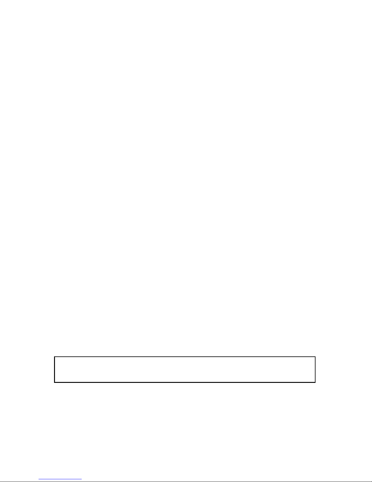
Fernlenkanlage
Besonders empfohlen: Computer-System ab mc-19S, mc-22S, mc-24,mx-22, mx-24
Empfohlene Servos:
Seitenruder DS 8077 Best.-Nr. 5149 1 Stück
Höhenruder DS 3068 Best.-Nr. 5188 1 Stück
Querruder DS 3068 Best.-Nr. 5188 2 Stück
Mittlere Wölbklappe DS 3328 Best.-Nr. 5157 2 Stück
Innere Wölbklappe DS 3328 Best.-Nr. 5157 2 Stück
Landeklappen DS 3068 Best.-Nr. 5188 2 Stück
F-Schleppkupplung DS 8077 Best.-Nr. 5149 1 Stück
Radbremse DS 8077 Best.-Nr. 5149 1 Stück
Als Empfänger wird ein DS 24 FM 35 S benötigt.
Best.-Nr. 3050 Power-Schalterkabel 1 Stück
Benötigte Servoverlängerungskabel
Best.-Nr. 3935.105 für Querruder 2 Stück
Best.-Nr. 3935.18 für Anschluss am Empfänger 2 Stück
Best.-Nr. 3935.11 für Anschluss am Empfänger 2 Stück
Page 11
GRAUPNER GmbH & Co. KG D-73230 KIRCHHEIM/TECK GERMANY
Änderungen vorbehalten! Keine Haftung für Druckfehler Ident. # 0059200 10.2008
11
Best.-Nr. 3935.50 für Anschluss am Empfänger 1 Stück
Best.-Nr. 3935.180 für Höhenruder 1 Stück
Best.-Nr.98516.1 Klapp-Ferritkern für Querruder und
Landeklappenservos 1 Stück
Best.-Nr. 1587 Klett-Kabelbinder 1 Packung
Als Empfängerakku empfehlen wir einen Akku mit einer Kapazität von mindestens
3 Ah z.B.Best.-Nr.2490.4 welcher vor und nach dem Flugbetrieb stets gut gewartet
werden muss, d. h., bis zum Erreichen der angegebenen Kapazität muss der Akku
mehrmals entladen und wieder geladen werden.
Es werden absichtlich wiederaufladbare Batterien für den Empfänger und Sender
empfohlen, da die Sicherheit hierbei am größten ist.
Die entsprechenden Ladegeräte dazu siehe Katalog FS.
Schaumgummi zur Lagerung vom Empfänger
Zusammenbau des VENTUS 2 cx
Beginnen Sie erst mit dem Zusammenbau, wenn Sie sich mit den Bauteilen und
einzelnen Baustadien vertraut gemacht haben. Sollte ein Bauteil Grund zur
Beanstandung geben, so ist dies vor Baubeginn Ihrem Fachhändler mitzuteilen.
Der Rumpf
Sämtliche Klebestellen im Rumpf müssen mit Schleifpapier angeschliffen werden, bis
die Klebestelle matt wird (siehe auch Hinweis nach der Klebstofftabelle).
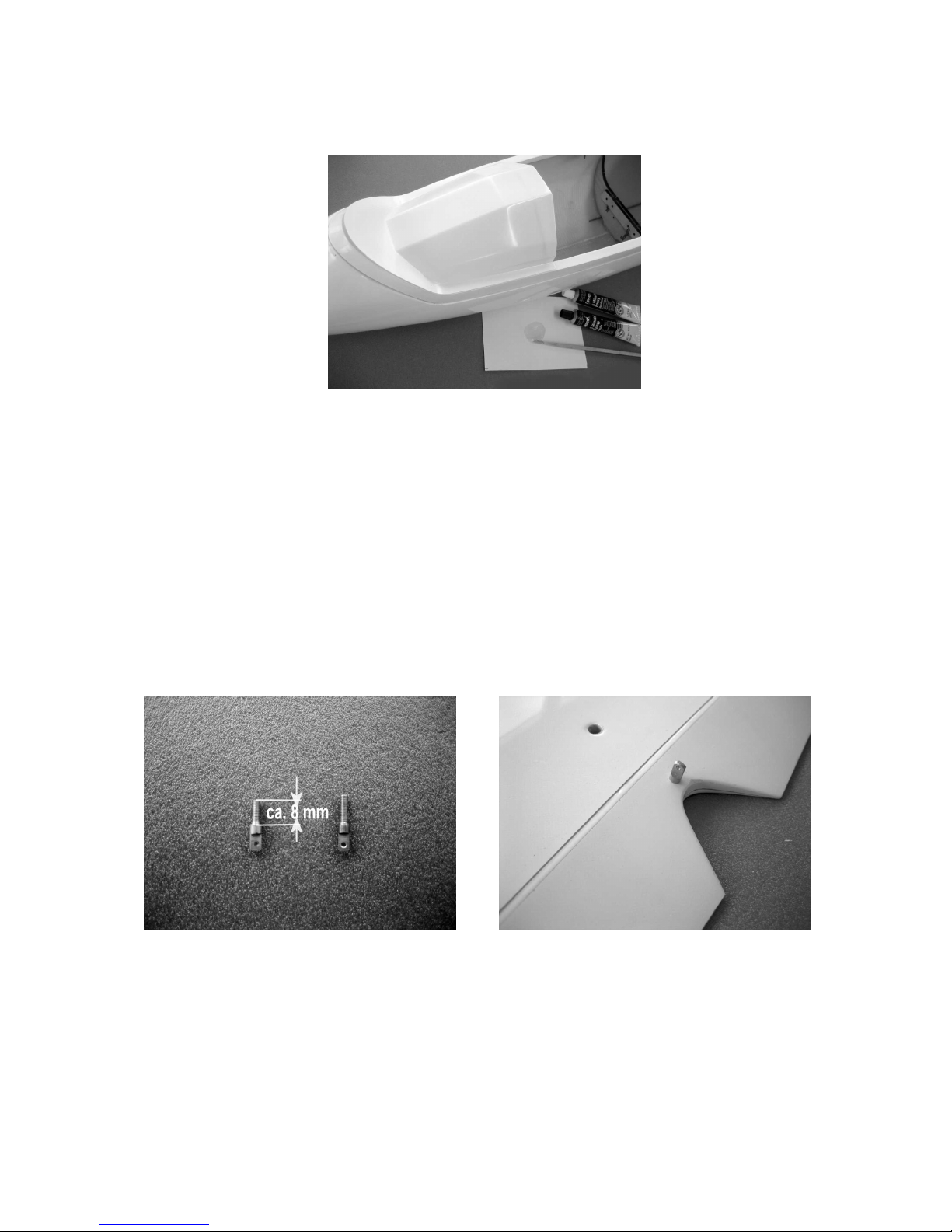
Auf der Unterseite des Rumpfes ist die Größe für die Fahrwerksklappen
angezeichnet. Mit einer feinen Säge z.B. Best.-Nr. 860 oder 860.1 aus dem Rumpf
heraustrennen. Dabei ist darauf zu achten, dass die beiden Klappen mit einem
äußeren Abstand zueinander von ca. 62 mm herausgetrennt werden.
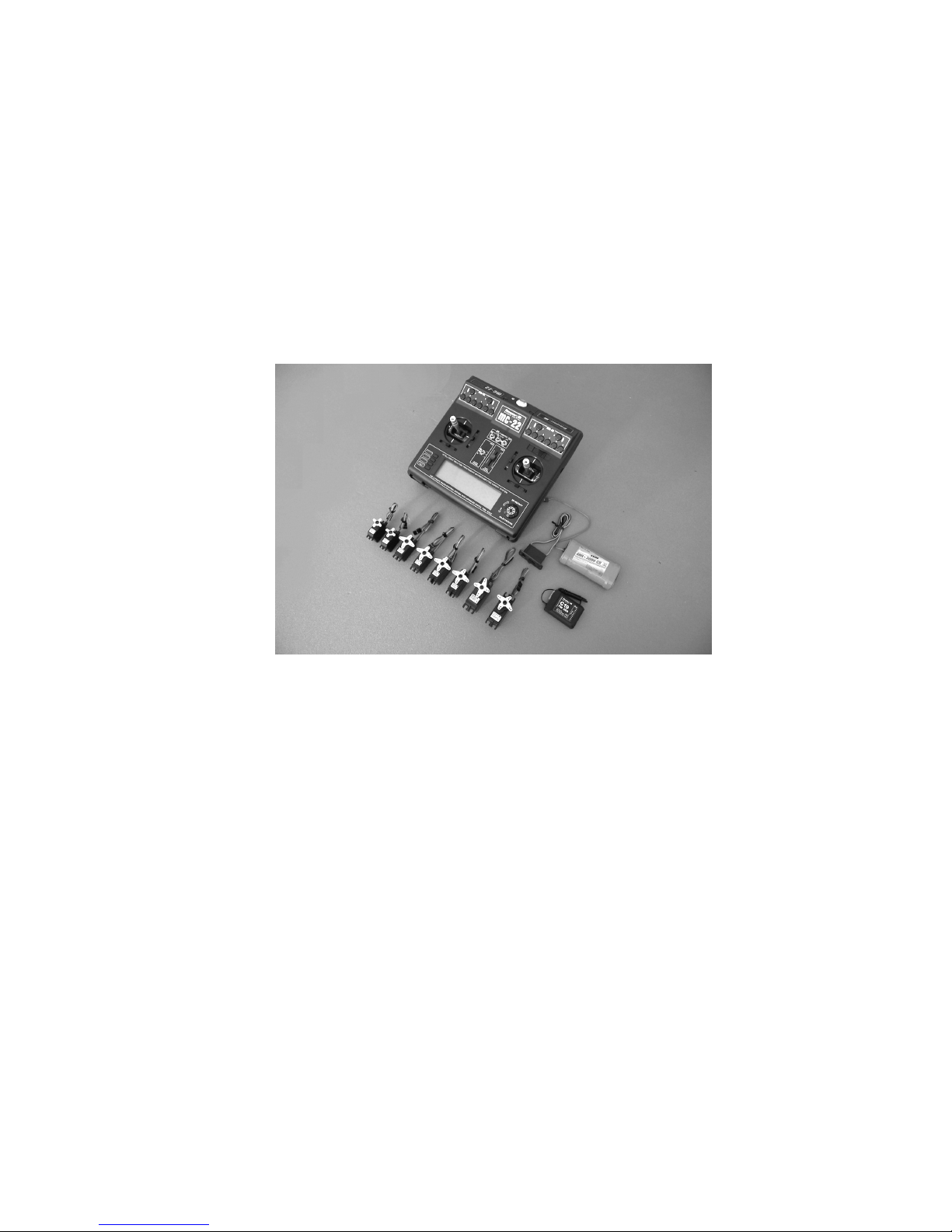
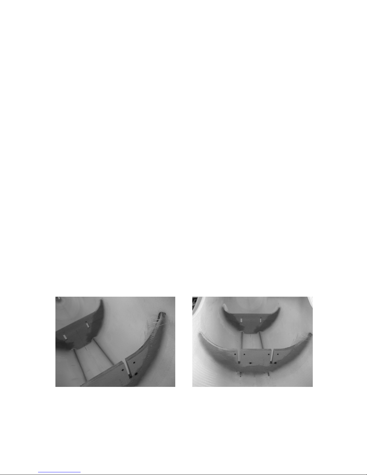
Die beiden Fahrwerksspanten mit Epoxydharz und Glasgewebe mit dem Rumpf
verkleben.
Nach dem Aushärten des Klebstoffes das überstehende Glasgewebe mit den
Spanten bündig schneiden.
Page 12
GRAUPNER GmbH & Co. KG D-73230 KIRCHHEIM/TECK GERMANY
Änderungen vorbehalten! Keine Haftung für Druckfehler Ident. # 0059200 10.2008
12
Als Anschlag, beim Schließen der Klappen auf die Innenseite des Rumpfes zwei UScheiben kleben.
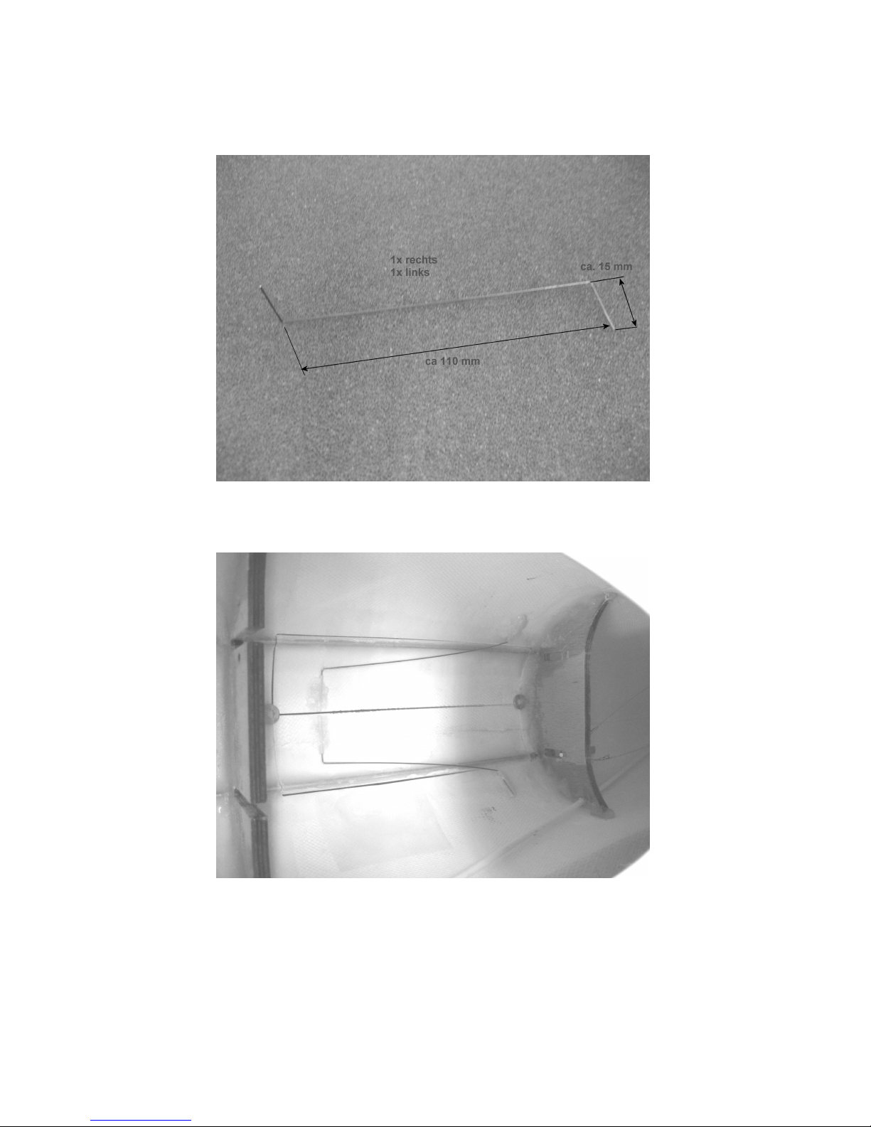
Zum Verschließen der Klappen werden Torsionsfedern eingeklebt siehe Foto.
Die Befestigung der beiden Enden der Torsionsfeder erfolgt mittels zweier
Kunststoffröhrchen. Die Torsionsfedern werden nicht in den Kunststoffröhrchen
festgeklebt, um sie evtl. wechseln zu können.
Page 13
GRAUPNER GmbH & Co. KG D-73230 KIRCHHEIM/TECK GERMANY
Änderungen vorbehalten! Keine Haftung für Druckfehler Ident. # 0059200 10.2008
13
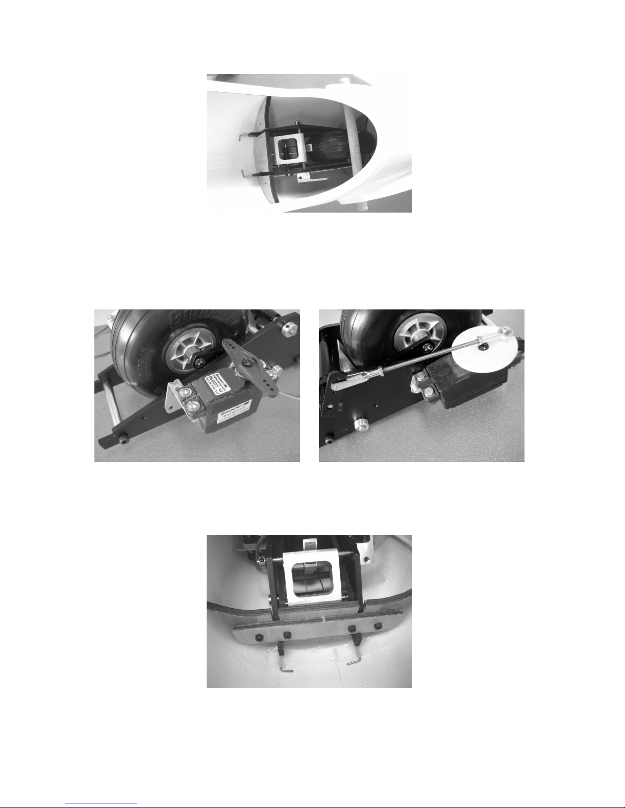
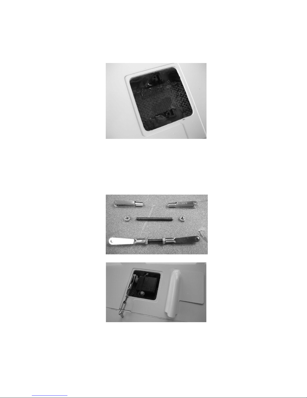
Als nächsten Arbeitsgang werden die Servos für Seitenruder und Fahrwerk an dem
Einziehfahrwerk befestigt (siehe Fotos) Wie auf dem Foto zu sehen, das
Anlenkgestänge für das Fahrwerk zusammenschrauben und montieren, es besteht
aus einer Gewindestange M 2,5 einem M2,5 Gabelkopf zwei Muttern M 2,5 und
einem Kugelgelenk M 2,5
Jetzt das Fahrwerk in den Rumpf setzen und mittels Sperrholzstreifen und vier
Inbusschrauben wie auf dem Foto zu sehen, sichern.
Page 14
GRAUPNER GmbH & Co. KG D-73230 KIRCHHEIM/TECK GERMANY
Änderungen vorbehalten! Keine Haftung für Druckfehler Ident. # 0059200 10.2008
14
Für die Radbremse, bei ausgefahrenem Einziehfahrwerk, wird mittels der
Metallservohalterung das Betätigungsservo an den vorderen Spant geschraubt.
Die dem Einziehfahrwerk beiliegende Kunststoffabdeckung entsprechend
zurechtschneiden und auf das Fahrwerk aufsetzen. Mit zwei Klebestreifen, rechts
und links, sichern.
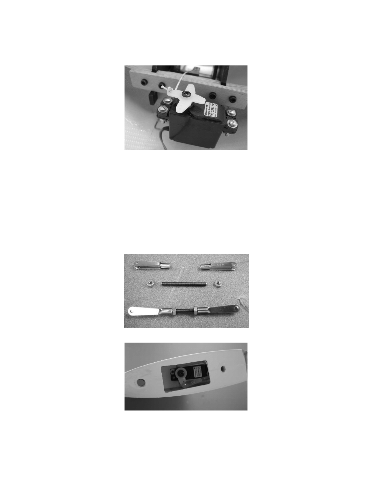
Vor dem Einbau des Spornrades muss das Höhenruderservo eingebaut werden.
Die Rumpfanformung des Spornfahrwerks abschneiden. Das Anschlusskabel des
Servos mittels einem Verlängerungskabel Best.-Nr. 3935.180 verlängern. Das Kabel
von oben durch die Öffnung in der Seitenflosse so in den Rumpf schieben, dass es
bis zur Kabinenöffnung reicht. Hierbei ist die Öffnung für das Spornrad behilflich. Für
die Servobefestigungsschrauben entsprechende Löcher in das Servobrettchen
bohren und das Servo befestigen. Das Höhenrudergestänge besteht aus einer M 2,5
Gewindestange, zwei Muttern M 2,5 und zwei Gabelköpfen M 2,5. Die Länge von
Einhängezapfen bis Einhängezapfen beträgt ca. 62 mm.
Page 15

GRAUPNER GmbH & Co. KG D-73230 KIRCHHEIM/TECK GERMANY
Änderungen vorbehalten! Keine Haftung für Druckfehler Ident. # 0059200 10.2008
15
Wie auf dem Foto zu sehen, die Abdeckung für das Spornfahrwerk, bohren und
einpassen.
Für die Radachse ca. 11 mm oberhalb der Unterkante des Rumpfes ein Loch mit Ø 3
mm bohren. Die Abdeckung wird so in den Rumpf geklebt, dass die beiden Stellringe
in den Aussparungen sind. Jetzt kann das Rad zusammen mit den beiden Stellringen
montiert werden.
Das Seitenruder mittels dem GFK-Stab an den Rumpf montieren und die Position der
Markierung für die Gewindestange der Seitenruderanlenkung überprüfen. Mit einem
Ø 3mm Bohrer an dieser Stelle ein Loch durch das Seitenruder bohren. Die beiden
Anlenklaschen, wie auf dem Foto zu sehen mittels der Gewindestange an das
Seitenruder montieren.
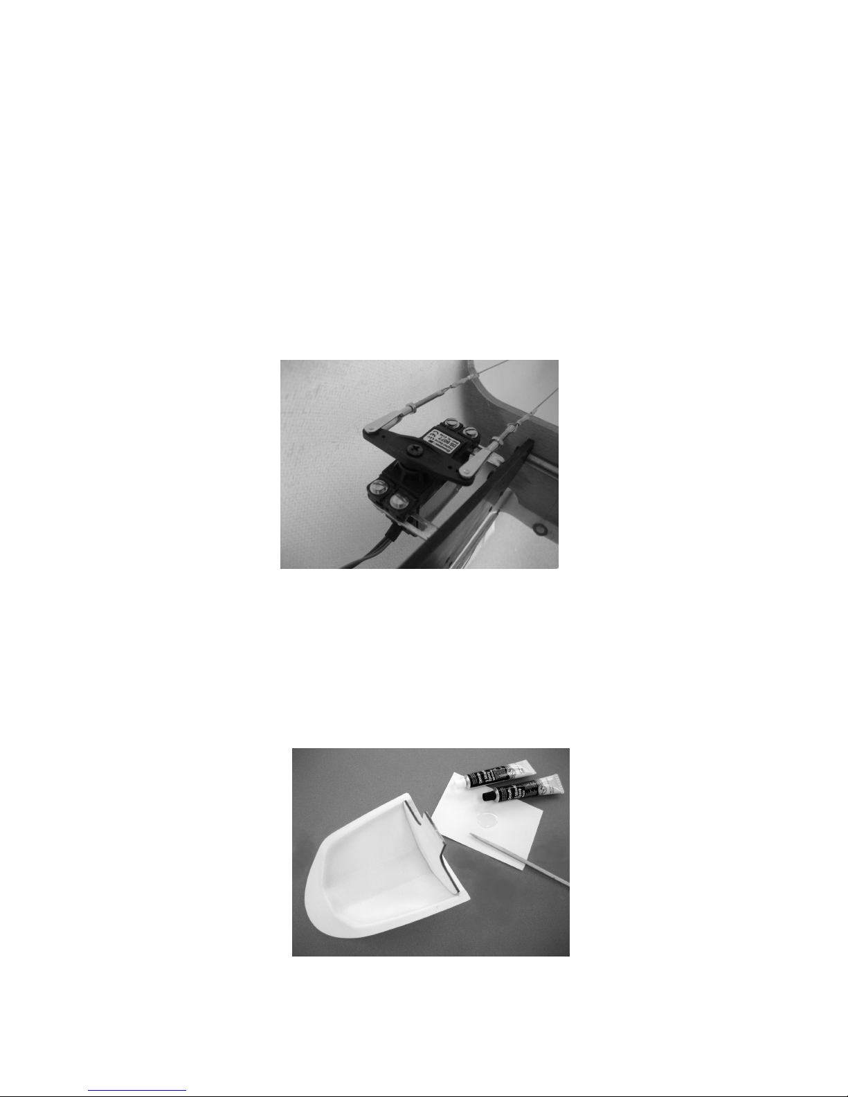
Jetzt wie auf den nachstehenden Fotos zu sehen die Seilzuganlenkung montieren.
Page 16
GRAUPNER GmbH & Co. KG D-73230 KIRCHHEIM/TECK GERMANY
Änderungen vorbehalten! Keine Haftung für Druckfehler Ident. # 0059200 10.2008
16
Stahlseile zuerst durch das Aluminiumröhrchen (Ø2/1,6x15 mm) dann durch die
Querbohrung der Augenschraube und dann wieder durch das Aluminiumröhrchen.
Mit einer Rundzange das Aluminiumröhrchen an zwei Stellen, wie auf dem Foto zu
sehen, fest zusammendrücken. An den Enden des Aluminiumröhrchens das Stahlseil
zusätzlich zusammenlöten.
Jetzt werden die Gabelköpfe in die Anlenklaschen eingehängt. Die freien Enden der
Strahlseilanlenkungen so in den Rumpf schieben, dass sie bis zur
Kabinenhaubenöffnung reichen.
Das Seitenruder mittels dem GFK-Stab an den Rumpf montieren.
Am Seitenruder werden die beiden Seilzüge wie schon beschrieben am Servohebel
eingehängt, siehe Foto, dabei darauf achten, dass sich die beiden Seile
überkreuzen, damit sie nicht an der Rumpfseitenwand streifen.
Der Instrumentenpilz kann fest an den Kabinenhaubenrahmen geklebt oder in den
Rumpf geschraubt oder wie beim Original, zum Aufschwenken in den Rumpf montiert
werden.
Die Kabinenhaube mit Instrumentenpilz
Der Kabinenhaubenrahmen ist werkseitig fertig am Rumpf angeschlagen, d.h. er
lässt sich wie beim Original, nach dem Zurückziehen des Verriegelungsstiftes zur
Seite schwenken. In den Instrumentenpilz wie auf dem Foto zu sehen das
Instrumentenbrett kleben.
Page 17
GRAUPNER GmbH & Co. KG D-73230 KIRCHHEIM/TECK GERMANY
Änderungen vorbehalten! Keine Haftung für Druckfehler Ident. # 0059200 10.2008
17
Nach dem Trocknen des Klebstoffes wird der Instrumentenpilz auf den
Kabinenhaubenrahmen geklebt. Hierzu die Klebeflächen gut anschleifen.
Es besteht die Möglichkeit den Instrumentenpilz „scalemäßig „ im Rumpf zu
befestigen, dass er sich nach oben schwenken lässt. Diese Art der Befestigung ist
nach eigenem Ermessen durchzuführen. Vor dem Aufkleben der Kabinenhaube
muss der Rahmen und das Instrumentenbrett entsprechend dem Vorbild lackiert
werden. Hierzu gibt es in den Baumärkten hervorragende Effektlacke. Nach dem
Trocknen der Lackierung wird die Kabinenhaube aufgeklebt. Dies wird am besten mit
UHU ALLESKLEBER Kraft vorgenommen. Zum Schluss wird dann der Kabinenrand
noch weiß lackiert.
Das Höhenleitwerk
Das Gewinde der Ms-Ruderhörner auf 8 mm kürzen, und unter Zugabe von Klebstoff
bis zum Anschlag in die Gewindebohrung im Höhenruder eindrehen und ausrichten,
so dass später der Gabelkopf eingehängt werden kann
Der Tragflügel Ansteckflügel
Sämtliche Klebestellen, für die Servohalterungen, müssen mit Schleifpapier
angeschliffen werden, bis die Klebestellen matt werden (siehe auch Hinweis nach der
Klebstofftabelle).
Das Querruderservo wird so mit den Halterungen im Tragflügelaußenteil befestig,
dass das Gestänge genau auf das Ruderhorn trifft. Die beiden Servohalterungen,
aufgesteckt auf das Servo, mit Klebstoff im Tragflügel ankleben.
Page 18
GRAUPNER GmbH & Co. KG D-73230 KIRCHHEIM/TECK GERMANY
Änderungen vorbehalten! Keine Haftung für Druckfehler Ident. # 0059200 10.2008
18
Nach dem Trocknen des Klebstoffes das Servo herausnehmen und die beiden
Halterungen mit ausreichend Klebstoff festkleben. Dabei darauf achten, dass kein
Klebstoff in den Bereich der Servofläche kommt.
Nach dem Trocken des Klebstoffes das Servo einsetzen, Ruderhorn, Gewindelänge
auf 8 mm kürzen, eindrehen und Gestänge anfertigen. Das Gestänge besteht aus
einem Stück M 2,5 Gewindestange, zwei Muttern M 2,5 und zwei Gabelköpfen M 2,5
Die Länge der Gestänge von Einhängepunkt zu Einhängepunkt abmessen und
entsprechende Stücke von der M 2,5 Gewindestange abschneiden.
Page 19

GRAUPNER GmbH & Co. KG D-73230 KIRCHHEIM/TECK GERMANY
Änderungen vorbehalten! Keine Haftung für Druckfehler Ident. # 0059200 10.2008
19
Die beiliegenden Steuerkreuze nach dem Foto entsprechend beschneiden.
Bei Servomittelstellung muss sich auch das Querruder in Neutralstellung befinden.
Die Schraubverbindungen mit UHU schraubensicher gegen Lösen sichern. Die
Servoabdeckung wird mittels Klebestreifen befestigt.
Die Mitnahme des äußeren kleine Querruders erfolgt durch das Einkleben von einem
Strahlstift in das angesteuerte Querruder. Wie auf den nachfolgenden Fotos zu
sehen wird der Stahlstift zuerst soweit in das Querruder geschoben, dass er noch ca.
2,5 mm heraussteht. Dies entspricht Querrudervollausschlag nach unten.
Mit einer Spitzzange den Stahlstift jetzt, ca. 5 mm tief in das äußere Querruder
schieben.
Durch Einspritzen von Klebstoff in das Querruder den Stahlstift gegen
Herausrutschen sichern.
Innenflügel
Für die Ruderhörner durch den Steg in den Rudern einen Schlitz genau in der Mitte
der Abdeckhutzen feilen. Der Steg im Tragflügel muss für die Gewindestange und
Page 20

GRAUPNER GmbH & Co. KG D-73230 KIRCHHEIM/TECK GERMANY
Änderungen vorbehalten! Keine Haftung für Druckfehler Ident. # 0059200 10.2008
20
Gabelkopf ebenfalls durchbrochen werden. Die Ruderhörner werden so in die Ruder
geklebt, dass sie zum Einen auf der Unterschale aufstehen zum Anderen, dass die
Einhängebohrung für den Gabelkopf mit dem Drehpunkt der Ruder übereinstimmt
Damit die Wölbklappen auch nach oben ausschlagen können müssen die
Gestängeabdeckungen, am Flügel nicht am Ruder, ca 2 mm schräg geschliffen
werden, so dass bei Ruder in Neutralstellung, oben gemessen ein Abstand, von
ca. 2 mm entsteht, hierzu die Wölbklappen auf Vollausschlag nach unten festhalten.
Beim Landeklappenservo wird die Einhängebohrung mit Hebelarm 11mm mit einem
Bohrer Ø 2 mm aufgebohrt. Jetzt den Gestängeanschluss montieren, die STOPMutter nur so fest anziehen, dass sich der Gestängeanschluss noch ohne merkliches
Spiel drehen lässt.
Die Servoanschlusskabel mit den entsprechenden Verlängerungskabel verlängern.
Die Servohalterungen werden so in den Tragflügel geklebt, dass die Anlenkgestänge
genau auf die Ruderhörner treffen. Das Servo für die Landeklappe wird so mit den
Kunststoffhalterungen in dem Tragflügel befestigt, dass das Anlenkgestänge genau
auf die Querbohrung des Gestängeanschlusses trifft.
Page 21

GRAUPNER GmbH & Co. KG D-73230 KIRCHHEIM/TECK GERMANY
Änderungen vorbehalten! Keine Haftung für Druckfehler Ident. # 0059200 10.2008
21
Wie schon bei den Querruder an den Ansteckflügel beschrieben, die Rudergestänge
aus M 2,5 Gewindestange, Muttern M2, 5 und Gabelköpfen M 2,5 herstellen. Die
Länge der Gestänge von Einhängepunkt zu Einhängepunkt abmessen und
entsprechende Stücke von der M 2,5 Gewindestange abschneiden. Die beiden
Kunststoffhalterungen für das Landeklappenservo müssen in der Höhe um ca. 1 mm
gekürzt werden, damit das Servo festgeklemmt werden kann.
Bei den Servos für die Landeklappen muss wie folgt vorgegangen werden: das Servo
so in die Halterung stecken, dass das Anlenkgestänge durch die Querbohrung des
Gestängeanschlusses kommt ( wie auf dem Foto zu sehen). Servo mittels
Fernsteuerung auf Position eingefahren bringen. Die Landeklappe durch Druck auf
das Gestänge in Position eingefahren halten. Unter Zugabe von UHU
schraubensicher den Gewindestift in den Gestängeanschluss drehen und Gestänge
festklemmen.
Die Servoabdeckungen werden mittels Klebestreifen befestigt.
Einbau der Tragflächensicherung
In die beiden Wurzelrippen unter Zugabe von Klebstoff die Stecknippel in die
Wurzelrippen bis Anschlag einschrauben.
Die beiden Aluminiumgewindebuchsen mittels dem Gewindestift M8
zusammenschrauben und auf eine Länge von ca. 130 mm kürzen. Die beiden
Schnellverschlusskupplungen in die Aluminiumgewindebuchse eindrehen.
Page 22

GRAUPNER GmbH & Co. KG D-73230 KIRCHHEIM/TECK GERMANY
Änderungen vorbehalten! Keine Haftung für Druckfehler Ident. # 0059200 10.2008
22
Das Modell probeweise zusammenbauen, um die Passgenauigkeit zu kontrollieren.
Wenn die Länge der Flächensicherung stimmt, wird diese wieder ausgebaut und die
Schnellverschlusskupplungen etwa 5 mm herausgedreht, um SchraubensicherungsLack auftragen zu können. Jetzt bis zum Trocknen des Lackes das Modell wieder
zusammenbauen. Es muss sichergestellt sein, dass die beiden Flächenhälften am
Rumpf anliegen und die beiden Schnellverschlusskupplungen eingerastet sind.
Zum Lösen der Schnellverschlusskupplungen den Überwurfring mit einem
Schraubendreher zurückschieben und die Tragflächenhälften vom Rumpf abziehen.
Die Verriegelung dient bei einer etwas härteren Landung auch als Abstützung für den
Rumpf.
Einbau von EIN/AUS-Schalter und Empfängerakku
Der EIN/Aus-Schalter wird mit den dem Schalter beiliegenden Schrauben in dem
Brettchen in der Rumpfspitze befestigt. Der Empfängerakku kann mittels
Klettkabelbinder auf dem Brettchen befestigt werden.
Für den F-Schlepp kann die Kupplung Best.-Nr. 2890 oder 7890.2 in die Rumpfspitze
eingeklebt werden. Das Betätigungsservo wird in das Brettchen in der Rumpfspitze
montiert. Bei Verwendung der 2890 Kupplung liegt das Betätigungsgestänge in Form
einer M2,5 Gewindestange der Kupplung bei. Beim Einbau der Kupplung 7890.2
muss das Gestänge aus einer M2,5 Gewindestange mit jeweils einer M2,5 Mutter
und zwei Gabelköpfen M 2,5 zusammengeschraubt werden. In beiden Fällen muss
die Länge des Gestänges exakt eingestellt werden, d.h. es muss eine sichere
Betätigung der Kupplung gewährleistet sein. Die Kupplung muss so eingestellt
werden, dass das Servo im ein- und ausgefahrenen Zustand nicht mechanisch
begrenzt wird.
Der Zusammenbau von VENTUS 2 cx
Flächenverbinder durch den Rumpf schieben. Tragflügel- Innenflügel soweit auf den
Verbinder schieben, dass die Servokabel zusammengesteckt werden können.
Die beiden Tragflügel-Innenflügel werden mittels der selbst einrastenden
Flügelsicherung am Rumpf gesichert. Zum Anstecken der beiden Ansteckflügel von
dem beiliegenden CFK-Rundstab Ø 12 mm jeweils ein Stück mit ca. 158 mm Länge
abschneiden. Jetzt die Ansteckflügel mittels CFK-Rundstab und GFK-
Page 23

GRAUPNER GmbH & Co. KG D-73230 KIRCHHEIM/TECK GERMANY
Änderungen vorbehalten! Keine Haftung für Druckfehler Ident. # 0059200 10.2008
23
Verdrehsicherungen Ø 4 mm soweit an die Innenflügel stecken, dass die Servokabel
zusammengesteckt werden können. Die Winglets mittels zweier GFK-Rundstäben
Ø 4 mm an die Ansteckflügel stecken. Die Winglets und die Ansteckflügel werden
mittels Klebestreifen, über die gesamte Profiltiefe, oben und unten, gegen
herausrutschen gesichert.
Den Gabelkopf des Höhenrudergestänges in das Ruderhorn einhängen und das
Höhenleitwerk mittels der beiden M 5 Inbusschrauben auf dem Rumpf befestigen.
Das Auswiegen von VENTUS 2 cx
Das komplett ausgerüstete Modell, sprich flugfähig, rechts und links neben dem
Rumpf, ca.107 -111 mm hinter der Nasenleiste, unterstützen. Jetzt sollte das Modell
sich waagerecht auspendeln, bzw. die Rumpfnase leicht nach unten zeigen, bei einer
EWD von ca. 1-1,5 ° Der notwendige Ballast muss dauerhaft und unverrückbar im
Rumpf befestigt werden.
Für die ersten Flugversuche sollte der Schwerpunkt an die vordere angegebene
Position gelegt werden.
Vor dem ersten Flug müssen sämtliche Ruder, bei Sendertrimmung in Mitte, genau
auf Mittelstellung (Neutralstellung) gebracht werden.
Ruderausschläge VENTUS 2 cx
Seitenruder +/- 55 mm
Höhenruder +/- 10 mm
Querruder nach oben 17 mm
nach unten 4 mm
mittleres Querruder nach oben 15 mm
nach unten 4 mm
Wölbklappe nach oben 8 mm
nach unten 4 mm
Bei Querruderausschlag bewegen sich alle Ruder. Bei den angegebenen
Ausschlägen erreichen die äußeren Querruder einen größeren Ausschlag als die
inneren Wölbklappen.
Exponential-Wert für Querruder 33 %
für Höhenruder 26 %
Klappenstellung für Thermikflug:
Wölbklappen nach unten positiv 3 mm
mittleres Querruder nach unten positiv 2,5 mm
Querruder nach unten positiv 2 mm
Klappenstellung für Schnellflug:
Wölbklappen nach oben negativ 2 mm
mittleres Querruder nach oben negativ 1,5 mm
Querruder nach oben negativ 1 mm
Klappenstellung für die Landung:
Landeklappen voll ausgefahren
Wölbklappen nach unten
Page 24

GRAUPNER GmbH & Co. KG D-73230 KIRCHHEIM/TECK GERMANY
Änderungen vorbehalten! Keine Haftung für Druckfehler Ident. # 0059200 10.2008
24
mittleres Querruder nach oben
Querruder bleiben in Neutralstellung
Die angegebenen Ausschläge sind maximale Ruderausschläge, die durch DUALRATE und EXPONENTIAL verfeinert werden können. Bei den Ruderausschlägen
handelt es sich nur um Empfehlungen, die den eigenen Vorstellungen angepasst
werden können oder angepasst werden müssen.
Gemessen wird immer an der größten Rudertiefe.
Ferner wird benötigt (im Baukasten enthalten)
Dekorbogen
Ferner wird benötigt ( nicht im Baukasten enthalten)
UHU plus endfest 300 Best.-Nr. 950.43
UHU schraubensicher Best.-Nr. 952
Trimmballast Best.-Nr. 536
Wichtig:
Bei der Montage der Gestänge grundsätzlich sorgfältig darauf achten, dass diese
leicht laufen, ihren vollen steuerbaren Weg – einschließlich Trimmung – ausführen
können und keinesfalls mechanisch begrenzt werden.
Bei Bewegen des Steuerknüppels nach rechts, muss das Seitenruder nach rechts
ausschlagen. Beim Bewegen des Höhen/Tiefenruder-Knüppels nach hinten, sprich
zum Bauch, muss das Höhenruder nach oben ausschlagen (nach vorne = unten).
Beim Bewegen des Querruder-Steuerknüppels nach rechts, müssen die Ruder an
der rechten Tragfläche nach oben, die an der Linken nach unten ausschlagen.
Die Landeklappen fahren aus, wenn der nichtneutralisierende Steuerknüppel nach
hinten bewegt wird.
Für die Klappenstellungen Thermikflug und Schnellflug programmiert man am besten
einen Drei-Funktions-Knüppelschalter. Schalter nach vorne Schnellflug, Schalter in
der Mitte Normalflug, Schalter nach hinten Thermikflug.
Nun bleibt nur noch viel Spaß und Freude beim Fliegen mit Ihrem VENTUS 2 cx zu
Wünschen
Ihr Team
Page 25

GRAUPNER GmbH & Co. KG D-73230 KIRCHHEIM/TECK GERMANY
Änderungen vorbehalten! Keine Haftung für Druckfehler Ident. # 0059200 10.2008
25
Graupner
Order No. 9449
Instructions
VENTUS 2 cx
Model glider
for
slope-soaring and aero-tow
This model requires at least an eight-channel radio control system.
Specification
Wingspan approx. 5500 mm
Fuselage length approx. 1970 mm
Wing section HQ/W 3/13
Tailplane section HQ/W 0/10
Wing area approx. 104 dm²
Tailplane area approx. 9.4 dm²
Total surface area approx. 113.4 dm²
All-up weight according to
fittings, min. approx. 9500 g
Centre of Gravity approx. 107 - 111 mm back from the wing
root leading edge on both sides
Longitudinal dihedral approx. 1 - 1.5°
Be sure to read right through the instructions covering assembly and operation
of your model before you attempt to operate it for the first time. You alone are
responsible for the safe operation of your radio-controlled model. Young
people should only be permitted to build and fly this model under the
instruction and supervision of an adult who is aware of the hazards involved in
this activity.
If you have any questions regarding the safe operation of your RC model
aircraft, please turn to your local model shop in the first instance, as the staff
will be pleased to help you.
Radio-controlled model aircraft are very demanding and potentially dangerous
machines, and call for a high level of technical knowledge and skill from the
operator, together with a responsible attitude.
Page 26

GRAUPNER GmbH & Co. KG D-73230 KIRCHHEIM/TECK GERMANY
Änderungen vorbehalten! Keine Haftung für Druckfehler Ident. # 0059200 10.2008
26
In legal terms our models are classed as aircraft, and as such are subject to
statutory regulations and restrictions which must be observed. Our brochure
“Modellflugrecht, Paragrafen und mehr” (Model Aviation Law, Legal
Requirements and more) is available under Order No. 8034.02, and contains a
summary of all these rules; your local model shop should have a copy which
you can read. There are also Post Office regulations concerning your radio
control system, and these must be observed. Refer to your RC system
instructions for more details.
It is important to use only those parts included in the kit, together with other
genuine Graupner accessories and replacement parts as recommended
expressly by us. Even if you change a single component, you can no longer be
sure that the whole system will work reliably, and such changes also invalidate
your guarantee.
Use only matching polarised connectors.
Avoid short circuits and reverse polarity at all times.
The high energy density of NiMH batteries involves a permanent risk of fire and
even explosion.
A radio-controlled model aircraft can only work properly and fulfil your
expectations if it is built very carefully and in accordance with the building
instructions. If you wish to avoid injuring people and damaging property, it is
essential to be careful and painstaking at all stages of building and operating
your model. Nobody would climb into a full-size sailplane and try to fly it
without completing a course of training first. Model flying is just such a skill,
and has to be learned in exactly the same way.
However, as manufacturers we have no means of influencing the way you build
and operate your RC model aircraft, and for this reason we can do no more
than point out the hazards expressly. We accept no further liability.
If you need help, please enlist the aid of an experienced modeller, join a model
club or enrol at a model flying training school. Model shops and the specialist
model press are also good sources of information. The best course is always
to join a club and fly at the approved model flying site.
Adhesives and paints contain solvents which may be hazardous to health
under certain circumstances. Read and observe the notes and warnings
supplied by the manufacturer of these materials.
The operator of the model must be in full possession of his or her bodily and
mental faculties. As with car driving, flying a model aircraft under the influence
of alcohol or drugs is highly dangerous and not permissible under any
circumstances.
Make sure that all passers-by and onlookers are aware of the hazards involved
in the operation of your model.
Page 27

GRAUPNER GmbH & Co. KG D-73230 KIRCHHEIM/TECK GERMANY
Änderungen vorbehalten! Keine Haftung für Druckfehler Ident. # 0059200 10.2008
27
Keep a safe distance between your model and other people or objects. Never
fly low over people or directly towards them.
Radio-controlled models should only be flown in “normal” weather conditions,
i.e. a temperature range of -5° to +35°C. More extreme temperatures can lead to
changes in battery capacity, material characteristics, the strength of glued
joints and other unwanted effects.
All model flyers should behave in a way which minimises the danger to people
and property. Never act in any manner which will disturb other pilots, or have
an adverse effect on safe, orderly flying at the site.
Don’t operate your model in the vicinity of overhead power cables, industrial
sites, residential areas, public roads, squares, school playgrounds, public
parks or sports fields etc.
Don’t ignore our warnings. They refer to hazardous materials and processes
which, if ignored, can result in fatal injury or serious damage to property.
Every time you intend to fly the model, check carefully that all parts connected
to it are working correctly, including RC components, control surface horns
etc. Everything must be properly located and firmly secured. Check for
possible damage, and do not fly your model unless you are confident that
everything is in perfect order.
Whenever you are holding the model, make sure that you are standing on a
safe surface and cannot slip. Wear shoes with high-grip soles, such as
trainers.
Satisfy yourself that your frequency is vacant before you switch on. Radio
interference caused by unknown sources can occur at any time without
warning. If this should happen, your model will be uncontrollable and
completely unpredictable. Never leave your radio control system unguarded,
as other people might pick it up and try to use it.
If you are to fly your model safely and avoid problems, it is essential that you
are aware of its position and attitude throughout each flight - so don’t let it fly
too far away! If you detect a control problem or interference during a flight,
immediately land the model to prevent a potential accident. Model aircraft must
always give way to full-size aircraft. Take-off and landing strips should be kept
free of people and other obstacles.
Your RC system can only work reliably if the batteries are kept fully charged.
Never use hot, faulty or damaged batteries. It is important to observe the
instructions supplied by the battery manufacturer.
Before every flight ensure that all functions are working correctly, and carry
out a range check.
Page 28

GRAUPNER GmbH & Co. KG D-73230 KIRCHHEIM/TECK GERMANY
Änderungen vorbehalten! Keine Haftung für Druckfehler Ident. # 0059200 10.2008
28
Always switch on the transmitter first, then the receiving system. When
switching off, reverse the order: receiving system first, then the transmitter.
Check that the control surfaces work in the correct “sense”, i.e. they deflect in
the direction which corresponds to the movement of the stick.
After each session remove all the batteries from the model and store them in a
discharged state (approx. 0.9 V per cell) at a temperature of about +5° to +25°
C. They must be kept out of the reach of children.
Please don’t misunderstand the purpose of these notes. We only want to make
you aware of the many dangers and hazards which can arise if you lack
knowledge and experience, or work carelessly or irresponsibly. Provided that
you take reasonable care, model flying is a highly creative, instructive,
enjoyable and relaxing pastime.
Notes on the use of NiMH batteries
Application
All Graupner NiMH battery packs and single cells are designed exclusively for typical
modelling applications in model aircraft, boats and cars.
Charging
1. NiMH batteries must always be charged using a suitable standard charger or fast
charger. For more information see the main Graupner FS catalogue.
2. Before charging an NiMH pack, allow it to cool down to ambient temperature, i.e.
approx. 20º C. The battery should not be charged until just before use, as all
NiMH cells have a natural tendency to self-discharge due to their construction.
3. Warning:
The charge process must be supervised even if you are using a fully automatic
charger. Note the maximum permissible charge current printed on the pack or
individual cells, and do not exceed that value. Excessive charge currents can
cause NiMH cells to overheat. If the battery heats up to about 50° C when on
charge, the charge current must be switched off immediately. When NiMH cells
get hot, the pressure inside the cell case rises greatly. Every NiMH cell in a pack
is fitted with a pressure valve which is designed to prevent it exploding
dangerously in an emergency. However, the valves may be blocked or
malfunction for some other reason, which means that an explosion is always
possible if the cell overheats seriously.
4. Warning:
If you accidentally overcharge an NiMH pack, do not touch it! Switch off the
charge current and allow the pack to cool down naturally.
5. Warning:
It is essential to avoid short-circuits involving NiMH packs. The result is an
extremely high rate of discharge which heats up the battery immediately, and this
Page 29

GRAUPNER GmbH & Co. KG D-73230 KIRCHHEIM/TECK GERMANY
Änderungen vorbehalten! Keine Haftung für Druckfehler Ident. # 0059200 10.2008
29
can cause cells to burst in the same way as an overheated pack. The explosion
itself represents a serious risk of injury, and any corrosive electrolyte which
escapes from the cell can cause chemical burns.
If electrolyte escapes from a cell, take great care to avoid it getting on your skin
or in your eyes. If this should happen, rinse immediately with copious quantities
of water and seek medical assistance.
6. Never solder a wire or anything else directly to the cell case, as this may damage
the pressure valve.
7. Warning:
Never dispose of faulty or exhausted NiMH batteries in a fire, as they may
explode. Don’t discard them in the household rubbish, as they constitute toxic
waste and require special treatment. Take them to your local toxic waste
collection point (ask your local council for details). It costs nothing to dispose of
exhausted cells properly, and helps preserve a clean environment, as most of the
materials can be recycled.
Building and flying the VENTUS 2 cx
Before you start building:
It is important to install the RC components and control linkages in the model at the
appropriate stage of construction. In most cases it is very difficult or even impossible
to fit these components at a later stage.
If you intend buying a new radio control system for your model, ensure that the
transmitter and receiver are designed for model aircraft use, are type-approved and
are licensed by your national Post Office authority.
The frequency bands which we use for radio control systems are shared by other
radio equipment and radio frequency apparatus. For this reason it is not possible to
guarantee that your RC system will not suffer interference in use.
For more information on this subject please enquire at your local Post Office, or ask
at your nearest model shop.
During construction
When handling adhesives and solvent-based materials it is important to observe the
safety notes and instructions supplied by the manufacturer. Many glues and solvents
are capable of causing injury and damage to materials if they are not used
competently. Take waste glue and paint to your local model shop or toxic waste
collection centre.
Note that balsa knives, pins, etc. have sharp points and edges, and should be
handled carefully to avoid injury.
Take care to keep tools, adhesives and paints out of the reach of children.
A large, unobstructed working surface is a great advantage for all types of modelmaking.
If you are a relative beginner and are not sure of any process, ask an
experienced modeller for help.
Page 30

GRAUPNER GmbH & Co. KG D-73230 KIRCHHEIM/TECK GERMANY
Änderungen vorbehalten! Keine Haftung für Druckfehler Ident. # 0059200 10.2008
30
Flying the model
Never fly your VENTUS 2 cx in a nature reserve or any other protected site. Please
don’t disturb the animals and plants which live in the countryside.
Trees and bushes are the natural habitat of many birds, and also serve as nesting
sites and general protection for them.
Important safety notes
You have acquired a kit which can be assembled into a fully working RC model when
fitted out with suitable accessories. However, we as manufacturers have no control
over the way you build and fly your RC model aircraft, nor how you install, operate
and maintain the associated components, and for this reason we are obliged to deny
all liability for loss, damage or costs which are incurred due to the incompetent or
incorrect use and operation of our products, or which are connected with such
operation in any way. Unless otherwise prescribed by binding law, the obligation of
the GRAUPNER company to pay compensation, regardless of the legal argument
employed, is excluded. This includes personal injury, death, damage to buildings,
damage due to loss of business or turnover, interruption of business or other direct or
indirect consequent damage whose root cause was the operation of the model.
The total liability in all cases is limited to the amount of money which you actually
paid for this model.
This model aeroplane is built and flown at the sole and express responsibility of the
operator. The only way to avoid injury to persons and damage to property is to
handle and operate the model with the greatest care and consideration at all times.
Before you fly the model for the first time you must take out a special
insurance policy designed to cover modelling risks.
These safety notes should be kept in a safe place. If you ever dispose of the
model, be sure to pass them on to the new owner.
Manufacturer’s declaration:
If material defects or manufacturing faults should arise in a product distributed by us
in the Federal Republic of Germany and purchased by a consumer (§ 13 BGB), we,
Graupner GmbH & Co. KG, D-73230 Kirchheim/Teck, Germany, acknowledge the
obligation to correct those defects within the limitations described below.
The consumer is not entitled to exploit this manufacturer’s declaration if the failure in
the usability of the product is due to natural wear, use under competition conditions,
incompetent or improper use (including incorrect installation) or external influences.
This manufacturer’s declaration does not affect the consumer’s legal or contractual
rights regarding defects arising from the purchase contract between the consumer
and the vendor (dealer).
Extent of the guarantee
If a claim is made under guarantee, we undertake at our discretion to repair or
replace the defective goods. We will not consider supplementary claims, especially
for reimbursement of costs relating to the defect (e.g. installation / removal costs) and
Page 31

GRAUPNER GmbH & Co. KG D-73230 KIRCHHEIM/TECK GERMANY
Änderungen vorbehalten! Keine Haftung für Druckfehler Ident. # 0059200 10.2008
31
compensation for consequent damages unless they are allowed by statute. This does
not affect claims based on legal regulations, especially according to product liability
law.
Guarantee requirements
The purchaser is required to make the guarantee claim in writing, and must enclose
original proof of purchase (e.g. invoice, receipt, delivery note) and this guarantee
card. He must send the defective goods to us at his own cost, using the address
stated above.
The purchaser should state the material defect or manufacturing fault, or the
symptoms of the fault, in as accurate a manner as possible, so that we can check if
our guarantee obligation is applicable.
The goods are transported from the consumer to us and from us to the consumer at
the risk of the consumer.
Duration of validity
This declaration only applies to claims made to us during the claim period as stated
in this declaration. The claim period is 24 months from the date of purchase of the
product by the consumer from a dealer in the Federal Republic of Germany (date of
purchase). If a defect arises after the end of the claim period, or if the evidence or
documents required according to this declaration in order to make the claim valid are
not presented until after this period, then the consumer forfeits any rights or claims
from this declaration.
Limitation by lapse of time
If we do not acknowledge the validity of a claim based on this declaration within the
claim period, all claims based on this declaration are barred by the statute of
limitations after six months from the time of implementation; however, this cannot
occur before the end of the claim period.
Applicable law
This declaration, and the claims, rights and obligations arising from it, are based
exclusively on the pertinent German Law, without the norms of international private
law, and excluding UN retail law.
The following points are important and must be observed at all times:
• Before you fly the model check that the radio control system is working reliably,
and that all connections are secure.
• The batteries must be charged and the range of the radio control system must be
checked before you operate the model. In particular, the radio control system
batteries must be fully charged before each session.
• Ensure that the channel you intend to use is not already in use by other
modellers. Never fly the model if you are not certain that your channel is free.
• Read and observe the instructions and recommendations provided by the
manufacturer of your radio control system and accessory components.
• Ensure that the servos are not mechanically obstructed at any point in their
travel.
Page 32

GRAUPNER GmbH & Co. KG D-73230 KIRCHHEIM/TECK GERMANY
Änderungen vorbehalten! Keine Haftung für Druckfehler Ident. # 0059200 10.2008
32
• Dry cells and rechargeable batteries must never be short-circuited.
• Remove all batteries from the model prior to transporting and storing it.
• Do not subject the model to dirty or cold conditions, or high levels of humidity or
heat.
• Secure the model and your RC equipment carefully when transporting them.
They may be seriously damaged if they are free to slide about,.
• IMPORTANT: when the flight battery is exhausted, you must not dispose of it in
the household waste. Take the pack to your local battery reclamation centre.
IMPORTANT: when the useful life of the model and the transmitter are over, do
not discard them in the domestic rubbish. The electric and electronic components
in particular must be taken to your nearest electrical recycling centre. Ask your
local authority if you are not sure of its location.
Pre-flight checks
Check that the radio control system works correctly and at full range before every
flight: switch on the transmitter and the receiving system, and extend the transmitter
aerial to its full length; walk away from the model, and check that all the control
surfaces work smoothly and immediately at an appropriate distance; check also that
they deflect in the correct “sense” in relation to the stick movements.
If you are a relative beginner to this type of model flying, we recommend that you
enlist an experienced model pilot to help you check and test-fly the model.
Care and maintenance
• Clean the model carefully after every session. The model and RC components
should only be cleaned using suitable cleaning agents. Ask your model shop for
information.
Notes on building the model
Before you start assembling the model, it is important that you study the plan and
read the instructions right through to the end. Tools can be dangerous; be aware of
the hazards involved in using them.
Tools required to build the VENTUS 2 cx
Pencil (HB lead), felt-tip pen, setsquare, tape measure or metre rule, household
scissors, sharp narrow-bladed knife, e.g. balsa knife, Order No. 980, small electric
drill, set of twist drills, allen keys, syringe, Order No. 739.3.
Gluing different materials
The following table gives examples of some typical joints, but it makes no claim to be
comprehensive.
Page 33

GRAUPNER GmbH & Co. KG D-73230 KIRCHHEIM/TECK GERMANY
Änderungen vorbehalten! Keine Haftung für Druckfehler Ident. # 0059200 10.2008
33
Material Typical joint Adhesive
Order No.
GRP to Fuselage to UHU plus endfest 300
plywood servo plate Order No. 950.43
GRP to Fuselage to UHU plus endfest 300
aluminium aero-tow coupling Order No. 950.43
GRP to Instrument panel to UHU plus schnellfest
plywood instrument binnacle Order No. 962
Areas of the fuselage which are to be glued should be rubbed down with fine-grit
glasspaper to remove any lingering traces of mould release agent. Carefully remove
all sanding dust. Aim at reducing the glossy surface to a matt finish, otherwise there
is no chance of a durable glued joint between the fuselage and other parts.
When using adhesives it is important to observe the instructions supplied by the glue
manufacturer. The main Graupner FS catalogue includes many other types of
adhesive.
When you are using solvent-based adhesives be sure to provide good ventilation in
your workroom.
Read the manufacturer’s instructions.
Radio control system
We particularly recommend computer radio control systems such as the mc-19S, mc22S, mc-24, mx-22 or mx-24.
Recommended servos:
Rudder DS 8077 Order No. 5149 1
reqd.
Elevator DS 3068 Order No. 5188 1
reqd.
Ailerons DS 3068 Order No. 5188 2
reqd.
Outboard wing flaps DS 3328 Order No. 5157 2
reqd.
Inboard wing flaps DS 3328 Order No. 5157 2
reqd.
Airbrakes DS 3068 Order No. 5188 2
reqd.
Aero-tow release DS 8077 Order No. 5149 1
reqd.
Wheel brake DS 8077 Order No. 5149 1
reqd.
We recommend the DS 24 FM 35 S receiver.
Page 34

GRAUPNER GmbH & Co. KG D-73230 KIRCHHEIM/TECK GERMANY
Änderungen vorbehalten! Keine Haftung für Druckfehler Ident. # 0059200 10.2008
34
Order No. 3050 Power switch harness 1 required
Servo extension leads
Order No. 3935.105 for the ailerons 2 required
Order No. 3935.18 for connecting extension
leads to the receiver 2 required
Order No. 3935.11 for connecting extension
leads to the receiver 2 required
Order No. 3935.50 for connecting extension
leads to the receiver 1 required
Order No. 3935.180 for the elevator 1 required
Order No. 98516.1 Folding ferrite ring for the
aileron and airbrake servos 1 required
Order No. 1587 Velcro cable tie 1 pack
We recommend a receiver battery of at least 3 Ah capacity, e.g. Order No. 2490.4,
which should be properly prepared before use and maintained during its life, i.e. the
pack must be charged and discharged (cycled) several times before it reaches its full
stated capacity.
We deliberately recommend the use of rechargeable batteries for the receiver and
transmitter, as they offer the widest margin of safety in use.
Please see the main FS catalogue for details of suitable battery chargers.
Use foam rubber to pack round the receiver.
Assembling the VENTUS 2 cx
Please don’t start work on the model until you have read through the instructions and
have a clear understanding of the purpose of the various components and the
individual stages of construction. If you are not satisfied with the quality of any part,
take it back to your model shop for replacement before modifying it in any way.
The fuselage
Thoroughly sand all the joint areas inside the fuselage until they have a matt
appearance (see the note following the Adhesives table).
The outline of the wheel doors is marked on the underside of the fuselage. Use a
fine-blade saw, e.g. Order No. 860 or 860.1, to cut the doors out of the fuselage.
Note that the overall width of the wheel door opening should be about 62 mm.
Glue the two undercarriage formers in the fuselage and reinforce the joints
thoroughly with epoxy resin and woven glass cloth, as shown in the photographs.
Allow the epoxy to cure before cutting back the excess glass cloth flush with the
edges of the formers.
Page 35

GRAUPNER GmbH & Co. KG D-73230 KIRCHHEIM/TECK GERMANY
Änderungen vorbehalten! Keine Haftung für Druckfehler Ident. # 0059200 10.2008
35
Glue two washers to the inside of the fuselage to act as stops for the wheel doors.
The doors are held closed by a pair of torsion springs, which should be bent to the
shape shown in the photo and glued in place.
1 x right
1 x left
approx. 15 mm
approx. 110 mm
Both ends of the torsion springs are fitted in pieces of plastic tube which are glued to
the wheel doors and fuselage as shown. Do not glue the springs in the plastic
sleeves, as you may need to replace them at some time.
The next step is to mount the rudder servo and the retract servo on the retract unit,
as shown in the photos. The retract pushrod is assembled and installed as shown in
the photo; it consists of a length of M2.5 studding (threaded rod), an M2.5 clevis, two
M2.5 nuts and an M2.5 ball-link.
Now place the undercarriage unit in the fuselage and secure it using the plywood
strap and four socket-head cap screws, as shown in the photograph.
Extend the wheel and screw the wheel brake servo to the front former using the
metal servo mount.
Locate the plastic retract unit cover (supplied with the set), trim it to final size and
place it over the undercarriage assembly. Secure it with two strips of tape, right and
left.
The next step is to install the tailwheel, but first the elevator servo must be fitted.
Locate the tailwheel fairing on the underside of the fuselage and cut off the tip as
shown. Lengthen the elevator servo lead using an extension lead, Order No.
3935.180, and pass the lead through the opening in the top of the fin. Run the lead
down the fin and forward into the fuselage as far as the canopy opening; the opening
for the tailwheel is useful at this point. Drill pilot-holes in the servo plate for the servo
retaining screws, and install the servo in the plate. The elevator pushrod consists of a
length of M2.5 studding, two M2.5 nuts and two M2.5 clevises; the length from clevis
pin to clevis pin is about 62 mm.
Drill holes in either side of the plastic tailwheel cover as shown, extend them to form
slots, and trim the cover to fit in the fuselage.
Drill a 3 mm Ø hole for the wheel axle in both sides of the tailwheel fairing at a point
about 11 mm above the edge of the opening. Glue the plastic cover in the fuselage
aligned with the axle holes, so that the two collets will fit in the circular openings. The
wheel can now be installed together with the two collets.
Attach the rudder to the fin using the GRP hinge pivot rod, and check the position of
the marked points for the rudder horn (threaded rod). Drill a 3 mm Ø hole right
through the rudder at the appropriate point. Fit the studding through the rudder and
screw the horn lugs on both ends as shown in the photo.
Page 36

GRAUPNER GmbH & Co. KG D-73230 KIRCHHEIM/TECK GERMANY
Änderungen vorbehalten! Keine Haftung für Druckfehler Ident. # 0059200 10.2008
36
The next step is to make up the pull-pull cables for the rudder, as shown in the next
photo.
Slip the braided cable through the aluminium crimp sleeve (2 Ø / 1.6 Ø x 15 mm),
then through the cross-hole in the ring-screw, then back through the crimp sleeve
again. Firmly crimp the sleeve at two points using round-nose pliers, as shown in the
photo. Solder the steel cables together at both ends of the aluminium crimp sleeve
for additional security.
The clevises can now be connected to the rudder horn lugs. Route the free ends of
the steel pull-pull cables into the fuselage and run them as far as the canopy
opening.
Attach the rudder to the fin once more by inserting the GRP pivot rod.
The two steel cables can now be attached to the servo output lever by completing the
cable ends as already described, and as shown in the photo. Note that the cables
should cross over inside the fuselage, otherwise they will rub against the inside of the
moulding.
The instrument binnacle can either be glued permanently to the canopy frame or
screwed to the fuselage; alternatively it can be installed in the fuselage and arranged
to hinge upwards, as on the full-size sailplane.
The canopy and instrument binnacle
The canopy frame is supplied already attached to the fuselage, i.e. it can be hinged
up to one side after disengaging the latch pin, as on the original machine. Glue the
instrument panel in the instrument binnacle, as shown in the photograph.
Allow the adhesive to set hard, then glue the instrument binnacle to the canopy frame
after roughening the joint surfaces thoroughly.
It is also possible to install the instrument binnacle in the fuselage in the “scale
manner”, so that it can be hinged up when required. Details of the installation are left
to the builder. Before gluing the canopy to the frame, the edges of the frame and the
instrument panel should be painted in the appropriate scale colours; we recommend
the excellent effect paints which are available from DIY stores. The best adhesive for
attaching the canopy to the frame is UHU ALLESKLEBER Kraft. When the job is
finished, paint the outside flange of the canopy white to match the fuselage.
The tailplane
Cut down the threaded shank of the brass horn to a length of 8 mm, apply epoxy to
the hole in the elevator and screw the horn into it. Align the cross-hole parallel with
the hinge pivot axis.
Page 37

GRAUPNER GmbH & Co. KG D-73230 KIRCHHEIM/TECK GERMANY
Änderungen vorbehalten! Keine Haftung für Druckfehler Ident. # 0059200 10.2008
37
The outboard wing panels
All the joint areas for the servo mounts must be roughened using abrasive paper
before the servos are installed; the joint areas should have an overall matt
appearance (see also the note after the Adhesive table).
The aileron servo is installed in the outboard wing panel using the mounts supplied,
with the pushrod pointing directly to the aileron horn. The two servo mounts are first
fitted to the servo, then glued in the wing.
When the joints have set hard, remove the servo again and apply more glue round
the servo mounts to reinforce the joints. Ensure that you don’t apply glue to the area
where the servo fits.
Install the servo again once the glue has cured. Cut down the threaded shank of the
aileron horn to 8 mm, screw it to the aileron and make up the pushrod, which consists
of a piece of M2.5 studding, two M2.5 nuts and two M2.5 clevises. Measure off the
length of the pushrod from pivot pin to pivot pin, and cut the M2.5 studding to the
length required.
Cut down the cruciform servo output levers to the shapes shown in the photo.
The aileron must be at neutral when the aileron servo is at its centre position. When
the pushrod is adjusted correctly, apply a drop of UHU schraubensicher (thread-lock
fluid) to the clevis threads to prevent them working loose. Attach the servo well cover
using strips of adhesive tape. Repeat the whole procedure with the other aileron.
The small tip aileron is actuated by means of a steel pin which is simply glued into
the primary aileron as shown in the series of photos: first push the pin into the
aileron, leaving it projecting by about 2.5 mm, corresponding to full down-travel of
the aileron. Now use a pair of pointed-nose plies to push the steel pin into the tip
aileron to a depth of about 5 mm.
Inject a little epoxy into the primary aileron to prevent the steel pin slipping out.
The inboard wing panels
File a slot in the aileron leading edge to accept the aileron horn; it must be exactly in
the centre of the pushrod fairing. You will also need to pierce the wing trailing edge to
allow the aileron pushrod and clevis to pass through. Glue the horn in the aileron in
such a way that it rests squarely on the bottom shell; note that the linkage hole for the
clevis must line up accurately with the aileron hinge pivot axis.
To enable the camber-changing flaps to deflect up as well as down, the pushrod
fairing on the wing (not on the aileron) must be sanded back at an angle over a
distance of about 2 mm, so that a gap about 2 mm wide (measured at the top) is
present when the flap is at the neutral position; hold the flap at the full-down position
when filing back the fairing. The linkage hole in the output arm for the airbrake servo
must be drilled out to 2 mm Ø at a lever length of 11 mm. Now assemble and install
the swivel pushrod connector; tighten the self-locking nut just to the point where the
connector swivels smoothly, but without noticeable lost motion.
Page 38

GRAUPNER GmbH & Co. KG D-73230 KIRCHHEIM/TECK GERMANY
Änderungen vorbehalten! Keine Haftung für Druckfehler Ident. # 0059200 10.2008
38
Lengthen the servo leads using the stated extension leads. Glue the servo mounts in
the wing in such a way that the pushrod points directly at the control surface horn.
The servo for the airbrake is installed in the wing using the plastic mounts provided,
so that the pushrod points directly at the cross-hole in the swivel pushrod connector.
Assemble the control surface pushrods from pieces of M2.5 studding, M2.5 nuts and
M2.5 clevises, as already described for the outboard wing ailerons. Measure off the
length of the pushrod from pivot pin to pivot pin, and cut suitable pieces from the
M2.5 studding supplied in the kit. The two plastic mounts for the airbrake servo must
be reduced in height by about 1 mm, so that the servo can effectively be clamped in
place.
Installing the airbrake servo: place the servo in the mount in such a way that the
pushrod fits through the cross-hole in the swivel connector (as seen in the photo).
Use the transmitter to set the servo to the “brakes retracted” end-point, and hold the
airbrake closed by pushing gently on the pushrod. Now apply a drop of UHU
schraubensicher to the grubscrew in the swivel pushrod connector, and tighten the
screw firmly to clamp the pushrod.
The servo well covers are held in place using strips of adhesive tape.
Installing the wing retainer system
Apply glue to the wing retainer plugs before screwing them in the holes in the wing
roots as far as they will go.
Screw the two aluminium threaded sleeves onto the length of M8 studding, and cut
down the assembly to a length of about 130 mm. Screw the two quick-release
couplings into the aluminium threaded sleeves.
Assemble the model temporarily in order to check the wing retainer system: engage
the retainer plugs in the quick-release couplings and set the threaded sleeves to the
correct length, then remove the assembly again and unscrew the quick-release
couplings by about 5 mm to enable you to apply thread-lock fluid to the parts. Apply
the fluid, then re-assemble the retainer system and rig the model completely. Check
that both wing panels make proper contact with the fuselage, and that both quickrelease couplings are fully engaged, then leave the thread-lock fluid to cure fully.
The quick-release couplings are disengaged by pushing the union ring back using a
screwdriver; the wings can then be released from the fuselage and pulled off. The
wing retainer system also acts as a compression strut to absorb the loads when the
wings swing forward in a hard landing.
Installing the ON / OFF switch and receiver battery
Install the ON / OFF switch in the plate in the fuselage nose using the retaining
screws supplied with the unit. The receiver battery can be attached to the plate using
Velcro cable ties, as shown in the photo.
If you wish to launch the model by aero-tow, the coupling mechanism (Order No.
2890 or 7890.2) should be epoxied into the fuselage nose. The release servo should
be installed in the plate in the fuselage nose. If you are using the coupling No. 2890,
Page 39

GRAUPNER GmbH & Co. KG D-73230 KIRCHHEIM/TECK GERMANY
Änderungen vorbehalten! Keine Haftung für Druckfehler Ident. # 0059200 10.2008
39
use the actuating pushrod which is supplied in the set (M2.5 studding). If you are
fitting the mechanism No. 7890.2 the pushrod must be assembled from a piece of
M2.5 studding, one M2.5 nut and two M2.5 clevises. In either case the length of the
pushrod needs to be set very accurately, i.e. it is essential that the coupling
mechanism locks and releases with complete reliability. The mechanism must be set
up in such a way that the servo is not mechanically obstructed (i.e. stalled) at either
end-point (locked / released).
Assembling the VENTUS 2 cx
Fit the wing joiner rod through the fuselage, and slide the inboard wings onto the rod
to the point where the servo leads can be connected. The two inboard wing panels
are held against the fuselage by means of the self-locking wing retainer system. To fit
the outboard wing panels, cut two pieces about 158 mm long from the 12 mm Ø
CFRP dowel supplied in the kit. Now fit the outboard wing panels onto the inboard
panels using the CFRP rods and 4 mm Ø GRP incidence pegs; connect the servo
leads before pushing them fully home. The winglets are attached to the outboard
wing panels by means of two 4 mm Ø GRP pegs. Apply full-length strips of adhesive
tape over the joints between the winglets and the outboard wing panels, top and
bottom, to prevent them working loose.
Connect the clevis on the elevator pushrod to the elevator horn, and fix the tailplane
to the top of the fin using the two M5 socket-head cap screws supplied in the kit.
Balancing the VENTUS 2 cx
Assemble the model completely, ready to fly, and support it at a point about 107 111 mm aft of the wing root leading edge on both sides of the fuselage. The model
should now balance level, ideally with the nose inclined slightly down. Lead ballast
will be required in the nose, and this must be fixed to the fuselage permanently and
immovably. Check that the longitudinal dihedral is in the range 1 - 1.5°.
For the first few flights we recommend that you balance the model at the forward end
of the stated CG range.
Check that all the control surfaces are exactly at centre (neutral position) when the
transmitter sticks and trims are at centre.
Control surface travels for the VENTUS 2 cx
Rudder +/- 55 mm
Elevator +/- 10 mm
Ailerons 17 mm up
4 mm down
Centre ailerons 15 mm up
4 mm down
Camber-changing flaps 8 mm up
4 mm down
When an aileron command is given, all the wing flaps should move simultaneously. If
you set the recommended travels, the outboard ailerons will deflect to a greater
extent than the inboard flaps.
Page 40

GRAUPNER GmbH & Co. KG D-73230 KIRCHHEIM/TECK GERMANY
Änderungen vorbehalten! Keine Haftung für Druckfehler Ident. # 0059200 10.2008
40
Exponential: 33% for ailerons
26% for elevator
Flap settings - thermal flying:
Flaps 3 mm down (positive)
Centre ailerons 2.5 mm down (positive)
Ailerons 2 mm down (positive)
Flap settings - speed flying:
Flaps 3 mm up (negative)
Centre ailerons 1.5 mm up (negative)
Ailerons 1 mm up (negative)
Flap settings - landing:
Airbrakes fully extended
Flaps down
Centre ailerons up
Ailerons neutral
The stated values are maximum travels; we recommend that you set up DUAL
RATES and EXPONENTIAL to allow you to fine-tune them to suit your personal
preference. In any case the stated control surface travels are only a
recommendation, and you will probably want or need to adjust them to suit your flying
style.
All the travels are measured at the widest point of the control surface.
The following item is also required (included in the kit)
Decal sheet
The following items are also required (not included in the kit)
UHU plus endfest 300 Order No. 950.43
UHU schraubensicher Order No. 952
Nose ballast Order No. 536
Important:
When installing and setting up the control surface linkages it is vital to ensure that
they work smoothly, are able to carry out their full movement - including trim travel without being impeded, and are not mechanically obstructed at any point.
When you move the rudder stick to the right, the rudder should also deflect to the
right (left stick: left rudder). If you pull the elevator stick back towards you, the
elevator should deflect up (stick forward: elevator down). Move the aileron stick to the
right, and the control surfaces on the right-hand wing should deflect up, those on the
left-hand wing down.
The airbrakes should extend out of the wings when the throttle stick is moved back
towards you.
Page 41

GRAUPNER GmbH & Co. KG D-73230 KIRCHHEIM/TECK GERMANY
Änderungen vorbehalten! Keine Haftung für Druckfehler Ident. # 0059200 10.2008
41
For “thermal” and “speed” flying we recommend that you assign the wing flap settings
to a three-position toggle switch: switch forward equates to “speed”, switch centre
means normal flying, switch back equates to “thermal”.
Now all that remains is for all of us to wish you many hours of pleasure flying your
new VENTUS 2 cx.
Yours - the Graupner team.
Page 42

GRAUPNER GmbH & Co. KG D-73230 KIRCHHEIM/TECK GERMANY
Änderungen vorbehalten! Keine Haftung für Druckfehler Ident. # 0059200 10.2008
42
Réf. N° 9449
VENTUS 2 cx
INSTRUCTIONS DE MONTAGE
Modèle de planeur
pour
Vol de pente et remorquage
Un ensemble R/C avec au moins 8 voies est nécessaire
Caractéristiques techniques
Envergure, env. 5500mm
Longueur hors tout, env. 1970mm
Profil de l’aile HQ/W 3/13
Profil du stabilisateur HQ7W 0/10
Surface de l’aile, env. 104 dm²
Surface du stabilisateur, env. 9,4 dm²
Surface totale, env. 113,4 dm²
Poids en ordre de vol, selon
équipement, à partir d’env. 9500 g.
Centre de gravité 107-111mm mesurés derrière le bord d’attaque
de l’aile, de chaque côté du fuselage
Différence de calage 1,5°
d’incidence
Avant de tenter la première mise en service, la totalité des instructions de montage et
d'utilisation devra être attentivement lue. Vous êtes seul responsable de la sécurité
d’utilisation de votre modèle R/C. Les jeunes modélistes devront réaliser et utiliser ce
modèle sous la surveillance d’un adulte famillarisé avec les dangers qu’un modèle
R/C peut présenter.
Demandez à votre revendeur les précautions à prendre pour l’utilisation d’un modèle
R/C, il vous renseignera volontiers.
Les modèles d'avions R/C sont des appareils pouvant être dangereux et qui exigent
de leur utilisateur une grande compétence et la conscience de sa responsabilité.
Page 43

GRAUPNER GmbH & Co. KG D-73230 KIRCHHEIM/TECK GERMANY
Änderungen vorbehalten! Keine Haftung für Druckfehler Ident. # 0059200 10.2008
43
Un modèle volant est comparable à un véritable aéronef pour lequel toutes les
dispositions légales doivent être prises. La possession d’une assurance est
obligatoire!
Il conviendra d'utiliser exclusivement les éléments fournis dans la boite de
construction ainsi que les accessoires d'origine Graupner et les pièces
détachées conseillées. Si un seul composant de la propulsion est remplacé,
une parfaite sécurité de fonctionnement de peut plus être assurée et peut
entraîner la perte du bénéfice de la garantie.
Utilisez toujours des connecteurs adaptés entre-eux avec sécurité contre les
inversions de polarité.
Par la forte énergie emmagasinée par les batteries NiMH, il existe un danger
d’explosion et d’incendie.
Un modèle volant R/C ne peut évoluer correctement que s'il a été construit et
réglé conformément aux instructions de montage et seule une utilisation
prudente et responsable évitera de provoquer des dommages matériels ou
corporels. Le pilotage sûr d’un modèle réduit n’est possible qu’après un
entraînement ou un écolage appropriés.
Le fabricant n'a cependant aucune possibilité d'influencer la construction et
l'utilisation d'un modèle de sa production. C'est pourquoi nous attirons ici
l'attention sur les dangers représentés en dégageant toute responsabilité.
Faites-vous assister par un modéliste expérimenté, ou inscrivez-vous dans une
association ou dans une école de pilotage. Consultez en outre votre revendeur
et la Presse spécialisée. Le mieux est de faire partie d'un club d'aéromodélisme
pour pouvoir voler sur un terrain autorisé.
Les colles et les peintures contiennent des solvants qui dans certaines
conditions peuvent être nocifs pour la santé. Pour cette raison, observez
impérativement le mode d'emploi et les avertissements indiqués par le
fabricant correspondant.
L'utilisateur doit être en pleine possession de ses facultés physiques et
mentales. Comme pour la conduite des automobiles, le pilotage des modèles
volants sous l'effet de l'alcool ou de la drogue n'est pas autorisé.
Avant de faire voler votre modèle, informez tous les passants et les
spectateurs sur les dangers possibles qu'il peut présenter.
Tenez-vous à une distance de sécurité suffisante de personnes ou d'objets; ne
survolez jamais de personnes à basse altitude et ne volez jamais dans leur
direction.
Un modèle volant R/C ne doit voler que par des températures extérieures
comprises entre – 5° à + 35°C. Des températures extrêmes peuvent conduire
par ex. à une modification de la capacité des accus, des propriétés des
matériaux et de la résistance des collages.
Page 44

GRAUPNER GmbH & Co. KG D-73230 KIRCHHEIM/TECK GERMANY
Änderungen vorbehalten! Keine Haftung für Druckfehler Ident. # 0059200 10.2008
44
Chaque modéliste doit se comporter de façon à ce que l'ordre et la sécurité
publique, vis-à-vis des autres personnes et des biens, ainsi que l'activité des
autres modélistes ne soient pas mis en danger, ni perturbés.
Ne faites jamais voler votre modèle à proximité des lignes à haute tension,
dans les zones industrielles, les agglomérations, sur les voies publiques, les
places, dans les cours d'école, les parcs et les aires de jeux, etc…
Les avertissements donnés devront être impérativement respectés. Leur
non observation peut conduire à de sérieux dommages et dans les cas
extrêmes à des blessures graves.
Avant chaque utilisation, vérifiez le modèle et toutes les pièces qui y sont
rattachées (par ex. éléments R/C, guignols de gouverne, etc…) pour détecter
une possible détérioration. Ce n'est qu'après avoir remédié à tous les défauts
éventuels que le modèle pourra être mis en vol
Assurez-vous que la fréquence que vous utilisez est libre avant de mettre votre
émetteur en contact! Une perturbation peut toujours se produire pour une cause
inconnue, sans prévenir! Le modèle devient alors incontrôlable et livré à lui-même!
Ne laissez pas votre émetteur sans surveillance pour éviter une manipulation par un
tiers.
La position du modèle doit pouvoir être observée en permanence durant le vol pour
garantir un pilotage sûr et éviter toute confusion avec d'autres modèles. Si une
perturbation quelconque est remarquée durant le vol, faites atterrir immédiatement le
modèle par sécurité. Durant le décollage et le processus d'atterrissage, le terrain doit
être libre de toute personne et d'obstacle quelconque.
Veillez toujours au bon état de charge des accus, car autrement le parfait
fonctionnement de l'ensemble R/C ne peut être garanti. N’utilisez jamais de
batteries échauffées, défectueuses ou détériorées. Observez les
prescriptions d’utilisation indiquées par le fabricant des batteries
Avant chaque vol, effectuez une vérification complète du bon fonctionnement de
l’installation R/C et faites un essai de portée.
Mettez ensuite d’abord l’émetteur en contact, ensuite la réception. Procédez
inversement pour couper le contact ; d’abord celui de la réception, ensuite celui de
l’émetteur.
Vérifiez si les gouvernes se déplacent dans le sens correspondant des manches de
commande.
Retirez toutes les batteries de!modèle lorsqu’il n’est pas utilisé et conservez-les
uniquement à l’état déchargé (env. 0,9 V par élément), sous des températures d’env.
+5° à +25° et hors de la portée des enfants.
Ces conseils mettent en évidence la diversité des dangers pouvant résulter
d'une manipulation incorrecte et irresponsable. Leur observation permettra de
pratiquer en toute sécurité ce loisir créatif et éducatif que représente
l'aéromodélisme.
Conseils pour l’utilisation des batteries NiMH
Page 45

GRAUPNER GmbH & Co. KG D-73230 KIRCHHEIM/TECK GERMANY
Änderungen vorbehalten! Keine Haftung für Druckfehler Ident. # 0059200 10.2008
45
Domaine d’utilisation
Toutes les batteries NiMH ainsi que les éléments seuls NiMH sont exclusivement
adaptés comme sources d’alimentation dans les modèles volants, les bateaux ou les
voitures R/C.
Charge:
1. Charger la batterie NC avec un chargeur sur courant secteur adapté ou un
chargeur rapide (Voir les modèles de chargeurs dans le catalogue général
Graupner FS).
2. Avant la mise en charge, la batterie doit être refroidie à une température d’env.
20° C. Le cas échéant, utiliser la soufflerie de refroidissement BATTERY
COOLER, Réf. N°2882.
3.
La batterie doit être chargée immédiatement avant son utilisation. Chaque
batterie est sujette à une faible auto décharge
.
4. Avertissement:
Le processus de charge devra être surveillé, même avec les chargeurs
entièrement automatiques. Respecter le courant de charge maximal admissible
pour chaque batterie et chaque élément seul. Un courant de charge trop élevé
échauffera les éléments NC. Lorsqu’une batterie s’échauffe à plus de 50° C
durant le processus de charge, celui-ci devra être immédiatement interrompu.
L’échauffement des éléments NC provoque une pression interne. Chaque
élément d’une batterie est pourvu d’une soupape de sécurité qui, en cas de
besoin, protège d’une explosion dangereuse. Dans des circonstances
imprévisibles, la soupape peut ne plus remplir sa fonction, de sorte qu’une
explosion due à une surchauffe d’un élément est toujours possible !
5. Précaution:
Na pas toucher une batterie surchargée par inadvertance, mais couper
immédiatement le courant de charge et la laisser se refroidir
.
6. Précaution:
Eviter absolument les courts circuits, car s’il se produit un court-circuit au
cours d’une charge sous une intensité extrême, la batterie s’échauffe
immédiatement très fortement et l’explosion d’un élément peut se produire
exactement comme avec une surcharge, d’où un danger de blessure par
l’explosion et un danger de corrosion par l’électrolyse que contient
l’élément.
Ne pas mettre l’électrolyse répandue en contact avec les mains ou avec les
yeux. Si cela se produit malgré tout, se rincer abondamment à l’eau et
consulter un médecin.
7. Ne jamais souder un fil ou une autre connexion directement sur le corps
d’un élément, car dans certaines conditions la soupape de sécurité pourrait
être détériorée.
8. Précaution:
Ne jamais jeter une batterie défectueuse ou usagée dans le feu Danger
d’explosion! Ne jamais la jeter non plus dans une poubelle domestique,
mais dans un container spécialement réservé à cet usage. Cela ne coûte
rien et assure la protection de l’environnement, car les batteries sont en
grande partie recyclables. Renseignez-vous auprès de l’administration de
votre commune sur la présence de ces containers.
Page 46

GRAUPNER GmbH & Co. KG D-73230 KIRCHHEIM/TECK GERMANY
Änderungen vorbehalten! Keine Haftung für Druckfehler Ident. # 0059200 10.2008
46
Conseils pour la construction et le vol du VENTUS 2 cx
Avant de commencer la construction:
Les éléments R/C ainsi que les transmissions de gouverne devront être installés
au cours des stades de montage correspondants. Un montage ultérieur ne serait
que très difficile, voire impossible !
Durant les stades de la construction:
Observez le mode d’emploi et les conseils de sécurité du fabricant pour
l’utilisation des colles et solvants. La plupart de ces produits peuvent être
nocifs pour la santé et causer des dégâts matériels s’ils ne sont pas
correctement utilisés.
Noter qu’un couteau à balsa, les épingles, les fils métalliques fins , etc…sont
coupants et pointus et peuvent facilement causer des blessures.
Veiller à ce que les enfants n’aient aucun accès aux outils, aux colles ou aux
peintures.
Une surface de travail largement dimensionnée est toujours avantageuse pour
tous les travaux de bricolage.
Si vous n’avez encore que peu d’expérience en modélisme, faites vous
montrer les travaux difficiles à exécuter par un modéliste expérimenté
Durant le vol
Ne faites jamais voler le VENTUS 2cx dans une nature protégée. Tenez compte
des lieux où vivent les animaux et les plantes.
Les arbres et les buissons servent de nids et d’habitats aux oiseaux.
Conseils de sécurité importants
Vous avez fait l'acquisition d'un modèle avec les accessoires correspondants qui
vont vous permettre la réalisation d'un planeur radiocommandé. Le respect des
instructions de montage et d'utilisation relatives au modèle ainsi que l'installation,
l'utilisation et l'entretien des éléments de son équipement ne peuvent pas être
surveillés par la Firme GRAUPNER. C'est pourquoi nous déclinons toute
responsabilité concernent les pertes, les dommages ou les coûts résultants d'une
mauvaise utilisation ou d'un fonctionnement défectueux. Tant qu'elle n'y a pas été
contrainte par le législateur, la responsabilité de la Firme GRAUPNER n'est
aucunement engagée pour les dédommagements (incluant les dégâts personnels,
les cas de décès, la détérioration de bâtiments ainsi que le remboursement des
pertes commerciales dues à une interruption d'activité ou à la suite d'autres
conséquences directes ou indirectes) provenant de l'utilisation du modèle.
L'ensemble de sa responsabilité est en toutes circonstances et dans chaque cas
strictement limité au montant que vous avez réellement payé pour ce modèle.
L'utilisation du modèle se fait uniquement aux risques et périls de son utilisateur.
Seule une utilisation prudente et responsable évitera de causer des dégâts
personnels et matériels.
Contractez le cas échéant une assurance spéciale pour l’utilisation des
modèles réduits R/C.
Ces conseils de sécurité devront absolument être conservés et remis à
l’utilisateur suivant en cas de vente du modèle.
Page 47

GRAUPNER GmbH & Co. KG D-73230 KIRCHHEIM/TECK GERMANY
Änderungen vorbehalten! Keine Haftung für Druckfehler Ident. # 0059200 10.2008
47
Déclaration du fabricant Graupner GmbH & Co. KG
Contenu de la déclaration du fabricant
Lorsqu’un article que nous distribuons dans la République Fédérale d’Allemagne
acquis par un consommateur (§ 13 BGB) présente un défaut de matière ou de
fabrication, nous la Firme Graupner GmbH & Co. KG, Kirchheim Teck, prenons en
charge la suppression du défaut de l’article dans les conditions ci après.
Le consommateur ne peut pas valider le droit de déclaration du fabricant lorsque le
défaut de l’article provient d’une usure naturelle, d’une utilisation dans des conditions
de compétition, d’une mauvaise utilisation (incluant le montage) ou d’influences
extérieures.
Cette déclaration du fabricant laisse inchangés le droit et les réclamations légales ou
contractuelles du consommateur provenant du contrat d’achat vis à vis de son
vendeur (le détaillant).
Etendue de la garantie
En cas de garantie, nous faisons le choix de réparer ou d’échanger la marchandise
défectueuse. Toutes autres réclamations, particulièrement sur le remboursement des
coûts engendrés par le défaut (par ex. coûts de montage/démontage) et la
compensation de dommages provoqués en conséquence – même autorisés
légalement – sont exclues. Les réclamations provenant des réglementations légales,
en particulier selon la loi de la responsabilité du fabricant, ne seront pas ici abordées.
Droit à la garantie
L’acheteur peut faire valoir le droit à la garantie en joignant le bon d’achat original
(par exemple facture, ticket de caisse, bon de livraison) et cette carte de garantie. Il
doit en outre retourner la marchandise défectueuse à ses frais à l’adresse suivante :
GRAUPNER Service France
86 rue St Antoine
F-57601 Forbach-Oeting
L’acheteur doit indiquer concrètement le défaut de matière ou de fabrication ou le
symptôme du défaut pour permettre l’examen de notre devoir de garantie.
Le transport du produit de chez le consommateur à chez nous, tout comme le
transport du retour se font aux risques et périls du consommateur.
Durée de validité
Cette déclaration est seulement valable pour la période accordée aux réclamations
provenant de cette déclaration. Le délai de réclamation est de 24 mois à partir de la
date de l’achat du produit par le consommateur chez un commerçant en République
Fédérale d’Allemagne (date d’achat). Si les défauts sont signalés après le délai de
réclamation autorisé ou bien si les preuves ou les documents pour faire valoir les
défauts selon cette déclaration sont présentés après le délai de réclamation,
l’acheteur n’a aucun droit de réclamation ou requêtes en provenance de cette
déclaration.
Page 48

GRAUPNER GmbH & Co. KG D-73230 KIRCHHEIM/TECK GERMANY
Änderungen vorbehalten! Keine Haftung für Druckfehler Ident. # 0059200 10.2008
48
Prescription
Tant que nous ne reconnaissons pas la réclamation à faire valoir dans la période de
réclamation accordée dans le cadre de cette déclaration, l’ensemble des
réclamations de cette déclaration sont prescrites pendant 6 mois à partir de leur
validation, cependant pas avant la fin du délai de réclamation.
Droit applicable
Dans le cadre de cette déclaration et des réclamations, des droits et devoirs, qui en
résultent, seul et uniquement le Droit matériel allemand s’applique, sans possibilité
d’utiliser les normes du Droit privé international et celles de la Commission du Droit
de vente des Nations Unies.
Les points suivants devront absolument être observés :
Avant de faire voler le modèle, contrôlez la sécurité de fonctionnement de
l’ensemble R/C et le branchement correct et ferme de tous les connecteurs.
Les accus devront être chargé et la portée de l’installation R/C devra être
vérifiée. Les accus d’amission et de réception devront particulièrement être
rechargés avant chaque séance de vols.
Assurez-vous que la fréquence que vous utilisez est libre. Ne volez jamais tant
que vous n’êtres pas sûr qu’elle n’est pas déjà occupée.
Observez les conseils et les avertissements donnés dans les instructions de
votre ensemble R/C et de ses accessoires.
Veillez à ce que les servos se déplacent sur la totalité de leur course sans être
bloqués mécaniquement.
Les batteries et les accus ne devront pas être mis en court circuit.
Retirez les accus du modèle pour le transport et lorsqu’il n’est pas utilisé.
Ne soumettez pas le modèle à une forte humidité, à une chaleur ou un froid
excessifs, ainsi qu’aux salissures.
Protégez le modèles et les éléments R/C des risques de détérioration durant le
transport.
IMPORTANT: L’accu et les éléments R/C incorporés dans le modèle ne devront
pas être jetés dans une poubelle domestique lorsqu’ils seront hors d’usage, mais
déposés dans un container spécial réservé à la récupération des appareils
électriques et électroniques pour leur recyclage.
Vérifications avant le départ
Avant chaque utilisation, vérifiez le fonctionnement correct et la portée de
l’installation R/C. Pour cela, mettez l‘émetteur en contact, puis la réception et
déployer l’antenne d’émission sur toute sa longueur. A une certaine distance du
modèle, vérifiez sir toutes les gouvernes fonctionnent impeccablement et si elles
débattent dans le bon sens.
Pour les premiers essais d’un modèle volant, il est toujours avantageux d’avoir un
aide expérimenté à ses côtes qui vérifiera les réglages et assistera les premiers
vols.
Page 49

GRAUPNER GmbH & Co. KG D-73230 KIRCHHEIM/TECK GERMANY
Änderungen vorbehalten! Keine Haftung für Druckfehler Ident. # 0059200 10.2008
49
Entretien
Nettoyez le modèle et les éléments R/C après chaque utilisation. Utilisez
uniquement des produits adaptés ; informez vous pour cela auprès de votre
revendeur
Conseils pour les assemblages du modèle
Avant de commencer les assemblages du modèle, étudiez la totalité des
instructions. Veillez aux dangers possibles avec l’utilisation des outils.
Outils nécessaires pour la construction du VENTUS 2 cx
Un crayon à mine dure, un crayon feutre, une équerre ainsi qu’un réglet métallique
ou un mètre à ruban, des ciseaux, un couteau à balsa, par ex. Réf. N°980, une
petite perceuse électrique avec un jeu de forets, une clé Allen et une seringue
d’injection, Réf. N°739.3.
Collages des matières
Le tableau ci-dessous donne quelques exemples de collage sans pour autant être
complet.
Matière Exemple de collage Colle Réf. N°
Fibre de verre avec Platines des
servos UHU plus
endfest 300
contre plaqué avec aile
Réf. N°950.43
Fibre de verre avec Crochet de remorquage UHU plus endfest 300
aluminium avec fuselage Réf. N°950.43
Poncer les emplacements de collage dans le fuselage avec du papier abrasif fin et
les nettoyer avec un solvant neutre. Dans chaque cas, la surface brillante dans le
fuselage devra être rendue mate, car autrement aucune bonne adhérence de la colle
avec le fuselage ne pourra être garantie.
Observez le mode d’emploi correspondant du fabricant pour la liaison des différentes
pièces entre-elles. D’autres qualités de colle se trouvent dans le catalogue général
GRAUPNER FS.
Utilisez les colles contenant un solvant dans un local bien aéré.
Ensemble R/C
Les ensembles à micro ordinateur à partir de mc-19S, mc-22S, mc-24,mx-22, mx24 sont particulièrement conseillés.
Servos conseillés
Direction DS
8077 Réf. N°5149 1
pièce
Page 50

GRAUPNER GmbH & Co. KG D-73230 KIRCHHEIM/TECK GERMANY
Änderungen vorbehalten! Keine Haftung für Druckfehler Ident. # 0059200 10.2008
50
Profondeur DS
3068 Réf. N°5188 1
pièce
Ailerons DS
3068 Réf. N°5188 2
pièces
Volets de courbure du milieu DS 3328
Réf. N°5157 2 pièces
Volets de courbure intérieurs DS 3328
Réf. N°5157 2 pièces
Volets d’atterrissage DS 3068
Réf. N°5188 2 pièces
Crochet de remorquage DS 8077
Réf. N°5149 1 pèce
Frein de la roue DS 8077
Réf. N°5149 1 pèce
Un récepteur DS 24 41 MHz sera nécessaire.
Réf. N°3050 Cordon interrupteur Power 1 pièce
Cordons de rallonge pour servos nécessaires:
Réf. N°3935.105 pour les ailerons 2 pièces
Réf. N°3935.180 pour le raccordement au récepteur 2 pièces
Réf. N°3935.11 pour le raccordement au récepteur 2 pièces
Réf. N°3935.50 pour le raccordement au récepteur 1 pièce
Réf. N°98516.1 Noyaux en ferrite pour les servos
d’ailerons et de volets d’atterrissage 1 pièce
Réf. N°1587 Colliers d’attache à crampons 1 paquet
L'utilisation d'un accu de réception d’une capacité d’au moins 3 Ah, par ex. Réf
N°2490.4 est conseillée, lequel devra être bien entretenu avant et après chaque
séance de vol, c'est-à-dire chargé plusieurs fois jusqu'à l'atteinte de la capacité
indiquée, puis à nouveau déchargé.
Il est formellement conseillé d’utiliser des batteries rechargeables pour la réception et
pour l’émetteur, car la sécurité a ici une grande importance.
Pour le chargeur correspondant, voir dans le catalogue général GRAUPNER FS.
Du caoutchouc mousse pour l’enrobage du récepteur
Les assemblages du VENTUS 2 cx
Commencer les assemblages lorsque vous serez d'abord familiarisé avec les pièces
et les différents stades de montage. Si l'une des pièces fait l'objet d'une réclamation,
consultez votre revendeur de même avant de commencer les assemblages.
Page 51

GRAUPNER GmbH & Co. KG D-73230 KIRCHHEIM/TECK GERMANY
Änderungen vorbehalten! Keine Haftung für Druckfehler Ident. # 0059200 10.2008
51
Le fuselage
Toutes les surfaces de collage devront être poncées avec du papier abrasif jusqu’à
ce qu’elles deviennent mates (Voir aussi les conseils donnés après le tableau des
colles).
Les dimensions trappes de fermeture du train escamotable sont tracées sur le
dessous du fuselage ; les découper avec une scie fine, par ex. Réf. N°860 ou 860.1.
Veiller à découper les deux trappes avec un écart extérieur entre elles d’env. 62mm.
Coller les deus couples du train escamotable dans le fuselage avec de la résine
epoxy et du tissu de verre.
Après le prise de la colle, couper l’excédent de tissu de verre de niveau avec les
couples.
Coller deux rondelles plates à l’intérieur du fuselage comme butées de fermeture
pour les trappes.
Deux ressorts de torsion seront collés pour verrouiller la fermeture des trappes ; voir
la photo.
La fixation aux deux extrémités des ressorts de torsion se fait au moyen de deux
petits tubes en plastique. Les ressorts ne seront pas collés dans les tubes pour
pouvoir éventuellement les changer.
La prochaine étape de travail consistera à la fixation des servos de direction et de
commande du train sur le train escamotable (Voir les photos). Assembler la tringlerie
de commande du train et la monter, comme montré sur la photo ; elle est constituée
d’une tringlerie filetée M2,5, d’une vhape M2,5, de deux écrous M2,5 et d’une chape
à rotule M2,5.
Mettre maintenant en place le train escamotable dans le fuselage et le fixer au
moyen des bandes de contre plaqué et quatre vis BTR, comme montré sur la photo.
Fixer le servo de commande pour le frein de la roue, lorsque le train escamotable est
sorti, sur le couple avant au moyen du support de servo métallique.
Découper en correspondance le recouvrement en plastique fourni pour le train
escamotable et le placer sur celui-ci ; le fixer à droite et à gauche avec deux bandes
adhésives.
Le servo de profondeur devra être installé avant le montage de la roulette de queue.
Découper le bossage sous le fuselage recevant la roulette de queue. Rallonger le
cordon du servo de profondeur avec un cordon de rallonge, Réf. N°3935.180.
Introduire ce cordon dans le fuselage par le haut, au travers de l’ouverture dans le
plan fixe de dérive de façon à ce qu’il vienne jusqu’à l’ouverture de la cabine ; pour
cela, l’ouverture pour la roulette de queue est utile. Percer les trous correspondants
dans la platine pour les vis de fixation et fixer le servo. La tringlerie de profondeur est
composée d’une tringlerie filetée M2,5, de deux écrous M2,5 et de deux chapes
M2,5. La longueur entre les points de connexion est d’env. 62mm.
Percer le recouvrement pour la roulette de queue et l’adapter, comme montré sur la
photo.
Page 52

GRAUPNER GmbH & Co. KG D-73230 KIRCHHEIM/TECK GERMANY
Änderungen vorbehalten! Keine Haftung für Druckfehler Ident. # 0059200 10.2008
52
Percer un trou de Ø 3 mm à env. 1mm au dessus du bord inférieur du fuselage pour
l’axe de la roulette. Le recouvrement sera collé dans le fuselage de façon à ce que
les deux bagues d’arrêt se trouvent dans les ouvertures. La roulette de queue pourra
maintenant être montée avec les deux bagues d’arrêt.
Monter la gouverne de direction sur le plan fixe de dérive au moyen du pivot en fibre
de verre et vérifier le marquage pour la tringlerie de direction. Percer un trou de Ø
3mm au travers de la gouverne à cet emplacement. Monter les deux pattes de
connexion sur la gouverne au moyen de la tringlerie filetée, comme montré sur la
photo.
Monter maintenant les transmissions par câbles, comme montré sur les photos
suivantes.
Introduire les câbles d’abord dans les petits tubes d’aluminium (Ø 2/1,6x15 mm),
ensuite au travers du perçage des vis à œillet, puis à nouveau dans les petits tubes
d’aluminium. Sertir ces derniers à deux endroits avec des pinces à becs ronds,
comme montré sur la photo. Souder supplémentairement les câbles d’acier aux deux
extrémités des petits tubes d’aluminium.
Connecter maintenant les chapes sur les pattes de connexion. Faire passer
l’extrémité libre des câbles à l’intérieur du fuselage jusqu’à ce qu’ils atteignent
l’ouverture de la cabine.
Monter la gouverne de direction au moyen du pivot en fibre de verre.
Connecter les deux câbles sur le palonnier du servo de direction comme il a déjà été
décrit ; voir la photo. Veillez à ce que les deux câbles se croisent afin qu’ils ne
frottent pas contre les parois du fuselage.
La console des instruments pourra être fixée dans l’encadrement de la verrière de
cabine ou vissée dans le fuselage, ou encore montée dans le fuselage pour
basculer, comme sur l’original.
La verrière de cabine avec la console des instruments
L’encadrement de la verrière de cabine est finie et incorporée dans le fuselage en
fabrication, c’est-à-dire qu’elle peut basculer sur un côté, comme sur l’original, après
avoir retiré la cheville de verrouillage. Les instruments seront collés sur le tableau de
bord, comme montré sur la photo.
Après la prise de la colle, la console des instruments sera collée sur l’encadrement
de la verrière de cabine. Pour cela, bien dépolir les surfaces de collage.
Il existe la possibilité de fixer la console des instruments dans le fuselage, de façon à
ce qu’elle puisse basculer vers le haut (Conformément à l’original). Ce genre de
fixation est à réaliser sur initiative personnelle. Avant le collage de la verrière de
cabine, l’encadrement et la console des instruments devront être peints conforment à
l’original. La verrière sera collée après le séchage de la peinture. Le collage sera
Page 53

GRAUPNER GmbH & Co. KG D-73230 KIRCHHEIM/TECK GERMANY
Änderungen vorbehalten! Keine Haftung für Druckfehler Ident. # 0059200 10.2008
53
effectué au mieux avec de la UHU ALLESKLEBER Kraft. Pour terminer, l’entourage
de la cabine sera encore à peindre en blanc.
Le stabilisateur
Raccourcir le filetage du guignol de gouverne sur 8mm, le visser jusqu’en butée dans
le taraudage de la gouverne de profondeur avec une application de colle et l’aligner
de façon à ce que la chape puisse être connectée ultérieurement.
Les panneaux d’aile
Tous les emplacements de collage pour les supports de servo devront être dépolis
avec du papier abrasif de façon à ce que les surfaces deviennent mates (Voir aussi
les conseils donnés après le tableau des colles).
Les servos d’ailerons seront fixés dans les panneaux d’aile extérieurs avec les
supports, de façon à ce que la tringlerie sorte exactement vers le guignol. Placer les
servos sur les deux supports et coller ces derniers dans les panneaux d’aile ; veiller à
ce que la colle ne pénètre pas sur les surfaces des servos.
Après la prise de la colle, monter les servos, les guignols, raccourcir les tringleries
filetées sur 8mm et les confectionner ; elles sont composées d’une courte longueur
de tringlerie filetée M2,5, de deux écrous M2 ?5 et de deux chapes M2,5. Mesurer la
longueur entre les deux points de connexion et les couper.
Modifier les palonniers fournis conformément à la photo.
Les servos et les volets d’ailerons doivent être en position neutre.
Bloquer les vissages avec du freine filet UHU. Les recouvrements des servos seront
fixés avec des bandes adhésives.
L’entraînement des petits volets d’ailerons extérieurs se fait par le collage d’une
cheville en acier dans le volet commandé. Les chevilles seront d’abord insérées dans
les volets da façon à ce qu’elles dépassent sur env. 2,5mm, comme montré sur les
photos suivantes. Ceci est accordé avec le débattement des volets d’ailerons vers le
bas. Avec des pinces à becs pointus, insérer maintenant les chevilles sur env. 5mm
dans les volets d’ailerons extérieurs.
Bloquer les chevilles par une injection de colle dans les volets d’ailerons.
Panneaux d’aile intérieurs
Limer une fente exactement a milieu de la traverse des recouvrements pour les
guignols de gouverne. La traverse dans l’aile devra de même être percée pour
tringlerie filetée et la chape. Les guignols seront collés dans les gouvernes de façon
à ce le point de connexion de la chape et le point d’articulation de la gouverne
correspondent.
Afin que les volets de courbure puissent débattre aussi vers le haut, les
recouvrements des tringleries seront poncés en oblique sur env. 2mm, sur l’aile et
non sur les gouvernes de façon qu’avec celles-ci en position neutre il subsiste un
écart d’env. 2mm mesurés sur le dessus ; pour cela, maintenir les volets de courbure
sur le débattement total vers le bas. Repercer le trou de connexion à Ø 2 mm avec
Page 54

GRAUPNER GmbH & Co. KG D-73230 KIRCHHEIM/TECK GERMANY
Änderungen vorbehalten! Keine Haftung für Druckfehler Ident. # 0059200 10.2008
54
un bras de levier de 11mm sur le palonnier des servos des volets d’atterrissage.
Monter maintenant les raccords de tringlerie ; ne pas trop serrer l’écrou nylstop afin
que les raccords puissent pivoter librement, sans jeu notable.
Rallonger le cordon des servos avec le cordon de rallonge correspondant. Les
supports des servos seront collés dans l’aile de façon à ce que la tringlerie arrive
exactement sur le guignol de la gouverne. Les servos des volets d’atterrissage seront
fixés dans l’aile avec les supports en plastique de façon à ce que la tringlerie arrive
exactement dans le perçage transversal du raccord de tringlerie.
Comme il a déjà été décrit pour les volets d’ailerons, les tringleries sont
confectionnées avec une tringerie filetée M2,5, des écrous M2,5 et des chapes M2,5.
Mesurer la distance entre les points de connexion et couper une longueur
correspondante dans la tringlerie filetée M2,5. Les deux supports en plastique pour
les servos des volets d’atterrissage devront être raccourcis en hauteur sur env. 1mm
afin que les servos puissent être fixé fermement.
Avec les servos des volets d’atterrissage, il conviendra de procéder comme suit :
placer les servos dans leur support de façon à ce que la tringlerie arrive dans le
perçage transversal du raccord de tringlerie (comme montré sur la photo). Placer les
servos dans la position volets rentrés avec l’ensemble R/C. Maintenir les volets dans
la position rentrée par une pression sur la tringlerie. Bloquer celle-ci avec la vis
pointeau du raccord en appliquant du freine filet UHU.
Fixer les recouvrements des servos avec des bandes adhésives.
Montage de la fixation d’aile
Visser les embouts jusqu’en butée avec une application de colle dans les deux
nervures d’emplanture.
Visser ensemble les deux douilles taraudées en aluminium au moyen de la vis
pointeau M8 et les raccourcie sur une longueur d’env. 130mm. Visser les deux
accouplements à verrouillage rapide dans les douilles taraudées en aluminium
Assembler provisoirement le modèle pour contrôler l’exactitude.
Lorsque la longueur de la fixation d’aile est accordée, celle-ci sera démontée,
dévisser les accouplements à verrouillage rapide sur env. 5mm pour pouvoir
appliquer du freine filet. Assembler à nouveau le modèle jusqu’au séchage du freine
filet. Il conviendra de s’assurer que les deux panneaux d’aile sont plaqués contre le
fuselage et que les deux accouplements à verrouillage rapide sont crantés.
Pour dé cranter les accouplements à verrouillage rapide, repousser la bague de
fermeture avec un tournevis et tirer les panneaux d’aile du fuselage. Le verrouillage
sert aussi de soutient pour le fuselage en cas d’un atterrissage un peu dur.
Montage de l’interrupteur et de l’accu de réception
L’interrupteur sera fixé avec vis fournies avec celui-ci sur la planchette dans la pointe
avant du fuselage. L’accu de réception pourra aussi être fixé sur la planchette avec
des colliers à crampons.
Page 55

GRAUPNER GmbH & Co. KG D-73230 KIRCHHEIM/TECK GERMANY
Änderungen vorbehalten! Keine Haftung für Druckfehler Ident. # 0059200 10.2008
55
Pour le remorquage, l’accouplement Réf. N°2890 ou 7890.2 pourra être collé dans la
pointe avant du fuselage. Le servo de commande sera monté sur la planchette dans
la pointe avant du fuselage. Avec l’utilisation de l’accouplement 2890, un tringlerie
filetée M2,5 est fournie pour la connexion. Avec le montage de l’accouplement
7890.2, la tringlerie devra être confectionnée avec une tringlerie filetée M2,5, deux
écrous et deux chapes M2,5. Dans les deux cas, la longueur de la tringlerie devra
être exactement réglée pour garantir un actionnement sûr de l’accouplement ; Celuici devra être réglé de façon à ce que le servo ne soit pas bloqué mécaniquement
dans les positions fermé et ouvert.
Assemblage du VENTUS 2 cx
Introduire la jonction d’aile au travers du fuselage. Glisser les panneaux d’aile
intérieurs sur celle-ci de façon à ce que les cordons de servos puissent être
connectés ensemble. Les deux panneaux d’aile intérieurs seront fixés sur le fuselage
au moyen de la fixation d’aile à auto crantage. Pour le montage des panneaux d’aile
extérieurs, couper deux longueurs d’env. 158mm dans le tourillon en fibre de
carbone de Ø 12 mm fourni. Monter maintenant les panneaux extérieurs sur les
panneaux intérieurs au moyen des tourillons en fibre de carbone et des broches de
centrage en fibre de verre de Ø 4 mm, de façon à ce que les cordons de servo.
puissent être connectés ensemble. Les Winglets seront montés sur les panneaux
extérieurs au moyen de deux tourillons en fibre de verre de Ø 4 mm. Les Winglets et
les panneaux extérieurs seront fixés avec des bandes adhésives collées à l’extrados
et à l’intrados sur toute la corde du profil.
Connecter la chape de la tringlerie de profondeur sur le guignol et fixer le
stabilisateur au moyen des deux vis BTR M5.
Centrage du VENTUS 2 cx
Soutenir le modèle en ordre de vol sous l’aile de chaque côté du fuselage, sur un
point situé à env. 111 - 107mm derrière le bord d’attaque de l’aile. Avec un centrage
correct, Le modèle doit se tenir en équilibre sur ce point, avec le nez du fuselage
penchant légèrement vers le bas, avec une différence de calage d’incidence d’env. 1
– 1,5°. Le lest nécessaire devra être fixé à demeure et bien immobilisé dans le
fuselage.
Pour les premiers essais en vol, le centrage devra être établi sur la position avant
indiquée.
Avant d’effectuer le premier vol, toutes les gouvernes devront être réglées
exactement au neutre avec les trims sur l’émetteur
.
Débattements des gouvernes du VENTUS 2 cx
Direction +/- 55 mm
Profondeur +/- 10 mm
Ailerons 17mm vers le haut
4mm vers le bas
Ailerons du milieu 15mm vers le haut
4mm vers le bas
Volets de courbure 8mm vers le haut
4mm vers le bas
Page 56

GRAUPNER GmbH & Co. KG D-73230 KIRCHHEIM/TECK GERMANY
Änderungen vorbehalten! Keine Haftung für Druckfehler Ident. # 0059200 10.2008
56
Avec les débattements des ailerons, toutes les gouvernes se braquent. Avec les
débattements indiqués, les volets d’ailerons extérieurs ont de plus grands
débattements que les volets de courbure intérieure.
Valeurs d’exponentiel : pour les ailerons 33%
pour la profondeur 26%.
Position des volets pour le vol thermique :
Volets de courbure 3mm vers le bas positif
Ailerons du milieu 2,5mm vers le bas positif
Ailerons 2mm vers le bas positif
Position des volets pour le vol rapide :
Volets de courbure 2mm vers le haut négatif
Ailerons du milieu 1,5mm vers le haut négatif
Ailerons 1mm vers le haut négatrif
Position des volets pour l’atterrissage :
Volets d’atterrissage totalement sortis.
Volets de courbure vers le bas
Ailerons du milieu vers le haut
Les ailerons restent en position neutre.
Les débattements indiqués sont des débattements de gouverne maximum qui
pourront être affinés par le DUAL RATE et l’EXPONENTIEL. Il s’agit seulement de
ceux conseillés qui pourront être adaptés aux préférences personnelles.
Ils seront toujours mesurés sur la plus grande largeur des gouvernes.
Accessoire nécessaire (Fourni dans la boite de construction)
Planche de décoration
Accessoires nécessaires (Non fournis dans la boite de construction)
UHU plus endfest 300 Réf. N°950.43
Freine filet UHU Réf. N°952
Lest en plomb Réf. N°536
Important:
Lors du montage des tringleries, veillez à ce qu’elles puissent se mouvoir librement
sur toute la course du servo, incluant le trim, sans être limitées mécaniquement.
En déplaçant le manche de commande de direction vers la droite, la gouverne de
direction
doit se braquer vers la droite (et vers la gauche, à gauche). En tirant le
manche de commande de profondeur vers l’arrière (à soi), la gouverne de profondeur
soit se soulever (et en le poussant vers l’avant, s’abaisser). En déplaçant le manche
de commande des ailerons vers la droite, les volets sur l’aile droite doivent se
soulever et ceux sur l’aile gauche s’abaisser.
Les volets d’atterrissage doivent s’abaisser lorsque le manche de commande cranté
sera tiré en arrière.
Pour les positions des volets en vol thermique et en vol rapide, le mieux sera de
programmer un commutateur de manche à trois positions : commutateur vers l’avant
Page 57

GRAUPNER GmbH & Co. KG D-73230 KIRCHHEIM/TECK GERMANY
Änderungen vorbehalten! Keine Haftung für Druckfehler Ident. # 0059200 10.2008
57
= vol rapide, commutateur au milieu = vol normal, commutateur vers l’arrière = vol
thermique.
Il nous reste à vous souhaiter beaucoup de plaisir avec les vols de votre VENTUS 2
cx!
Votre équipe Graupner!
 Loading...