

Page 1
Best.-Nr. 6463
Order No.6463
Réf N°.6463
BEDIENUNGSANLEITUNG
OPERATING MANUAL
INSTRUCTIONS D´UTILISATION
ULTRAMAT 12 PLUS
POCKET CHARGER
Entlade-, und Formierungsgerät für NiCd- / NiMH-, LiPo-/LiIo-/LiMn-/LiFe- und Pb-Akkus
Mikroprozessorgesteuertes Hochleistungs-Schnelllade-,
Ladestrom bis 5 A, Entladestrom bis 1 A
Eingebauter Balancer für Li-Akkus und NiMH/NiCd-Akkus
and battery conditioner for Ni-Cd / Ni-MH, LiPo / LiIo / LiMn / LiFe and lead-acid batteries
Chargeur rapide à grande puissance piloté par micro-processeur pour la charge rapide, la
Micro-processor controlled high-performance fast charger, discharger
Max. charge current 5 A, max. discharge current 1 A
Balancer function for Li-batteries and NiMH/NiCd-batteries
décharge et le cyclage des accus NiCd, NiMH, LiPo/LiIo/LiMn/LiFe et des accus Pb
Balancer intégré pour accus LiPo et NiMH/NiCd
Courant de charge jusqu’à 5 A,
courant de décharge jusqu’à 1 A
ENGLISH page 24DEUTSCH Seite 2
FRANÇAIS page 46
ITALIANO pagina 68
G R A U P N E R GmbH & Co. KG D - 7 3 2 3 0 K I R C H H E I M / T E C K G E R M A N Y
Keine Haftung für Druckfehler! Änderungen vorbehalten!
PN.NL-01
1
Page 2

Kapitel Seite
Inhaltsverzeichnis
1. Allgemeines 2
2. Warn- und Sicherheitshinweise, bitte unbedingt beachten! 3
3. Allgemeine Betriebshinweise 4
4. Empfohlene Ladekabel, Polaritäten 5
5. Bedienelemente, Bedienung, Ladestart 5
6. Lade- und Entladeprogramme 6
7. Programmstruktur 6
8. Auswahl der Ladeprogrammgruppe 7
9. Inbetriebnahme 7
10. Starten des Lade-Entladevorgangs 8
11. Nickel-Cadmium (NiCd) - Ladeprogramme 9
12. Nickel-Metall-Hydrid (NiMH) - Ladeprogramme 11
13. LithiumIonen (LiIo)/ LithiumPolymer (LiPo)/ LiMn/ LiFe - Ladeprogramme 14
14. Blei (Pb) - Ladeprogramme 17
15. Displayanzeigen 18
16. Kontrollanzeigen auf dem Display 18
Anzeige der Einzelzellenspannungen 19
17. Fehler- und Warnmeldungen 20
18. PC-Schnittstelle 21
19. Reinigung und Wartung 22
20. Hinweise zum Umgang mit Akkus 22
21. Technische Daten 23
Garantieurkunde Rückseite
1. Allgemeines
Um alle Eigenschaften Ihres neuen Ladegerätes voll nutzen zu können, lesen Sie vor Inbetriebnah-
me, die nachfolgende Beschreibung vollständig und sorgfältig durch. Beachten Sie vor allem die
Warn- und Sicherheitshinweise. Diese Anleitung ist an einem sicheren Ort aufzubewahren und
einem nachfolgenden Benutzer des Ladegeräts unbedingt mit auszuhändigen.
Mit dem Ladegerät haben Sie ein ausgereiftes Produkt mit überragenden Eigenschaften erworben. Durch
den Einsatz modernster Halbleitertechnologie, gesteuert durch einen leistungsfähigen RISCMicroprozessor werden überragende Ladeeigenschaften, einfache Bedienbarkeit und optimale Zuverlässigkeit, erreicht die normalerweise nur in deutlich teureren Geräten zu finden sind.
Mit dem Ladegerät lassen sich nahezu alle im Modellbau vorkommenden Nickel-Cadmium (Ni-Cd)Sinterzellenakkus, Nickel-Metall-Hydrid (Ni-MH) Akkus, Lithium-Polymer (LiPo) Akkus, Lithium Mangan
(LiMn) Akkus, Lithium-Ionen (LiIo) Akkus, LiFePO4 (LiFe) Akkus wie auch Blei-Gel oder Blei-Säure
(Plumbum, Pb) Akkus aufladen. Diese gasdicht verschlossenen Akkus haben sich für den RC-Betrieb
am besten bewährt. Sie sind mechanisch robust, lageunabhängig und störunanfällig. Bei der Lagerung
sind außer der Überwachung vor Tiefentladung keine besonderen Vorkehrungen erforderlich. Zusätzlich
können Sie mit dem Ladegerät auch Akkus entladen und ihre Akkus formieren.
Hinweis
Es sind stets die Ladehinweise der Akkuhersteller zu beachten, sowie die Ladeströme und Ladezeiten
einzuhalten. Es dürfen nur Akkus schnellgeladen werden, welche ausdrücklich für diesen hohen Ladestrom geeignet sind! Bitte bedenken Sie, dass neue Akkus evtl. erst nach mehreren Lade-/Entladezyklen ihre volle Kapazität erreichen, auch kann es bei neuen Akkus zu einer vorzeitigen Ladungsabschaltung kommen. Überzeugen Sie sich unbedingt durch mehrere Probeladungen von der einwandfreien und zuverlässigen Funktion der Ladeabschaltautomatik und der eingeladenen Kapazität.
2
Page 3

Sicherheits- und Warnweise
z Das Ladegerät vor Staub, Feuchtigkeit, Regen, Hitze (z. B. direkte Sonneneinstrahlung) und Vibration
schützen. Nur zur Verwendung im Trockenen!
z Nicht für Kinder unter 14 Jahren, kein Spielzeug!
z Die Schlitze im Gehäuse dienen der Kühlung des Geräts und dürfen nicht abgedeckt oder verschlossen
werden. Das Gerät muss so aufgestellt sein, damit die Luft ungehindert zirkulieren kann.
z Das Ladegerät ist sowohl für den Anschluss an eine 12 V-Autobatterie (12...14VDC) geeignet. Schließen
Sie niemals eine Wechselspannung an den Gleichspannungseingang an! Es dürfen keinerlei Veränderungen am Ladegerät durchgeführt werden.
z Das Ladegerät und die zu ladende Batterie muss während des Betriebs auf einer nicht brennbaren,
hitzebeständigen und elektrisch nicht leitenden Unterlage stehen! Niemals direkt auf den Autositzen,
Teppiche o. ä. abstellen! Auch sind brennbare oder leicht entzündliche Gegenstände von der Ladeanordnung fernzuhalten. Auf gute Belüftung achten.
Akkus können durch einen Defekt explodieren oder brennen!
z Verbinden Sie das Ladegerät nur direkt mit den Original-Anschlussleitungen und den Anschlussklemmen
direkt mit der Autobatterie. Der Motor des Kfz’s muss, solange das Ladegerät mit dem Kfz in
Verbindung steht, abgestellt sein! Die Autobatterie darf nicht gleichzeitig von einem anderen Ladege-
rät aufgeladen werden!
z Die Ladeausgänge und die Anschlusskabel dürfen nicht verändert oder untereinander in irgendeiner
Weise verbunden werden. Zwischen den Ladeausgängen und der Fahrzeug-Karosserie besteht beim
Betrieb an der Autobatterie Kurzschlussgefahr! Lade- und Anschlusskabel dürfen während des Betriebs nicht aufgewickelt sein! Vermeiden Sie Kurzschlüsse mit dem Ladeausgang bzw. dem Akku und
der Autokarosserie. Stellen Sie deshalb das Gerät niemals direkt auf die Fahrzeugkarosserie.
z Lassen Sie das Ladegerät niemals unbeaufsichtigt an der Stromversorgung angeschlossen.
z Es darf nur ein zu ladender Akku an den Ladeanschluss angeschlossen werden.
z Folgende Batterien dürfen
- NiCd- / NiMH-Akkus mit mehr als 14 Zellen, LiFePO
mehr als 6 Zellen oder Bleibatterien mit mehr als 12V Nennspannung.
- Akkus die eine andere Ladetechnik als NiCd-, NiMH-, Lithium- oder Bleiakkus benötigen.
- Defekte, beschädigte Zellen oder Batterien.
- Batterien aus parallel geschalteten oder unterschiedlichen Zellen.
- Mischungen aus alten und neuen Zellen oder Zellen unterschiedlicher Fertigung.
- Nicht aufladbare Batterien (Trockenbatterien). Achtung: Explosionsgefahr!
- Batterien oder Zellen die vom Hersteller nicht ausdrücklich für die beim Laden mit diesem
Ladegerät auftretenden Ladeströmen zugelassen sind.
- Bereits geladene, heiße oder nicht völlig entleerte Zellen oder Batterien.
- Batterien oder Zellen mit integrierter Lade- oder Abschaltvorrichtung.
- Batterien oder Zellen die in ein Gerät eingebaut sind oder gleichzeitig mit anderen Teilen elektrisch in
Verbindung stehen.
z Um Kurzschlüsse an den Bananensteckern des Ladekabels zu vermeiden, verbinden Sie bitte immer
zuerst das Ladekabel mit dem Ladegerät und dann erst mit dem Akku! Beim Abklemmen umgekehrt.
z Vergewissern Sie sich generell
der von Ihnen erwarteten Lademenge entspricht. So erkennen Sie zuverlässig und rechtzeitig fehlerhafte
Frühabschaltungen. Die Wahrscheinlichkeit von Frühabschaltungen ist von vielen Faktoren abhängig
und am größten bei tiefentladenen Akkus, geringer Zellenzahl oder bestimmten Akkutypen.
z Vergewissern Sie sich durch mehrere Probeladungen, (vor allem bei geringen Zellenzahlen) von der
einwandfreien Funktion der Abschaltautomatik. u. U. werden volle Akkus durch einen zu schwachen Peak
nicht erkannt.
z Vor dem Laden prüfen: Sind die zum Akku passenden Ladeprogramme, die richtigen Lade-/Entlade-
ströme sowie die bei NiCd und NiMH wichtigen, richtige Abschaltspannungen eingestellt?
Sind alle Verbindungen einwandfrei, gibt es Wackelkontakte? Bitte bedenken Sie, dass das Schnellladen
von Batterien gefährlich sein kann. Eine, wenn auch nur kurze Unterbrechung aufgrund eines Wackelkontakts führt unweigerlich zu Fehlfunktionen, kann einen erneuten Ladestart auslösen und den angeschlossenen Akku total überladen.
nicht an das Ladegerät angeschlossen werden:
nach einer "fertig"-Meldung, ob die vom Gerät angezeigte Lademenge
/Lithium-Ionen/LiMn/LithiumPolymer-Akkus mit
4
3
Page 4

3. Allgemeine Betriebshinweise
Laden von Akkus
Beim Laden wird dem Akku eine bestimmte Strommenge zugeführt, welche sich aus dem Produkt aus
Ladestrom x Ladezeit ergibt. Der maximal zulässige Ladestrom ist vom jeweiligen Akku-Typ abhängig
und ist den Datenangaben des Akkuherstellers zu entnehmen.
Nur bei ausdrücklich als schnellladefähig bezeichneten Akkus darf der Normalladestrom überschritten werden. Als NORMAL-LADESTROM wird der Strom bezeichnet, der 1/10 des Nennwertes der
Kapazitätsangabe beträgt (z. B. bei einer Kapazitätsangabe von 1,7 Ah beträgt der Normallade-strom
170 mA).
• Der zu ladende Akku wird über ein passendes Ladekabel an die Anschlussbuchsen des Ladegeräts
angeschlossen (rot = Pluspol, schwarz = Minuspol).
• Es sind stets die Ladehinweise der Akkuhersteller zu beachten, sowie die Ladeströme und Ladezeiten einzuhalten. Es dürfen nur Akkus schnellgeladen werden, welche ausdrücklich für die an diesem
Ladegerät auftretenden hohen Ladeströme geeignet sind.
• Bitte bedenken Sie, dass neue Akkus erst nach mehreren Lade-/ Entladezyklen ihre volle Kapazität
erreichen. Auch kann es im Besonderen bei neuen oder tiefentladenen Akkus zu einer vorzeitigen
Ladeabschaltung kommen.
• Sollte nach einer Schnellladung eine Zelle des NC-Akkupacks besonders heiß geworden sein, kann
dies auf einen Defekt dieser Zelle hinweisen. Dieser Akkupack sollte dann nicht mehr weiterverwendet werden (verbrauchte Batterien gehören in den Sondermüll!).
• Achten Sie auf sicheren und guten Kontakt aller Steck- und Klemmverbindungen. Eine auch nur kurzzeitige Unterbrechung aufgrund eines Wackelkontakts kann einen erneuten Ladestart auslösen und
den angeschlossenen Akku u. U. total überladen.
• Eine häufige Ursache Fehlfunktionen liegt meist in der Verwendung von unsachgemäßen Ladekabeln.
Da das Ladegerät nicht zwischen Akkuinnenwiderstand, Kabelwiderstand und Steckverbindungswiderstand unterscheiden kann, ist die erste Voraussetzung für eine einwandfreie Funktion ein Ladekabel
mit ausreichendem Draht-Querschnitt und einer Länge von nicht mehr als 30 cm sowie hochwertigen
Steckverbindungen auf beiden Seiten (Goldkontakte).
• Laden von Senderbatterien
Ein in einem Fernsteuersender eingebauter Akku kann über die meist am Sender angebrachte
Ladebuchse aufgeladen werden.
Senderladebuchsen enthalten meist eine Rückstromsicherung (Diode). Diese verhindert ein Beschädigen des Senders durch Verpolung oder Kurzschluss mit den blanken Enden der Ladekabelstecker.
Eine Aufladung des Senderakkus mit dem Ladegerät ist jedoch nur nach deren Überbrückung möglich
- bitte unbedingt die Angaben in der Sender-Bedienungsanleitung beachten!
Der für den Sender max. erlaubte Ladestrom darf niemals überschritten werden.
Um Schäden im Senderinneren durch Überhitzung und Wärmestau zu vermeiden, sollte der Senderakku aus dem Sender-Batteriefach herausgenommen werden.
Der Sender muss während des gesamten Ladevorgangs auf „OFF“ (AUS) geschaltet sein!
Niemals einen Fernsteuersender, solange er mit dem Ladegerät verbunden ist, einschalten.
Eine, auch nur kurzzeitige Unterbrechung des Ladevorgangs kann die Ladespannung durch das
Ladegerät derart ansteigen lassen, dass der Sender durch Überspannung sofort zerstört wird.
Führen Sie keine Akku-Entladungen oder Akkupflegeprogramme über die Ladebuchse durch! Die
Ladebuchse ist für diese Verwendung nicht geeignet.
• Das Ladegerät stellt den geforderten Lade-/Entladestrom nur dann ein, wenn dadurch die technischen
Möglichkeiten des Ladegerätes nicht überschritten werden! Soll durch das Ladegerät ein Lade-/
Entladestrom erbracht werden, den das Ladegerät technisch bedingt nicht leisten kann, wird der Wert
automatisch auf den maximal möglichen Wert reduziert. Der tatsächlich benutzte Lade-/Entladestrom
wird angezeigt und im Display erscheint abwechselnd mit dem Ladestrom der Schriftzug „ MAX“.
4
Page 5
Haftungsausschluss
Die Einhaltung der Betriebsanleitung sowie die Bedingungen und Methoden bei Installation, Betrieb,
Verwendung und Wartung des Ladegerätes können von der Fa. GRAUPNER nicht überwacht werden.
Daher übernimmt die Fa. GRAUPNER keinerlei Haftung für Verluste, Schäden oder Kosten, die sich
aus fehlerhafter Verwendung und Betrieb ergeben oder in irgendeiner Weise damit zusammenhängen.
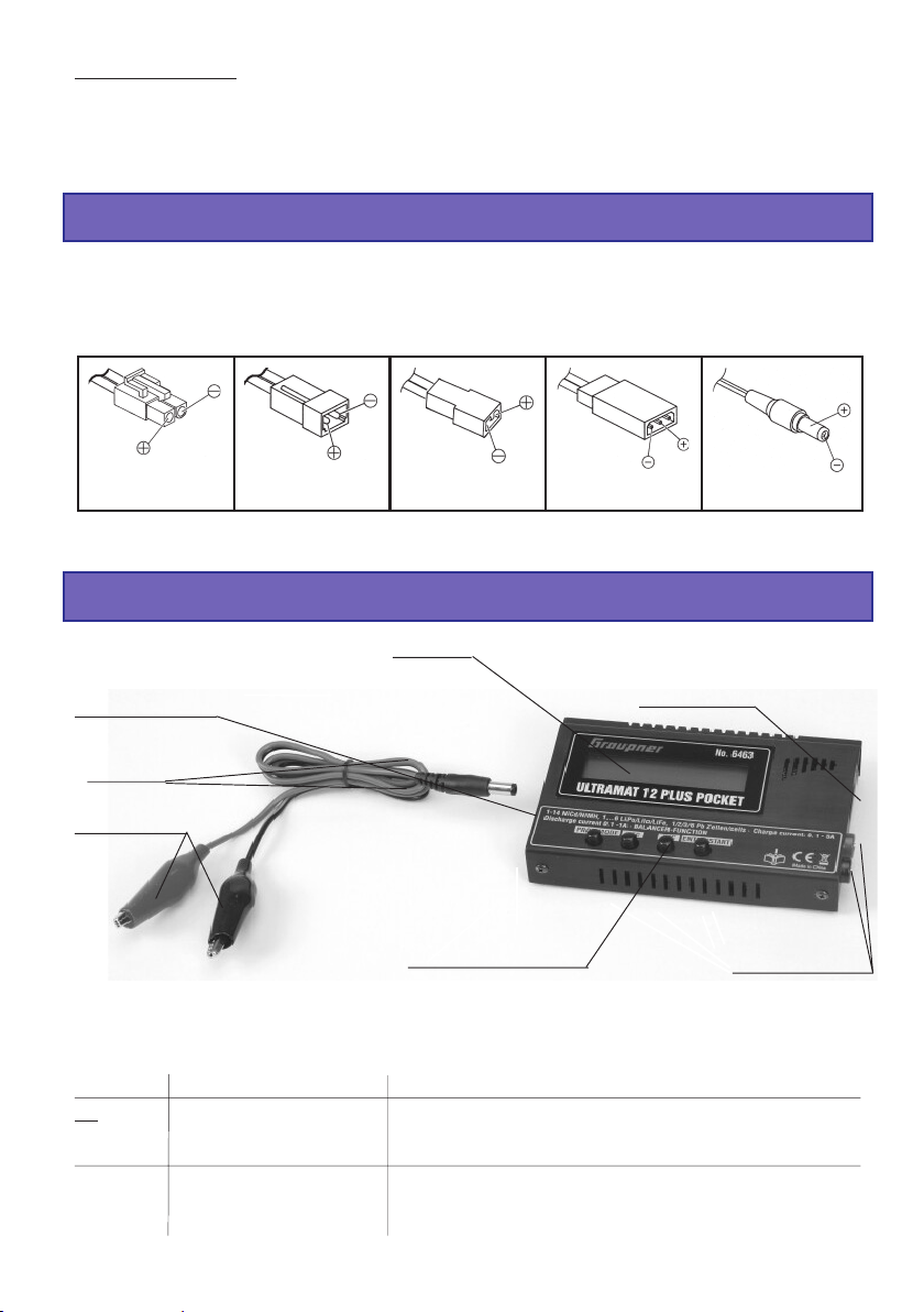
4. Empfohlene Ladekabel / Polaritäten
Verschiedene Anforderungen bei der Verwendung und Einsatz von wiederaufladbaren Akkus machen
auch unterschiedliche Steckverbindungen erforderlich. Beachten Sie, dass Anschlüsse, Bezeichnungen und Polaritäten anderer Hersteller unterschiedlich sein können. Verwenden Sie deshalb immer nur
zueinander passende, Original-Steckverbindungen gleicher Bauart.
Für die Aufladung geeignet sind folgende Ladekabel:
Japan
Best.-Nr. 3371
Verwenden Sie nur Original-Ladekabel mit ausreichendem Drahtquerschnitt.
G2 (AMP/G2,5)
Best.-Nr. 3011
BEC
Best.-Nr. 3037
JR
Best.-Nr. 3021
JR-Sender
Best.-Nr. 3022
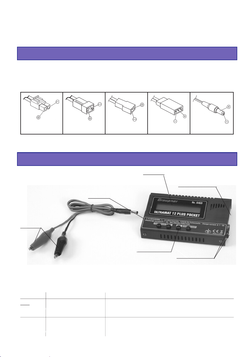
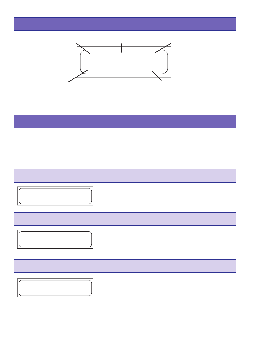
5. Bedienelemente / Bedienung / Ladestart
Anschlussstecker
für Netzgerät #6465
oder
Autobatterie
12V DC
Polklemmen
für Autobatterie
+
-
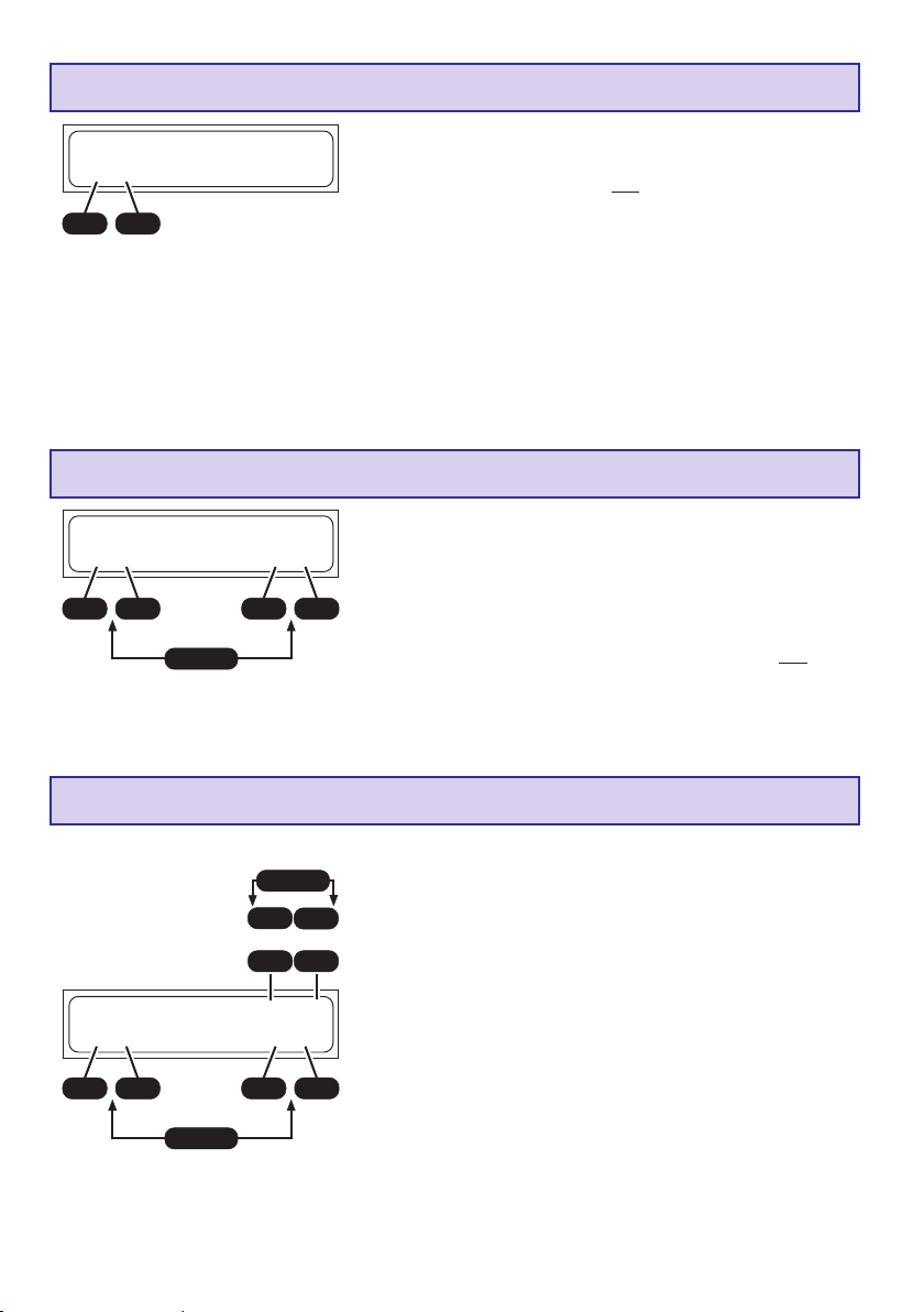
Die Bedienung des Ladegeräts erfolgt durch nur 4 Bedientasten.
Abgesehen von der - /DEC- und +/INC-Taste, mit welcher die Strom- und Spannungswerte verändert
werden, haben die Bedientasten, je nachdem ob am Ladeanschluss ein Akku angeschlossen ist oder
nicht, unterschiedliche Funktionen:
Bedien-Tasten Funktion
Kein Akku PROGRAMM/MODE Auswahl der Ladeprogrammeuntergruppe
angeschl.: PROGRAMM/MODE 2 s. Auswahl der (Lade-)Programm-Gruppe
ENTER/START Bestätigen einer Einstellung im Entlade-/Zyklusmenü
Akku ENTER/START Beenden des Ladevorgangs, Unterbrechen des Summers,
angeschl.: Bestätigen einer Einstellung im Entlade-Zyklusmenü
ENTER/START 2 sek. Starten des Ladevorgangs
Display
Bedientasten
Balancer-Anschluss
für Graupner LiPoBalancerstecker
Ladeanschluss
„Akku “
5
Page 6
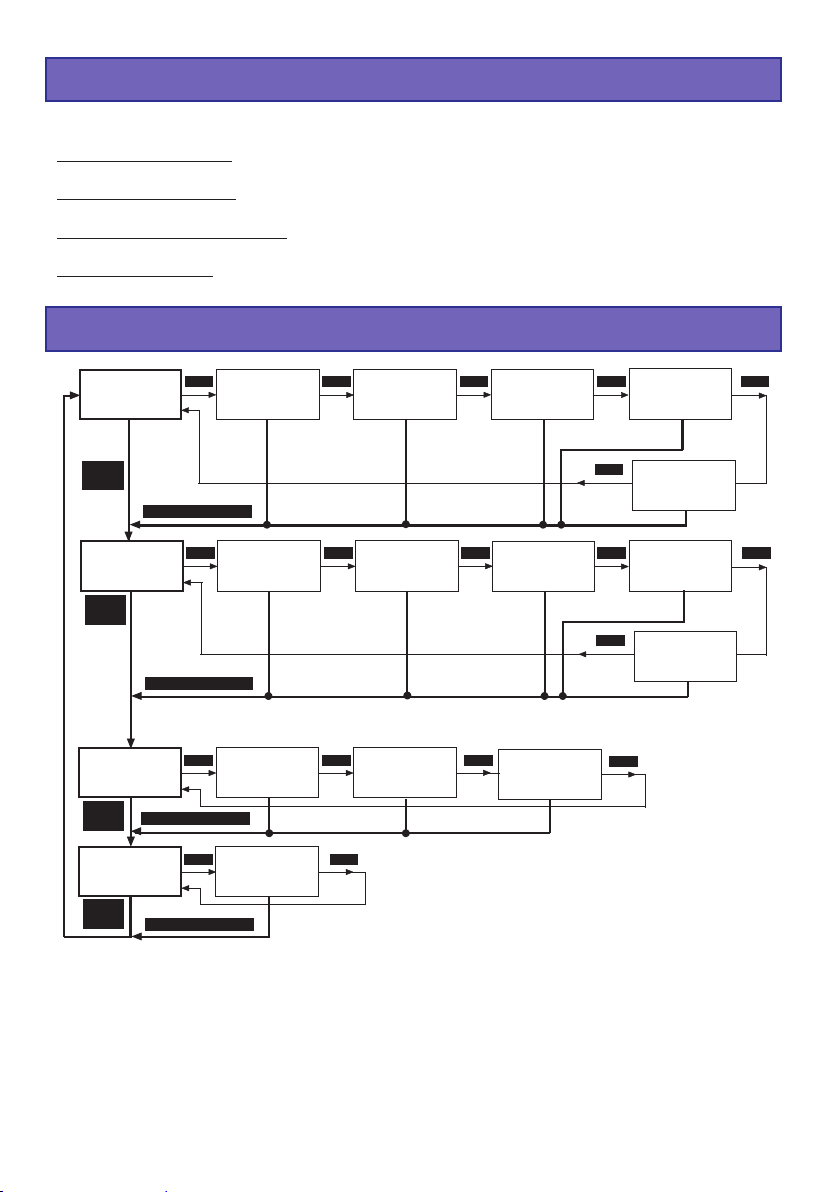
6. Lade- und Entladeprogramme
Die verschiedenen Möglichkeiten des Ladegeräts sind in 4 Programm-Gruppen aufgeteilt, die Sie in
nachfolgend aufgeführter Reihenfolge mit der MODE-Taste (2 sek. drücken) anwählen können.
Ni-Cd-Akku-Programme: Aufladen, Formieren, Entladen zur Ermittlung der Kapazitätsmenge, Restkapazität oder zur Zellenselektion.
Ni-MH-Akku-Programme: Aufladen, Formieren Entladen zur Ermittlung der Kapazitätsmenge, Restkapazität oder zur Zellenselektion.
LiPo/LiIo/LiFe-Akku-Programme: Aufladen, Entladen zur Ermittlung der Kapazitätsmenge, Restkapazität
oder zur Zellenselektion.
Blei-Akku-Programme: Aufladen, Entladen zu Ermittlung der Kapazitätsmenge oder Restkapazität,
Erhaltungsladung für Stand by Betrieb.
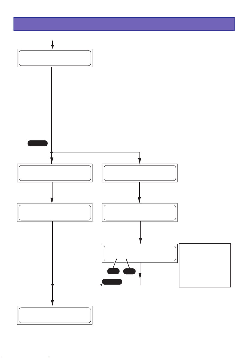
7. Programmstruktur
NiCd
AUTOMATIK-
Programm
MODE
(2 sek.)
NiMH
AUTOMATIK-
Programm
MODE
(2 sek.)
Lithium
MANUELLProgramm
MODE
(2 sek.)
Pb
MANUELLProgramm
MODE
(2 sek.)
MODE MODE MODE MODE MODE
MODE (2 sek.)
MODE MODE MODE MODE MODE
MODE (2 sek.)
MODE MODE MODE
MODE (2 sek.)
MODE MODE
MODE (2 sek.)
NiCd
MANUELL-
Programm
NiMH
MANUELL-
Programm
Lithium
Entladeprogramm
Pb
Entladeprogramm
NiCd
Entladeprogramm
NiMH
Entladeprogramm
Lithium
Lagerprogramm
NiCd
Formierungs-
programm
NiMH
Formierungs-
programm
Lithium
Typen-
Auswahl
MODE
MODE
NiCd
Entladebalancier-
programm
NiCd
∆ ∆
∆
delta-peak
∆ ∆
Abschaltspannung
NiMH
Entladebalancier-
programm
NiMH
∆ ∆
∆
delta-peak
∆ ∆
Abschaltspannung
MODE
6
Page 7
8. Auswahl der Ladeprogrammgruppe
NiCd
AUTOMATIK
Programm
MODE (2
NiMH
AUTOMATIK
Programm
MODE (2
Lithium
MANUELL
Programm
MODE (2
Pb
MANUELL
Programm
MODE (2
sek.)
sek.)
sek.)
sek.)
Die Lade- und Einstellmöglichkeiten des Ladegerätes sind übersicht-
MODE
lich und logisch in vier Programmgruppen unterteilt.
Für die unterschiedlichen Akkutypen: NickelCadmium-, Nickel-MetalHydrid-, LiFe/LitiumIonen/LithiumPolymer und Pb (Blei)-Akkus steht
jeweils eine eigene Programmgruppe zur Verfügung.
MODE
Programmwechsel:
Der Wechsel der Programm-Gruppe erfolgt mit der Taste MODE,
MODE
die für ca. 2 Sekunden gedrückt werden muss. Mit einem Kurzdruck
der MODE Taste können Sie innerhalb der Programm-Gruppe wechseln.
MODE
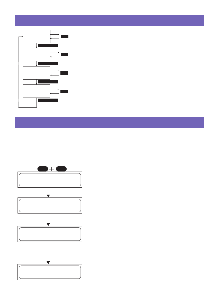
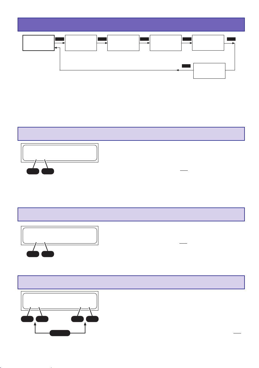
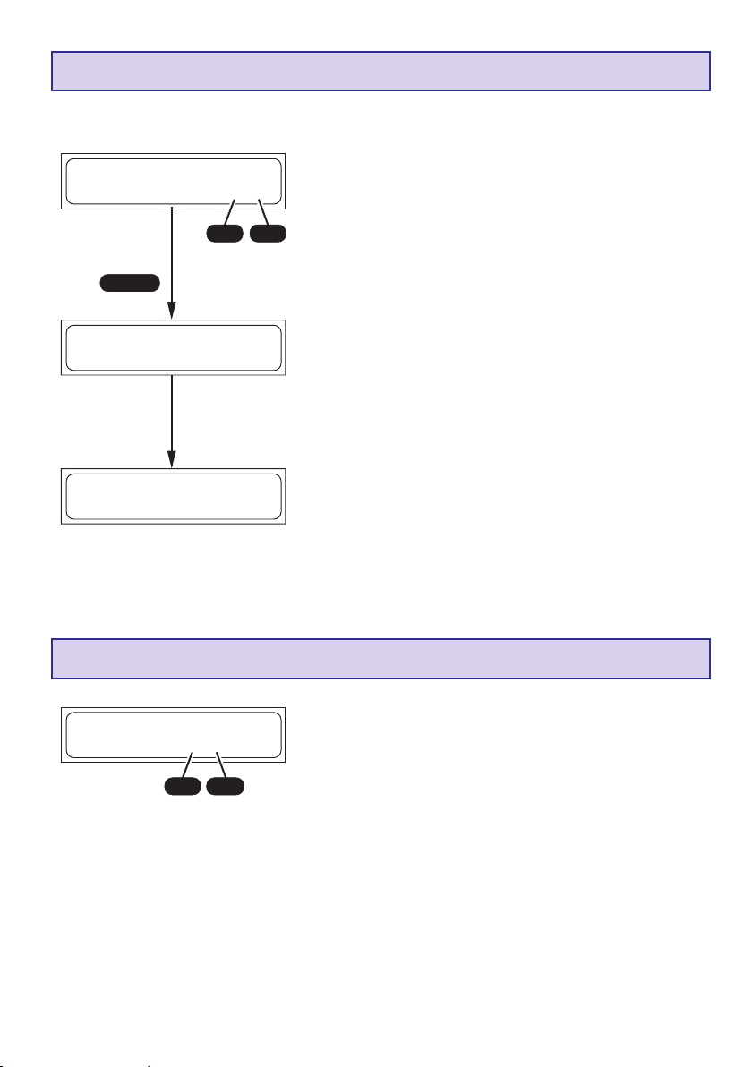
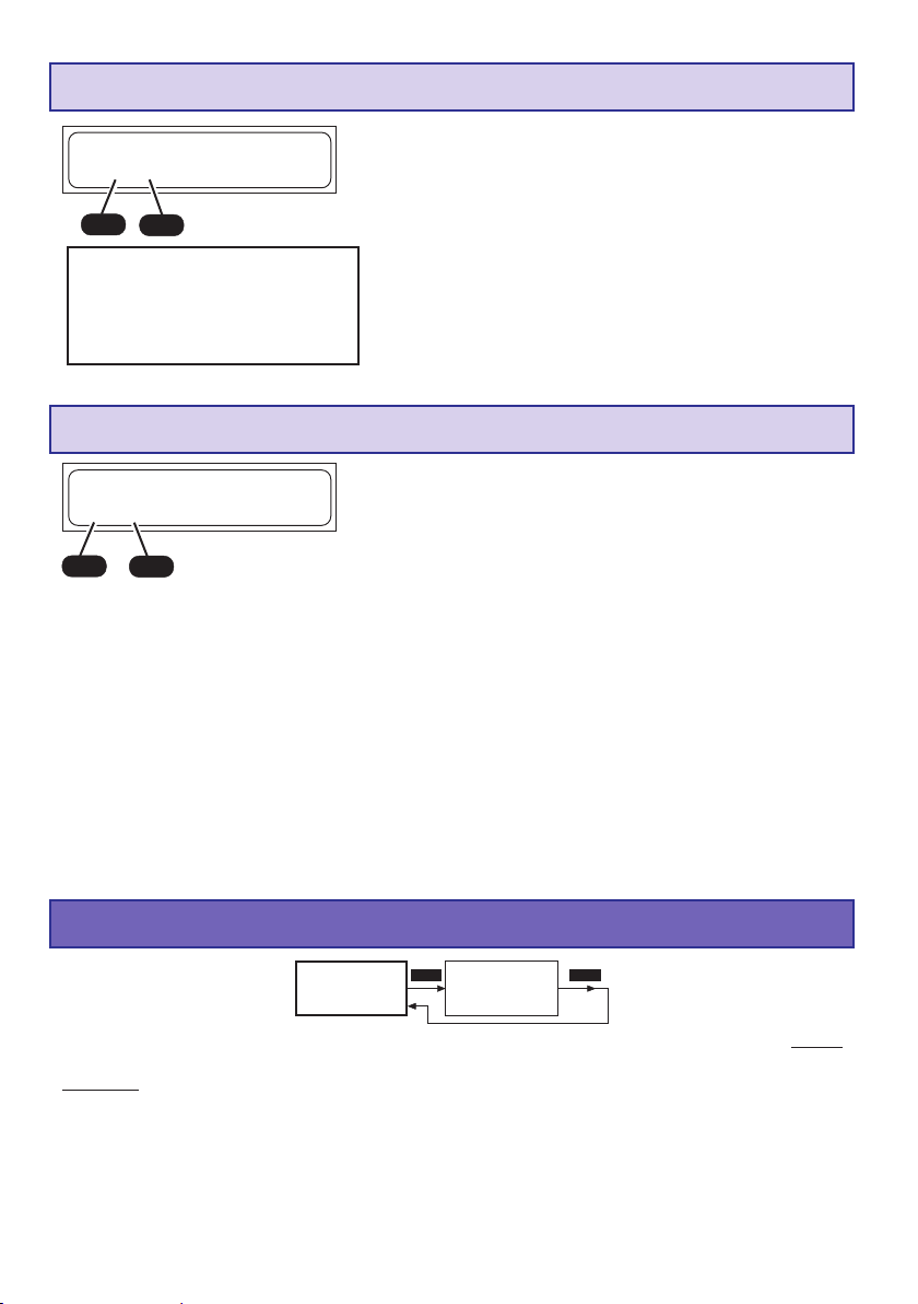
9. Inbetriebnahme
Wird das Ladegerät am Eingang 12V DC mit einer Autobatterie oder einem Netzteil mind. 5A mit 11...15V
DC verbunden, drücken Sie die Tasten INC und DEC gleichzeitig, um in die Sprachauswahl zu gelangen.
Ansonsten läuft zunächst die Informationsroutine ab, welche einen schnellen Überblick über die
wichtigsten Benutzer-Einstellungen des Ladegerätes gibt. Auf dem Display des Ladegeräts werden
nacheinander folgende Informationen angezeigt:
DECINC
________________
LANGUAGE SELECT
GERMAN
________________
ENTER
Drücken Sie die Tasten INC und DEC gleichzeitig, während Sie
das Gerät mit der Eingangsspannung versorgen, um in die
Sprachauswahl zu gelangen. Drücken Sie die Tasten INC oder
DEC um die gewünschte Sprache ENGLISH, GERMAN
(Deutsch) oder FRENCH auszuwählen. Verlassen Sie die
Sprachauswahl mit indem Sie die Taste ENTER drücken.
________________
Graupner V1.00
U12 PLUS POCKE T
________________
3 sek.
________________
Sicherheitstimer
90min
________________
3 sek.
________________Summer
10Sek
________________
Der ULTRAMAT 12 PLUS meldet sich mit seinem Namen.
Nach 3 Sekunden erscheint das im Display Sicherheitstimer
ein oder aus. Etwa 3 Sekunden lang lässt sich der Sicherheitstimer mit den Tasten INC oder DEC einstellen.
(10min...300min/aus)
Der Sicherheitstimer ist beim Entladen oder im Pb-Ladeprogramm niemals aktiv.
Nach weiteren 3 Sekunden lässt sich der Summer mit den INCoder DEC-Tasten einstellen. (ein, 3...10s, aus)
Nach weiteren 3 Sek. ist das Ladegerät einsatzbereit, s. 10..
7
Page 8
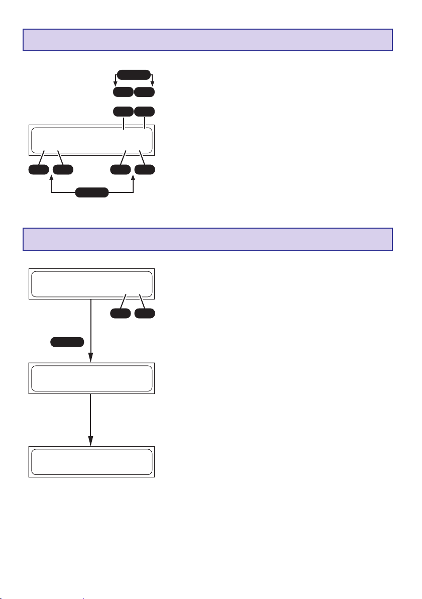
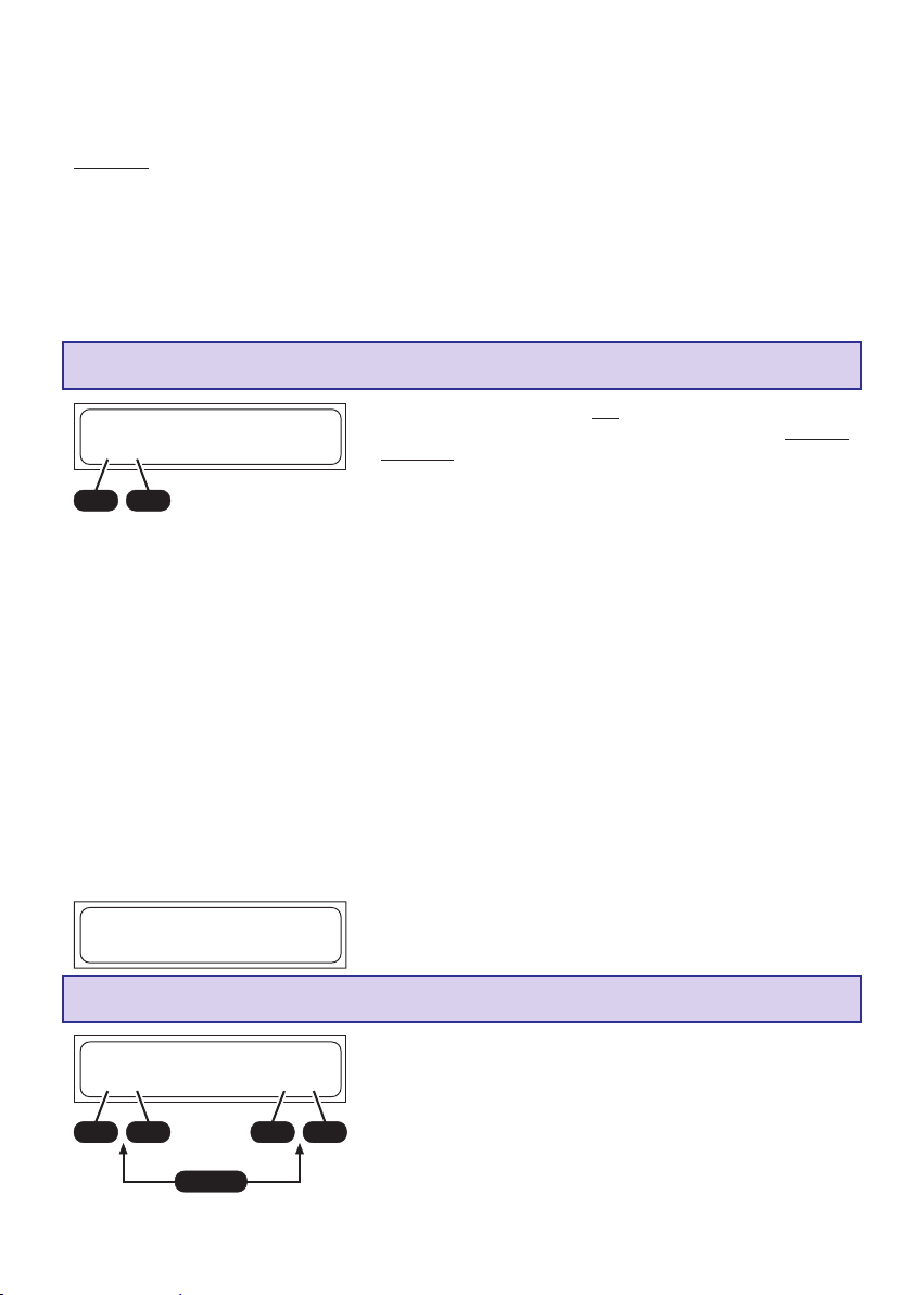
10. Starten des Lade- Entladevorgangs
3 sek.
________________LiPo-Manuell
L:2.5A 2 000mAh
________________
START
________________**INFORMATION***
BALANCER ANG.
________________
________________VERMESSE AKKU
BITTE WARTEN...
________________
2 sek.
2 sek.
2 sek.
Zum Laden-Entladen bzw. Formieren, wählen Sie das gewünschte Programm wie nachfolgend beschrieben aus und
stellen die passenden Werte dazu ein.
Schließen Sie, wenn vorhanden, den Balancerstecker des
Akkus an den Balancereingang (BALANCER CONNECTOR)
an.
Achten Sie dabei auf die richtige Polung.
Von rechts nach links: (Pin 1 (GND): Masse = Akku - ,
Pin 2 (1): + Zelle 1, Pin 3 (2): + Zelle 2, Pin 4 (3): + Zelle 3,
Pin 5 (4): + Zelle 4, Pin 6 (5): + Zelle 5, Pin 7 (6): + Zelle 6)
Schließen Sie dann den 2 pol. Anschlussstecker des Akkus an
den Ladegerätausgang - BATTERY + richtig gepolt mit Hilfe
eines Ladekabels an.
Nachdem Sie für ca. 2sek. die START-Taste gedrückt halten
wird angezeigt, ob der Balancer angeschlossen oder nicht
angeschlossen ist. Bei angeschlossenem Balancer können die
einzelnen Zellenspannungen angezeigt werden, s. 16..
________________**INFORMATION***
BALANCER N. ANG.
________________
2 sek.
________________VERMESSE AKKU
BITTE WARTEN...
________________
2 sek.
________________
**LiPo Zellen**
3 Zellen(13.73V)
________________
+
INC
DEC
START
Nachdem Sie die START-Taste erneut drücken wird der angeschlossene Akku geladen oder entladen.
Ist bei Li-Akkutypen kein Balancerstecker
angeschlossen, so erfolgt die Abfrage der
Zellenzahl, die mit der START- Taste bestätigt werden muss.
!Achtung ! Stellen Sie
unbedingt die Richtige
Zellenzahl ein und
-
überprüfen Sie den
Akkutyp, da sonst der
Akku explodieren und
brennen könnte!
________________Man. 23:40 00863
LP+2.50A 14.017V
________________
8
Durch einen erneuten kurzen Druck auf die START-Taste
können Sie den Ladevorgang jederzeit abbrechen.
Hinweis: Wird der Ladevorgang mit der START-Taste abgebrochen, so sind alle Displayparameter unwiderruflich
gelöscht.
Page 9
11. NiCd-Programme
NiCd
AUTOMATIK-
Programm
MODE MODE MODE MODE MODE
NiCd
MANUELL-
Programm
NiCd
Entladeprogramm
NiCd
Formierungs-
programm
MODE
NiCd
Entladebalancier-
programm
NiCd
∆ ∆
∆
delta-peak
∆ ∆
Abschaltspannung
Komfortable Ladeprogramme für die Aufladung von im Modellbau üblichen Nickel-Cadmium-Akkus.
Ist das Lade-/Entlade-Programm beendet, so erscheint bis zum Abklemmen des Akkus das Ladeprogramm abwechselnd mit dem Schriftzug “*ENDE*” im Display, die Ladezeit, der letzte (Ent-)/
Ladestrom, die ge(ent-)ladene Kapazität sowie Akkuspannung werden angezeigt. Diese Daten geben
unter Umständen wertvolle Hinweise auf das Ladeverhalten, die Kapazität des angeschlossenen Ni-Cd
Akku-Packs oder fehlerhafte Vollerkennung.
NiCd-Automatik-Programm
________________NiCd-Automatik
L:2.5A begrenzt
________________
+
-
DECINC
In diesem Programm erkennt das Ladegerät den angeschlossenen Ni-Cd Akkutypen und passt den Ladestrom dementsprechend an, sodass eine Überlastung des Akkupacks verhindert
wird.
Der maximale Ladestrom muss vor dem Anstecken des zu
ladenden Akkus mit den INC / DEC-Tasten von 0,1A -5,0A bzw.
ohne Begrenzung so eingestellt werden, dass der max. zulässige Ladestrom des Akkus nicht überschritten werden kann.
Die Ladeabschaltung erfolgt nach den eingestellten Werten für
„NiCd-Delta-Peak-Abschaltspannung“.
NiCd-Manuell-Programm
________________NiCd-Manuell
L:2.5A
________________
+
-
DECINC
________________NiCd-Entladen
1.00A 4.8V
________________
+
-
DECINC
+
INC
DEC
ENTER
Bei diesem Programm wird der Akku mit dem eingestellten
Ladestrom aufgeladen.
Der maximale Ladestrom kann vor dem Anstecken des zu
ladenden Akkus mit den INC / DEC-Tasten von 0,1A -5,0A
eingestellt werden. Beachten Sie die Angaben des Akkuherstellers!
Die Ladeabschaltung erfolgt nach den eingestellten Werten für
„NiCd-Delta-Peak-Abschaltspannung“.
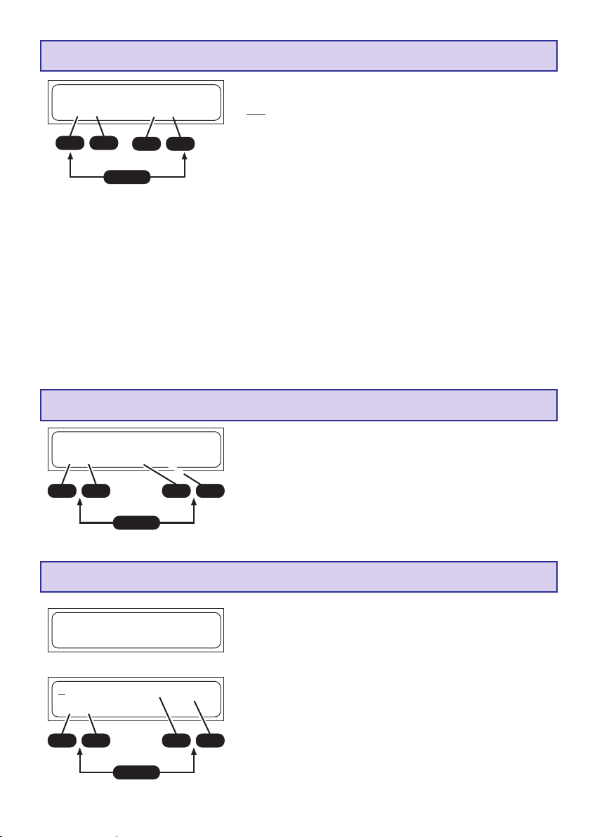
NiCd-Entlade-Programm
Dieses Programm dient z.B. zur Feststellung der Restkapazität
oder zur definierten Entladung eines Sender-, Empfänger oder
Antriebsakkus
Bei diesem Programm wird mit dem eingestellten Entladestrom
-
(0,1...1,0A, links im Display) bis zur eingestellten Entladeschlußsspannung (0.1...16,8V, rechts im Display) entladen.
Als Entladeschlussspannungen sollten etwa 0,9 ... 1,1 V pro
Zelle gewählt werden um die Akkus nicht zu weit zu entladen
und eine evtl. Zellen-Umpolung zu verhindern.
9
Page 10
NiCd-Formierungs-Programm
ENTER
INC
oder
DEC
________________NiCd Zykl. L>E 1
L:2.5A E:1.00A
________________
+
INC
-
DEC
ENTER
+
INC
NiCd-Entladebalancier-Programm
________________NiCd Balancer-
spannung = 1.20V
________________
+
INC
START
________________**INFORMATION***
BALANCER ANG.
________________
2 sek.
2 sek.
INC
DEC
DEC
DEC
Dieses Programm dient zur Optimierung von Kapazität und
Formierung einer Batterie.
Mit der INC oder DEC Taste stellen Sie oben rechts ein, ob das
Formierungsprogramm mit dem Laden oder Entladen beginnen soll. Anschließend stellen Sie die Zyklenzahl von 1-5 ein
(Bei z.B. 3 Zyklen wird der Akku dreimal geladen und entladen).
Das Programm entlädt den Akku mit dem rechts im Display
eingestellten Entladestrom (0,1...1,0A) um ihn anschließend
mit dem links im Display eingestellten Ladestrom (0,1...5,0A)
wieder aufzuladen.
Die Lade-Abschaltung erfolgt nach den in den Einstellungen
-
für „NiCd-Delta-Peak-Abschaltspannung“.
Die Entlade-Abschaltung erfolgt nach der im NiCd-EntladeProgramm eingstellten Entladeschlussspannung.
Das Auslesen des aktuellen Zyklenwertes ist im Abschnitt
„Displayanzeigen“ beschrieben.
Dieses Programm dient zur Angleichung der Zellenspannungen
der einzelnen Akkuzellen für Akkupacks mit 2-6 Zellen.
Mit der INC oder DEC Taste stellen Sie die
Balancerentladeschlussspannung 1.20...1.30V ein.
Vor dem Laden eines Akkus sollten die einzelnen Zellen
-
angeglichen werden, damit beim Laden nicht einzelne Zellen
überladen werden. Besonders nach einer längeren Lagerzeit
sollte ein Akku ausbalanciert werden.
Dazu muss der Balancerstecker angeschlossen sein.
Weiterhin müssen alle Zellen eine Spannung aufweisen, die
höher ist, als die eingestellte Balancerentladeschlussspannung.
Um die max. Kapazität eines Akkus zu erhalten, sollten die
einzelnen Zellen einige Stunden, aber max. 24h vor der erneuten Ladung auf 1.20V entladen werden. Bei einer Spannung
unter 1.20V verlieren die Akkuzellen an Kapazität. Deshalb
muss ein Akku vor einer längeren Lagerung mit etwa 60%
Ladung gelagert werden.
Entl
________________BLC 28:30 01425
Entl
NC-3.00A 06.717V
________________
10
Das Programm entlädt den Akkupack mit 50mA...1,0A. Zellen
mit einer höheren Zellenspannung werden zusätzlich mit einem Strom von ca. 100mA entladen (ausbalanciert).
Haben alle Zellen die Balancerentladeschlussspannung
(+0.01V) erreicht, so wird der Entladebalanciervorgang beendet.
Page 11
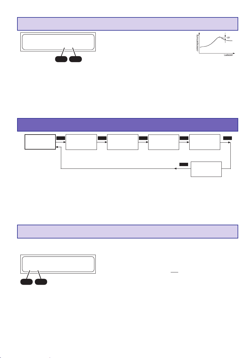
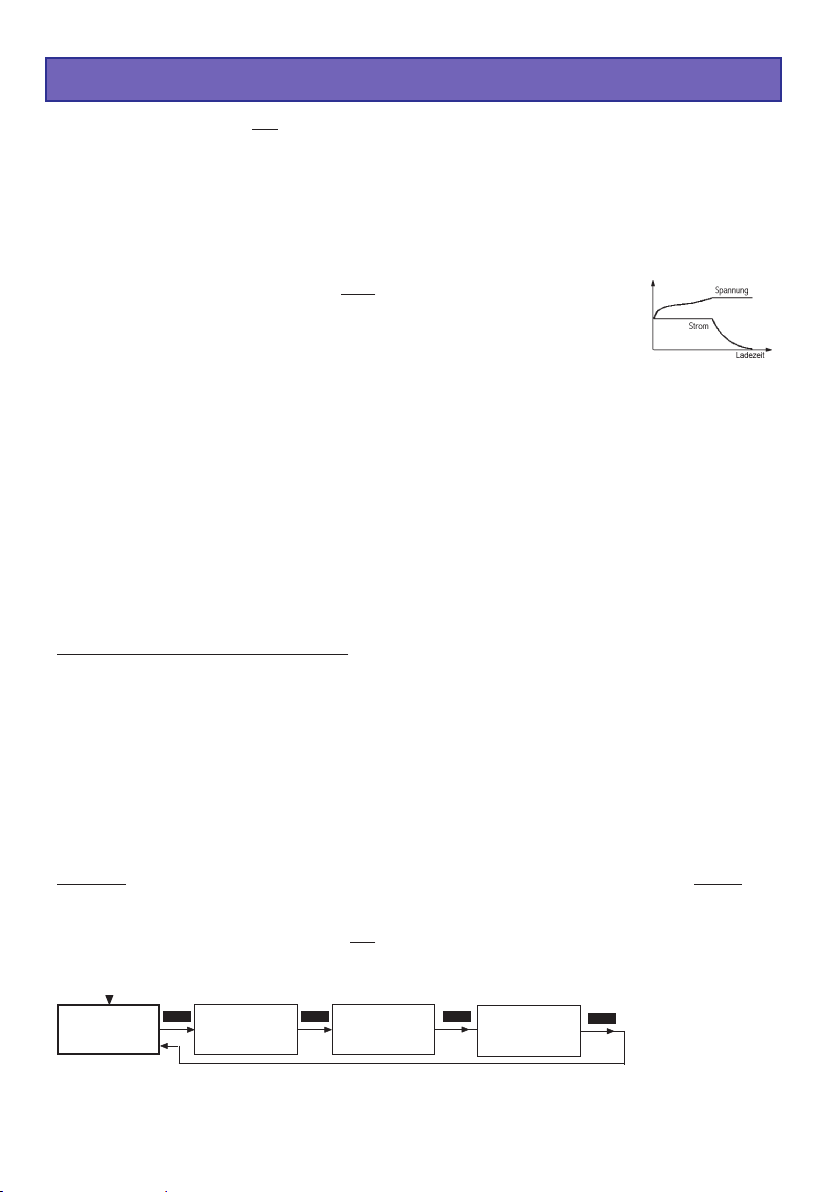
NiCd-Delta-Peak (-
________________NiCd Delta-Peak-
Volt =10mV/Zelle
________________
+
-
DECINC
∆∆
∆ Peak)
∆∆
Abschaltspannung
Die Ladeabschaltautomatik (Akku-Vollerkennung) arbeitet nach dem millionenfach bewährten Delta-Peak-Verfahren
(auch bekannt als Delta-U- oder Delta-VVerfahren). Dieses Verfahren wertet das
Spannungsmaximum der Ladekurve aus, welches recht genau
das Erreichen des maximalen Ladungsinhaltes angibt.
Während der Ladung steigt die Akkuspannung zunächst kontinuierlich an, bei vollem Akku sorgt die
Temperaturerhöhung wieder für einen leichten Rückgang (-∆V) der Batteriespannung. Dieser Rückgang
wird ermittelt und ausgewertet.
Die Abschaltspannung (in mV pro Zelle!) der Abschaltautomatik für NiCd-Akkus kann eingestellt werden.
Als praktikabel haben sich Spannungen von 10...30 mV/Zelle herausgestellt. Höhere Spannungen
führen häufig zur Überladung der Batterie, niedrigere Spannungen führen oft zu Frühabschaltung. Den
für Ihren Akku günstigsten Wert sollten Sie durch Probeladungen ermitteln.
Um dem Akku nicht zu überladen, beginnen Sie mit einer Delta-Peak-Abschaltspannung von 10mV.
12. NIMH-Programme
NiMH
AUTOMATIK-
Programm
NiMH
MODE MODE MODE MODE MODE
MANUELL-
Programm
NiMH
Entladeprogramm
NiMH
Formierungs-
programm
Entladebalancier-
MODE
Abschaltspannung
NiMH
programm
NiMH
∆ ∆
∆
delta-peak
∆ ∆
Komfortable Ladeprogramme für die Aufladung von im Modellbau üblichen Nickel-Metall-Hydrid-Akkus.
Ist das Lade-/Entlade-Programm beendet, so erscheint bis zum Abklemmen des Akkus das Ladeprogramm abwechselnd mit dem Schriftzug “*ENDE*” im Display, die Ladezeit, der letzte (Ent-)/
Ladestrom, die
ge(ent-)ladene Kapazität sowie Akkuspannung werden angezeigt. Diese Daten geben unter Umständen
wertvolle Hinweise auf das Ladeverhalten, die Kapazität des angeschlossenen Ni-MH- Akku-Packs oder
fehlerhafte Vollerkennung.
NiMH-Automatik-Programm
In diesem Programm erkennt das Ladegerät den angeschlossenen Ni-Mh Akkutypen und passt den Ladestrom dementsprechend an, sodass eine Überlastung des Akkupacks verhin-
________________ NiMH-Automatik
L:2.5A begrenzt
________________
+
INC
-
DEC
dert wird.
Der maximale Ladestrom muss vor dem Anstecken des zu
ladenden Akkus mit den INC / DEC-Tasten von 0,1A -5,0A bzw.
ohne Begrenzung so eingestellt werden, dass der max. zulässige Ladestrom des Akkus nicht überschritten werden kann.
Laden Sie die Akkus auf keinen Fall mit mehr als 2C!
Bsp.: NiMH 6N-4200, max. Ladestrom 8,4A, empfohlener
Schnellladestrom für Graupner-Akkus 4,2A.
Senderakkus müssen auf max. 2A Ladestrom begrenzt werden! Beachten Sie auch die Anleitungen bzw. den max. Ladestrom des Senders und des Senderakkus!
Die Ladeabschaltung erfolgt nach den eingestellten Werten für
„NiMH-Delta-Peak-Abschaltspannung“.
11
Page 12
NiMH-Manuell-Programm
________________NiMH-Manuell
L:2.5A
________________
+
+
-
DECINC
________________NiMH-Entladen
1.00A 4.8V
________________
-
DECINC
ENTER
+
Bei diesem Programm wird der Akku mit dem eingestellten
Ladestrom aufgeladen.
Der maximale Ladestrom kann vor dem Anstecken des zu
ladenden Akkus mit den INC / DEC-Tasten von 0,1A - 5,0A
eingestellt werden. Beachten Sie die Angaben des Akkuherstellers! Laden Sie die Akkus auf keinen Fall mit mehr als 2C!
Bsp.: NiMH 6N-4200, max. Ladestrom 8,4A, empfohlener
Schnellladestrom für Graupner-Akkus 4,2A.
Senderakkus müssen auf max. 2A Ladestrom begrenzt werden! Beachten Sie auch die Anleitungen bzw. den max. Ladestrom des Senders und des Senderakkus!
Die Ladeabschaltung erfolgt nach den eingestellten Werten für
„NiMH-Delta-Peak-Abschaltspannung“.
NiMH-Entlade-Programm
Dieses Programm dient z.B. zur Feststellung der Restkapazität
oder zur definierten Entladung eines Sender-, Empfänger oder
Antriebsakkus
-
Bei diesem Programm wird mit dem eingestellten Entladestrom
DECINC
(0,1...1,0A, links im Display) bis zur eingestellten Entladeschlussspannung (0.1...16,8V, rechts im Display) entladen.
Als Entladeschlussspannungen sollten etwa 1,1 ... 1,2 V pro Zelle
gewählt werden um die Akkus nicht zu weit zu entladen und eine
evtl. Zellen-Umpolung zu verhindern.
NiMH-Formierungs-Programm
ENTER
INC
oder
DEC
________________NiMH Zykl. L>E 1
L:2.5A E:1.00A
________________
12
+
INC
-
DEC
ENTER
+
INC
Dieses Programm dient zur Optimierung von Kapazität und
Formierung einer Batterie.
Mit der INC oder DEC Taste stellen Sie oben rechts ein, ob das
Formierungsprogramm mit dem Laden oder Entladen beginnen
INC
soll. Anschließend stellen Sie die Zyklenzahl von 1-5 ein (bei z.B.
3 Zyklen wird der Akku dreimal geladen und entladen). Das
DEC
Programm entlädt den Akku mit dem rechts im Display eingestellten Entladestrom (0,1...1,0A) um ihn anschließend mit dem links
im Display eingestellten Ladestrom (0,1...5,0A) wieder aufzuladen.
Die Lade-Abschaltung erfolgt nach den in den Einstellungen für
-
„NiMH-Delta-Peak-Abschaltspannung“.
DEC
Die Entlade-Abschaltung erfolgt nach der im NiMH-EntladeProgramm eingstellten Entladeschlussspannung.
Das Auslesen des aktuellen Zyklenwertes ist im Abschnitt „Displayanzeigen“ beschrieben.
Page 13
NiMH-Entladebalancier-Programm
________________NiMH Balancer-
spannung = 1.20V
________________
+
INC
DEC
START
________________**INFORMATION***
BALANCER ANG.
________________
2 sek.
2 sek.
Dieses Programm dient zur Angleichung der Zellenspannungen
der einzelnen Akkuzellen für Akkupacks mit 2-6 Zellen.
Mit der INC oder DEC Taste stellen Sie die
Balancerentladeschlussspannung 1.20...1.30V ein.
Vor dem Laden eines Akkus sollten die einzelnen Zellen
-
angeglichen werden, damit beim Laden nicht einzelne Zellen
überladen werden. Besonders nach einer längeren Lagerzeit
sollte ein Akku ausbalanciert werden.
Dazu muss der Balancerstecker angeschlossen sein.
Weiterhin müssen alle Zellen eine Spannung aufweisen, die
höher ist, als die eingestellte Balancerentladeschlussspannung.
Um die max. Kapazität eines Akkus zu erhalten, sollten die
einzelnen Zellen einige Stunden, aber max. 24h vor der erneuten Ladung auf 1.20V entladen werden. Bei einer Spannung
unter 1.20V verlieren die Akkuzellen an Kapazität. Deshalb
muss ein Akku vor einer längeren Lagerung mit etwa 60%
Ladung gelagert werden.
Entl
________________BLC 28:30 01425
Entl
NM-3.00A 06.717V
________________
NiMH-Delta-Peak (-
________________NiMH Delta-Peak-
Volt =10mV/Zelle
________________
+
-
DECINC
Das Programm entlädt den Akkupack mit 50mA...5,00A. Zellen
mit einer höheren Zellenspannung werden zusätzlich mit einem Strom von ca. 100mA entladen (ausbalanciert).
Haben alle Zellen die Balancerentladeschlussspannung
(+0.01V) erreicht, so wird der Entladebalanciervorgang beendet.
∆∆
∆ Peak)
∆∆
Die Ansprechspannung (in mV pro Zelle!) der Abschaltautomatik für NiMH-Akkus kann eingestellt werden. NiMHAkkus haben gegenüber NiCd-Akkus einen weniger ausgeprägten Spannungsrückgang. Als praktikabel haben sich
Spannungseinstellungen von 5 ... 25mV/Zelle herausgestellt.
Höhere Spannungen führen häufig zur Überladung der
Batterie, niedrigere Spannungen führen oft zu Frühabschaltung.
Den für Ihren Akku günstigste Wert sollten Sie durch Probeladungen ermitteln. Beginnen Sie mit 5mV/Zelle, um den Akku
nicht zu überladen.
Ansprechspannung
13
Page 14
13. Lithium-Programme
Die Ladeprogramme sind nur zum Laden und Entladen von LiFePO4 (LiFe) -Akkus mit einer
Zellenspannung von 3,3 V/Zelle, Lithium Ionen-Akkus mit einer Zellennennspannung von 3,6 V/Zelle,
Lithium Polymer- und Lithium Mangan-Akkus mit einer Zellen Nennspannung von 3,7 V/Zelle geeignet.
Lithium-Akkus zeichnen sich vor allem durch ihre, im Vergleich zu anderen Akkutypen, wesentlich
höhere Energiedichte aus. Dieser wesentliche Vorteil auf der einen Seite erfordert jedoch andere
Behandlungsmethoden in Bezug auf die Ladung / Entladung sowie für einen gefahrlosen Betrieb.
Die hier grundlegenden Vorschriften müssen auf alle Fälle beachtet werden. Weitere entsprechende
Angaben und Sicherheitshinweise entnehmen sie bitte den technischen Angaben des Akkuherstellers.
Prinzipiell können Akkus auf Lithiumbasis NUR mit speziellen Ladegeräten geladen
werden, die auf den jeweiligen Akkutyp (Ladeschlussspannung, Kapazität)
eingestellt sind.Die Aufladung erfolgt anders als bei NiCd- oder NiMH-Akkus durch
eine sog. Konstantstrom/Konstantspannungs-Methode. Der für die Ladung
erforderliche Ladestrom ergibt sich aus der Akkukapazität und wird vom Ladegerät
automatisch eingestellt. Lithiumakkus werden gewöhnlich mit 1 C Ladestrom aufgeladen (1 C Ladestrom
= Kapazitäts-Ladestrom. Beispiel: Bei einer Kapazität von z. B.: 1500 mAh ist der entsprechende 1 C
Ladestrom = 1500 mA (1,5A)).
Da manche Zellentypen auch 2C oder 4C zulassen, muss am Ladegerät der Ladestroms und die
Kapazität des Akkus eingestellt werden. Wird die zum jeweiligen Akkutyp gehörende, spezifische
Ladeschlussspannung erreicht, wird der Ladestrom automatisch reduziert, um ein Überschreiten der
Ladeschlussspannung zu verhindern.Gibt der Akku-Hersteller einen kleineren als den 1 C Ladestrom an,
so muss auch der Ladestrom entsprechend verringert werden.
Für eine optimale Ladung und eine höhere Lebensdauer und eine höhere Sicherheit bei der
Ladung empfehlen wir dringend den Balancerstecker beim Laden und Entladen an das Ladegerät
anzuschließen.
Probleme bei Fehlbehandlung der Akkus:
Lithium-Ionen-Akkus sind durch Überladung stark gefährdet. Sie kann zu Gasentwicklung, Überhitzung
und sogar zur Explosion der Zelle führen. Wird die Ladeschlussspannung von 3,6 V/Zelle (LiFePO4),
4,1 V/Zelle (Lithium Ionen) bzw. 4,2 V/Zelle (Lithium Polymer und Mangan) um mehr als 1% überschritten, so beginnt in der Zelle die Umwandlung der Lithium-Ionen in metallisches Lithium. Dieses reagiert
jedoch in Verbindung mit Wasser aus dem Elektrolyten sehr heftig, was zur Explosion der Zelle führt.
Andererseits darf die Ladeschlussspannung aber auch nicht unterschritten werden, da die Li IonenAkkuzelle sonst eine deutlich geringere Kapazität aufweist. 0,1V unter der Schwelle bedeuten bereits
etwa 7% Kapazitätsverlust.Tiefentladung von Lithium-Akkus führt zum rapiden Kapazitätsverlust. Dieser Effekt ist nicht umkehrbar, sodass man es auf jeden Fall vermeiden muss, den Akku unter 2,5 V/
Zelle zu entladen.
Achtung: Der eingestellte Zellentyp, die Zellenkapazität und die Zellenanzahl muss immer mit
dem zu ladenden Akku übereinstimmen und darf niemals abweichen - Brandgefahr und
Explosionsgefahr! Es dürfen keine Akkus mit integrierten Lademechanismen angeschlossen
werden! Laden Sie Ihre Lithium-Akkus nur auf brandsicherem Untergrund.
Lithium
MANUELLProgramm
Lithium
MODE MODE MODE
Entladeprogramm
Lithium
Lagerprogramm
Lithium
Typen-
Auswahl
MODE
14
Page 15
Lithium-Manuell-Programm
________________LiPo-Manuell
L:4.0 A 4000mAh
________________
+
INC
Beim Laden wird der Anschluss des Balancersteckers aus Sicherheitsgründen dringend empfohlen!
Wird der Akku anschließend an das Ladegerät angeschlossen und der Ladevorgang gestartet, so
beginnt der Ladestrom von 0,00 A an langsam bis an die eingestellte Begrenzung anzusteigen.
Wundern Sie sich jedoch nicht, wenn der von Ihnen eingestellte Ladestrom nicht erreicht wird, denn das
Ladeprogramm überwacht ständig die Batteriespannung und verhindert so ein aufblähen des Akkus,
solange die Spannungen der Zellen eines Akkupacks gleich sind. Bei angeschlossenem Balancerstecker
werden die einzelnen Akkuzellen automatisch angeglichen.
Der Ladestrom wird automatisch reduziert, wenn die Entladeschlussspannung einer Zelle erreicht ist.
Beträgt der Ladestrom etwa 1/10 des eingestellten Stromwertes, so wird der Ladevorgang beendet und
wird im Display durch den Schriftzug „ENDE.“ abwechselnd mit dem Ladestrom angezeigt.
DEC
-
ENTER
+
INC
-
DEC
Bei diesem Programm wird der Akku mit dem eingestellten
Ladestrom aufgeladen.
Vor dem Anstecken des zu ladenden Akkus wird mit den INC
/ DEC-Tasten der Ladestrom (0,1...5,0A, links im Display) und
nach dem Drücken der ENTER-Taste wird mit den INC / DECTasten die Kapazität des Akkus eingestellt (50 ... 9900mAh,
rechts im Display). Bei Überschreitung der eingestellten Kapazität um 10% wird der Ladevorgang aus Sicherheitsgründen
abgebrochen.
Lithium-Entlade-Programm
________________LiPo-Entladen
1.00A 2.5V/Zelle
________________
+
INC
-
DEC
ENTER
+
DECINC
Dieses Programm dient z.B. zum Feststellen der Restkapazität
eines noch nicht leeren Lithiumakkus.
Bei diesem Programm wird mit dem eingestellten Entladestrom
(0,1...1,0A, links im Display) bis zur eingestellten Entlade-
-
schlussspannung (2,5...3,7V pro Zelle, rechts im Display)
entladen.Als Entladeschlussspannung kann 2,5V pro Zelle
nicht unterschritten werden, da sonst der Akku beschädigt
werden kann.
LiPo Lagerprog.
________________
________________
2 sek.
________________<2.0A
________________
+
INC
-
DEC
3.80V/Z
+
Lithium-Lager-Programm
Dieses Programm dient dazu, die Akkus auf den bestmöglichen lagerfähigen Ladezustand zu laden oder entladen.
Bei diesem Programm wird der Akku auf die eingestellte
Lagerspannung durch Laden oder Entladen gebracht. Dadurch
lässt sich der Akku über längere Zeit lagern.
Optimale Lagerspannungen:
LiPo: 3,8...3,9V/Zelle
LiIo: 3,7...3,8V/Zelle
-
DECINC
LiFe: 3,3...3,4V/Zelle
15
Page 16
Lithium-Zellenzahl
________________
**LiPo Zellen**
2 Zellen( 7.73V)
________________
+
INC
!Achtung ! Stellen Sie unbedingt die
Richtige Zellenzahl und den
richtigen Akkutyp ein, da sonst der
Akku explodieren und brennen
könnte!
-
DEC
ENTER
Nachdem der Akkupack an das Ladegerät ohne Balancerstecker
angeschlossen wird und Sie die START-Taste für ca. 2 sek.
gedrückt haben, sehen Sie die Anzeige mit der Lithium Zellenzahl, die bei 1-2 Zellen voll automatisch erkannt und eingestellt
wird.
Ab 2 Zellen kann es evtl. sein, dass Sie die Zellenzahl manuell
mit den INC/DEC Tasten nachstellen müssen, da eine automatische Erkennung ab 3 Zellen nicht mehr möglich ist. Auf der
rechten Seite sehen Sie zur Kontrolle die Spannung des
angeschlossenen Akkupacks.
Durch einen weiteren Tastendruck der START-Taste wird der
Ladevorgang gestartet.
Lithium-Typ-Auswahl-Programm
________________
Lithium Typ
LiPo 4.20V/Z
________________
+
INC
Die Einstellung des Akkutyps (LiPo, LiIo oder LiFe) beeinflusst die Abschaltspannung. Sollte ein LithiumAkku wider Erwarten nur zu 2/3 aufgeladen werden, so haben Sie vielleicht hier den falschen Akkutyp
eingestellt.
Achtung: wird hier ein falscher Wert eingestellt, so kann der Akku dadurch irreparabel beschädigt
werden oder gar explodieren!
Die Ladeschlussspannung lässt sich in 0,01V Schritten einstellen. Die maximale erlaubte Ladeschlussspannung für LiPo ist 4,2V, für LiIo 4,1V und für LiFe 3,6V.
DEC
-
Dies ist das wichtigste Einstellprogramm für Lithiumakkus.
In dieser Auswahl wird der Akkutyp eingestellt.
Dieser ist sehr sorgfältig einzustellen und zu überprüfen, da das
Ladegerät aus diesen Einstellungen alle anderen Ladeparameter ableitet.
Zum Lagern der Akkus sollte die Ladeschlussspannung etwa 0,4V niedriger eingestellt werden.
Beim Laden werden die Akkutypen wie folgt angezeigt:
LiPo (LiMn) = LP
LiIo = LI
LiFe = LF
14. Pb-Programme
Pb
MANUELLProgramm
Das Programm ist nur zum Laden und Entladen von Blei-Schwefelsäure- und Blei-Gel-Akkus mit genau
2, 4, 6, und 12 V und (1, 2, 3, 6 Zellen) geeignet.
Achtung: Blei-Batterien mit anderen Nennspannungen werden vom Gerät nicht erkannt und dürfen nicht
angeschlossen werden.
Bleiakkus verhalten sich gänzlich anders als die NiCd- oder NiMH-Akkus. Im Bezug zur Kapazität sind
Bleiakkus im Vergleich zu NiCd- oder NiMH-Akkus nur mit relativ geringen Strömen belastbar. Das
gleiche gilt vor allem auch für deren Ladung, bei denen die Hersteller meist 14 bis 16 Stunden zum
Erreichen der Nennkapazität bei der Aufladung mit dem Normalladestrom angeben.
MODE MODE
16
Pb
Entladeprogramm
Page 17
Als Normalladestrom wird der Ladestrom bezeichnet der ein 10tel der Nennkapazität des Akkus
ausmacht. Beispiel: Kapazität des Akku = 12 Ah --> Normalladestrom = 1,2 A. Die Voll-Erkennung erfolgt,
(anders wie bei den NiCd- oder NiMH-Batterien) für Bleibatterien typisch, durch die Höhe der Akkuspannung.
Achtung: Bleibatterien sind nicht schnellladefähig! Wählen Sie deshalb immer nur die vom
Akkuhersteller empfohlenen Ladeströme aus. Bedenken Sie auch, dass die Nennkapazität
(d. h. Lebensdauer) eines Pb-Akkus sehr schnell durch falsche Pflege (Überladungen, viele 100%
Entladungen und im besonderen Tiefentladungen) negativ beeinflusst wird. Auch entscheidet die
Höhe des Lade-/Entladestroms über die entnehmbare Batteriekapazität. Je höher der Strom, desto
geringer die Kapazitätsausbeute.
Die in den Benutzereinstellungen für Ladeabschaltverzögerung und Sicherheits-Timer eingestellten
Werten haben in den PB-Ladeprogrammen keine Wirkung.
Pb-Manuell-Programm
________________Pb-Manuell
L:2.5A
________________
+
Gibt der Akku-Hersteller einen kleinen Ladestrom an, so muss auch der Ladestrom begrenzt werden,
da u. U. vom Ladegerät aufgrund einer guten Ladewilligkeit des Akkus sonst ein höherer Ladestrom
eingestellt werden könnnte.
Wird der Akku anschließend an das Ladegerät angeschlossen und der Ladevorgang gestartet, so
beginnt der Ladestrom von 0,00 A an langsam bis an die eingestellte Begrenzung anzusteigen.
Der Akku wird dabei laufend neu vermessen und der Ladestrom den Gegebenheiten angepasst.
Das Ladeprogramm ermittelt aufgrund der Spannungslage automatisch die zum Akku gehörende
Zellenzahl.
Wundern Sie sich jedoch nicht, wenn der von Ihnen eingestellte Ladestrom nicht erreicht wird, denn das
Ladeprogramm überwacht ständig die Batteriespannung und verhindert so ein Übergasen des Akkus.
Der Akku wird nun bis zum Erreichen von etwa 2,3 bis 2,35 Volt pro Zelle mit den maximal möglichen
Strömen geladen. Danach erfolgt ein Übergang auf eine schonende Vollladung. Dabei wird der
Ladestrom nochmals reduziert um einen möglichst hohen Füllgrad des Akkus zu erreichen.
Das Beenden des Ladevorgangs erfolgt automatisch bei Erreichen einer Akkuspannung von etwa 2,45
Volt pro Zelle bis 2,5 Volt pro Zelle.
Durch die automatische Ladestromanpassung ist eine schnelle Aufladung in deutlich weniger als den
üblichen 14 bis 16 Stunden möglich.
-
DECINC
________________
CHG 367:09 04448
ENDE
Pb 0mA 2.147V
________________
Bei diesem Programm wird vor dem Anstecken des zu ladenden Akkus mit den INC / DEC-Tasten der für den Akku maximal
zulässige Ladestrom (maximal Ladestrom) eingestellt.
Diese Einstellung legt nur die Obergrenze fest, den das Ladegerät dem Akku zumuten darf.
Ist der Ladevorgang beendet, so ertönen akustische
Signaltöne für einen bestimmten Zeitinterval. Parallel dazu,
wird im Display der Schriftzug „ENDE“ eingeblendet.
Pb-Entlade-Programm
________________Pb-Entladen
1.00A 12.0V
________________
+
INC
-
DEC
ENTER
+
DECINC
Dieses Programm dient z.B. zum Ermitteln der Restkapazität
eines Antriebsakkus.
Bei diesem Programm wird mit dem eingestellten Entladestrom
(0,1...1,0A, links im Display) bis zur eingestellten Entlade-
-
schlussspannung (1,7...12,0V, rechts im Display) entladen.
Für eine aussagefähige Kapazitätsmessung sollte der Entladestrom weit unter 1C ( Kapazität des Akkus = 2 Ah --> C = 2 A)
liegen, sowie als Entladeschlussspannung etwa 1,7 V pro Zelle
gewählt werden.
17
Page 18
15. Displayanzeigen
Programm
Akkutyp
Die während der Ladung /Entladung wichtigen Daten werden übersichtlich auf der zweizeiligen
Flüssigkristallanzeige wiedergegeben und sind bis zum Abklemmen des zu ladenden Akkus sichtbar.
Wird ein weiterer Akku geladen sind die vorher angezeigten Werte nicht mehr abrufbar.
Lade- / Entladezeit min.:s.
Man. 12:56 00321
________________
NC+4.50A 11.985V
________________
Lade- / Entladestrom
Kapazität in mAh
Akkuspannung
16. Kontrollanzeigen auf dem Display
Das Ladegerät ist mit einer Vielzahl an Schutz- und Überwachungseinrichtungen zur Kontrolle der
einzelnen Funktionen und der Geräteelektronik ausgestattet. Eine Überschreitung von Grenzwerten
führt in einigen Fällen zur Abschaltung des Ladevorganges (z.B. bei Überspannung, Übertemperatur
oder leerwerdender Autobatterie).
Diese Ursachen werden in der Anzeige der Fehlerursache auf der Flüssigkristallanzeige sowie zum
Ansprechen des Summers führen.
Messvorgang
________________VERMESSE AKKU
BITTE WARTEN...
________________
Nach Drücken der START-Taste für ca. 2sek wird der Akku
vermessen, sodass für 1-2sek. diese Meldung im Display
erscheint, bevor der Ladevorgang gestartet wird.
ENDE
________________48:32 03363
NC 200mA 9.773V
________________
Anzeige Balancerstecker angeschlossen
________________BLC 28:30 02850
Man.
LP+6.00A 14.717V
________________
18
Fertigmeldung
Ist ein Lade/Entladeprogramm abgearbeitet, so erscheint im
Display abwechselnd mit der Programmbezeichnung der
Schriftzug *ENDE*. Gleichzeitig ertönt der eingebaute Summer für eine beschränkte Zeit.
Ist der Balancerstecker des Akkus mit dem Ladegerät verbunden und der Balancer aktiv, so erscheint links oben im Display
BLC, abwechselnd mit der Programmbezeichnung.
Page 19
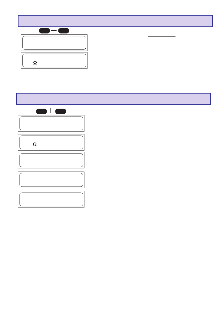
Anzeige der Eingangsspannung und des Innenwiderstandes
DECINC
________________Eingangsspannung
________________
13.62V
Innenwid. Batt.
________________
25m
Die Anzeige des Innenwiderstandes ermöglicht die Kontrolle der Akkuqualität. Der Innenwiderstand wird
beim Laden/Entladen nach wenigen min. gemessen.
Durch drücken der MODE oder START - Taste kehren Sie ins Menü zurück.
Die aktuelle Eingangsspannung und der Innenwiderstand des
Akkus kann jederzeit durch gleichzeitiges Drücken der INCund DEC-Tasten abgerufen werden. Durch drücken der INCoder DEC-Taste wechseln Sie die Anzeige zum Innenwiderstand, den Einzelzellenspannungen oder zur Eingangsspannung.
Die Anzeige der Eingangsspannung ist vor allem sehr nützlich,
wenn Sie eine Autobatterie als Stromquelle verwenden.
Anzeige der Einzelzellenspannungen
DECINC
Eingangsspannung
________________
13.62V
________________
Innenwid.Batt.
________________
25m
________________
]]]]]]]]
________________1.
]]]] 4.153V
]]]]]]]]
________________
]]]]]]]]
2.
________________3.
________________
4. 0.000V
________________5. 0.000V
________________
6. 0.000V
]]
]]]]
] 4.168V
]]]]]]]]
]]
]]]]]]
]]] 4.053V
]]]]]]
Die aktuelle Eingangsspannung und der Innenwiderstand des
Akkus kann jederzeit durch gleichzeitiges Drücken der INCund DEC-Tasten abgerufen werden. Durch drücken der INCoder DEC-Taste wechseln Sie die Anzeige zum Innenwiderstand, den Einzelzellenspannungen oder zur Eingangsspannung.
Die Anzeige der Einzellenspannungen dient der Überprüfung
der einzelnen Zellenspannungen (1-6 Zellen).
19
Page 20
17. Fehler- und Warnmeldungen
Das Ladegerät ist mit einer Vielzahl an Schutz- und Überwachungseinrichtungen zur Kontrolle der
einzelnen Funktionen und der Geräteelektronik ausgestattet. Eine Überschreitung von Grenzwerten
führt in einigen Fällen zur automatischen Reduzierung der Geräteeinstellungen (z.B. Lade- oder
Entladestrom) oder zur Abschaltung des Ladevorganges (z.B. bei leerwerdender Autobatterie).
Die Ursachen dafür werden im Fehlerfall auf der Flüssigkristallanzeige angezeigt. Die meisten Fehlerursachen sind selbsterklärend. Die nachstehende Auflistung soll jedoch bei der Fehlerfindung hilfreich
sein. Die Warnmeldung sowie das akustische Warnsignal sind mit der „ENTER“-Taste abstellbar.
________________
*****FEHLER*****
Autobatt. leer
________________
________________
*****FEHLER*****
Falschpolung
________________
________________
*****FEHLER*****
Unterbrechung
________________
________________
*****FEHLER*****
Ladezeit übersch
________________
________________
*****FEHLER*****
Spann. übersch.
________________
Unterschreitet die Spannung der Autobatterie den im Programm-Menü „Unterspannungsabschaltung“ in den Benutzereinstellungen eingestellten Wert, (11,0 V), so erfolgt diese
Warnmeldung.
Wird an die Ladeanschlüsse des Ladegeräts ein Akku mit
falscher Polarität angeschlossen, so erfolgt diese Warnmeldung.
Stellt das Ladegerät während der Ladung/Entladung eine
Unterbrechung der Verbindung zwischen Akku und Ladegerät
fest, so wird diese Fehlermeldung ausgegeben.
Tritt diese Fehlermeldung während des Betriebs auf, kann dies
auf einen Wackelkontakt hinweisen.
Hinweis: Diese Fehlermeldung erfolgt auch, wenn Sie die
Ladung, z. B. durch Abziehen des Ladekabels unterbrechen.
Ist der interne Ladesicherheitstimer abgelaufen, erfolgt zur
Sicherheit eine Unterbrechung des laufenden Vorgangs.
Der Sicherheitstimer ist bei NiCd/NiMH Akkus fest auf 180min.
eingestellt. Bei Lithium-Akkus auf 180min, bei Bleibakkus ist
dieser deaktiviert. Diese Einstellungen können nicht verändert
werden.
Mögliche Ursachen: Ladestrom zu gering - Akku wird nicht voll,
Ladekabel zu dünn und zu lang - Ladestrom kann nicht weit
genug ansteigen, Kapazität des Akkus zu groß.
Stellt das Ladegerät eine zu hohe Spannung fest z.B. falsche
Einstellung bei der Lithium Zellenzahl oder bei Bleiakkus, so
erscheint diese Fehlermeldung.
Außerdem kann diese Fehlermeldung bei Überladung der
angeschlossenen Zellen erscheinen.
________________
*****FEHLER*****
Spann. untersch.
________________
20
Sollte das Ladegerät eine zu niedrige Spannung feststellen z.
B. falsche Einstellung bei der Lithium Zellenzahl oder bei
Bleibakkus, so erscheint diese Fehlermeldung.
Grund für diese Fehlermeldung ist, dass die Zellen durch die
falsche Einstellung zu tief entladen werden.
Page 21

________________
*****FEHLER*****
Bal.Spg.übersch.
________________
Stellt das Ladegerät eine zu hohe Zellenspannung am Balancereingang fest, so erscheint diese Fehlermeldung.
Die Fehlermeldung erscheint bei folgenden Spannungen:
LiPo > 4,3V, LiIo > 4,2V, LiFe > 3,9V, NiCd/NiMH > 2,0V
Außerdem kann diese Fehlermeldung bei Überladung der
angeschlossenen Zellen erscheinen.
________________
*****FEHLER*****
Bal.Spg.untersch
________________
________________
*****FEHLER*****
BALANCER N. ANG
________________
.
Stellt das Ladegerät eine zu niedrige Zellenspannung am
Balancereingang fest, so erscheint diese Fehlermeldung.
Die Fehlermeldung erscheint bei folgenden Spannungen:
LiPo < 2,75V, LiIo < 2,75V, LiFe < 2,0V, NiCd/NiMH < 0,1V
In diesem Fall empfiehlt sich das Anladen des Akkus für wenige
Minuten (max. 5 min) z. B. im LiFe Programm Modus, das eine
Spannung von 2V pro Zelle zulässt, ohne Balanceranschluss.
Warnung: Es könnten Zellen beschädigt sein und der
Akkupack darf daher nur unter strengster Beobachtung
aufgeladen werden. Sobald die Spannung wieder hoch
genug ist, muss der Akku aus Sicherheitsgründen unbedingt mit angeschlossenem Balancerstecker geladen werden (Explosions- und Brandgefahr)!
Wird das NiCD/NiMH-Entladebalancier-Programm gestartet,
ohne dass der Balancerstecker angeschlossen ist, so erscheint
diese Fehlermeldung.
Wird der Balancerstecker während eines Lade- oder Entladevorgangs abgezogen, so erscheint ebenfalls diese Fehlermeldung.
18. PC-Schnittstelle
Laden Sie sich bei www.graupner.de unter Produktsuche: 6463 die Software des entsprechenden USBSeriell-Treiber CP210x_Drivers.exe für dieses Ladegerät herunter und installieren Sie den Treiber.
Stecken Sie das USB-Kabel in die PC-Schnittstelle des Ladegerätes an. Schließen Sie das USB-Kabel
an eine frei USB-Schnittstelle an den PC an.
Eine PC-Software können Sie unter www.graupner.de, www.gm-racing.de oder www.logview.info
herunterladen.
Mit dieser Software können Sie Kurven anzeigen, vergleichen und vieles mehr.
21
Page 22

19. Reinigung und Wartung
Das Ladegerät arbeitet wartungsfrei und benötigt daher keinerlei Wartungsarbeiten. Bitte schützen Sie
es jedoch in Ihrem eigenen Interesse unbedingt vor Staub, Schmutz und Feuchtigkeit!
Zur Reinigung das Ladegerät von Autobatterie und Akku trennen und nur mit einem trockenen Lappen
(keine Reinigungsmittel verwenden!) leicht abreiben.
20. Hinweise zum Umgang mit Akkus
• Das Laden einzelner NiCd- oder NiMH-Zellen oder Batterien mit 1...4 Zellen stellt die Abschalt-
automatik vor eine schwere Aufgabe, da hier der Spannungs-Peak nicht sehr ausgeprägt ist, kann
eine einwandfreie Funktion nicht garantiert werden. Die Automatik kann nicht oder nicht richtig
ansprechen. Überprüfen Sie deshalb durch mehrfache, überwachte Probeladungen ob bei den von
Ihnen verwendeten Akkus eine einwandfreie Abschaltung erfolgt.
• Warme Batterien sind leistungsfähiger als kalte, wundern Sie sich deshalb nicht wenn Ihre Batterien
im Winter nicht so leistungsfähig sind.
• Überladen sowie Tiefentladung führt zu irreparabler Beschädigung der Zellen und schädigt dauerhaft
die Leistungsfähigkeit des Akkus und vermindert die Kapazität.
• Akkus niemals ungeladen, leer oder teilgeladen für längere Zeit lagern. Vor der Lagerung Akkus
aufladen und von Zeit zu Zeit Ladezustand überprüfen. NiMH-Zellen sollten 1,2V pro Zelle und LiIo/
LiPo-Zellen sollten 3V pro Zelle niemals unterschreiten, um eine optimale Lebensdauer zu erreichen.
• Beim Kauf von Akkus auf gute Qualität achten, neue Akkus zunächst nur mit kleinen Strömen aufladen
und erst allmählich an höhere Ströme herantasten.
• Akkus erst kurz vor der Verwendung aufladen, die Akkus sind dann am leistungsfähigsten.
• An den Akkus nicht löten - Die beim Löten auftretenden Temperaturen beschädigen meist die
Dichtungen und Sicherheitsventile der Zellen, der Akku verliert daraufhin Elektrolyt oder trocknet aus
und büßt seine Leistungsfähigkeit ein.
• Überladung schädigt die Kapazität des Akkus. Deshalb keine heißen oder bereits geladenen Akkus
erneut aufladen.
• Hochstromladungen und -entladungen verkürzen die Lebenserwartung des Akkus. Überschreiten Sie
daher nicht die vom Hersteller vorgegebenen Angaben.
• Bleibatterien sind nicht hochstromladefähig. Überschreiten Sie daher niemals die vom Akkuhersteller
angegebenen Ladeströme.
• Akkus vor Vibration schützen sowie keiner mechanischen Belastungen aussetzen.
• Beim Laden und während des Betriebs der Akkus kann Knallgas (Wasserstoff) entstehen, achten Sie
deshalb auf ausreichende Belüftung.
• Batterien nicht mit Wasser in Berührung bringen, Explosionsgefahr.
• Batteriekontakte niemals kurzschließen, Explosionsgefahr.
• Akkus können durch einen Defekt Explodieren oder brennen. Wir empfehlen daher bei allen Li-
Akkus sowie NiCd und NiMH-Akkus die Akkus in einem LiPo-Sicherheitskoffer Best.-Nr. 8370
oder 8371 zu laden.
• Batterien nicht öffnen, Verätzungsgefahr.
• NiCd- oder NiMH-Akkupacks lassen sich am besten formieren indem zuerst alle Zellen einzeln und
separat entladen werden und anschließend den Akkupack aufladen. Das Entladen erfolgt mit dem
Ladegerät (Zelle für Zelle).
• Wundern Sie sich auch nicht, wenn Ihre Akkupacks im Winter nicht so ladewillig sind wie im Sommer.
Eine kalte Zelle ist nicht so stromaufnahmefähig wie eine warme.
• Hinweise zur Batterieverordnung: Verbrauchte Batterien sind Sondermüll und dürfen nicht über die
Mülltonne entsorgt werden. Im Fachhandel, wo Sie die Batterien erworben haben, stehen BatterieRecycling-Behälter für die Entsorgung bereit. Der Handel ist zur Rücknahme verpflichtet.
22
Page 23
21. Technische Daten
Akku:
Ladeströme / Leistung 100mA bis 5,0A / max. 50W mit 12...15VDC-Anschluss
Entladeströme / Leistung 100 mA - 1 A / max. 5 W
Ni-Cd & Ni-MH-Akkus:
Zellenzahl 1 - 14 Zellen
Kapazität ab 0,1 Ah bis 9,9 Ah
Lithium-Akkus:
Zellenzahl 1-6 Zellen
Zellenspannungen 3,3V (LiFe), 3,6 V (LiIo) bzw. 3,7 V (LiPo/LiMn)
Kapazität ab 0,1 Ah-9,9 Ah
PB-Akkus:
Zellenzahl 1, 2, 3, 6
Akkuspannungen 2, 4, 6, 12 V
Kapazität ab 1 Ah
Sonstiges:
Betriebsspannungsbereich DC-Eingang: 11,0 bis 15 V
Betriebsspannungsbereich AC-Eingang: 100~240V
Erforderliche Autobatterie 12 V, min. 30 Ah
Erforderliches Netzgerät für 12V DC-Anschluss: 12-14V, min. 5A stabilisiert
Leerlaufstromaufnahme ca. 0,1A
Unterspan.-Abschaltung ca. 11,0 V
Balanceranschluss: 1...6 NiMH/NiCd/LiPo/LiIo/LiFe Zellen
Balancierstrom max. ca: NiMH/NiCd: 0,1A, LiPo/LiIo/LiFe: 0,3A
Gewicht ca. 210 g
Abmessungen ca. (BxTxH) 123 x 85 x 28 mm
am Eingang
1)
Alle Daten bezogen auf eine Autobatteriespannung von 12.7 V.
Die angegeben Werte sind Richtwerte, die abhängig vom verwendeten Akkuzustand, Temperatur usw. abweichen können.
1)
Der einwandfreie Betrieb des Ladegeräts an einem Netzteil ist von vielen Faktoren wie z.B. Brummspannung, Stabilität, Lastfestigkeit
usw. abhängig. Bitte verwenden Sie nur die von uns empfohlenen Geräte.
Hinweise zum Umweltschutz
Das Symbol auf dem Produkt, der Gebrauchsanleitung oder der Verpackung weist darauf hin,
dass dieses Produkt bzw. elektronische Teile davon am Ende seiner Lebensdauer nicht über den
normalen Haushaltsabfall entsorgt werden dürfen. Es muss an einem Sammelpunkt für das Recycling von
elektrischen und elektronischen Geräten abgegeben werden.
Die Werkstoffe sind gemäß ihrer Kennzeichnung wiederverwertbar. Mit der Wiederverwendung, der stofflichen
Verwertung oder anderen Formen der Verwertung von Altgeräten leisten Sie einen wichtigen Beitrag zum
Umweltschutz.
Batterien und Akkus müssen aus dem Gerät entfernt werden und bei einer entsprechenden Sammelstelle
getrennt entsorgt werden.
Bei RC-Modellen müssen Elektronikteile, wie z.B. Servos, Empfänger oder Fahrtenregler aus dem Produkt
ausgebaut und getrennt bei einer entsprechenden Sammelstelle als Elektro-Schrott entsorgt werden.
Bitte erkundigen Sie sich bei der Gemeindeverwaltung die zuständige Entsorgungsstelle.
23
Page 24

Chapter Page
Contents
1. Introduction 24
2. Warnings and safety notes, please read and observe! 25
3. General notes on using the charger 26
4. Recommended charge leads, polarity 27
5. Controls, using the charger, starting the charge process 27
6. Charge and discharge programs 28
7. Program flowchart 28
8. Selecting the charge program group 29
9. Using the charger for the first time 29
10. Starting the charge / discharge process 30
11. Nickel-Cadmium (Ni-Cd) charge programs 31
12. Nickel-Metal-Hydride (Ni-MH) charge programs 33
13. Lithium-Ion / Lithium-Polymer / Li-Mn / LiFePO4- charge programs 36
14. Lead-acid (Pb) charge programs 38
15. Screen displays, cycle data display 40
16. Monitor displays 40
17. Error messages, warnings 42
18. PC interface 43
19. Cleaning and maintenance 44
20. Notes on handling rechargeable batteries 44
21. Specification, Environnemental Protection Notes 45
Guarantee certificate Back cover
1. Introduction
Please study these instructions, reading them completely and attentively, before using
the unit for the first time. This will guarantee that you will be able to exploit all the
facilities of your new battery charger. The warnings and safety notes are particularly
important. Please store these instructions in a safe place, and be sure to pass them on
to the new owner if you ever dispose of the charger.
In the charger you have acquired a mature product with an excellent performance. It
incorporates the latest semi-conductor technology, controlled by a high-performance RISC
micro-processor, to provide superior charging characteristics combined with simple operation
and optimum reliability. These features can normally be expected only from much more expensive units. The charger represents a reliable method of charging sintered Nickel-Cadmium (NC,
Ni-Cd) packs, Nickel-Metal-Hydride (Ni-MH) batteries, Lithium-Polymer (Li-Po), LithiumManganese (Li-Mn), Lithium-Ion (Li-Io) and LiFePO4 (LiFe) batteries, and also lead-gel and leadacid (Plumbum: Pb) batteries These sealed, gas-tight batteries have proved excellent for our
purposes in RC models. They are mechanically robust, can be used in any attitude and are
generally highly reliable. They require no special measures for storage apart from protecting the
cells from becoming deep-discharged. The charger can also be used to discharge your batteries
and balance the cells in a pack.
Note
It is important always to observe the charging instructions supplied by the battery manufacturer,
and to keep to the recommended charge currents and times Do not fast-charge batteries unless
the manufacturer states expressly that they are suitable for the high currents which flow during
these processes. When charging new batteries you may also encounter problems with
premature charge termination. Whenever you wish to use a new battery it therefore makes
sense to carry out a series of monitored test charges, so that you can check that the automatic
charge termination circuit works correctly and reliably with your packs, and charges them to full
capacity.
24
Page 25

2. Warnings and safety notes
z This product isn‘t designed for use by children under the age of 14, it isn‘t a toy!
z Protect the charger from dust, damp, rain, heat (e.g. direct sunshine) and vibration. It should only be
operated in dry indoor conditions.
z The case slots serve to cool the charger, and must not be covered or enclosed; set up the charger
with space round it, so that cooling air can circulate unhindered.
z The charger is designed to be powered by a 12 V DC car battery or power supply. It is not permissible
to modify the charger in any way.
z The charger and the battery to be charged should be set up on a heat-resistant, non-inflammable
and non-conductive surface before use. Never place the charger directly on a car seat, carpet or
similar. Keep all inflammable and volatile materials well away from the charging area. Provide good
ventilation. Defective batteries can explode or burn!
z Connect the charger 12DC input directly to the car battery using the original cables and connectors
supplied.
Do not recharge the car battery at any time when the charger is connected to it.
z The charge output sockets and connecting leads must not be modified, and must not be inter-
connected in any way. There is a danger of short-circuit between the charge outputs and the vehicle’s
bodywork when the charger is connected to the car battery. The charge leads and connecting leads
must not be coiled up when the charger is in use. Avoid short-circuiting the charge output or the
model battery with the car bodywork. For this reason the charger must never be placed directly on the
vehicle’s bodywork.
z Never leave the charger running or connected to the car battery unsupervised.
z Only one battery may be connected to the unit for charging at any one time.
z The following types of battery must not be connected to the charger:
- Ni-Cd / Ni-MH batteries consisting of more than 14 cells, Lithium-Ion / Li-Mn / Lithium-Polymer /
- Batteries which require a different charge method from Ni-Cd, Ni-MH, Lithium or lead-acid types.
- Faulty or damaged cells or batteries.
- Batteries consisting of parallel-wired cells, or cells of different types.
- Batteries consisting of old and new cells, or cells of different makes.
- Non-rechargeable batteries (dry cells). Caution: explosion hazard!
- Batteries which are not expressly stated by the manufacturer to be suitable for the currents which
- Packs which are already fully charged or hot, or only partially discharged.
- Batteries or cells fitted with an integral charge circuit or charge termination circuit.
- Batteries installed in a device, or which are electrically connected to other components.
z To avoid short-circuits between the banana plugs fitted to the charge leads, please always connect
the charge leads to the charger first, and only then to the battery to be charged. Reverse the sequence
when disconnecting.
z As a basic rule always check that the charge quantity is approximately the same as you expected after
the charger has indicated that the pack is fully charged. This is a simple method of detecting a problem
reliably and in good time, should the charge process be terminated prematurely for any reason. The
likelihood of premature termination varies according to many factors, but is at its highest with deepdischarged packs, low cell counts and particular cell types which are known to cause problems.
z We recommend that you carry out a series of test charges to satisfy yourself that the automatic
termination circuit is working perfectly. This applies in particular when you are charging packs consisting
of a small number of cells. If the cells feature has a poorly defined voltage peak, the charger may fail
to detect the fully charged state.
z Before charging please check: have you selected the appropriate charge program for the battery?
Have you set the correct charge or discharge current? Have you set the important cut-off voltage
when charging Ni-Cd and Ni-MH packs? Are all connections firm, or is there an intermittent contact at
any point in the circuit? Please bear in mind that it can be dangerous to fast-charge batteries. For
example, if there is a brief interruption due to an intermittent contact, the result is inevitably a
malfunction such as a restart of the charge process, which would result in the pack being massively
overcharged.
The car’s engine must be stopped all the time the charger is connected to the car’s battery.
LiFePO4 (LiFe) batteries of more than 6 cells, or lead-acid batteries with a nominal voltage of more
than 12V.
this unit delivers during the charge process.
25
Page 26

3. General notes on using the charger
Charging batteries
When a battery is charged, a particular quantity of electrical energy is fed into it. The charge
quantity is calculated by multiplying charge current by charge time. The maximum permissible
charge current varies according to the battery type, and can be found in the information provided
by the battery manufacturer.
It is only permissible to charge batteries at rates higher than the standard (slow) current if they are
expressly stated to be rapid-charge capable. The STANDARD CHARGE CURRENT is 1/10 (one
tenth) of the cells’ nominal capacity (e.g. for a 1.7 Ah pack the standard charge current is 170 mA).
• Connect the battery to be charged to the charger output sockets using a suitable charge lead (red
= positive terminal, black = negative terminal).
• Be sure to read the information provided by the battery manufacturer regarding charging methods,
and observe the recommended charge currents and charge times. Do not attempt to fast-charge
batteries unless they are expressly stated to be suitable for the high currents which this charger
delivers.
• Please bear in mind that new batteries do not reach their full capacity until they have undergone
several charge / discharge cycles. You should also be aware that the charger may terminate the
charge process prematurely when connected to new packs, and batteries which have been
deep-discharged.
• A Ni-Cd pack will normally be warm at the end of a rapid-charge process, but if you notice that one
cell of the pack is much hotter than the others, this may well indicate a fault in that cell. Such packs
could fail completely without warning, and should not be used again. Dispose of the battery safely,
preferably taking it to a toxic waste disposal centre.
• Ensure that all connectors and terminal clamps make good, sound contact. For example, if there
is a brief interruption due to an intermittent contact, the result is inevitably a malfunction such as
a restart of the charge process, which would result in the pack being massively overcharged.
• A common cause of malfunctions is the use of unsuitable charge leads. Since the charger is
incapable of detecting the difference between a pack’s internal resistance, cable resistance and
connector transfer resistance, the first requirement if the charger is to work perfectly is that the
charge lead should be of adequate conductor cross-section and should be not be more than
30 cm long Good-quality connectors (gold-contact types) must be fitted to both ends.
• Charging transmitter batteries
A battery installed in a radio control transmitter can usually be recharged via the integral charge
socket which is fitted to the transmitter itself. Transmitter charge sockets generally include a
diode which prevents reverse current flow. This prevents damage to the transmitter electronics
should the charger be connected with reverse polarity, or if a short-circuit occurs between the
bare ends of the charge lead connectors. However, a transmitter battery protected in this way
can only be charged by the charger if the diode is by-passed. Please read your transmitter
operating instructions for information on how to do this. The stated maximum charge current for
the transmitter battery must never be exceeded. To avoid possible damage to the internal
transmitter components due to overheating and heat build-up, we recommend that the battery
should be removed from the transmitter’s battery compartment prior to charging. The transmitter
must be set to „OFF“ and left in that state for the whole period of the charge process.
Never switch a radio control transmitter on when it is still connected to the battery charger. The
slightest interruption in the charge process may allow the charge voltage to rise to the point
where it immediately ruins the transmitter.
Never attempt to carry out any battery discharge or battery maintenance programs via the
transmitter’s integral charge socket. The charge socket is not suitable for this purpose.
When you set a particular current for charging, the charger only supplies that current if the
value does not exceed the unit’s technical capacity. If you set a charge current which the
ULTRAMAT 16 S cannot deliver because it falls outside its technical limits, the unit
automatically reduces the current to the maximum possible value. In this case the
screen displays the charge current which is actually flowing, alternating with
the warning message „MAX“.
26
Page 27
Liability exclusion
As manufacturers, we at GRAUPNER are not in a position to ensure that you observe the
correct methods of operation when installing, using and maintaining this charger. For this reason
we are obliged to deny all liability for loss, damage or costs which are incurred due to the
incompetent or incorrect use and operation of our products, or which are connected with such
operation in any way.
4. Recommended charge leads /polarity
The requirements made on rechargeable batteries vary greatly according to their particular
application, and this in turn calls for different types of battery connector. Please note that
connectors, connector names and polarities may vary from one manufacturer to another. For
this reason we recommend that you always use genuine matching connectors of identical
construction. The following charge leads are suitable for battery charging with this unit:
Japan
Order No. 3371
Be sure to use genuine charge leads fitted with cable of adequate conductor cross-section.
G2 (AMP/G2,5)
Order No. 3011
BEC
Order No. 3037JROrder No. 3021
JR-Sender
Order No. 3022
5. Charger controls / Using the charger / Starting the process
Connectors for
12...15V DC
power supply
or car battery
-
Car battery
terminal clips
+
-
All the charger’s functions are controlled by means of just four buttons.
The - / DEC and + / INC buttons are used to change the current and voltage values. The function
of the other two buttons varies according to the presence or otherwise of a battery at the charge
sockets:
Operating button Function
No battery PROGRAMM/MODE Select charge programs and sub-groups
connected: PROGRAMM/MODE 2s. Select the (charge) program group
ENTER/START Select next position of a discharge/cycle adjustment
Battery PROGRAMM/MODE Ends the charge process, stops the buzzer,
connected: Select next position of a discharge/cycle adjustment
ENTER/START 2 sec. Starts the charge process
Screen
Operating buttons
BALANCER
CONNECTOR for
Graupner LiPobattery
power output
„BATTERY “
27
Page 28
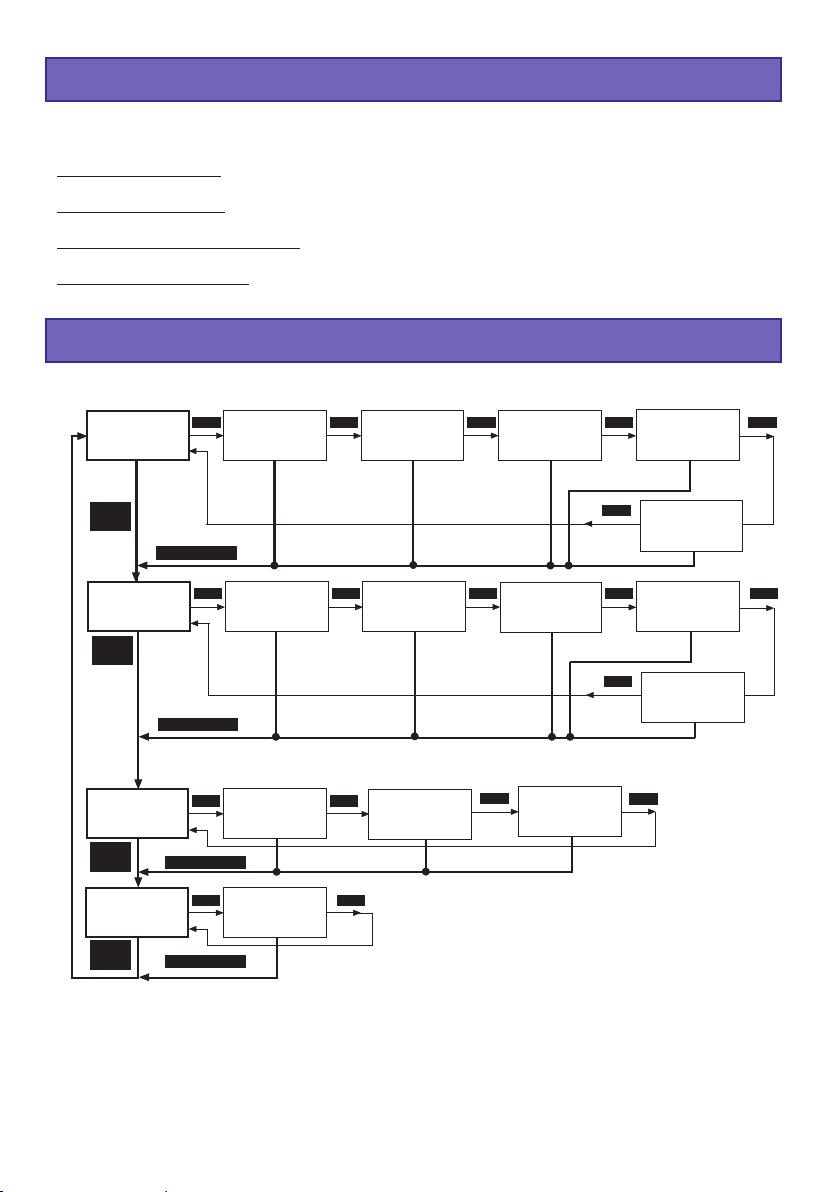
6. Charge and discharge programs
The various facilities of the charger are divided up into four program groups which you can select by
holding the MODE button pressed in for two seconds. The sequence is shown in the flow chart
below.
Ni-Cd battery programs: charging, conditioning, discharging to determine capacity or residual
capacity, or to select cells.
Ni-MH battery programs: charging, conditioning, discharging to determine capacity or residual
capacity, or to select cells.
LiPo / LiIo / LiFe battery programs: charging, discharging to determine capacity or residual capacity,
or to select cells.
Lead-acid battery programs: charging, discharging to determine capacity or residual capacity, trickle
charge for stand-by operation.
7. Program flowchart
NiCd
AUTOMATIC-
program
MODE
(2 sec.)
NiMH
AUTOMATIC-
program
MODE
(2 sec.)
Lithium
MANUAL-
program
MODE
(2 sec.)
Pb
MANUAL-
program
MODE
(2 sec.)
NiCd
discharge balancing
program
NiCd
∆ ∆
∆
delta-peak
∆ ∆
trigger voltage
NiMH
discharge balancing
program
NiMH
∆ ∆
∆
delta-peak
∆ ∆
trigger voltage
MODE
MODE
NiCd
cycle
program
NiMH
cycle
program
Lithium
type
select
MODE
MODE
MODE MODE MODE MODE MODE
MODE (2 sec.)
MODE MODE MODE MODE MODE
MODE (2 sec.)
MODE MODE
MODE (2 sec.)
MODE MODE
MODE (2 sec.)
NiCd
MANUAL-
program
NiMH
MANUAL-
program
Lithium
discharge
program
Pb
discharge
program
NiCd
discharge
program
NiMH
discharge
program
Lithium
storage
program
28
Page 29

8. Selecting the charge program group
NiCd
AUTOMATIC
program
MODE (2 sec.)
NiMH
AUTOMATIC
program
MODE (2 sec.)
Lithium
MANUAL
program
MODE (2 sec.)
Pb
MANUAL
program
MODE (2 sec.)
In the interests of clarity, the charge and set-up facilities of the
MODE
charger are divided into four logical program groups.
A separate program group is provided for each of the different
battery types: Nickel-Cadmium, Nickel-Metal-Hydride, Lithium-
Ion / Lithium-Polymer / LiFePO4 (LiFe) and Pb (lead-acid)
MODE
batteries.
Switching programs:
MODE
yy
y Changing from one program group to another is carried out using
yy
the MODE button, which must be held pressed in for about two
seconds. A brief press on the MODE button makes changes within
MODE
the program group.
9. Using the charger for the first time
When the INC and DEC buttons are pressed simultaneously and the charger is initially connected
to a 12 V DC car battery or power supply, the unit goes to the language select menu, otherwise it
runs through the information routine which provides you with a brief summary of the essential user
settings. The charger’s screen displays the following information.
DECINC
________________
LANGUAGE SELECT
ENGLISH
________________
ENTER
Press and hold the INC and DEC buttons simultaneously,
then switch on the charger to get the language selection
display. Select your language using the INC or DEC button
and confirm with pressing the ENTER button.
________________
Graupner V1.00
U12 PLUS POCKE T
________________
3 sec.
________________
Safety timer
on
________________
3 sec.
________________ bu z z e r
on
________________
The ULTRAMAT 12 PLUS’s name appears on the screen.
After 3 sec. the adjustment of the safety timer (on or off) is
displayed. For about 3 sec. the safety timer can be adjusted
by pushing the INC or DEC button. (10...300min, off)
The safety timer is always switched off for discharging and for
Pb manual charge.
After another 3 sec. the adustment of the buzzer (off, on,
3...10s) can be changed by pushing the INC or DEC
button.
After another 3 sec. the charger is now ready for use, see
10..
29
Page 30

10. Starting the charge / discharge process
3 sec.
________________LiPo manual
C:2.5A 2000mAh
________________
START
________________**INFORMATION***
BALANCER CON.
________________
START
________________BATTERY CHECK
WAIT PLEASE...
________________
2
sec.
2
sec.
For charging / discharging, or conditioning a pack, select
the desired program as described below, and then set
suitable values.
If the battery does have a balancer connector, connect the
balancer connector to the balancer input (BALANCER
CONNECTOR) of the charger.
Make sure for the right polarity.
From right handed to left side:
Pin 1 (GND): Ground = battery -,
Pin 2 (1): + cell 1, Pin 3 (2): + cell 2, Pin 4 (3): + cell 3,
Pin 5 (4): + cell 4, Pin 6 (5): + cell 5, Pin 7 (6): + cell 6
Connect the two pole power charging cable of the battery to
the charger output - BATTERY + with the right polarity.
Hold the START button pressed in for about two seconds,
and the charger display, if the balancer connector is
connected or not. With connected balancer connector the
single cell voltages can be displayed, see 16..
________________**INFORMATION***
BALANCER NOT CON
________________
2
sec.
________________BATTERY CHECK
WAIT PLEASE...
________________
2
sec.
________________CHG 23:40 00863
LP+2.50A 14.017V
________________
30
If a Li-battery is connected and the balan2
sec.
________________
***LiPo cells***
3 cells (13.73V)
________________
+
INC
DEC
START
Press the START button again,
and the charger will assess the
battery.
You can interrupt the charge process at any time with another
short press on the START button.
Note: if you interrupt the charge process by pressing
the START button, all display parameters are
irretrievably erased.
cer connector is not connected, the char-
ger will display the cell count of the Lithium
pack, which must be corrected manually,
if it is wrong..
! Caution ! Please
take great care to set
-
the correct cell
count. and the right
battery type. If you
make a mistake, the
battery could
explode and burst
into flames !
Page 31

11. Ni-Cd programs
NiCd
AUTOMATIC-
program
MODE MODE MODE MODE MODE
NiCd
MANUAL-
program
NiCd
discharge
program
NiCd
cycle
program
MODE
NiCd
discharge balancing
program
NiCd
∆ ∆
∆
delta-peak
∆ ∆
trigger voltage
A set of convenient charge programs for recharging Nickel-Cadmium batteries, as commonly
used for modelling purposes. When the charge / discharge program is finished, the screen
displays the name of the charge program alternating with the message „END“, together with the
charge time, the last (dis-) charge current, the charged-in (discharged) capacity and the battery
voltage, and continues to do so until you disconnect the battery. This information can often give
you a useful indication about the Ni-Cd pack’s charge characteristics and capacity, or warn you
if the charger has incorrectly assessed the pack as being „full“.
Ni-Cd automatic program
________________NiCd automatic
C:2.5A limited
________________
+
-
DECINC
In this program the charger detects the type of Ni-Cd
battery connected to it, and adjusts the charge current
accordingly to avoid overcharging the pack.
The maximum charge current can be set before you
connect the battery to be charged. This is done using the
INC / DEC buttons; the range available is 0.1 A to 5,0 A, or
no restriction. The charge process is terminated automatically in accordance with the values already set for
„Ni-Cd Delta Peak cut-off voltage“.
Ni-Cd manual program
________________NiCd manual
C:2.5A
________________
+
INC
-
DEC
Ni-Cd discharge program
________________NiCd discharge
1.00A 4.8V
________________
+
INC
-
DEC
ENTER
+
INC
DEC
Select this program when you simply wish to recharge a
battery using the set charge current.
You can adjust the charge current using the INC / DEC
buttons, but only before you connect the pack for
charging. The range available is 0.1 A to 5,0 A.
The charge process is terminated automatically in
accordance with the values already set for „Ni-Cd Delta
Peak cut-off voltage“.
The typical purpose of this program is to determine the
residual capacity of a transmitter, receiver or drive
battery, or to discharge the pack to a defined level.
In this program the charger discharges the pack using the
-
set discharge current (0.1 ... 1.0 A, left of screen) until its
voltage falls to the set final discharge voltage (0.1 ... 16.8
V, right of screen).The set final discharge voltage should
be a value of around 0.9 ... 1,1 V per cell, in order to avoid
the pack becoming deep-discharged. Deep-discharging a
pack runs the risk of reversing individual cells, i.e. they
exhibit reversed polarity.
31
Page 32

NiCd conditioning program
ENTER
INC
INC
or
DEC
DEC
________________NiCd cycle C>D 1
C:2.5A
________________
+
INC
-
DEC
ENTER
D
:1.00A
+
INC
DEC
NiCd discharge balancing program
NiCd balance cut
________________
off volt = 1.20V
________________
+
INC
DEC
START
________________**INFORMATION***
BALANCER CON.
________________
DCH
BLC 28:30 01425
DCH
________________
________________
NC-3.00A 06.717V
2
sec.
2
sec.
This program is designed to optimise the capacity of a
battery, and balance the state of its component cells.At
top right you can set use the INC or DEC buttons to
determine whether the conditioning program is to start
with a charge or discharge cycle. After this you set the
number of cycles from 1 to 5 (e.g., if you set three cycles,
the pack will be charged and discharged three times). The
program discharges the battery using the set discharge
current stated on the right of the screen (0.1 ... 1.0 A),
and then recharges it using the charge current (0.1 ...
10.0 A) shown on the left of the screen. The charge
-
process is terminated automatically in accordance with
the values already set for „Ni-Cd Delta Peak cut-off
voltage“. The discharge cut-off voltage is set in the Ni-Cd
discharge program. The method of reading out the values
for the actual cycle is described in the section „Screen
displays“.
The discharge balancing program does discharge and balance
up to 6 cells of a battery pack.
The final discharge voltage for the balancer can be set
within the range 1.20 … 1.30 V using the INC or DEC
button.
The individual cells in a battery should be balanced before
-
the pack is charged, to avoid the possibility of individual
cells being overcharged during the charge process. A
battery should always be balanced before being charged
if it has been stored for a considerable period;
connect the balancer plug to the charger to carry this out.
It is also essential that the voltage of each cell in the pack
should be higher than the set balancer final discharge
voltage.
If you wish to obtain maximum battery capacity, the
individual cells should be discharged to 1.20 V a few hours
- but no longer than two hours - before the next charge
process. If the voltage falls below 1.20 V, the battery cells
lose capacity, so the pack must be charged to around
60% capacity before being stored for a protracted period.
The program discharges the battery pack at a rate of 50
mA … 5.00 A. Cells with a higher cell voltage are
discharged at an additional current of around 100 mA
(balancing current). The charger terminates the discharge
balance process once all the cells have reached the
balancer final discharge voltage (+0.01 V).
32
Page 33

NiCd-Delta-Peak (-
∆∆
∆ Peak)
∆∆
trigger voltage
________________NiCd delta-peak-
volt =10mV/cell
________________
+
-
DECINC
The automatic charge termination
circuit (battery full detection) works on
the proven Delta Peak principle (also
known as the Delta-V process), which
is already in use in millions of chargers.
cell voltage
charging time
This process analyses the voltage peak of the charge curve, which indicates with great
accuracy when the maximum charge capacity is reached.When the charge process is started
the battery voltage initially rises continuously, but as the pack approaches full capacity it begins
to heat up. This in turn causes the battery voltage to fall slightly (Delta-V). The charger detects
and assesses the voltage decline.It is possible to adjust the sensitivity, or trigger voltage (in mV
per cell!) of the automatic cut-off circuit for Ni-Cd batteries. A practical range of values has
proved to be 10 … 30 mV / cell. Higher voltages often lead to overcharging of the battery,
whereas a lower voltage tends to result in premature termination of the charge process. We
recommend that you check the information supplied by your battery manufacturer, then carry
out a series of test charges to establish the optimum value for your battery. Start with 10mV/cell
to avaid overcharging the battery.
12. NIMH-programs
NiMH
AUTOMATIC-
program
MODE
(2 sek.)
MODE MODE MODE MODE MODE
NiMH
MANUAL-
program
NiMH
discharge
program
A set of convenient charge programs for recharging Nickel-Metal-Hydride batteries, as
commonly used for modelling purposes. When the charge / discharge program is finished, the
screen displays the name of the charge program alternating with the message „END“, together
with the charge time, the last (dis-) charge current, the charged-in (discharged) capacity and
the battery voltage, and continues to do so until you disconnect the battery. This information can
often give you a useful indication about the Ni-MH pack’s charge characteristics and capacity, or
warn you if the charger has incorrectly assessed the pack as being „full“.
NiMH
cycle
program
discharge balancing
MODE
NiMH
program
NiMH
∆ ∆
∆
delta-peak
∆ ∆
trigger voltage
Ni-MH automatic program
________________ NiMH automatic
C:2.5A limited
________________
+
INC
-
DEC
In this program the charger detects the type of Ni-MH
battery connected to it, and adjusts the charge current
accordingly to avoid overcharging the pack.
The maximum charge current can be set before you
connect the battery to be charged.
Never use a maximum charge current higher as the value
described in the battery instruction, never higher as 2C!
Never charge transmitter batteries with more as 2A!
f. e. a 4.2Ah battery should be limited to max. 4.2A.
This is done using the INC / DEC buttons; the range
available is 0.1 A to 5.0 A, or no restriction.
The charge process is terminated auto-matically in
accordance with the values already set for „Ni-MH Delta
Peak cut-off voltage“.
33
Page 34

Ni-MH manual program
________________NiMH manual
C:2.5A
________________
+
-
DECINC
Ni-MH discharge program
________________NiMH discharge
1.00A 4.8V
________________
+
-
DECINC
ENTER
+
INC
Select this program when you simply wish to recharge a
battery using the set charge current. You can adjust the
charge current using the INC / DEC buttons, but only
before you connect the pack for charging. The range
available is 0.1 A to 5.0 A.
Never use a maximum charge current higher as the value
described in the battery instruction, never higher as 2C!
Never charge transmitter batteries with more as 2A!
f. e. a 4.2Ah battery should be limited to max. 4.2A.
The charge process is terminated automatically in
accordance with the values already set for „Ni-MH Delta
Peak cut-off voltage“.
The typical purpose of this program is to determine the
residual capacity of a transmitter, receiver or drive battery,
or to discharge the pack to a defined level.
In this program the charger discharges the pack using the
-
set discharge current (0.1 ... 1.0 A, left of screen) until its
DEC
voltage falls to the set final discharge voltage (0.1 ... 16.8 V,
right of screen).
The set final discharge voltage should be a value of around
1.0 ... 1.2 V per cell, in order to avoid the pack becoming
deep-discharged. Deep-discharging a pack runs the risk of
reversing individual cells, i.e. they exhibit reversed polarity.
ENTER
INC
DEC
________________
NiMH cycle C>D 1
________________
C:2.5A
+
DEC
INC
-
ENTER
D
:1.00A
+
INC
34
Ni-MH conditioning program
This program is designed to optimise the capacity of a
battery, and balance the state of its cells.
At top right you can use the INC or DEC button to determine
INC
or
whether the conditioning program is to start with a charge or
discharge cycle. After this you set the number of cycles
DEC
from 1 to 5 (e.g., if you set three cycles, the pack will be
charged and discharged three times). The program discharges the battery using the set discharge current stated
on the right of the screen (0.1 ... 1.0 A), and then recharges
it using the charge current (0.1 ... 5.0 A) shown on the left of
the screen. The charge process is terminated automatically
-
in accordance with the values already set for „Ni-MH Delta
DEC
Peak cut-off voltage“. The discharge cut-off voltage is set in
the Ni-MH discharge program. The method of reading out
the values for the actual cycle is described in the section
„Screen displays“.
Page 35

Ni-MH discharge balancing program
NiMH balance cut
________________
off volt = 1.20V
________________
+
INC
DEC
START
________________**INFORMATION***
BALANCER CON.
________________
DCH
BLC 28:30 01425
DCH
________________
________________
NM-3.00A 06.717V
2
sec.
2
sec.
The discharge balancing program does discharge and balance
up to 6 cells of a battery pack.
The final discharge voltage for the balancer can be set
within the range 1.20 … 1.30 V using the INC or DEC
button.
The individual cells in a battery should be balanced before
-
the pack is charged, to avoid the possibility of individual
cells being overcharged during the charge process. A
battery should always be balanced before being charged
if it has been stored for a considerable period;
connect the balancer plug to the charger to carry this out.
It is also essential that the voltage of each cell in the pack
should be higher than the set balancer final discharge
voltage.
If you wish to obtain maximum battery capacity, the
individual cells should be discharged to 1.20 V a few hours
- but no longer than two hours - before the next charge
process. If the voltage falls below 1.20 V, the battery cells
lose capacity, so the pack must be charged to around
60% capacity before being stored for a protracted period.
The program discharges the battery pack at a rate of 50
mA … 1.0 A. Cells with a higher cell voltage are
discharged at an additional current of around 100 mA
(balancing current). The charger terminates the discharge
balance process once all the cells have reached the
balancer final discharge voltage (+0.01 V).
Ni-MH-Delta-Peak (-
________________NiMH delta-peak-
volt = 5mV/cell
________________
+
-
DECINC
∆∆
∆ Peak)
∆∆
It is possible to adjust the trigger voltage (in mV per cell!) of
the automatic termination circuit for Ni-MH batteries.
However, Ni-MH batteries have a less pronounced voltage
drop than Ni-Cd cells, and a practical range has proved to
be 5 ... 25 mV / cell. If the trigger voltage is set higher, there
is a danger of overcharging the battery; if set lower, there is
a danger of premature termination.
We recommend that you carry out a series of test charges
to establish the ideal trigger value for your batteries. Start
with 5mV / cell.
trigger voltage
35
Page 36
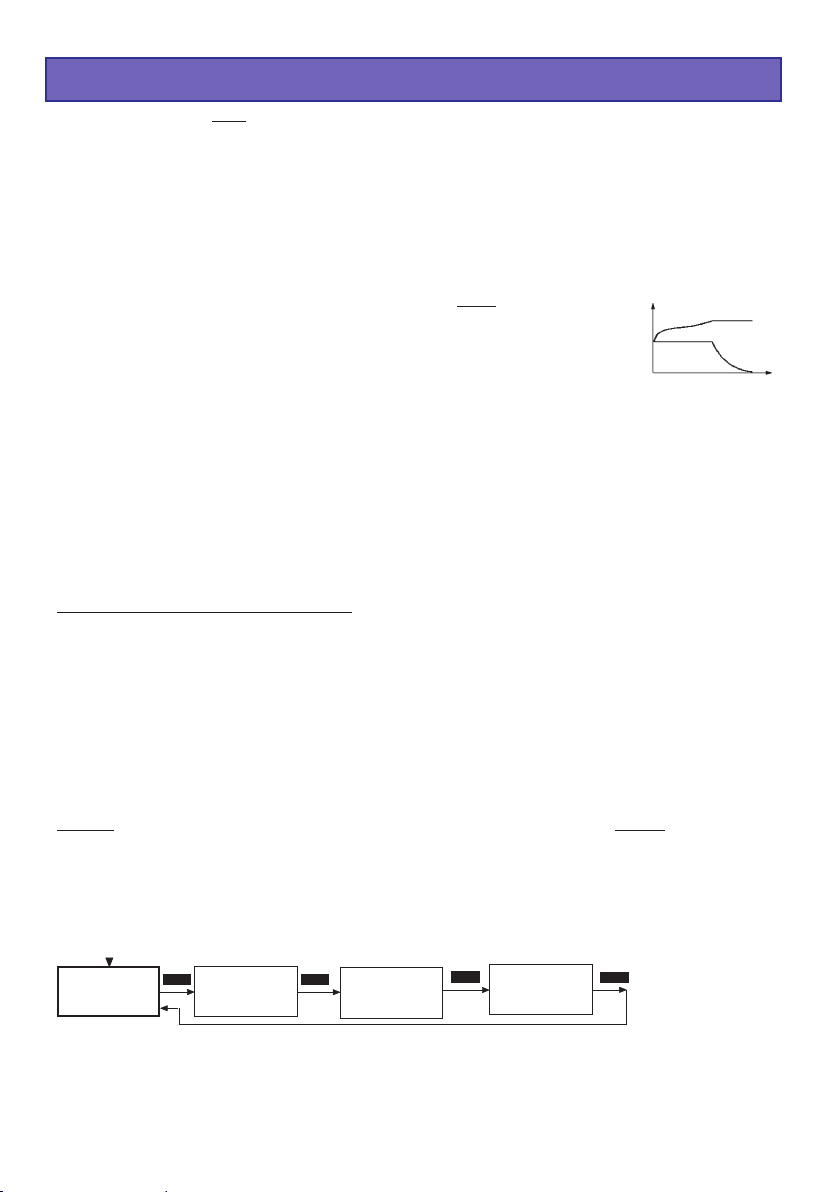
13. Lithium programs
These programs are only suitable for charging and discharging LiFePO4 batteries with a voltage
of 3.3 V / Cell, Lithium-Ion batteries with a voltage of 3.6 V / cell, and Lithium-Polymer and
Lithium-Manganese batteries with a voltage of 3.7 V / cell. The outstanding feature of Lithium
batteries is their much higher capacity compared to other battery types. However, this important
advantage is offset by the need to adopt different handling strategies: they must be charged and
discharged using specific methods, otherwise they will be damaged, and can be dangerous. The
directions in these instructions must be observed at all times when handling these batteries.
Specific information and safety notes will also be found in the battery manufacturer’s technical
information.
The fundamental rule is that Lithium-based batteries may ONLY be charged using
special chargers, and the charge program must be set up correctly in terms of final
charge voltage and capacity for the battery type in use. The charge process is
fundamentally different to that required for Ni-Cd or Ni-MH batteries, and is termed
a constant current / constant voltage method. The charge current required varies
according to the battery capacity, and is set automatically by the charger. Lithium
batteries are usually charged at the 1C rate (1C charge rate = half capacity as charge current. Example:
battery capacity 1500 mAh: 1C charge current = 1500 mA = 1.5 A).
Because some types can be charged with upt to 2C or 4C charging current, the charging current and
the capacity of the battery must be set seperately. When the battery on charge reaches the specific final
voltage which is appropriate to the battery type, the charger automatically reduces the charge current
in order to prevent the battery exceeding the final permissible voltage. If the battery manufacturer states
a charge current lower than the 1C rate, then the capacity (charge current) must be reduced accordingly.
We recommend the use of the balancer connector, which ensures that your Lithium batteries are
charged optimally, and therefore increases safety and their useful life.
Problems caused by mistreating batteries:
It is very dangerous to overcharge Lithium-Ion batteries, as they tend to react by gassing, overheating
and even exploding. If the final charge voltage of 3.6 V / cell (LiFePO4), 4.1 V / cell (Lithium-Ion) or 4.2
V / cell (Lithium-Polymer and Lithium-Manganese) is exceeded by more than 1%, the lithium ions in the
cell start to change into metallic lithium. This material reacts very violently with the water in the electrolyte,
and this can result in the cell exploding. On the other hand it is also important to avoid terminating the
charge process before the final charge voltage is reached, since this reduces the effective capacity of
the Lithium-Ion cell markedly. Stopping the charge at just 0.1 V under the threshold means a capacity
loss of around 7%. Lithium batteries must not be deep-discharged, as this leads to a rapid loss of
capacity. This effect is irreversible; it is absolutely vital to avoid discharging the batteries to below 2.5 V
/ cell.
voltage
current
charge time
Caution: the cell type, cell capacity and cell count set on the charger must always be correct for
the battery to be charged; if you make a mistake, the battery could explode and burn! Never
connect a Lithium-based battery to the charger if it features an integral charge circuit! Always
place your Lithium batteries on a non-flammable surface for charging.
Lithium
MANUAL-
program
Lithium
MODE MODE
discharge
program
Lithium
storage
program
Lithium
type
select
MODE
MODE
36
Page 37

Lithium manual program
________________LiPo manual
C:4.0A 4000mAh
________________
+
INC
The charger automatically sets the charge current of 1C based on this information.
When you connect the pack to the charger and start the charge process, the charge current
starts at 0.00 A and slowly rises to the set limit.However, please do not be surprised if the
charger does not reach the current you have set, because the charge program constantly
monitors the battery voltage in order to prevent the pack inflating, provided that the voltage of
the individual cells in the pack is the same.When the charger automatically reduces the charge
current, the screen displays the message END, alternating with the reduced charge current.
-
DEC
ENTER
+
This program charges the battery using the capacity
(charge current) which you set.
Before you initiate the actual program you must set the
charging current (range 0.1A...5.0A, left of the screen)
-
and the capacity of the pack (range 50...9900 mAh, right
DECINC
on the screen) using the INC / DEC buttons. Switch
between the charge current and the capacity parameters
by using the ENTER button.
If the charged capacity reaches 110% of the adjusted
capacity, the charging process is stopped for safety
reasons.
Lithium discharge program
________________LiPo discharge
1.00A 2.5V/cell
________________
+
INC
-
DEC
ENTER
+
DECINC
The purpose of this program is to determine the residual
capacity of a Lithium pack which has not been fully
discharged.
-
The program discharges the pack using the set discharge
current (0.1 ... 1.0 A, left of screen) down to the set final
discharge voltage (2.5 ... 3.7 V per cell, right of screen). It
is not possible to set a final discharge voltage below 2.5 V
per cell, otherwise the battery will suffer permanent
damage.
________________LiPo store
________________
2
sec.
________________<2.0A
________________
+
INC
-
DEC
3.80V/C
+
ENTER
Lithium storage program
This program does charge or discharge the battery to the best
storage voltage.
The program does charge or discharge the battery to the
adjusted storage voltage, which is best for longer storage of
a Li-battery.
Best store voltage:
LiPo: 3,8...3,9V/cell
-
DECINC
LiIo: 3,7...3,8V/cell
LiFe: 3,3...3,4V/cell
37
Page 38

________________
***LiPo cells***
2 cells ( 7.73V)
________________
+
INC
DEC
-
! Caution ! Please take great
care to set the correct cell
count and battery type. If you
make a mistake, the battery
could explode and burst into
flames !
Lithium type select program
Lithium cell count
When you have connected the battery to the charger, hold
the START button pressed in for about two seconds and
the screen will display the cell count of the Lithium pack. If
the pack contains 1 or 2 cells, the charger detects and
sets the number of cells fully automatically. If the pack
contains more than two cells, you may have to adjust the
cell count manually using the INC / DEC buttons, as the
automatic circuit is unable to detect more than three cells
reliably. On the right-hand side you will see the voltage of
the pack connected to the charger. Pressing the START
button again initiates the charge process.
________________
Lithium type
LiPo 4.20V/C
________________
+
INC
(LiPo, LiIo or LiFe) affects the charge termination voltage. If you find that a Lithium battery has
unexpectedly been charged only to the 2/3 full mark, you have probably set the incorrect battery
type at this point.Caution: if you set an incorrect value at this point, the battery may be damaged
irreparably, and could even explode!
The final charge voltage can be adjusted in 0.01V steps.
The max. charge voltage for LiPo is 4.2V, for LiIo 4.1V, for LiFe 3.6V. To store the batteries, adjust
the charge voltage about 0.4V lower as the maximum charge voltage.
At charging/discharging the battery types will be displayed as followed:
LiPo (LiMn) = LP
LiIo = LI
LiFe = LF
-
DEC
This is actually the most important set-up program for
Lithium batteries. In the Select program you enter the
battery type and battery capacity. It is vital to enter this
information with the greatest care. Check it very thoroughly,
as the charger derives all the other charge parameters from
the settings you enter here.The battery type you select
14. Pb (lead-acid) programs
Pb
MANUAL-
program
MODE MODE
This program is designed for charging and discharging lead / sulphuric acid and lead / gel
batteries with nominal voltages of exactly 2, 4, 6 and 12 V (1, 2, 3 and 6 cells).
Caution: the charger will not recognize lead-acid batteries with other nominal voltages, and
such batteries must not be connected to it.
Lead-acid batteries behave entirely differently to Ni-Cd and Ni-MH batteries. Lead-acid batteries
can only deliver relatively low currents relative to their capacity, and similar restrictions very
definitely apply to charging. Manufacturers usually state 14 to 16 hours for achieving nominal
capacity when recharging at the normal charge current. The „normal“ charge current is defined
as one tenth of the battery’s nominal capacity. Example: battery capacity = 12 Ah —> normal
charge current = 1.2 A. In contrast to Ni-Cd and Ni-MH batteries, lead-acid chargers generally
monitor the battery’s voltage in order to determine when it is fully charged.
Pb
discharge
program
38
Page 39

Caution: lead-acid batteries cannot and must not be fast-charged! Always select the
charge current which the battery manufacturer recommends. Please also bear in mind that
the nominal capacity (i.e. useful life) of a lead-acid battery is very quickly compromised by
incorrect handling, including overcharging, repeated 100% discharges and, in particular, deep
discharging. The magnitude of the charge / discharge currents is also crucial to the actual
battery capacity which can be exploited, i.e. the higher the current, the lower the capacity which
the battery can deliver.
The values selected in the user settings for charge termination delay and safety timer have no
effect in the Pb charge programs.
Pb manual program
________________Pb manual
C:2.5A
________________
+
If the battery manufacturer states a low maximum charge current, then it is important to limit the
charge current to that value to avoid the charger setting a higher current if the battery appears
to be willing to accept charge.
The battery can then be connected to the charger and the charge process started: the unit
starts charging at 0.00 A and slowly raises the current until it reaches the set limit.
The charger constantly assesses the state of the battery during the charge process, and
adjusts the charge current to suit its condition.
The charge program automatically determines the number of cells (cell count) in the battery by
measuring its overall voltage.
Please do not be surprised if the charger does not deliver the charge current you have selected.
The charge program constantly monitors the battery’s voltage, and limits the current in order to
prevent excessive gassing of the battery.
The charger now charges the battery using the maximum possible current until its voltage rises
to around 2.3 to 2.35 Volts per cell. The charger then switches to a lower current to bring the
battery gently up to full charge; this process reliably fills the battery „to the brim“.
The unit cuts off the charge process automatically when the battery reaches a voltage of
around 2.45 to 2.5 Volts per cell.
The effect of the automatic charge current adjustment system is to complete a full charge safely
in much less than the usual 14 to 16 hours.
-
DECINC
________________
END 367 :0 9 04448
Pb 0mA 2.147V
________________
In this program you can set the maximum permissible
charge current using the INC / DEC buttons, but only
before you connect the lead-acid battery for charging.
This setting only determines the top limit which the
charger is permitted to feed to the battery.
When the charge process is terminated, the charger
emits audible tones for a certain period. At the same time
the screen also displays the message „END“.
________________Pb discharge
1.00A 12.0V
________________
+
INC
-
DEC
ENTER
+
Pb discharge program
The typical purpose of this program is to determine the
residual capacity of a drive battery.
In this program the charger discharges the pack using the
set discharge current (0.1 ... 1.0 A, left of screen) until its
-
DECINC
voltage falls to the set final discharge voltage (1.7 ... 12.0
V, right of screen). To obtain a realistic capacity reading,
i.e. one which actually reflects the battery’s condition, the
discharge current should be set
substantially below 1C (capacity of the battery = 2 Ah —>
C = 2 A), and the final discharge voltage should be set to
around 1.7 V per cell.
39
Page 40

Program
15. Screen displays
Charge / discharge time
(min.:sec.)
CHG 12:56 00321
________________
NC+4.50A 11.985V
________________
Capacity (mAh)
Battery type
The two-line liquid-crystal screen displays in a clear form the important information generated
during the charge / discharge process. The information remains visible on-screen until you
disconnect the battery that is being charged. Once you connect another battery for charging, the
previously displayed values are erased, and cannot be called up again.
Charge / discharge current
Battery voltage
16. On-screen monitor displays
The ULTRAMAT 16 S incorporates a wide range of protective and monitoring systems designed
to check the charger’s functions and monitor the state of its electronics. If any of the unit’s critical
limit values is exceeded, the charge process is switched off. Typical triggers would be excessive
voltage, excessive temperature or a depleted car battery.
If any of these problems should occur, the liquid crystal screen displays the cause of the error,
and the buzzer sounds to alert you.
Measuring process
________________BATTERY CHECK
WAIT PLEASE...
________________
When you hold the START button pressed in for about two
seconds, the charger measures the battery connected to
it. This message appears on the screen for one or two
seconds before the charge process is initiated.
Ready message
________________
END 48:32 03363
NC 200mA 9.773V
________________
When a charge or discharge program comes to an end,
the screen displays the message END, alternating with
the program name. At the same time the integral buzzer
sounds for a limited period.
Display with connected balancer connector
________________BLC 28:30 02850
CHG
LP+6.00A 14.717V
________________
40
If the balancer connector of the battery is connected to the
charger and the balancer is activ, on the top of the left side BLC
is displayed alternating with the program name.
Page 41

Input voltage and Battery resistance display
DECINC
________________Input Voltage
13.62V
________________
________________ Battery Res.
________________
25m
The battery resistance is messured a few min after starting charging/discharging.
The battery resistance is one important value to determine the battery quality.
Press any button to return to the menu system.
The current input voltage and battery resistance can be
called up at any time by pressing the INC and DEC
buttons simultaneously.
Change the display with INC or DEC button to input
voltage, the battery resistance display and to the single
cell voltages and backwards.
Displaying the Input voltage can be very useful if you are
using your car’s battery as energy source for charging.
Display the voltage of the single cells
DECINC
________________Input Voltage
13.62V
________________
________________ Battery Res.
________________
25m
]]]]]]]]
________________1.
]]]] 4.153V
]]]]]]]]
________________
]]]]]]]]
2.
________________3.
________________
4. 0.000V
________________5. 0.000V
________________
6. 0.000V
]]
]]]]
] 4.168V
]]]]]]]]
]]
]]]]]]
]]] 4.053V
]]]]]]
The current input voltage and battery resistance can be
called up at any time by pressing the INC and DEC
buttons simultaneously.
Change the display with INC or DEC button to input
voltage, the battery resistance display and to the single
cell voltages and backwards.
Displaying the single cell voltages is useful to check the
single cell voltages.
41
Page 42

17. Error messages and warnings
The charger incorporates a wide range of protective and monitoring systems designed to check
the charger’s functions and monitor the state of its electronics. If any of the unit’s limit values are
exceeded, the charger responds accordingly: in some cases the unit’s settings are automatically
reduced (e.g. charge current / discharge current); in others the charge process is switched off
(e.g. car battery almost flat).
The liquid crystal screen displays the cause of the error. Most error messages are selfexplanatory, but you may find the following list useful when fault-finding. The warning message
and the audible warning signal can be switched off by pressing the „ENTER“ button.
________________
*****ERROR******
car batt. empty
________________
This warning message is displayed if the voltage of the car
battery falls below the value set in the „Low voltage cut-
off“ section of the user settings (11.0 V).
________________
*****ERROR******
wrong polarity
________________
________________
*****ERROR******
contact break
________________
________________
*****ERROR******
time limit over
________________
________________
*****ERROR******
bat.volt too hi.
________________
________________
*****ERROR******
bat.volt too low
________________
This warning message is displayed if a battery is
connected to the unit’s charge outputs with incorrect
polarity.
If the charger detects an interruption of the connection
between battery and charger during a charge process, the
screen displays this error message. If you see this error
message when the charger is in use, it may indicate an
intermittent contact.
Note: the same error message also appears if you
deliberately interrupt the charge process, e.g. by discon-
necting the charge lead.
If the internal charge safety timer has elapsed, the current
process is terminated for safety’s sake. The safety timer is
set permanently to 180 minutes for Ni-Cd / Ni-MH batteries. For Lithium batteries the set period is 180 minutes.
The timer is disabled when a lead-acid battery is being
charged. These settings are fixed, and cannot be altered.
Possible causes: charge current too low: battery cannot be
fully charged; charge leads too thin and / or too long charge current cannot rise high enough: battery capacity
too high.
If the charger detects an excessive voltage, e.g. incorrect
setting of the cell count with a Lithium or lead-acid battery,
this error message is displayed.
The same error message may also appear if the cells
connected to the charger are overcharged.
If the charger detects too low a voltage, e.g. incorrect
setting of the cell count with a Lithium or lead-acid battery,
this error message is displayed.
The purpose of this error message is to avoid the cells
becoming deep-discharged due to an incorrect setting.
42
Page 43

________________
*****ERROR******
bal.volt too hi.
________________
If the charger detects an excessive cell voltage at the
balancer input, this error message appears.
The error message appears at the following voltages:
LiPo > 4.3 V, LiIo > 4.2 V, LiFe > 3.9 V, NiCd / NiMH > 2.0 V
This error message may also appear if the cells
connected to the charger are overcharged.
________________
*****ERROR******
bal.volt too low
________________
________________
*****ERROR******
open balancer
________________
If the charger detects an excessively low cell voltage at
the balancer input, this error message appears.
The error message appears at the following voltages:
LiPo < 2.75 V, LiIo < 2.75 V, LiFe < 2.0 V, NiCd / NiMH <
0.1V
If this should occur, we recommend that you give the
battery an initial charge for example in the LiFe Program
Mode for a few minutes (max. five minutes), which allows
cell voltages down to 2.0V without connecting the
balancer plug.
Warning: it may be that the battery contains
damaged cells, and the battery pack must therefore
be monitored very closely while it is being recharged.
As soon as the voltage is high enough, for safety
reasons the battery must always be charged with the
balancer plug connected (explosion and fire
hazard!).
When starting in NiCD/NiMH balance mode, if the
balancing connector is not connected to the balancing
port of the charger, this error should occur.
While the balancing connector is connected to the
balancing port of the charger, if the balancing connector is
disconnected from the balancing port of the charger
during charge or discharge, this error should occur.
18. PC-Interface
You can download the appropriate USB serial driver CP210x_Drivers.exe for this battery charger
at www.graupner.de product search 6463.
Connect the USB lead to the charger and to a free USB port on your PC.
PC software can be downloaded at www.graupner.de or www.logview.info.
This software enables you to display battery curves and much more.
43
Page 44

18. Cleaning and maintenance
The charger is entirely maintenance-free in use, and requires no servicing of any kind. However,
it is in your own interests to protect the unit from dust, dirt and damp.
To clean the charger, disconnect it from the car battery and any other battery, and wipe it clean
with a dry cloth (don’t use cleaning agents!).
19. Notes on handling rechargeable batteries
• Charging single Ni-Cd or Ni-MH cells, and packs consisting of 1 ... 4 cells, presents the
automatic charge termination circuit with a difficult task. The voltage peak is quite small in
such cases, and it cannot be guaranteed that the cut-off circuit will work reliably. In such
conditions the automatic circuit may not be triggered, or may not terminate the charge at the
correct time. For this reason it is important to carry out a series of monitored test charge
processes with your packs in order to establish whether the charge process is terminated
reliably.
• Warm batteries offer much higher performance than cold ones, so don’t be surprised if your batteries
don’t seem so effective in the winter.
• Overcharging and deep-discharging batteries lead to irreparable damage to the cells, and
permanently reduces their maximum performance and effective capacity.
• Never store batteries for a long time in an uncharged, discharged or partially charged state. Charge
your batteries before storing them, and check their state of charge from time to time.
• When purchasing batteries we recommend that you buy good quality products exclusively. Start
by charging new packs at low rates, and work up gradually towards higher currents.
• Batteries should not be charged until shortly before use, as they are then able to deliver their best
performance.
• Do not solder directly to battery cells. The temperatures which occur during soldering can easily
damage the seals and safety valves of the cells. If this should happen, the battery may lose
electrolyte or dry out, and some of its potential performance will be lost.
• Charging any battery at high currents shortens the life expectancy of the pack. Don’t exceed the
maximum values stated by the manufacturer.
• Overcharging inevitably reduces the capacity of the battery, so do not recharge a hot pack, or one
which has already been charged.
• Charging and discharging any battery at a high current shortens the life expectancy of the pack.
Don’t exceed the maximum values stated by the manufacturer.
• Lead-acid batteries are not capable of being charged at high currents. Never exceed the maximum
charge rate stated by the battery manufacturer.
• Protect batteries from vibration, and do not subject them to mechanical stress or shock.
• Batteries can generate explosive gas (hydrogen) when on charge and when being discharged, so
it is important to provide good ventilation.
• Do not allow batteries to come into contact with water - explosion hazard.
• Never short-circuit battery contacts - explosion hazard.
• Batteries can explode or burn, if they overheat. We suggest to use a LiPo-security hard case
Order-No. 8370 or 8371 with all Li-battery types and with NiCd und NiMH-batteries for
charging.
• Do not open battery cells - corrosion hazard.
• It is best to „balance“, or even up the cells in Ni-Cd and Ni-MH battery packs by first discharging
all the cells separately to 0.9...1.1V and then charging up the pack.
• Please don’t be surprised if your batteries are not as willing to accept charge in winter as in summer.
The ability of a cold cell to accept and store charge is much lower than that of a warm one.
• Battery disposal: exhausted batteries are not ordinary household waste, and you must not dispose
of them in the domestic rubbish. The retail outlet where you purchase your batteries should have
a battery recycling container for proper disposal. Trade outlets are obliged by law to accept
exhausted batteries for disposal.
44
Page 45

20. Specification
Battery:
Charge currents / power 100 mA to 5.0 A / max. 50 W with external 12...15V DC power supply
Discharge currents / power 100 mA to 1 A / max. 5 W
Ni-Cd & Ni-MH batteries:
Cell count 1 - 14 cells
Capacity min. 0,1 Ah to 9,9 Ah
Lithium batteries:
Cell count 1-6 cells
Cell voltage 3,3 V (LiFe), 3,6 V (LiIo) / 3,7 V (LiPo/LiMn)
Capacity min. 0,1 Ah to 9,9 Ah
Lead-acid / lead-gel batteries:
Cell count 1, 2, 3, 6 cells
Battery voltage 2, 4, 6, 12 V
Capacity min. 1 Ah
General:
Operating voltage range DC input 11,0 to 15 V
Operating voltage range AC input 100 ~ 240V
Car battery required 12 V, min. 40 Ah
Mains PSU required 12-15V, min. 5 A stabilised
No-load current drain approx 0.1 A
balancer connector: 1...6 NiMH/NiCd/LiPo/LiIo/LiFe cells
balancing current: NiMH/NiCd: 0.1A, LiPo/LiIo/LiFe: 0.3A
Low-voltage cut-off approx 11,0 V
Weight approx. 210 g
Dimensions approx. (WxDxH) 123 x 85 x 28 mm
All data assumes a car battery voltage of 12.7 V.
The stated values are guidelines, and may vary according to battery state, temperature etc.
1)
When powered by a mains PSU, the charger will only operate correctly if the PSU is suitable in terms of voltage,
stability, maximum load capacity etc. You can avoid problems by using only the PSUs which we specifically recommend.
1)
Environnemental Protection Notes
When this product comes to the end of its useful life, you must not dispose of it in the ordinary
domestic waste. The correct method of disposal is to take it to your local collection point for
recycling electrical and electronic equipment. The symbol shown here, which may be found on
the product itself, in the operating instructions or on the packaging, indicates that this is the
case.
Individual markings indicate which materials can be recycled and re-used. You can make an
important contribution to the protection of our common environment by re-using the product,
recycling the basic materials or recycling redundant equipment in other ways.
Remove batteries from your device and dispose of them at your local collection point for
batteries.
In case of R/C models, you have to remove electronic parts like servos, receiver, or speed
controller from the product in question, and these parts must be disposed of with a
corresponding collection point for electrical scrap.
If you don’t know the location of your nearest disposal centre, please enquire at your local
council office.
45
Page 46

Chapitres Page
Sommaire
1. Généralités 46
2. Avertissements et conseils de sécurité, à observer impérativement ! 47
3. Conseils généraux d’utilisation 48
4. Cordons de charge conseillés, polarités 49
5. Eléments de service, utilisation, départ de la charge 49
6. Programmes de charge et de décharge 50
7. Structure des programmes 50
8. Sélection des groupes de programmes de charge 51
9. Mise en service 51
10. Départ des processus de charge 52
11. Programme de charge Nickel-Cadium (NiCd) 53
12. Programme de charge Nickel-Métal-Hybride (NiMH) 55
13. Programme de charge Lithium, LiFePO4 (Lilo/LiPo/LiMn/LiFe) 58
14. Programme de charge accus au plomb (Pb) 60
15. Indications de l’affichage, affichage des données de cyclage 62
16. Indications de contrôle sur l’affichage, Ind. séparée de la tension des élé.62
17. Avertissements d’erreur 64
18. Interface PC 65
19. Nettoyage et entretien 66
20. Conseils pour l’entretien des accus 66
21. Caractéristiques techniques,
Indications quant à la protection de l’environnement 67
Conditions de garantie dernière page
1. Généralités
Veuillez lire attentivement et entièrement les descriptions qui vont suivre pour pouvoir utiliser toute
les possibilités de votre nouveau chargeur avant de le mettre en service. Observez surtout les
avertissements et les conseils de sécurité. Ces instructions devront être soigneusement conservées
afin de pouvoir les remettre à un éventuel utilisateur suivant.
Avec le chargeur, vous avez fait l’acquisition d’un produit aux remarquables propriétés. Grâce à
l’utilisation de semi-conducteurs d’une technologie moderne et d’un puissant micro-processeur
RISC, de remarquables caractéristiques de charge, une utilisation simple et une fiabilité optimale,
que l’on peut trouver seulement avec des appareils nettement plus coûteux, ont été obtenues.
Avec le chargeur, presque tous les accus utilisés en modélisme pourront être chargés: les accus
à électrodes frittées au cadmium-Nickel (NiCd), les accus hybrides au Nickel-Métal (NiMH), les
accus au Lithium-Polymer (LiPo)/LiMn, les accus au Lithium-Ion (Lilo), les accus au LiFePO4 (LiFe)
et les accus au plomb (Pb) à électrolyse liquide ou gélifiée. Ces accus étanches au gaz sont
particulièrement indiqués pour une utilisation en modélisme. Ils sont mécaniquement robustes,
utilisables dans toutes les positions et insensibles aux vibrations. Aucune surveillance particulière
avant une décharge profonde n’est en outre nécessaire durant leur stockage. Les accus pourront
de plus être déchargés et cyclés avec le chargeur.
Note :
Il conviendra de respecter les conseils de charge du fabricant des accus, ainsi que le courant et le
temps de charge prescrits. Il faudra charger uniquement des accus à charge rapide qui sont
exclusivement adaptés pour ces forts courants de charge ! Veuillez noter que des accus neufs
n’atteignent leur capacité totale qu’après plusieurs cycles de charge et décharge et qu’ils peuvent
aussi entraîner une coupure de charge prématurée. Assurez-vous absolument par plusieurs essais
de charge du parfait fonctionnement et de la fiabilité de la fonction de coupure de charge automatique
et de la capacité emmagasinée.
46
Page 47

2. Avertissements et conseils de sécurité
z Ce chargeur ne convient pas aux enfants en dessous de 14 ans, ce n‘est pas un jouet!
z Protéger le chargeur de la poussière, de l’humidité, de la pluie et de la chaleur ; par ex. sous le rayonnement
solaire direct. Utilisez-le uniquement dans un endroit sec.
z Les ailettes sur le boîtier servent au refroidissement de l’appareil et ne devront pas être recouvertes ou
obturées. L’appareil devra être placé à un endroit dégagé pour la charge, afin que l’air puisse circuler autour du
boîtier.
z Ce chargeur est adapté pour un raccordement sur une batterie de voiture de 12 V.
z Durant le fonctionnement, le chargeur et la batterie à charger devront être placés sur une surface non
inflammable et non conductrice de la chaleur et de l’électricité ! Ne jamais les poser directement sur les sièges
ou sur les tapis de la voiture ! Eloigner également tous les objets combustibles ou facilement inflammables de
l’installation de charge ; veiller aussi à assurer une bonne aération.
Les accus peuvent exploser ou prendre feu par suite d’une défection !
z Connecter le chargeur uniquement avec les cordons de raccordement originaux et les pinces crocodile
directement sur la batterie de voiture ou sur une prise de courant secteur. Le moteur de la voiture devra être
arrêté tant que le chargeur est relié à la batterie et celle-ci ne devra pas être chargée en même temps par un
autre chargeur.
z La sortie de charge et les cordons de raccordement ne devront pas être modifiés ni reliés l’un à l’autre d’une
façon quelconque. Il existe un danger de court-circuit entre la sortie de charge et la carrosserie de la voiture
durant le fonctionnement sur la batterie. Les cordons de charge et de raccordement ne devront pas être enroulés
durant la charge. Eviter les courts-circuits entre la sortie de charge et l’accu ou la carrosserie de la voiture ; le
chargeur n’est pas protégé contre cela ! Pour cette raison, ne jamais poser l’appareil directement sur la
carrosserie de la voiture.
z Ne jamais laisser le chargeur relié aux sources d’alimentation sans surveillance.
z Un seul accu à charger devra être connecté sur la sortie de charge.
z Les batteries suivantes ne devront pas être connectées sur le chargeur :
- Accus NiCd/NiMH de plus de 14 éléments, accus Lithium-Ion/Lithium-Polymer/Li-Mn/LiFePO
de 6 éléments ou batteries au plomb d’une tension nominale de plus de 12 V.
- Accus nécessitant une autre technique de charge autres que NiCd, NiMH, accus au
Lithium ou batteries au plomb.
- Eléments ou batteries défectueux ou détériorés.
- Batteries commutées en parallèle ou composées d’éléments différents.
- Mélange d’éléments vieux et neufs ou éléments de fabrication différente.
- Batteries non rechargeables (Piles sèches), Attention : Danger d’explosion !
- Batteries ou éléments dont le fabricant n’indique pas expressément qu’ils sont adaptés pour
être chargés avec les courants de charge débités par ce chargeur.
- Eléments ou batteries déjà chargés, échauffés ou non totalement déchargés.
- Batteries ou éléments avec dispositif de charge ou de coupure intégré.
- Batteries ou éléments qui sont incorporés dans un appareil ou en liaison en même temps avec
d’autres éléments électriques.
z Pour éviter un court-circuit entre les pinces crocodile du cordon de charge, relier toujours d’abord le cordon de
charge avec le chargeur et ensuite les pinces crocodile avec l’accu. Procéder inversement pour déconnecter l’accu.
z Après la charge totale d’un accu, s’assurer généralement que la quantité de charge indiquée par l’appareil
correspond à celle que l’on attendait. Détecter en temps opportun la raison d’une coupure prématurée. La probabilité
d’une coupure prématurée dépend de nombreux facteurs dont les plus importants sont une décharge profonde,
un trop faible nombre d’éléments ou avec certains types d’accus.
z S’assurer par plusieurs essais de charge (surtout avec un faible nombre d’éléments), du parfait fonctionnement
de la coupure automatique ; une trop faible pointe de charge totale ne sera pas détectée.
z Vérifier avant la charge : Si le programme de charge est adapté pour l’accu, si les courants de
charge/décharge sont corrects et si les tensions de coupure avec les accus NiCd et NiMH ont été
correctement réglées ?
Vérifier également si toutes les liaisons sont impeccables et s’il n’y a pas de contact intermittent ?
Noter que la charge rapide des batteries peut être dangereuse. Même une courte interruption en
raison d’un contact intermittent conduira inévitablement à un fonctionnement erroné qui déclenchera
un nouveau départ de charge qui surchargera totalement l’accu connecté.
(LiFe) de plus
4
47
Page 48

3. Conseils généraux d‘ utilisation
Charge des accus
Pour charger un accu, il doit emmagasiner une certaine quantité de courant qui est le produit donné
par Courant de charge x Temps de charge. Le courant de charge maximal admissible dépend de
chaque type d’accu et il est à relever dans les données techniques du fabricant.
Seuls les accus expressément désignés comme étant adaptés pour la charge rapide pourront être
chargés en dépassant le courant de charge normal. Le COURANT DE CHARGE NORMAL est le
courant calculé au 1/10 de la valeur nominale de la capacité (Par ex. avec une capacité de 1,7 Ah,
le courant de charge normal est de 170 mAh).
• L’accu à charger sera connecté sur le chargeur par un cordon de charge adapté en respectant
les polarités (rouge = pôle Plus, noir = pôle Moins).
• Il conviendra d’observer les conseils de charge du fabricant de l’accu, ainsi que le courant et le
temps de charge prescrits. Il faudra mettre en charge rapide uniquement les accus qui sont
exclusivement adaptés pour supporter les forts courants de charge débités par ce chargeur.
• Noter qu’un accu neuf n’atteint sa capacité totale qu’après plusieurs cycles de charge et de
décharge. De même qu’une coupure prématurée peut se produire, particulièrement avec les
accus neufs et les accus profondément déchargés.
• Si l’un des éléments d’un pack d’accus NC est devenu particulièrement chaud après une charge
rapide, cela peut provenir d’une défectuosité de cet élément. Ce pack d’accus ne devra alors plus
être utilisé (Les batteries usagées sont bonnes pour la poubelle !).
• Veiller à assurer un contact franc et sûr de tous les connecteurs et des pinces crocodile. Même
une courte interruption en raison d’un contact intermittent conduira inévitablement à un
fonctionnement erroné qui déclenchera un nouveau départ de charge qui surchargera totalement
l’accu connecté.
• Une cause fréquente d’un fonctionnement erroné provient généralement de l’utilisation
d’un cordon de charge inadapté. Comme le chargeur ne peut pas faire la différence entre
la résistance interne de l’accu et la résistance du cordon de charge et des connecteurs, la
première condition pour obtenir un parfait fonctionnement est d’utiliser un cordon de
charge avec des fils d’une section suffisante et d’une longueur ne dépassant pas 30 cm, avec
des connecteurs de haute qualité des deux côtés (Contacts dorés).
• Charge des batteries d’émission
Une batterie d’émission incorporée pourra être rechargée par la prise de charge dont sont pourvus
la plupart des émetteurs R/C.
Ces prises de charge comprennent généralement une sécurité anti-retour du courant (Diode).
Celle-ci empêche une détérioration de l’émetteur par une inversion de polarité ou un court-circuit
entre les fiches banane du cordon de charge.
La recharge d’une batterie d’émission est cependant possible avec le chargeur, mais seulement
après un pontage ; se référer pour cela aux indications données dans les instructions d’utilisation
de l’émetteur.Le courant de charge maximum autorisé pour une batterie d’émission ne devra jamais
être dépassé ! Pour empêcher une détérioration à l’intérieur de l’émetteur due à une surchauffe,
la batterie devra être retirée de son logement.L’interrupteur de l’émetteur devra être placé sur
‘’OFF’’ (Coupé) durant la totalité du processus de charge ! Ne jamais mettre l’émetteur en contact
tant qu’il est relié au chargeur ! Une interruption du processus de charge, même de courte durée,
peut faire monter la tension de charge par le chargeur de sorte que l’émetteur sera immédiatement
détruit par une sur-tension. N’effectuer aucune décharge ni programme d’entretien d’accu par la
prise de charge ! Celle-ci n’est pas adaptée pour cette utilisation.Le chargeur détermine les
courants de charge/décharge tant que ses possibilités techniques ne sont pas dépassées !
Lorsqu’un courant de charge/décharge sera demandé au chargeur et que techniquement il ne
pourra pas le débiter, la valeur sera automatiquement réduite sur celle maximale possible. Le
courant de charge/décharge réellement débité sera indiqué et l’inscription ‘’MAX’’ apparaîtra
alternativement avec la valeur du courant de charge sur l’affichage.
48
Page 49

Exclusion de responsabilité :
Le respect des instructions d’utilisation, ainsi que les méthodes d’installation, de fonctionnement et
d’entretien de ce chargeur ne peuvent pas être surveillés par la Firme Graupner. En conséquence,
nous déclinons toute responsabilité concernant la perte, les dommages et les frais résultants d’une
utilisation incorrecte ainsi que notre participation aux dédommagements d’une façon quelconque.
4. Cordons de charge conseillés, polarités
Il existe différents types de connecteurs sur les accus rechargeables dont les repères et les
polarités varient d’un fabricant à l’autre. Pour cette raison, utiliser toujours des connecteurs de
même fabrication et adaptés entre-eux.
Les cordons de charge suivants d’origine Graupner sont disponibles :
Prise Japonaise
Réf. N° 3371
Utiliser uniquement des cordons de charge originaux avec des fils d’une section suffisante.
G2 (AMP/G2,5)
Réf. N° 3011
Prise BEC
Réf. N° 3037
Prise JR
Réf. N° 3021
Prise émetteur JR
Best.-Nr. 3022
5. Eléments de service / Utilisation / Départ de la charge
Connecteures pour
transformateur
12V DC
de courant
Pinces crocodile pour batterie de voiture
+
-
L’utilisation du chargeur se fait seulement par 4 touches de service.
Mises à part les touches -/DEC et +/INC avec lesquelles les valeurs de courant et de tension
seront modifiées, les touches de service ont les différentes fonctions suivantes selon si un accu
est connecté sur le chargeur, ou pas.
Touche de service Fonction
Pas d‘ accu PROGRAMM/MODE Sélection du programme de charge et des sous-groupes
connecté: PROGRAMM/MODE 2 s. Sélection du groupe de programmes (Charge)
ENTER/START Confirmation d’un réglage dans les cycles de décharge.
Accu ENTER/START Fin du processus de charge, interruption du vibreur,
connecté , échange dans les sousgroupes
ENTER/START 2 sek. Départ du processus de charge
Affichage
Touches de service
L‘entrée du Balancer
pour batterie
Graupner LiPo
Raccordement
de charge
„Akku “
49
Page 50

6. Programmes de charge et de décharge
Les différentes possibilités du chargeur sont réparties en 4 groupes de programmes qui pourront
être sélectionnés dans l’ordre indiqué à la suite avec la touche MODE (pression durant 2 sec.).
Programme accus NiCd : Charge, cyclage, décharge pour la détermination de la capacité
emmagasiné, de la capacité restante ou pour la sélection d’éléments.
Programme accus NiMH : Charge, cyclage, décharge pour la détermination de la capacité
emmagasiné, de la capacité restante ou pour la sélection d’éléments.
Programme accus LiPo/LiIo/LiFe : Charge, décharge pour la détermination de la capacité emmagasiné,
de la capacité restante ou pour la sélection d’éléments.
Programme pour accus au plomb : Charge, décharge pour la détermination de la capacité
emmagasiné, de la capacité restante ou charge d’entretien en attente d’utilisation.
7. Structure des programmes
NiCd
Programme
Automatique
MODE
(2 sec.)
NiMH
Programme
Automatique
MODE
(2 sec.)
Lithium
Programme
Manuel
MODE
(2 sec.)
Pb
Programme
Manuel
MODE
(2 sec.)
MODE MODE MODE MODE MODE
MODE (2 sec.)
MODE MODE MODE MODE MODE
MODE (2 sec.)
MODE MODE MODE
MODE (2 sec.)
MODE MODE
MODE (2 sec.)
NiCd
Programme
Manuel
NiMH
Programme
Manuel
Lithium
Programme
de décharge
Pb
Programme
de décharge
NiCd
Programme
de décharge
NiMH
Programme
de décharge
Lithium
Stockage
NiCd
Programme
de cyclage
NiMH
Programme
de cyclage
Lithium
Sélection du
type
MODE
MODE
NiCd
Programme de décharge du Balancer
NiCd
Coupure
∆ ∆
∆
delta-peak
∆ ∆
NiMH
Programme de décharge du Balancer
NiCd
Coupure
∆ ∆
∆
delta-peak
∆ ∆
MODE
50
Page 51

8. Sélection des groupes de programmes de charge
NiCd
Programme
Automatique
MODE (2 sec.)
NiMH
Programme
Automatique
MODE (2 sec.)
Lithium
Programme
Manuel
MODE (2 sec.)
Pb
Programme
Manuel
MODE (2 sec.)
Les possibilités de charge et de décharge de le chargeur
MODE
sont clairement et logiquement réparties dans les quatre groupes
de programmes.Un groupe de programmes propre à chacun des
différents types d’accu NiCd, NiMH, LiPo/LiPo/LiFe et
Pb (Plomb) està disposition. Un autre groupe de
MODE
programmes permet des possibilités de réglage Programme
individuelles du chargeur.
Echange de programme :
MODE
• Un échange entre un groupe de programme vers le suivant
n’est pas possible Programme tant que l’appareil se trouve
dans un programme de charge/décharge.
• L’échange du groupe de programmes se fait avec la touche MODE
MODE
qui doit Programme être pressée durant env. 2 secondes. Vous
pourrez changer dans un groupe AUTOMATIQUE de programmes par une courte pression sur la touche MODE.
9. Mise en service
Le chargeur sera relié à une batterie de voiture 12 V DC, ou encore à un transformateur de
courant secteur 11…15 V DC d’au moins 5A. Pressez simultanément les touches INC et DEC
pour accéder à la sélection du langage. Autrement, les informations de routine se déroulent
d’abord, lesquelles donnent un rapide aperçu sur les réglages les plus importants de l’utilisateur
du chargeur. Les informations suivantes apparaîtront l’une après l’autre sur l’affichage du
chargeur.
DECINC
________________
LANGUAGE SELECT
FRENCH
________________
ENTER
Pressez simultanément les touches INC et DEC pendant
que l’appareil est alimenté avec la tension d’entrée pour
accéder à la sélection du langage. Pressez la touche INC
ou la touche DEC pour sélectionner la langue désirée
ENGLISCH = ANGLAIS, GERMAN = ALLEMAND ou
FRENCH = FRANÇAIS. Quittez la sélection du langage en
pressant la touche ENTER.
________________
Graupner V1.00
U12 PLUS POCKE T
________________
3 sec.
________________
Timer sécurité
contact
________________
3 sec.
sonnerie
________________
contact
________________
L’ULTRAMAT 12 PLUS affiche son nom.
Après 3 secondes, le timer de sécurité apparaît à l’écran
contact (on) ou coupé (off) ou 10...300min. Le timer de
sécurité se laisse régler pendant 3 secondes avec les
touches INC ou DEC. Le timer de sécurité n’est jamais en
marche quand le chargeur décharge et quand il charge
les batteries au plomb.
Après 3 secondes, la sonnerie s’arrête ou se met en
marche en appuyant ou 3...10s sur la touche INC ou
DEC.
Après 3 secondes, le chargeur est maintenant prêt au
service.
51
Page 52

10. Départ du processus de charge/décharge
3 sec.
________________LiPo-Manuel
C:2.5A 2000mAh
________________
START
________________**INFORMATION***
BALANCER CON.
________________
________________MESURE DE I`ACC
ATTENDEZ S.V.P..
________________
2
sec.
2
sec.
2
sec.
Pour la charge/décharge et le cyclage, sélectionnez le
programme désiré comme décrit à la suite et placez les
valeurs adaptées.
Relier, si existante, la prise Balancer de l’accu sur l’entrée
du Balancer (Balancer connector)
Veiller pour cela au respect des polarités :
De la droite vers la gauche : (Broche 1 (GND) : Masse =
Accu -,
Broche 2 (1) : + Elément 1, Broche 3 (2) : + Elément 2,
Broche 4 (3) + Elément 3, Broche 5 (4) : + Elément 4,
Broche 6 (5) : + Elément 5, Broche 7 (6) : + Elément 6)
Relier ensuite la prise de raccordement de l’accu à la sortie
du chargeur
-BATTERY+ à l’aide d’un cordon de charge en respectant
les polarités.
Après avoir pressé la touche START durant env. 2 sec., il
sera indiqué si le Balancer est connecté ou non connecté.
Avec le Balancer connecté, la tension des différents
éléments pourra être indiquée, voir .16.
________________**INFORMATION***
BALANCER NON CON
________________
2
sec.
U
________________MESURE DE I`ACC
ATTENDEZ S.V.P..
________________
2
sec.
________________
*éléments LiPo*
3élém. (13.73V)
________________
+
INC
DEC
START
Après avoir à nouveau pressé la
touche START, l’accu connecté
sera chargé ou déchargé.
Si le Balancer n’est pas connecté avec
des types d’accus LiPo, l’interrogation
sur le nombre d’éléments apparaître et
devra être confirmée avec la touche
START.
-
U
*
Attention ! Indiquer
absolument le
nombre correct
d’éléments et vérifier
le type de l’accu, car
autrement il pourra
exploser ou prendre
feu !
________________Man. 23:40 00863
LP+2.50A 14.017V
________________
52
Par une nouvelle courte pression sur la touche START, le
processus de charge pourra être interrompu à tout moment.
Note : Si le processus de charge est interrompu par la
touche START, tous les affichages de paramètres
seront définitivement effacés.
Page 53

11. Programme NiCd
NiCd
Programme
Automatique
MODE MODE MODE MODE MODE
NiCd
Programme
Manuel
NiCd
Programme
de décharge
NiCd
Programme
de cyclage
MODE
NiCd
Programme de décharge du Balancer
NiCd
Coupure
∆ ∆
∆
delta-peak
∆ ∆
Confortable programme pour la charge des accus au Nickel-Cadmium couramment utilisés en
modélisme. Lorsque le programme de charge/décharge est terminé, l’inscription ‘’ENDE’’ (FIN)
apparaît sur l’affichage, avec le temps de charge, le dernier courant de charge/décharge, la
capacité emmagasinée/prélevée ainsi que la tension de l’accu jusqu’à la déconnexion de celui-ci.
Ces données donnent dans certaines circonstances de précieuses indications sur le comportement
de la charge, la capacité du pack d’accus NiCd connecté ou sur les détections pleine charge
erronées.
Programme automatique NiCd
________________NiCd-Automatiqu
C:2.5A limite
________________
+
-
DECINC
Dans ce programme, le chargeur détecte le type d’accu
e
NiCd connecté et adapte le courant de charge en
correspondance, de sorte qu’une surcharge du pack d’accus
sera empêchée.
Le courant de charge maximal pourra être réglé de 0,1 A à
5,0 A avec les touches INC/DEC, sans limitation, avant la
connexion de l’accu.
La coupure de fin de charge se fera selon la valeur réglée
pour la tension de coupure ’’Delta-Peak NiCd’’.
Programme manuel NiCd
Avec ce programme, l’accu sera chargé avec le courant de
________________NiCd-Manuel
C:2.5A
________________
+
INC
-
DEC
charge réglé.
Le courant de charge maximal pourra être réglé de 0,1 A à
5,0 A avec les touches INC/DEC, avant la connexion de
l’accu.
La coupure de fin de charge se fera selon la valeur réglée
pour la tension de coupure ’’Delta-PeakNiCd’’.
Programme de décharge NiCd
________________NiCd-Décharge
1.00A 4.8V
________________
+
-
DECINC
ENTER
+
INC
DEC
Ce programme sert par ex. pour déterminer la capacité
restante ou pour définir la décharge d’un accu d’émission,
de réception ou de propulsion.
Avec ce programme, le courant de décharge réglé (0,1…1,0
A, à gauche sur l’affichage) déchargera l’accu connecté
jusqu’à la tension de coupure de fin de décharge réglée
-
(0,1…16,8 V, à droite sur l’affichage). Une tension de
décharge d’à peu près 0,9…1,1 V par élément sera
sélectionnée pour ne pas décharger trop profondément l’accu
et pour éviter une éventuelle inversion de polarité.
53
Page 54
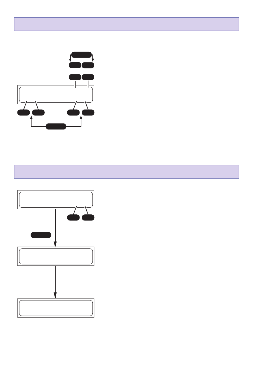
Programme de cyclage NiCd
ENTER
INC
ou
DEC
________________NiCd-Cycl. C>D 1
C:2.5A D:1.00A
________________
+
INC
-
DEC
ENTER
+
INC
NiCd-Entladebalancier-Programm
NiCd Tension de
________________
balancer = 1.20V
________________
+
INC
START
________________**INFORMATION***
BALANCER CON.
________________
2
sec.
2
sec.
INC
DEC
DEC
DEC
Ce programme sert pour l’optimisation de la capacité et le
cyclage d’une batterie.
Fixer avec les touches INC ou DEC en haut et à droite si le
programme doit commencer avec la charge ou avec la
décharge.
Fixer ensuite le nombre de cycles de 1 à 5 (Avec par ex. 3
cycles, C:2,5 A D : 1,0 A l’accu sera chargé et déchargé
trois fois de suite). Le programme déchargera l’accu avec le
courant de décharge réglé sur la droite de l’affichage
(0,1…1,0 A) et le rechargera ensuite avec le courant de
charge réglé sur la gauche de l’affichage (0,1…5,0 A).
La coupure de fin de charge se fera selon la valeur réglée
-
pour la tension de coupure ’’Delta-Peak NiCd’’.
L’arrêt de la décharge se fait selon la tension finale de décharge
préréglée dans le programme de décharge NiCd.
Le déroulement de actuelle cycle est décrit dans le
paragraphe ‘’Indications de l’affichage’’.
Ce programme sert pour la coordination de la tension des
différents éléments pour les packs d’accus de 2-6 éléments.
Placer la tension de fin de décharge du Balance 1.20…1.30
V avec la touche INC ou DEC.
Avant la charge, les différents éléments d’un accu devront
être équilibrés afin qu’ils ne soient pas surchargés durant la
-
charge. Un accu doit être équilibré, particulièrement après
un long temps de charge
Pour cela, prise du Balancer devra être connectée.
En outre, tous les éléments doivent avoir une tension plus
haute que la tension de fin de décharge réglée du Balancer.
Pour obtenir la capacité maximum d’un accu, les différents
éléments devront être déchargés sous 1,20 V durant
quelques heures, mais au maximum pendant 24 h, avant
d’être mis en charge. Avec une tension en dessous de 1,20
V, les éléments de l’accu perdront de la capacité. C’est
pourquoi un accu devra être chargé à peu près à 60% de sa
capacité avant un long stockage.
Déch
DéchBLC 28:30 01425
________________
NC-3.00A 06.717V
________________
54
Le programme décharge un pack d’accus avec 50mA…1,0
A. Les éléments d’une plus forte tension seront
supplémentairement déchargés avec un courant d’env.
100mA (équilibrés).
Lorsque tous les éléments atteignent la tension de fin de
décharge du Balancer (+ 0.01 V), le processus de décharge
du Balancer est terminé.
Page 55

Coupure Delta Peak (-
∆∆
∆ Peak)
∆∆
________________NiCd Delta-Peak-
Tens.=10mV/elem.
________________
+
-
DECINC
La coupure de charge automatique
(Détection pleine charge de l’accu)
travaille selon le procédé Delta-Peak
des millions de fois éprouvé (appelé
aussi Delta-U ou Delta-V). Ces
Tension des éléments
Temps de charge
procédés valorisent la tension maximum de la courbe de
charge, laquelle calcule exactement l’atteinte de la charge
maximale.
Durant la charge, la tension de l’accu monte d’abord continuellement, avec l’accu plein l’augmentation
de la température assure à nouveau une légère diminution de la tension de la batterie. Cette
diminution sera déterminée et revalorisée.
La tension de la coupure automatique (en mV par élément) pourra être réglée pour les accus NiCd.
Le réglage d’une tension de 10…30 mV/élément s’est révélé être le mieux adapté. Une tension plus
élevée conduit le plus souvent à une surcharge de la batterie et une tension plus faible à une
coupure prématurée. La valeur la mieux adaptée pour l’accu à charger sera déterminée par des
essais de charge.
Pour ne pas surcharger un accu, commencer la charge avec une tension de coupure Delta-Peak
de 10mV.
12. Programme NiMH
NiMH
Programme
Automatique
MODE MODE MODE MODE MODE
NiMH
Programme
Manuel
NiMH
Programme
de décharge
NiMH
Programme
de cyclage
Programme de décharge du Balancer
MODE
NiMH
NiCd
Coupure
∆ ∆
∆
delta-peak
∆ ∆
Confortable programme pour la charge des accus Nickel-Métal-Hybrides couramment utilisés en
modélisme. Lorsque le programme de charge/décharge est terminé, l’inscription ‘’ENDE’’ (FIN)
apparaît sur l’affichage, avec le temps de charge, le dernier courant de charge/décharge, la
capacité emmagasinée/prélevée ainsi que la tension de l’accu jusqu’à la déconnexion de celui-ci.
Ces données donnent dans certaines circonstances de précieuses indications sur le comportement
de la charge, la capacité du pack d’accus NiMH connecté ou sur les détections pleine charge
erronées.
Programme automatique NiMH
________________ NiMH-Automatiqu
C:2.5A limite
________________
+
INC
-
DEC
Dans ce programme, le chargeur détecte le type d’accu
e
NiCd connecté et adapte le courant de charge en
correspondance, de sorte qu’une surcharge du pack d’accus
sera empêchée.
Le courant de charge maximal pourra être réglé de 0,1 A à
5,0 A avec les touches INC/DEC, sans limitation, avant la
connexion de l’accu.
La coupure de fin de charge se fera selon la valeur réglée
pour la tension de coupure ’’Delta-Peak NiMH’’.
55
Page 56
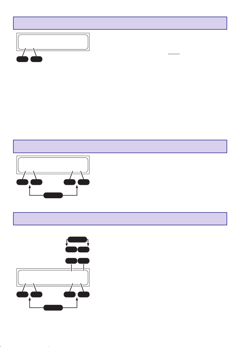
Programme manuel NiMH
________________NiMH-Manuel
C:2.5A
________________
+
-
DECINC
Programme de décharge NiMH
________________NiMH-Décharge
1.00A 4.8V
________________
+
INC
-
DEC
ENTER
+
INC
Avec ce programme, l’accu sera chargé avec le courant de
charge réglé.
Le courant de charge maximal pourra être réglé de 0,1 A à
5,0 A avec les touches INC/DEC, avant la
connexion de l’accu.
Observer les indications du fabricant des accus ! Ne charger
en aucun cas les accus sous plus de 2C !
Exemple : Courant de charge maximum 8,4 A pour les accus
NiMH 6N-4200, courant de charge rapide 4,2 A pour les
accus Graupner. Le courant de charge sera limité à 2 A au
maximum pour les accus d’émission.
La coupure de fin de charge se fera selon la valeur réglée
pour la tension de coupure ’’Delta-Peak NiMH’’.
Ce programme sert par ex. pour déterminer la capacité
restante ou pour définir la décharge d’un accu d’émission,
de réception ou de propulsion. Avec ce programme, le
courant de décharge réglé (0,1…1,0 A, à gauche sur
-
l’affichage) déchargera l’accu connecté jusqu’à la tension
DEC
de coupure de fin de décharge réglée (0,1…16,8 V, à droite
sur l’affichage). Une tension de décharge d’à peu près
1,0…1,2 V par élément sera
sélectionnée pour ne pas décharger trop profondément
l’accu et pour éviter une éventuelle inversion de polarité.
Programme de cyclage NiMH
ENTER
INC
DEC
________________NiMH-Cycl. C>D 1
C:2.5A D:1.00A
________________
56
+
INC
-
DEC
ENTER
+
INC
ou
Ce programme sert pour l’optimisation de la capacité et le
cyclage d’une batterie. Fixer avec les touches INC ou DEC en
haut et à droite si le programme doit commencer avec la
charge ou avec la décharge. Fixer ensuite le nombre de cycles
INC
de 1 à 5 (Avec par ex. 3 cycles, C:2,5 A D = 1,0 A l’accu
sera charge et décharge trois fois de suite). Le programme
DEC
déchargera l’accu avec le courant de décharge réglé sur la
droite de l’affichage (0,1…1,0 A) et le rechargera ensuite
avec le courant de charge réglé sur la gauche de l’affichage
(0,1…5,0 A). La coupure de fin de charge se fera selon la
valeur réglée pour la tension de coupure ’’Delta-Peak
-
NiMH’’.
DEC
L’arrêt de la décharge se fait selon la tension finale de décharge
préréglée dans le programme de décharge NiMH.
Le déroulement de actuelle cycle est décrit dans le
paragraphe ‘’Indications de l’affichage’’.
Page 57
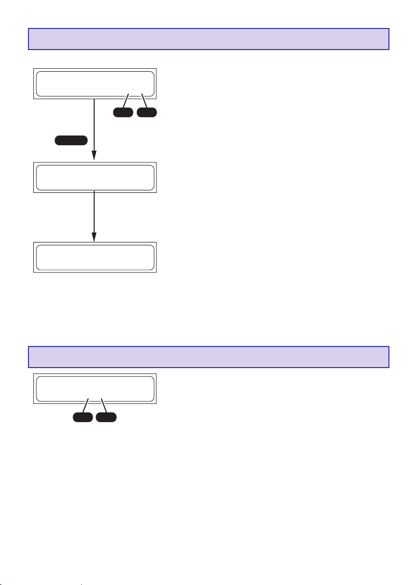
NiMH-Entladebalancier-Programm
NiCd Tension de
________________
balancer = 1.20V
________________
+
INC
DEC
START
________________**INFORMATION***
BALANCER CON.
________________
2
sec.
2
sec.
Ce programme sert pour la coordination de la tension des
différents éléments pour les packs d’accus de 2-6 éléments.
Placer la tension de fin de décharge du Balance 1.20…1.30
V avec la touche INC ou DEC.
Avant la charge, les différents éléments d’un accu devront
être équilibrés afin qu’ils ne soient pas surchargés durant la
-
charge. Un accu doit être équilibré, particulièrement après
un long temps de charge
Pour cela, prise du Balancer devra être connectée.
En outre, tous les éléments doivent avoir une tension plus
haute que la tension de fin de décharge réglée du Balancer.
Pour obtenir la capacité maximum d’un accu, les différents
éléments devront être déchargés sous 1,20 V durant
quelques heures, mais au maximum pendant 24 h, avant
d’être mis en charge. Avec une tension en dessous de 1,20
V, les éléments de l’accu perdront de la capacité. C’est
pourquoi un accu devra être chargé à peu près à 60% de sa
capacité avant un long stockage.
Déch
DéchBLC 28:30 01425
________________
NM-3.00A 06.717V
________________
Coupure Delta-Peak (-
________________NiMH Delta-Peak-
Tens.= 5mV/elem.
________________
+
-
DECINC
Le programme décharge un pack d’accus avec 50mA…5,00
A. Les éléments d’une plus forte tension seront
supplémentairement déchargés avec un courant d’env.
100mA (équilibrés).
Lorsque tous les éléments atteignent la tension de fin de
décharge du Balancer (+ 0.01 V), le processus de décharge
du Balancer est terminé.
∆∆
∆ Peak)
∆∆
La tension d’intervention (en mV par élément) de la coupure
automatique pour les accus NiMH pourra être réglée.
Les accus NiMH ont une perte de tension plus faible par
comparaison aux accus NiCd. Le réglage d’une tension de
5…25 mV/élément s’est révélé être le mieux adapté. Une
tension plus élevée conduit le plus souvent à une surcharge
de la batterie et une tension plus faible à une coupure
prématurée.
La valeur la mieux adaptée pour l’accu à charger sera
déterminée par des essais de charge.
Pour ne pas surcharger un accu, commencer la charge avec
une tension de coupure Delta-Peak de 5mV.
57
Page 58
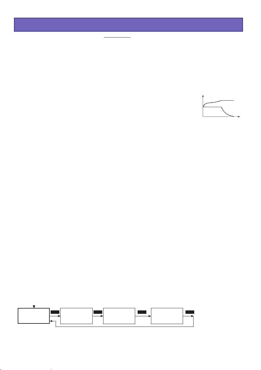
13. Programme Lithium
Ce programme de charge est adapté uniquement pour la charge et la décharge des accus au
LiFePO4 (LiFe) avec une tension de 3,3 V/élément, des accus au Lithium-Ion avec une tension
de 3,6 V/élément, des accus au Lithium-Polymer et au Lithium-Manganèse avec une tension de
3,7 V/élément. Les accus au Lithium se distinguent surtout par une plus forte capacité, par
comparaison aux autres types d’accus. Ce gros avantage nécessite cependant d’autres
méthodes de traitement en ce qui concerne la charge et la décharge ainsi que pour une
utilisation sans danger. Les prescriptions de base données ici devront être observées dans tous
les cas. Les autres indications correspondantes et les conseils de sécurité sont à relever dans
les données techniques du fabricant des accus.
En principe, les accus au Lithium devront être chargés UNIQUEMENT avec
des chargeurs spéciaux qui sont réglés sur chaque type d’accu (Tension de
fin de charge, capacité). La charge se fait autrement que pour les accus NiCd
ou NiMH par une méthode dite Courant constant/Tension constante. Le courant
nécessaire pour la charge est donné par la capacité de l’accu et réglé
tension
courant
Temps de charge
automatiquement par le chargeur. Les accus au Lithium seront habituellement chargés avec un
courant 1C (Courant de charge 1C = Intensité du courant de charge. Exemple : avec une capacité
par ex. de 1500 mAh, le courant de charge correspondant 1C = 1500 mA (1,5 A). En outre, la
capacité de l’accu est réglée par le chargeur à la place du courant de charge. Lorsque la capacité
de fin de charge spécifique à chaque type d’accu est atteinte, le chargeur réduit automatiquement
le courant de charge pour empêcher qu’elle soit dépassée. Si le fabricant de l’accu indique un
courant de charge plus faible que 1C, le courant de charge devra aussi être réduit en correspondance.
Pour obtenir une charge optimale avec une plus longue durée de vie et une plus haute
sécurité, nous conseillons vivement de connecter la prise du Balancer sur le chargeur pour
la charge et la décharge.
Problèmes avec un mauvais traitement des accus
Une surcharge des accus au Lithium est très dangereuse, car celle peut conduire à un dégagement
de gaz, à une surchauffe et même à l’explosion des éléments. Si la tension de fin de charge de 3,6V
/ élément (LiFe), 4,1 V/élément (Lithium-Ion) et de 4,2 V/élément (Li-Po/Li-Mn) est dépassée de plus
de 1%, une conversion du Lithium-Ion en Lithium métallique commence à se produire dans les
éléments. Celle-ci réagit cependant en liaison avec l’eau contenue dans l’électrolyse très violente
qui provoque l’explosion des éléments. D’autre part, si la tension de fin de charge est dépassée, les
éléments des accus Lithium-Ion présenteront une capacité beaucoup plus faible. Une tension de
0,1 V en-dessous du seuil signifie déjà une perte de capacité d’à peu près 7%. La décharge
profonde des accus au Lithium conduit à une rapide perte de capacité. Cet effet n’est pas irréversible
tant que l’on évitera de décharger les accus sous une tension en-dessous de 2,5 V/élément.
Attention : Le type des éléments réglés, leur capacité et leur nombre devront toujours être
accordés à l’accu à charger et ne devront jamais varier ; Danger d’explosion ! Aucun accu avec
dispositif de charge intégré ne devra être connecté. Charger les accus au Lithium uniquement sur
une base non combustible.
Lithium
Programme
58
Manuel
Lithium
MODE MODE MODE
Programme
de décharge
Lithium
Stockage
Lithium
Sélection du
type
MODE
Page 59

Programme manuel Lithium
________________LiPo-Manuel
C:4.0 A 4000mAh
________________
+
INC
Pour la charge, nous conseillons vivement de connecter la prise du Balancer pour des
raisons de sécurité !
Lorsque l’accu est relié au chargeur et que le processus de charge est démarré, le courant de
charge commence avec C, 00A et augmente lentement vers la limitation réglée. Cependant, ne pas
s’étonner si le courant de charge que l’on a réglé n’est pas atteint, car le programme de charge
surveille en permanence la tension de la batterie pour empêcher ainsi un gonflement de l’accu, tant
que la tension des éléments d’un pack est égale. La diminution automatique du courant de charge
sera interrompue par l’inscription ‘’FIN’’ apparaissant sur l’affichage, avec l’indication du courant de
charge réduit.
DEC
-
ENTER
+
INC
-
DEC
Avec ce programme, l’accu sera chargé avec le courant de
charge réglé.
Avant de connecter l’accu à charger, le courant de charge
(0,1…5,0 A, à gauche sur l’affichage) sera réglé avec les
touches INC/DEC et après avoir pressé la touche ENTER,
la capacité de l’accu (50…9900 mAh, à droite sur l’affichage)
sera réglé avec les touches INC/DEC. Avec un dépassement
de 10% de la capacité réglée, le processus de charge sera
interrompu pour des raisons de sécurité..
Programme de décharge Lithium
________________LiPo-Décharge
1.00A 2.5V/elem.
________________
+
INC
-
DEC
ENTER
+
DECINC
Ce programme sert par ex. pour déterminer la capacité
restante d’un accu au Lithium non entièrement vide.
Avec ce programme, le courant de décharge réglé (0,1…1,0
A, sur la gauche de l’affichage) déchargera l’accu jusqu’à la
-
tension de coupure réglée (2,5…3,7 V/élément, sur la droite
de l’affichage). Une tension de 2,5 V par élément ne devra
pas être sous-dépassée, car autrement l’accu pourra être
détérioré.
________________LiPo stockage
________________
2
sec.
________________<2.0A
________________
+
INC
-
DEC
3.80V/é
+
ENTER
Lithium-stockage
Ce programme sert pour charger ou décharger les accus
afin d’obtenir le meilleur état de charge possible pour le
stockage.
Avec ce programme l’accu sera amené sur la tension de
stockage réglée par une charge ou une décharge et pourra
ainsi être stocké pendant plus longtemps.
Tensions de stockage optimales :
LiPo: 3,8...3,9V/Elément
-
DECINC
LiIo: 3,7...3,8V/Elément
LiFe: 3,3...3,4V/Elément
59
Page 60

Nombre d‘ éléments Lithium
Après avoir connecté le Pack d’accus sur le charger et
________________
*éléments LiPo*
2élém. ( 7.73V)
________________
+
INC
Attention ! Fixer absolument le bon
nombre d’éléments, car autrement
l’accu pourra exploser et prendre feu !
DEC
-
avoir pressé la touche START durant env. 2 sec., l’affichage
*
avec le nombre d’éléments Lithium apparaît, lequel sera
automatiquement détecté avec 1-2 éléments. A partir de 2
éléments, il faudra fixer manuellement le nombre d’éléments
avec les touches INC/DEC, car une détection automatique
n’est plus possible à partir de 3 éléments. La tension du
pack d’accus connecté est visible pour contrôle sur le côté
droit de l’affichage. Le processus de charge est démarré
par une autre pression sur la touche START.
Programme de sélection des types Lithium
________________
Lithium Type
LiPo
________________
+
INC
-
DEC
(LiPo, Lilo ou LiFe) influence la tension de coupure. Si un accu au Lithium n’est rechargé qu’au 2/3
de sa capacité, c’est qu’un mauvais type d’accu a été réglé.
Attention : Lorsqu’une fausse valeur est réglée ici, l’accu pourra être détérioré et risquera même
d’exploser !
C’est le programme de réglage le plus important pour les
accus au Lithium. Le type d’accu sera déterminé dans
cette sélection. Celui-ci sera soigneusement réglé et vérifié,
car le chargeur travaille sur tous les autres paramètres de
charge pour ces réglages. Le réglage des types d’accus
Les types d’accus seront indiqués comme suit pour la charge:
LiPo (LiMn) = LP
LiIo = LI
LiFe = LF
14. Programme Pb
Pb
Programme
Manuel
MODE MODE
Ce programme est uniquement adapté pour la charge et la décharge des accus au plomb avec
électrolyse liquide et gélifiée avec exactement 2, 4, 6 et 12 V et 1, 2, 3, 6 éléments.
Attention : Les batteries au plomb avec une autre tension nominale ne seront pas détectées par le
chargeur et ne devront pas être connectées sur celui-ci.
Les accus au plomb se comportent très différemment des accus NiCd ou NiMH. En ce qui concerne
la capacité, les accus au plomb sont seulement chargeables avec des courants relativement
faibles par comparaison aux accus NiCd ou NiMH. Ceci est aussi valable surtout pour leur recharge indiquée par les fabricants d’au moins 14 à 16 heures pour atteindre leur capacité, avec un
courant de charge normal. Le courant de charge normal se calcule au 10
de l’accu. Exemple : Capacité de l’accu = 12 Ah à Courant de charge normal =1,2 A. La détection
pleine charge se fait (autrement qu’avec les accus NiCd ou NiMH) typiquement par la hauteur de
la tension de l’accu.
60
Pb
Programme
de décharge
ème
de la capacité nominale
Page 61
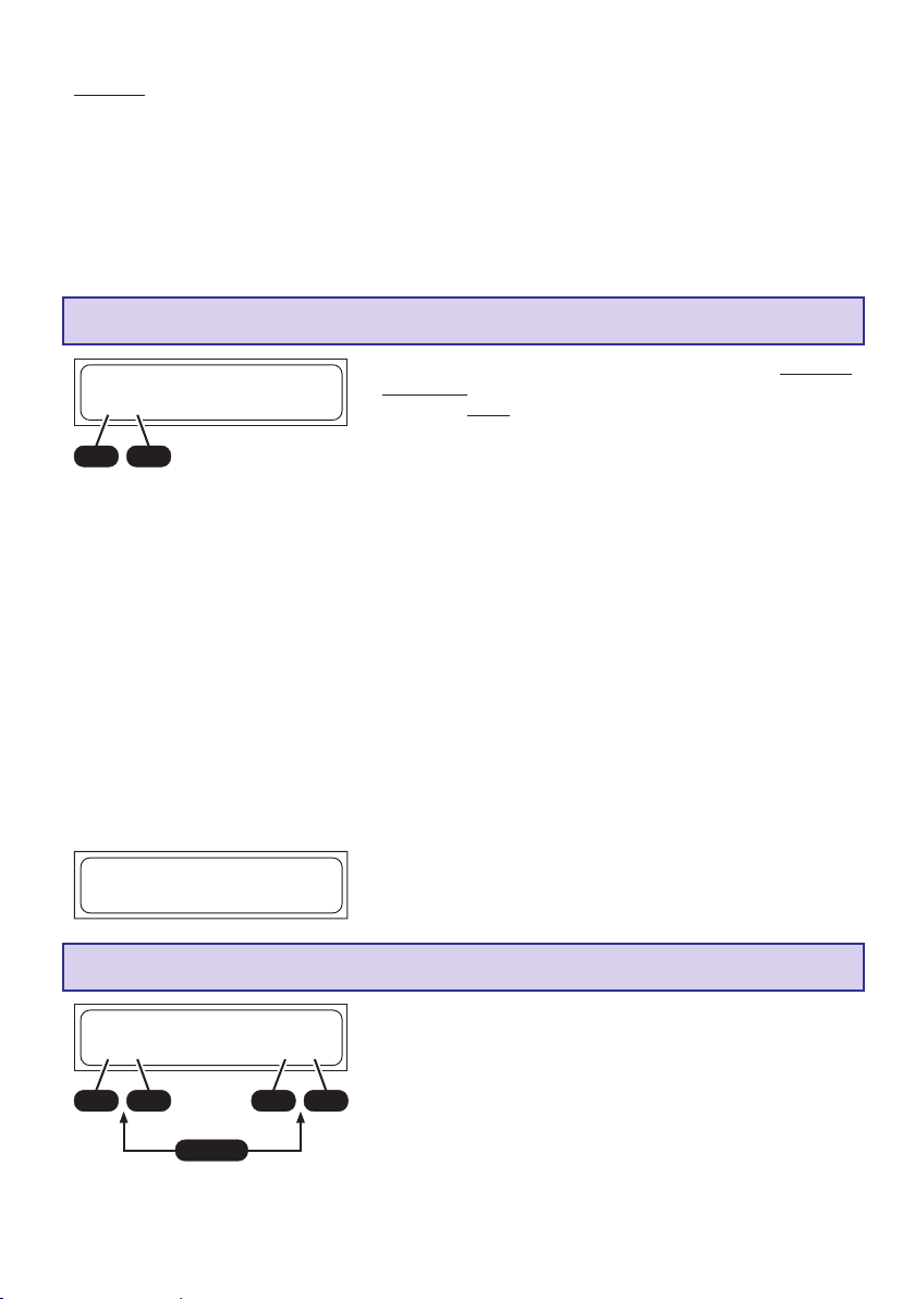
Attention : Las batteries au plomb ne sont pas aptes à la charge rapide. Pour cette raison, respecter
toujours le courant de charge conseillé par le fabricant. Penser aussi à la capacité nominale.
La durée de vie d’un accu Pb sera négativement influencée très rapidement par un mauvais
entretien (Surcharges, nombreuses décharges à 100%, et particulièrement les décharges
profondes). La hauteur du courant de charge/décharge sera aussi décidée par la capacité prélevable
de la batterie. Plus haut sera le courant, plus faible sera le rendement de capacité.
Le retardement pour la coupure de charge dans les réglages de l’utilisateur, les valeurs réglées et
le Timer de sécurité n’ont aucun effet dans les programmes Pb.
Programme manuel Pb
________________Pb-Manuel
C:2.5A
________________
+
Si le fabricant de l’accu indique un plus faible courant de charge, celui-ci devra aussi être limité, car
autrement le chargeur pourrait régler un plus haut courant en raison d’une bonne docilité de charge
de l’accu.
Lorsque l’accu a été connecté sur le chargeur et que le processus de charge a été démarré, le
courant de charge commence à monter lentement de 0,00 A jusqu’à la limitation réglée. L’accu sera
à nouveau mesuré et le courant de charge sera adapté aux données. Le programme de charge
détermine automatiquement le nombre d’éléments de l’accu en fonction de son état de tension.
Ne pas cependant s’étonner si le courant de charge réglé n’est pas atteint, car le programme de
charge surveille en permanence la tension de l’accu pour empêcher ainsi une surcharge .
L’accu se chargé avec les courants maximum possibles seulement jusqu’à l’atteinte d’une tension
de 2,3 à 2,35 Volts par élément. Un passage se fait ensuite sur une pleine charge ménagée. Le
courant de charge sera à nouveau réduit pour atteindre un plus haut degré de remplissage possible
de l’accu. La terminaison du processus de charge se fait automatiquement à l’atteinte d’une tension
d’env. 2,45 à 2,5 Volts par élément.
Grâce à l’adaptation automatique du courant de charge, une charge plus rapide et nettement moins
longue qu’avec les 14 à 16 heures habituelles est possible.
-
DECINC
________________
CHG 367 :0 9 04448
FIN
Pb 0mA 2.147V
________________
Avec ce programme, le courant de charge maximal
admissible pour l’accu à charger sera réglé avec les touches
INC/DEC, avant sa connexion sur le chargeur.
Ce réglage place seulement la limite supérieure, car le
chargeur doit sonder l’accu.
Lorsque le processus de charge est terminé, un signal
acoustique se fait entendre avec certains intervalles de
temps. Parallèlement à cela, l’inscription ‘’FIN’’ apparaît
sur l’affichage.
Programme de décharge Pb
________________Pb-Décharge
1.00A 12.0V
________________
+
INC
-
DEC
ENTER
+
Ce programme sert par ex. pour déterminer la capacité
restante d’un accu de propulsion.
Avec ce programme, l’accu sera déchargé avec le courant
de décharge réglé (0,1…1,0 A, à gauche sur l’affichage)
-
DECINC
jusqu’à la tension de décharge réglée (1,7…12 V , à droite
sur l’affichage). Pour une mesure de capacité valable, le
courant de décharge devra être situé largement en dessous
de 1C (Capacité de l’accu = 2 Ah à C = 2 A) et la tension de
fin de décharge sera sélectionnée à peu près à 1,7 V par
élément.
61
Page 62
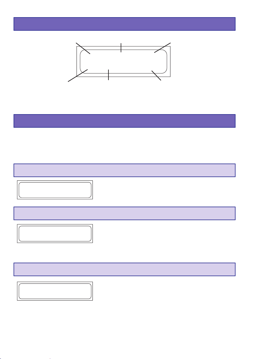
15. Indications de I‘affichage
Programme
Type d‘accu
Durant la charge/décharge, des données importantes seront clairement lisibles sur l’affichage à
cristaux liquides à deux lignes jusqu’à la dé-connexion de l’accu. Avec la charge d’un autre accu,
les valeurs précédemment affichées ne seront plus appelables.
Temps de charge/décharge
(min.: sec.)
Man. 12:56 00321
________________
NC+4.50A 11,985V
________________
Courant de charge/décharge
Capacité (mAh)
Tension de I‘accu
16. Indications de contrôle sur I‘affichage
Le chargeur est équipé de nombreux dispositifs de protection et de surveillance pour le contrôle
des différentes fonctions et de l’électronique de l’appareil. Un dépassement des valeurs limites
conduit dans quelques cas à la coupure du processus de charge (Par ex. en cas de surtension, de
sur-température ou d’utilisation d’une batterie de voiture vide).
Ces causes d’erreur seront indiquées sur l’affichage avec l’intervention du vibreur.
Processus de mesure
________________MESURE DE I`ACCU
ATTENDEZ S.V.P..
________________
Après avoir pressé la touche START durant env. 2 sec.,
l’accu sera mesuré de sorte que cet avertissement
apparaîtra sur l’affichage durant 1 à 2 sec. avant que le
processus de charge soit démarré.
Advertissement de fin de charge
FIN
________________
CHG 48:32 03363
NC 200mA 9.773V
________________
Lorsqu’un programme de charge/décharge est terminé,
l’inscription ‘’FIN’’ s’échange avec la désignation du
programme sur l’affichage. Le vibreur intégré émet en
même temps un signal acoustique pour un temps limité.
Indication lorsque la prise du Balancer est connectée
________________BLC 28:30 02850
Man.
LP+6.00A 14.717V
________________
62
Si la prise du Balancer de l’accu est reliée au chargeur et
que le Balancer est ainsi activé, BLC apparaît en haut et à
gauche sur l’affichage en s’échangeant avec la désignation
du programme.
Page 63
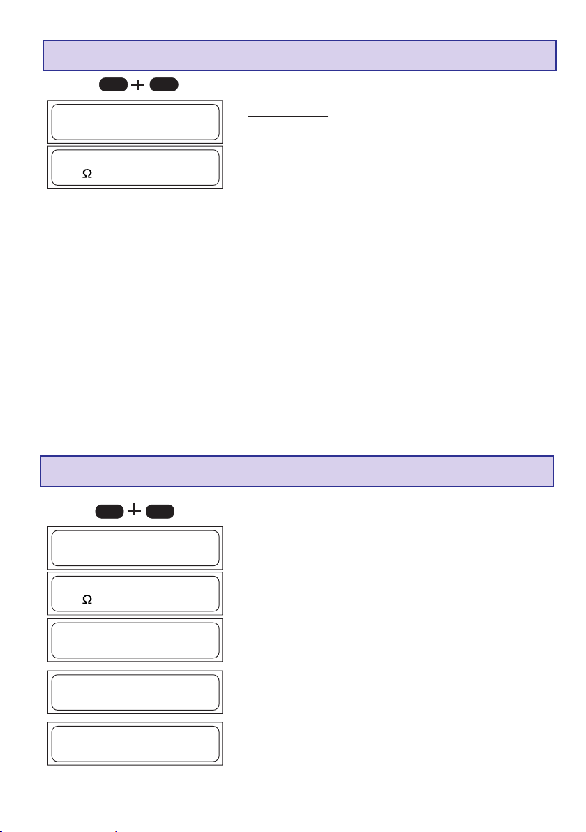
Affichage de la tension d‘ entrée et de rés. d‘accu
DECINC
________________TENSION D´ENTRÉE
13,62V
________________
________________ RÉS. D ´ ACCU
________________
25m
L’indication de la résistance interne permet le contrôle de la qualité de l’accu. La résistance
interne sera mesurée durant la charge/décharge après 1...10 minutes. Retournez dans le menu
par une pression de touche quelconque.
Le tension d’entrée et la résistance actuelles de l’accu
pourront être appelées à tout moment en pressant
simultanément les touches INC et DEC. Par la pression
des touches INC ou DEC, l’affichage s’échange pour la
résistance interne, les tensions séparées d’éléments ou
pour la tension d’entrée.
L’indication de la tension d’entrée est surtout très utile
lorsqu’une batterie de voiture est utilisée comme source
de courant.
Indication des tensions séparées d’éléments
DECINC
________________TENSION D´ENTRÉE
13,62V
________________
________________ RÉS. D ´ ACCU
________________
25m
]]]]]]]]
________________1.
]]]] 4.153V
]]]]]]]]
]]]]]]]]
________________
2.
________________3.
________________
4. 0.000V
________________5. 0.000V
________________
6. 0.000V
]]
]]]]
] 4.168V
]]]]]]]]
]]
]]]]]]
]]] 4.053V
]]]]]]
La tension d’entrée actuelle et la résistance interne de l’accu
pourront être appelées à tout moment par la pression
simultanée des touches INC et DEC. Par la pression des
touches INC ou DEC, l’affichage s’échange pour la
résistance interne, les tensions séparées d’éléments ou
pour la tension d’entrée.
L’affichage des tensions séparées d’éléments sert pour la
vérification des différentes tensions d’éléments (1-6
éléments).
63
Page 64

17. Avertissements d‘erreur
Le chargeur est équipé d’une multitude de réglages de protection et de surveillance pour
le contrôle de chacune des fonctions et de l’électronique de l’appareil. Un dépassement des valeurs
limites conduit dans certains cas à la réduction automatique des réglages de l’appareil (par ex.
courant de charge et de décharge) ou à l’arrêt du processus de charge (par ex. batterie de voiture se
vidant). En cas d’erreur, la cause sera indiquée sur l’affichage. La plupart des causes d’erreur sont
auto-explicatives. Les solutions qui vont suivre seront cependant utiles pour y remédier.
L’avertissement ainsi que le signal acoustique sont réglables avec la touche ‘’ENTER’’.
________________
*****ERREUR*****
Batt. voit. vide
________________
________________
*****ERREUR*****
Mauv. polarité
________________
________________
*****ERREUR*****
Interruption
________________
________________
*****ERREUR*****
Tps.chg. dépassé
________________
________________
*****ERREUR*****
Tension dépassé
________________
Cet avertissement apparaît en cas de sous-dépassement
de la tension de la batterie de voiture dans
les réglages de l’utilisateur (Par es. 11,0 V).
Cet avertissement apparaît lorsque l’accu a été connecté
sur le chargeur avec une inversion des polarités.
Cet avertissement est donné lorsqu’une interruption se
produit dans la liaison entre l’accu et le chargeur durant
une charge/décharge.
Si cet avertissement se produit durant le fonctionnement,
cela peut être dû à un contact intermittent.
Note : Cet avertissement d’erreur est aussi donné lorsque
la charge est interrompue par ex. en déconnectant le
cordon de charge.
Si le Timer interne de sécurité de charge intervient, une
interruption du processus en cours se fait par sécurité.
Le Timer de sécurité est réglé fixement sur 180 min. pour
les accus NiCd/NiMH, sur 180 min.pour les accus au
Lithium et il est désactivé pour les accus au plomb ; ces
réglages ne pourront pas être modifiés.
Causes possibles : Courant de charge trop faible ; l’accu
ne sera pas totalement chargé, cordon de charge de trop
faible section et trop long ; le courant de charge ne peut
pas suffisamment passer, capacité de l’accu trop forte.
Cet avertissement apparaît si le chargeur débite une tension
trop élevée, par ex. par un mauvais réglage du nombre
d’éléments au Lithium ou d’un accu au plomb.
En outre, cet avertissement d’erreur peut apparaître en cas
de surcharge des éléments connectés.
________________
*****ERREUR*****
Tens. trop basse
________________
64
Cet avertissement apparaît si le chargeur débite une
tension trop faible, par ex. par un mauvais réglage du
nombre d’éléments au Lithium ou d’un accu au plomb.
La raison de cet avertissement d’erreur est que les
éléments ont été trop profondément déchargés par
un mauvais réglage.
Page 65

________________
*****ERREUR*****
Tens.bal.dépassé
________________
Si le chargeur envoi une trop haute tension par élément sur
l’entrée du Balancer, il apparaît cet avertissement d’erreur.
Cet avertissement apparaît avec les tensions suivantes :
LiPo > 4,3 V, Lilo > 4,2 V, LiFe > 3,9 V, NiCd/NiMH > 2,0 V
Cet avertissement peut en outre apparaître avec une
surcharge des éléments connectés.
________________
*****ERREUR*****
T.bal.trop basse
________________
________________
*****ERREUR*****
BALANCER N. CON
________________
Si le chargeur envoi une trop faible tension par élément sur
l’entrée du Balancer, il apparaît cet avertissement d’erreur.
Cet avertissement apparaît avec les tensions suivantes :
LiPo > 2,75 V, Lilo > 2,75 V, LiFe > 2,0 V, NiCd/NiMH > 0,1 V.
Dans ce cas, il est conseillé de charger l’accu durant
quelques minutes (max. 5 min.) dans le mode de programme
LiFe de façon à ce qu’une tension de 2 V par élément soit
obtenue, sans la connexion du Balancer.
Avertissement : Ceci peut causer une détérioration des
éléments et le pack d’accus devra être chargé
uniquement sous une rigoureuse surveillance. Dès que
la tension est à nouveau suffisamment haute, l’accu
devra absolument être chargé avec la prise du Balancer
connectée, pour des raisons de sécurité (danger
d’explosion et d’incendie !).
Si le programme de décharge NiCd/NiMH est démarré, sans
que la prise du Balancer soit connectée, cet avertissement
.
apparaîtra.
Su la prise du Balancer est déconnectée durant un
processus de charge ou de décharge, cet avertissement
apparaîtra de même.
18. Interface PC
Charger avec www.gm-racing.de dans la plage de téléchargement du logiciel ou avec
www.graupner.de le conducteur USB correspondant CP210x_Drivers.exe pour ce chargeur.
Connecter le cordon USB dans l’interface PC du chargeur. Relier le cordon USB à une interface
USB libre sur le PC.
Un :logiciel PC oeut être chargé sous www.graupner.de, www.gm-racing.de or
www.logview .info.
Avec ce logiciel des courbes peuvent être affichées et beaucoup plus.
65
Page 66

19. Nettoyage et entretien
Ce chargeur travaille sans entretien et nécessite aucune surveillance particulière. Dans votre
propre intérêt, protégez-le cependant de la poussière, des salissures et de l’humidité !
Pour nettoyer le chargeur, déconnectez-le de la batterie de voiture et de l’accu et essuyez-le avec
un chiffon doux et sec (N’utilisez aucun produit de nettoyage !).
20. Conseils pour I‘entretien des accus
• La charge des éléments seuls NiCd ou NiMH ou des batteries avec 1…4 éléments déclenche
à temps la coupure automatique, car ici la tension Peak n’est pas très nette et une fonction
impeccable ne peut pas être garantie. La coupure automatique peut ne pas intervenir, ou non
correctement. Pour cette raison, surveiller par plusieurs essais de charge si une coupure peut
se faire impeccablement avec l’accu à charger.
• Une batterie tiède délivre davantage de puissance qu’une froide ; il ne faut donc pas s’étonner qu’une
batterie soit moins performante en hiver.
• Les surcharges comme les décharges profondes conduisent à une détérioration irréparable des
éléments, elles diminuent la durée de vie et la capacité des accus.
• Ne jamais stocker trop longtemps des accus non chargés, vides ou seulement en partie chargés.
Charger les accus avant de les stocker et vérifier leur état de charge de temps en temps.
• Lors de l’achat d’un accu, veiller à sa bonne qualité, charger d’abord un accu neuf seulement avec
de faibles courants et ensuite peu à peu avec des courants plus forts.
• Charger toujours un accu juste avant son utilisation, il délivrera ainsi davantage de puissance.
• Ne jamais souder directement sur les accus, car l’augmentation de température détériorera
l’étanchéité et la valve de sécurité des éléments, ils perdront en outre de l’électrolyse, ou elle
séchera et leur capacité sera fortement diminuée.
• Les forts courants de charge et de décharge raccourcissent la durée de vie des accus ; respecter
absolument les prescriptions du fabricant des accus.
• Les forts courants de charge ne conviennent pas aux accus au plomb ; ne jamais dépasser le
courant de charge indiqué par le fabricant de l’accu.
• Protéger les accus des vibrations et ne pas les soumettre à des petites charges mécaniques.
• Il peut se produire un dégagement de gaz (Hydrogène) durant la charge et l’utilisation des accus;
veiller à une bonne aération.
• Ne jamais mettre les batteries en contact avec l’eau ; Danger d’explosion
• Ne jamais mettre les batteries au Lithium en court-circuit ; Danger d’explosion !
• Note : Les accus peuvent exploser ou s’enflammer à la suite d’une défectuosité. Pour cette raison,
nous conseillons de charger tous les accus LiPo ainsi que les accus NiCd et NiMH dans un coffret
de sécurité, Réf. N°8370 ou 8371.
• Ne jamais ouvrir les éléments des batteries ; Danger de corrosion !
• Les packs d’accus NiCd ou NiMH seront cyclés de préférence en déchargeant d’abord séparément
tous les éléments et en rechargeant ensuite le pack d’accus complet. La décharge se fera avec
le chargeur (Elément après élément).
• Ne pas s’étonner si un pack d’accus accepte mieux la charge en été qu’en hiver ; un élément froid
n’est pas aussi réceptif au courant qu’un tiède.
• Conseil pour le débarras des batteries : Les batteries usagées ne devront pas être jetées dans
une poubelle domestique. Le détaillant chez qui la batterie a été achetée est obligé de tenir à
disposition un container pour la récupération des batteries usagées en vue de leur recyclage.
66
Page 67

21. Caractéristiques techniques
Accu:
Courant de charge / Puissance 100 mA jusqu à 5,0 A / max. 50 W avec courant sector 11...15V DC
connecteur
Courant de décharge / Puissance 100 mA jusqu à 1 A / max. 5 W
Accus NiCd et NiMH:
Nombre d‘éléments 1 - 14 éléments
Capacité à partir de 0,1 Ah jusqu à 9,9 Ah
Accus au Lithium:
Nombre d‘éléments 1-6 éléments
Tension des éléments 3,3 V (LiFe), 3,6 V (LiIo) et 3,7 V (LiPo/LiMn)
Capacité ab 0,1 Ah jusqu à 9,9Ah
Accus Pb:
Nombre d‘éléments 1, 2, 3, 6
Tension des accus 2, 4, 6, 12 V
Capacité à partir de 1 Ah
Particularités:
Plage de tensions d‘alimentation DC 11,0 jusqu à 15 V
Plage de tensions d‘alimentation AC 100~240V
Batterie de voiture nécessaire 12 V, 40 Ah min.
Batterie de voiture nécessaire 12-14V, min. 5 A stabilisé
Consommation à vide env. 0,1 A
Coupure en sous-tension, env. 11,0 V
Raccordement Balancer 1…6 Eléments NiMH/NiCd/LiPo/LiFe
Courant max. Balancer, env. NiMH/NiCd : 0,1 A, iPo/Lilo/LiFe : 0,3 A
Poids, env. 210 g
Dimensions (Lxlxh) 123 x 85 x 28 mm
1)
Toutes les données sont calculées sur une tension de batterie de voiture de 12,7 V
Les valeurs indiquées sont des valeurs indicatives qui peuvent varier en fonction de l’état de l’accu utilisé, de la température, etc…
1)
Indications quant à la protection de l’environnement
Ce produit à la fin de sa durée de vie ne doit pas être mis à la poubelle, mais être remis à une
collecte pour le recycle ment d’appareils électriques et électroniques. Le symbole inscrit sur le
produit, dans la notice d’instructions et sur son emballage l’indique.
Les matériaux selon leurs reconnaissances sont réutilisables. Avec le recyclage de matériaux et
autres formes d’appareils, vous contribuez à la protection de l’environnement.
Les batteries et accus doivent être retirés de l’appareil et doivent être remis à un dépôt
homologué pour ce type de produits.
Pour les modèles radiocommandés, les pièces électroniques, comme par exemple les servos,
récepteur ou variateur de vitesse, doivent être démontés et retirés du produit et être remis à
une collecte spécialisée pour produits électroniques.
Veuillez s.v.p. demander auprès de votre mairie l’adresse exacte du point de récupération le plus
proche de chez vous.
67
Page 68
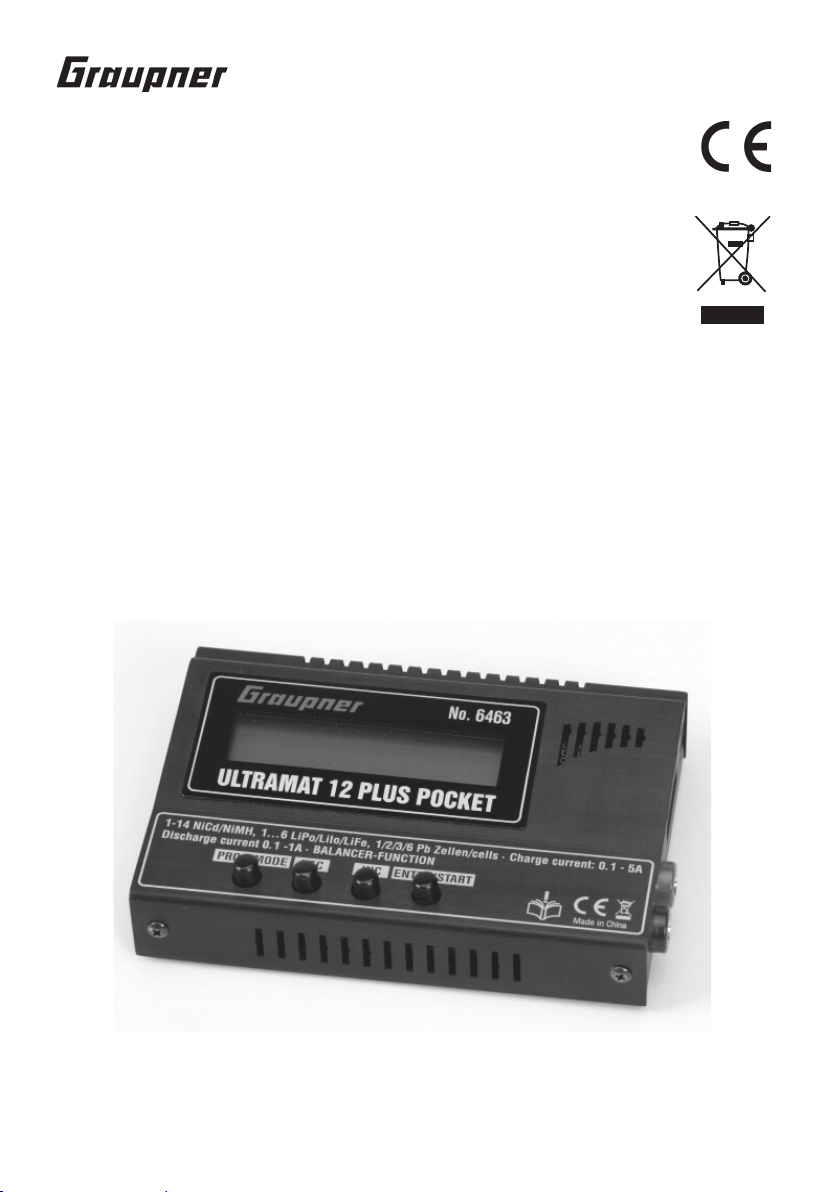
Art. n. 6463
INSTRUZIONI PER L`USO
ULTRAMAT 12 PLUS
POCKET CHARGER
Caricabatterie di grandi prestazioni, rapido, computerizzato
per la carica, la scarica e la formattazione di celle NiCd / NiMH,
LiPo / LiIo / LiMn / LiFe e al Piombo
Corrente di carica fino a 5 A ,
di scarica fino a 1 A
Equilibratore integrato per accumulatori
al Litio ed accumulatori NiMH/NiCd
G R A U P N E R GmbH & Co. KG D - 7 3 2 3 0 K I R C H H E I M / T E C K G E R M A N Y
Nessuna responsabilità per errori di stampa! Ciriserviamo la possibilità di apportare modifiche!
68
PN.NL-01
Page 69

Capitolo Pagina
Indice
1 1
..
1
1 1
2. 2.
2.
2. 2.
3. 3.
3.
3. 3.
4. 4.
4.
4. 4.
5. 5.
5.
5. 5.
6. 6.
6.
6. 6.
7. 7.
7.
7. 7.
8. 8.
8.
8. 8.
9. 9.
9.
9. 9.
10.10.
10.
10.10.
11.11.
11.
11.11.
12.12.
12.
12.12.
13.13.
13.
13.13.
14.14.
14.
14.14.
15.15.
15.
15.15.
16.16.
16.
16.16.
17.17.
17.
17.17.
18.18.
18.
18.18.
19.19.
19.
19.19.
20.20.
20.
20.20.
21.21.
21.
21.21.
GeneralitàGeneralità
.
Generalità
..
GeneralitàGeneralità
Precauzioni e avvertenze per la sicurezzaPrecauzioni e avvertenze per la sicurezza
Precauzioni e avvertenze per la sicurezza
Precauzioni e avvertenze per la sicurezzaPrecauzioni e avvertenze per la sicurezza
Notizie generali per il funzionamentoNotizie generali per il funzionamento
Notizie generali per il funzionamento
Notizie generali per il funzionamentoNotizie generali per il funzionamento
Cavi di ricarica consigliati, polaritàCavi di ricarica consigliati, polarità
Cavi di ricarica consigliati, polarità
Cavi di ricarica consigliati, polaritàCavi di ricarica consigliati, polarità
Componenti del caricabatterie, utilizzo, avvio della caricaComponenti del caricabatterie, utilizzo, avvio della carica
Componenti del caricabatterie, utilizzo, avvio della carica
Componenti del caricabatterie, utilizzo, avvio della caricaComponenti del caricabatterie, utilizzo, avvio della carica
Programmi di carica e scaricaProgrammi di carica e scarica
Programmi di carica e scarica
Programmi di carica e scaricaProgrammi di carica e scarica
Struttura del programmaStruttura del programma
Struttura del programma
Struttura del programmaStruttura del programma
Scelta del gruppo di programmi di caricaScelta del gruppo di programmi di carica
Scelta del gruppo di programmi di carica
Scelta del gruppo di programmi di caricaScelta del gruppo di programmi di carica
Prima di cominciarePrima di cominciare
Prima di cominciare
Prima di cominciarePrima di cominciare
Avvio del processo di carica / scaricaAvvio del processo di carica / scarica
Avvio del processo di carica / scarica
Avvio del processo di carica / scaricaAvvio del processo di carica / scarica
Programmi di carica per accumulatori al Nichel-Cadmio (NiCd)Programmi di carica per accumulatori al Nichel-Cadmio (NiCd)
Programmi di carica per accumulatori al Nichel-Cadmio (NiCd)
Programmi di carica per accumulatori al Nichel-Cadmio (NiCd)Programmi di carica per accumulatori al Nichel-Cadmio (NiCd)
Programmi di carica per accum. al Nichel-Idrato di metallo (NiMH)Programmi di carica per accum. al Nichel-Idrato di metallo (NiMH)
Programmi di carica per accum. al Nichel-Idrato di metallo (NiMH)
Programmi di carica per accum. al Nichel-Idrato di metallo (NiMH)Programmi di carica per accum. al Nichel-Idrato di metallo (NiMH)
Programmi di carica per accumulatori agli ioni di litio (LiIo) /Programmi di carica per accumulatori agli ioni di litio (LiIo) /
Programmi di carica per accumulatori agli ioni di litio (LiIo) /
Programmi di carica per accumulatori agli ioni di litio (LiIo) /Programmi di carica per accumulatori agli ioni di litio (LiIo) /
polimeri di litio (LiPo) / LiMn / polimeri di litio (LiPo) / LiMn /
polimeri di litio (LiPo) / LiMn /
polimeri di litio (LiPo) / LiMn / polimeri di litio (LiPo) / LiMn /
Programmi di carica per accumulatori al piombo (Pb)Programmi di carica per accumulatori al piombo (Pb)
Programmi di carica per accumulatori al piombo (Pb)
Programmi di carica per accumulatori al piombo (Pb)Programmi di carica per accumulatori al piombo (Pb)
Indicazioni del display, Indicazioni dei dati del cicloIndicazioni del display, Indicazioni dei dati del ciclo
Indicazioni del display, Indicazioni dei dati del ciclo
Indicazioni del display, Indicazioni dei dati del cicloIndicazioni del display, Indicazioni dei dati del ciclo
Indicazioni di controllo sul displayIndicazioni di controllo sul display
Indicazioni di controllo sul display
Indicazioni di controllo sul displayIndicazioni di controllo sul display
delle singole celledelle singole celle
delle singole celle
delle singole celledelle singole celle
Segnalazioni di errore e avvertenzeSegnalazioni di errore e avvertenze
Segnalazioni di errore e avvertenze
Segnalazioni di errore e avvertenzeSegnalazioni di errore e avvertenze
Interfaccia PCInterfaccia PC
Interfaccia PC
Interfaccia PCInterfaccia PC
Pulizia e manutenzionePulizia e manutenzione
Pulizia e manutenzione
Pulizia e manutenzionePulizia e manutenzione
Consigli sul trattamento degli accumulatoriConsigli sul trattamento degli accumulatori
Consigli sul trattamento degli accumulatori
Consigli sul trattamento degli accumulatoriConsigli sul trattamento degli accumulatori
Caratteristiche tecnicheCaratteristiche tecniche
Caratteristiche tecniche
Caratteristiche tecnicheCaratteristiche tecniche
Certificato di garanziaCertificato di garanzia
Certificato di garanzia
Certificato di garanziaCertificato di garanzia
LiFePOLiFePO
LiFePO
LiFePOLiFePO
(LiFe)(LiFe)
(LiFe)
(LiFe)(LiFe)
4 4
4
4 4
Visualizzazione delle tensioniVisualizzazione delle tensioni
Visualizzazione delle tensioni
Visualizzazione delle tensioniVisualizzazione delle tensioni
6969
69
6969
7070
70
7070
7171
71
7171
7272
72
7272
7272
72
7272
7373
73
7373
7373
73
7373
7474
74
7474
7474
74
7474
7575
75
7575
7676
76
7676
7878
78
7878
8181
81
8181
8383
83
8383
8585
85
8585
8585
85
8585
8787
87
8787
8989
89
8989
8989
89
8989
9090
90
9090
6767
67
6767
copertinacopertina
copertina
copertinacopertina
1. Notizie generali
Per poter utilizzare il vostro nuovo caricabatterie al massimo delle sue potenzialità,Per poter utilizzare il vostro nuovo caricabatterie al massimo delle sue potenzialità,
Per poter utilizzare il vostro nuovo caricabatterie al massimo delle sue potenzialità,
Per poter utilizzare il vostro nuovo caricabatterie al massimo delle sue potenzialità,Per poter utilizzare il vostro nuovo caricabatterie al massimo delle sue potenzialità,
prima di mettere in funzione l’apparecchio leggete attentamente queste descrizioni.prima di mettere in funzione l’apparecchio leggete attentamente queste descrizioni.
prima di mettere in funzione l’apparecchio leggete attentamente queste descrizioni.
prima di mettere in funzione l’apparecchio leggete attentamente queste descrizioni.prima di mettere in funzione l’apparecchio leggete attentamente queste descrizioni.
Osservate soprattutto le precauzioni e le avvertenze per la sicurezza. Queste istruzioniOsservate soprattutto le precauzioni e le avvertenze per la sicurezza. Queste istruzioni
Osservate soprattutto le precauzioni e le avvertenze per la sicurezza. Queste istruzioni
Osservate soprattutto le precauzioni e le avvertenze per la sicurezza. Queste istruzioniOsservate soprattutto le precauzioni e le avvertenze per la sicurezza. Queste istruzioni
devono essere conservate in un posto sicuro e consegnate ad un eventuale successivodevono essere conservate in un posto sicuro e consegnate ad un eventuale successivo
devono essere conservate in un posto sicuro e consegnate ad un eventuale successivo
devono essere conservate in un posto sicuro e consegnate ad un eventuale successivodevono essere conservate in un posto sicuro e consegnate ad un eventuale successivo
utente del caricabatterie.utente del caricabatterie.
utente del caricabatterie.
utente del caricabatterie.utente del caricabatterie.
Con l’ULTRAMAT 12 PLUS siete venuti in possesso di un prodotto completo con caratteristiche
eccezionali.
Con l’utilizzo della più moderna tecnologia elettronica e di un microprocessore RISC è stato
possibile ottenere eccezionali prestazioni per la ricarica, semplicità di utilizzo e una completa
affidabilità, riscontrabili solo in apparecchi notevolmente più costosi.
Con l’ULTRAMAT 12 PLUS potrete ricaricare quasi tutti gli accumulatori usati dai modellisti al
nichel cadmio (NiCd) sinterizzati, al nichel metal idrato (NiMH), ai polimeri di litio (LiPo), ai
LiFePO4 (LiFe), agli ioni di litio (LiIo), al litio-biossido di manganese (LiMn) e al piombo con gel o
acido. Questi accumulatori a tenuta di gas sono preferiti per l’utilizzo nel modellismo radiocomandato. Hanno una struttura robusta, non risentono della posizione e dei radiodisturbi. Per la
conservazione non richiedono particolari precauzioni ad eccezione di non lasciarli scaricare
completamente. Infine con l’ULTRAMAT è possibile scaricare e formattare gli accumulatori.
AvvertenzaAvvertenza
Avvertenza
AvvertenzaAvvertenza
Osservate sempre le indicazioni del produttore dell’accumulatore e rispettate la corrente ed il
tempo della carica. E’ possibile eseguire un carica rapida solo per gli accumulatori espressamente adatti a sopportare questa forte corrente di carica! Tenete presente che gli accumulatori
nuovi raggiungono la loro piena capacità solo dopo parecchi cicli di carica / scarica ed il
processo di carica può essere interrotto prima del tempo previsto. Eseguite parecchi test per
monitorare la sicura ed affidabile funzione dello spegnimento automatico del processo di carica
e del raggiungimento della completa capacità.
69
Page 70

2. Precauzioni e avvertenze per la sicurezza
Proteggete il caricabatterie dalla sporcizia, dall’umidità, dalla pioggia, dal calore intenso (perProteggete il caricabatterie dalla sporcizia, dall’umidità, dalla pioggia, dal calore intenso (per
Proteggete il caricabatterie dalla sporcizia, dall’umidità, dalla pioggia, dal calore intenso (per
Proteggete il caricabatterie dalla sporcizia, dall’umidità, dalla pioggia, dal calore intenso (perProteggete il caricabatterie dalla sporcizia, dall’umidità, dalla pioggia, dal calore intenso (per
es. dall’esposizione diretta ai raggi del sole) e dalle vibrazioni. Usatelo solamente in ambienties. dall’esposizione diretta ai raggi del sole) e dalle vibrazioni. Usatelo solamente in ambienti
es. dall’esposizione diretta ai raggi del sole) e dalle vibrazioni. Usatelo solamente in ambienti
es. dall’esposizione diretta ai raggi del sole) e dalle vibrazioni. Usatelo solamente in ambienties. dall’esposizione diretta ai raggi del sole) e dalle vibrazioni. Usatelo solamente in ambienti
asciutti!asciutti!
asciutti!
asciutti!asciutti!
Il caricabatterie non è adatto a ragazzi sotto i 14 anni. Non è un giocattolo!
Le griglie sull’involucro servono per il raffreddamento dell’apparecchio e non devono esser coperte
od ostruite. Il caricabatterie durante il funzionamento dev’essere libero da ingombri in modo che l’aria
possa circolare liberamente.
Il caricabatterie è adatto ad essere collegato DC ad una batteria per auto a 12 V DC. Non devono essere
apportati cambiamenti di nessun tipo al caricabatterie.
Durante il funzionamento, il caricabatterie deve esser posto su un ripiano di materiale non infiammabile,
resistente al calore ed isolante elettrico! Non sistematelo direttamente sui sedili dell’automobile, sui
tappetini o simili! Allontanate anche tutti gli oggetti infiammabili e assicurate una buona ventilazione.
Accumulatori a causa di un difetto possono esplodere oppure incendiarsi!
Collegate il caricabatterie alla batteria dell’automobile direttamente con il cavo di alimentazione e le
pinze di collegamento originali. Il motore del veicolo, finché il caricabatterie ULTRAMAT 12 PLUS è
collegato, dev’essere spento. La batteria dell’automobile, durante questo tempo, non dev’essere
caricata da un altro caricabatterie!
Le uscite ed i cavi per la ricarica non devono essere cambiati o collegati tra di loro in qualsiasi modo.
Tra le uscite del caricabatterie e la carozzeria dell’automobile sussiste, durante il funzionamento, il
pericolo di cortocircuito! Durante il processo di ricarica, i cavi di carica e di collegamento non devono
essere arrotolati. Evitate cortocircuiti tra le uscite del caricabatterie o i cavi di ricarica e la carrozzeria
dell’automobile. Non sistemate perciò l’apparecchio direttamente sulla carozzeria dell’automobile.
Non lasciate mai il caricabatterie senza controllo mentre è collegato all’alimentazione.
All’uscita del caricabatterie può essere collegato un solo accumulatore da ricaricare.
Non devono essere collegati al caricabatterie i seguenti accumulatori:
Accumulatori NiCd / NiMH con più di 14 celle. Accumulatori agli ioni di LiFePO4 (LiFe) / LiMn / litio /
-
polimeri di litio con più di 6 celle o batterie al piombo con più di 12 V di tensione nominale.
Accumulatori che necessitano una tecnica di ricarica diversa da quella prevista per gli accumulatori
NiCd / NiMH, al Litio o al Piombo.
- Accumulatori o celle difettosi o danneggiati.
- Accumulatori disposti in parallelo o celle di tipo diverso
- Celle nuove assieme a celle usate o celle di diversa fabbricazione.
- Accumulatori non ricaricabili (batterie a secco). Attenzione: possono esplodere!
- Accumulatori o celle che, da indicazione del produttore, non sono adatti alla corrente di carica
fornita da questo caricabatterie.
- Accumulatori già carichi o caldi o non completamente scarichi.
- Accumulatori o celle che hanno un dispositivo di ricarica o di disinserimento integrato.
- Accumulatori o celle che sono inseriti in altri apparecchi o collegati con altri dispositivi elettrici.
- Per evitare cortocircuiti con le spine a banana dei cavi di ricarica, collegate prima il cavo di ricarica
con il caricabatterie e dopo con l’accumulatore. Procedimento inverso per disconnettere
l’accumulatore.
Accertatevi, dopo che l’accumulatore è stato completamente ricaricato, che la quantita di carica indicata
dal caricabatterie corrisponda a quella da voi calcolata. Così potrete riconoscere in modo affidabile
e in tempo utile uno spegnimento anticipato. Questo può dipendere da molti fattori, ma soprattutto
con accumulatori completamente scarichi, con piccolo numero di celle, o con determinati tipi di
accumulatori.
Fate parecchi test di prova (soprattutto co un piccolo numero di celle) per assicurarvi sull’affidabilità
della funzione di spegnimento automatico. Tra l’altro, un accumulatore completamente carico non è
riconoscibile con un basso valore di picco.
Prima di una ricarica chiedetevi: è stato impostato il programma di carica adatto all’accumulatore, la
corrente di carica / scarica, e la corretta tensione di spegnimento, importante per gli accumulatri al NiCd
/ NiMH? Sono affidabili, senza falsi contatti, tutti i collegamenti? La ricarica rapida di un accumulatore
può essere pericolosa. Un’interruzione, anche breve, a causa di un falso contatto provoca
immancabilmente un errore nella funzione, può far ripartire il processo di ricarica e sovraccaricare
l’accumulatore.
70
Page 71

3. Notizie generali per funzionamento
Carica degli accumulatori
Nel processo di carica, all’accumulatore viene fornita una detrminata quantità di corrente,
risultante dal prodotto della corrente di carica per il tempo di carica. La massima corrente di
carica ammessa dipende dal tipo di accumulatore ed è comunicata nei dati tecnici del
produttore. Solamente per gli accumulatori
rapida può essere superata la normale corrente di carica. Come NORMALE CORRENTE DI
CARICA si intende 1/10 del valore nominale della capacità (per es. per una capacità indicata di
1.7 Ah, la normale corrente di carica sarà di 170 mA).
•
L’accumulatore da ricaricare dev’essere collegato con un cavo di carica adatto alle prese del
caricabatterie (rosso = polo positivo, nero = polo negativo).
•
Seguite sempre le indicazioni per la ricarica fornite dal produttore, sia per la corrente che per il
tempo di ricarica. Si può eseguire una carica rapida solo per gli accumulatori espressamente
adatti alle alte correnti di carica che questo caricacabatterie può fornire.
•
Gli accumulatori nuovi raggiungono la loro completa capacità appena dopo parecchi cicli di
carica / scarica. Per questi accumulatori e per quelli completamente scarichi, si può avere uno
spegnimento anticipato del processo di ricarica.
•
Se dopo aver completato un ciclo di ricarica rapida, una cella di un accumulatore al NiCd
dovesse essere particolarmente calda, può darsi che questa cella sia difettosa. Questo pacco
di batterie non dev’essere più usato (dev’essere eliminato nei contenitori per rifiuti speciali!).
•
Controllate attentamente i collegamenti di tutti gli spinotti e delle pinze. Anche una breve
interruzione del processo di carica per un falso contatto può far iniziare di nuovo il processo di
ricarica e quindi sovraccaricare l’accumulatore.
•
Una frequente causa di malfunzionamento è l’uso di cavi di ricarica non appropriati. Poiché il
caricabatterie non è in grado di distinguere tra la resistenza interna dell’accumulatore, quella dei
cavi e quella degli spinotti di collegamento, il primo presupposto per un funzionamento senza
possibilità di errori è l’uso di cavi di ricarica con una sezione sufficiente ed una lunghezza di non
più di 30 cm e spinotti con contatti dorati.
• Ricarica di accumulatori della trasmittente
Un accumulatore inserito in una trasmittente può essere ricaricato attraverso la presa integrata
nella trasmittente. La presa per la ricarica sulla trasmittente è provvista, nella maggior parte dei
casi, di una protezione contro le correnti inverse (diodo). Ciò impedisce alla trasmittente di
danneggiarsi in caso di inversione della polarità o di cortocircuiti con i terminali scoperti degli
spinotti di ricarica. La ricarica dell’accumulatore della trasmittente con l’ULTRAMAT 16 S è possibile
solo bypassando tali protezioni. Seguite scrupolosamente le istruzioni della trasmittente! Non
dev’essere mai superata la massima corrente di ricarica permessa per la trasmittente. Per evitare
che l’elettronica della trasmittente si danneggi per il forte riscaldamento ed il ristagno del calore,
l’accumulatore della trasmittente dovrebbe essere estratto dal contenitore della trasmittente.
Durante il processo di ricarica la trasmittente dev’essere spenta! Non accendete mai la
trasmittente durante il processo di ricarica. Anche una breve interruzione del processo di ricarica
può provocare un aumento della tensione di ricarica del caricabatterie, che rovina irrimediabilmente la trasmittente. Non eseguite il processo di scarica dell’accumulatore o un programma di
manutenzione dell’accumulatore attraverso le prese di ricarica! Queste non sono adatte per
questo impiego.
•
Il caricabatterie imposta la corrente di carica / scarica richiesta solo se questa non supera la sua
capacità tecnica! Se viene impostata una corrente di carica / scarica che il caricabatterie
tecnicamente non può sopportare, questo valore viene automaticamente ridotto al massimo valore
ammissibile e sul display compare, alternativamente alla corrente di carica, la scritta „MAX“.
espressamente
indicati come idonei per la carica
71
Page 72

Esclusione della responsabilità
L’osservanza delle istruzioni per il funzionamento ed il metodo d’installazione, utilizzoe manutenzione non possono essere da noi controllati. Perciò la ditta Graupner declina ogni responsabilità
per perdite, danni o costi derivanti da un utilizzo o un funzionamento errato o ad essi conseguenti.
4. Cavi di ricarica consigliati, polarità
Esigenze diverse nell’uso e nella connessione degli accumulatori ricaricabili richiedono anche
spinotti di collegamento diversi. Fate attenzione che collegamenti, descrizioni, polarità di cavi di
altri fornitori differiscono tra di loro. Utilizzate perciò solamente spinotti originali Graupner che si
adattino fra di loro. Per la ricarica sono idonei i seguenti cavi:
Japan
Order No. 3371
Usate solamente cavi di ricarica originali con sufficiente sezione.
G2 (AMP/G2,5)
Order No. 3011
BEC
Order No. 3037JROrder No. 3021
JR-Sender
Order No. 3022
5. Componenti del caricabatterie, utilizzo, avvio della carica
Pinze per
tensione
d‘ingresso
11...15V DC
Pinze per batteria automobile
+
Il funzionamento del caricabatterie si effettua con solo quattro tasti di servizio.
Oltre ai tasti –DEC e +INC, con i quali vengono variati i valori della corrente e della tensione, ci
sono i tasti di servizio che, se un accumulatore è o non è collegato, svolgono ciascuno funzioni
diverse:
Nessun accum.
collegato
Accumulatore
collegato
-
Tasto
MODALITA´/ PROGRAMMA
MODALITA´/ PROGR. 2s.
ENTER / START
ENTER / START
ENTER / START 2s.
Funzione
Scelta del programma di carica e sottogruppo
Scelta del gruppo di programmi (di carica)
Conferma di una impostazione nel menu di scarica/ciclo
Fine della carica, stop del cicalino,
cambio fra sottogruppi
Inizio della carica
Display
Tasti per il
funzionamento
Connessione
equilibratore per
Graupner LiPo
Prese per la carica
dell‘accumulatore
72
Page 73

6. Programmi carica e scarica
Le diverse possibilità del caricabatterie sono ripartite in due gruppi di programmi, che potete scegliere con il tasto MODE (tener premuto per 2 sec.) nella seguente sequenza.
Programmi per accumulatori NiCd: carica, formattazione, scarica per determinare la capacità immagazzinata, il residuo della capacità o per la selezione delle celle.
Programmi per accumulatori NiMH: carica, formattazione, scarica per determinare la capacità immagazzinata, il residuo della capacità o per la selezione delle celle.
Programmi per accumulatori LiPo / LiIo / LiFe: carica, scarica per determinare la capacità
immagazzinata, il residuo della capacità o per la selezione delle celle.
Programmi per accumulatori al piombo: carica, scarica per determinare la capacità immagazzinata o il residuo della capacità, carica di mantenimento per il funzionamento stand by.
7. Struttura del programma
NiCd
Programma
AUTOMATICC
MODE
(2 sec.)
NiMH
Programma
AUTOMATICC
MODE
(2 sec.)
Lithium
Programma
MANUALE
MODE
(2 sec.)
Pb
Programma
MANUALE
MODE
(2 sec.)
NiCd
Progr. di scarica
con equilibratura
NiCd
∆ ∆
∆
Delta-peak
∆ ∆
Tens.riferim
NiMH
Progr. di scarica
con equilibratura
NiCd
∆ ∆
∆
Delta-peak
∆ ∆
Tens.riferim
MODE
MODE
NiCd
Programma
fermattazione
NiMH
Programma
fermattazione
Lithium
Sccitra tipo
accumulatore
MODE
MODE
MODE MODE MODE MODE MODE
MODE (2 sec.)
MODE MODE MODE MODE MODE
MODE (2 sec.)
MODE MODE
MODE (2 sec.)
MODE MODE
MODE (2 sec.)
NiCd
Programma
MANUALE
NiMH
Programma
MANUALE
Lithium
Programma
di scarica
Pb
Programma
di scarica
NiCd
Programma
di scarica
NiMH
Programma
di scarica
Lithium
Stoccaggio
accumulatore
73
Page 74
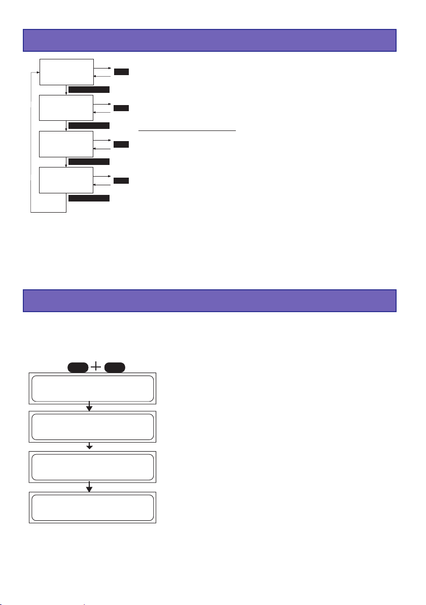
8. Scelta del gruppo del programma di carica
NiCd
Programma
AUTOMATICC
MODE (2 sec.)
NiMH
Programma
AUTOMATICC
MODE (2 sec.)
Lithium
Programma
MANUALE
MODE (2 sec.)
Pb
Programma
MANUALE
MODE (2 sec.)
Le possibilità di carica e scarica dell’ULTRAMAT 12 PLUS sono
suddivise in modo chiaro e logico in quattro gruppi di programmi.
MODE
Per i diversi tipi di accumulatori : Nichel-Cadmio, Nichel-Metal Idrato, Ioni di litio / Polimeri di litio / LiFePO
disposizione un proprio gruppo di programmi.
MODE
Un ulteriore gruppo di programmi comprende le possibilità di im-
(LiFe) e Piombo c’è a
4
postazione individuali del caricabatterie.
Cambio del programma:
Finché l’apparecchio si trova in un gruppo di programmi di cari-
MODE
ca / scarica,non è possibile passare da un programma di carica al successivo.
Per passare da un gruppo di programmi al successivo, bisogna
MODE
premere il tasto MODE per ca. due secondi. Per passare da un
programma al successivo all’interno del gruppo, esercitare un
breve pressione sul tasto MODE.
9. Prima di cominciare
Dopo aver collegato l’ingresso 12V DC ad una batteria per auto o ad un alimentatore 11 … 15V
DC di almeno 5 A, premete contemporaneamente i tasti INC e DEC per accedere alla scelta
della lingua. Altrimenti viene visualizzata la routine di informazioni sulle principali impostazioni
utente dell’apparecchio. Sul display appaiono in sequenza le seguenti indicazioni:
DECINC
________________
LANGUAGE SELECT
GERMAN
________________
ENTER
________________
Graupner V1.00
U12 PLUS POCKE T
________________
3 sec.
________________
Sicherheitstimer
ein
________________
3 sec.
________________Summer
ein
________________
74
Mentre provvedete sull’apparecchio la tensione
d’ingresso, premete i tasti INC e DEC per accedere alla
scelta della lingua. Premete i tasti INC o DEC per
scegliere la lingua INGLESE, TEDESCA o FRANCESE.
Uscite da questa scelta con il tasto ENTER.
L’ULTRAMAT 12 PLUS si presenta con il suo nome.
Il Timer di sicurezza è impostato , per gli accumulatori al
NiCd/NiMH e al Litio a 10...300 min. o Funzione on (ein =
aperto) o off (aus = spento), mentre per gli accu-mulatori
al piombo è disattivato.
Funzione on (ein = aperto) o off (aus = spento) o
10...300min con une breve pressione il tasti DEC o INC.
Funzione cicalino on (ein = aperto) o off (aus = spento) o
3...10s con une breve pressione il tasti DEC o INC.
Il caricabatterie è pronto per l’impiego.
Page 75

10. Avvio dei processi di carica / scarica
3 sec.
________________LiPo-Manuell
L:2.5A 2000mAh
________________
START
2
sec.
Per la carica, la scarica e la formattazione scegliete il
programma desiderato come descritto in seguito e
impostate i valori adatti.
Informazione equilibratore collegato Equilibratore non
collegato.
Collegate, se presente, il connettore per l’equilibratura
dell’accumulatore all’ingresso equilibratore (Input
Balancer).
Fate attenzione ad osservare la corretta polarità.
Da destra a sinistra: (Pin 1 (GND): Massa = Accu. - ,
Pin 2 (1): + Cella 1, Pin 3 (2): + Cella 2, Pin 4 (3): + Cella 3,
Pin 5 (4): + Cella 4, Pin 6 (5): + Cella 5, Pin 7 (6): + Cella 6)
Collegate successivamente, mediante l’impiego di un cavo
per la ricarica ed osservando la corretta polarità, il
connettore a 2 poli dell’accumulatore all’uscita del
caricabatterie - BATTERY +.
Se tenete premuto il tasto START per ca. 2 sec., vi verrà
indicato se l’equilibratore risulta essere collegato o meno.
Con l’equilibratore collegato è possibile visualizzare le
tensioni delle singole celle, 16..
________________**INFORMATION***
BALANCER ANG.
________________
2
sec.
________________VERMESSE AKKU
BITTE WARTEN...
________________
!Attenzione ! Dovete
assolutamente
impostare il numero
di celle corretto e
verificare il tipo di
accumulatore, onde
evitare che
l’accumulatore
possa esplodere ed
incendiarsi!
2
sec.
________________Man. 23:40 00863
LP+2.50A 14.017V
________________
________________**INFORMATION***
BALANCER N. ANG.
________________
2
sec.
________________VERMESSE AKKU
BITTE WARTEN...
________________
2
sec.
________________
**LiPo Zellen**
3 Zellen(13.73V)
________________
+
INC
DEC
START
Mediante un’ulteriore breve pressione sul tasto START
potete interrompere il processo di ricarica in qualsiasi
momento.
Nota: Se il processo di ricarica viene interrotto
tramite il tasto START, tutti i parametri sul display
vengono cancellati in maniera irrevocabile.
Nel caso di accumulatori tipo Litio, in
assenza di una connessione per
l’equilibratura, verrà eseguito il
rilevamento del numero di celle.
Quest’ultimo dovrà essere confermato
mediante pressione del tasto START.
-
Se premete il tasto START ancora
una volta, l’accumulatore collegato
verrà caricato oppure scaricato.
75
Page 76

11. Programmi NiCd
NiCd
Programma
AUTOMATICC
MODE MODE MODE MODE MODE
NiCd
Programma
MANUALE
NiCd
Programma
di scarica
NiCd
Programma
fermattazione
MODE
NiCd
Progr. di scarica
con equilibratura
NiCd
∆ ∆
∆
Delta-peak
∆ ∆
Tens.riferim
Programmi semplici da usare per la carica degli accumulatori NiCd solitamente usati nel modellismo. Quando il programma di carica / scarica è concluso, sul display appare, fino allo scollegamento dell’accumulatore, alternativamente con la scritta „ENDE“ (fine), il tempo di carica, gli ultimi valori della corrente di carica / scarica, la capacità e la tensione dell’accumulatore. Questi dati
danno, in questo caso, indicazioni preziose ed esaurienti sull’andamento della carica, sulla capacità dell’accumulatore NiCd collegato o su errori verificatisi.
NiCd-Programma automatico
________________NiCd-Automatik
L:2.5A begrenzt
________________
+
-
DECINC
In questo programma il caricabatterie riconosce il tipo di
accumulatore collegato e adegua la corrente di carica
corretta, in modo da evitare un sovraccarico dell’accumulatore. La corrente di carica massima
può essere impostata con i tasti INC / DEC prima di collegare l’accumulatore da 0.1 a 5.0 A senza limitazioni.
Il processo di carica termina in accordo con i valori impostati per la tensione di spegnimento del delta peak.
NiCd-Programma manuale
________________NiCd-Manuell
L:2.5A
________________
+
-
DECINC
Con questo programma potete caricare il vostro accumulatore con la corrente impostata. La corrente massima
può essere impostata prima di collegare l’accumulatore
con i tasti INC / DEC da 0.1 a 5.0 A.
Il processo di carica termina in accordo con i valori impostati per la tensione di spegnimento del delta peak.
________________NiCd-Entladen
1.00A 4.8V
________________
+
-
DECINC
+
INC
ENTER
76
NiCd-Programma di scarica
Questo programma serve per es. per determinare la capacità residua o per scaricare ad un determinato livello
l’accumulatore di una trasmittente, di una ricevente o di
alimentazione di un motore.
-
DEC
Con questo programma viene effettuata la scarica con
una corrente di scarica impostata (0.1 … 1.0 A, a sinistra
sul display) fino alla tensione finale di scarica (0.1 … 16.8
V , a destra sul display). Come tensione finale di scarica
dev’essere selezionato un valore tra 0.9 e 1.1 V per cella,
per non scaricare oltre l’accumulatore ed evitare
un’eventuale inversione di polarità .
Page 77

NiCd-Programma di formattazione
ENTER
INC
oder
DEC
________________NiCd Zykl. L>E 1
L:2.5A E:1.00A
________________
+
INC
-
DEC
ENTER
+
INC
NiCd Tensione equilibratore
________________NiCd Balancer-
spannung = 1.20V
________________
+
INC
START
________________**INFORMATION***
BALANCER ANG.
________________
2
sec.
INC
DEC
DEC
DEC
Questo programma serve per ottimizzare la capacità e la
formattazione di un accumulatore. In alto a destra sul
display impostate, con i tasti INC / DEC se il programma
di formattazione deve iniziare con la carica o la scarica.
Quindi impostate il numero di cicli da 1 a 5 (per es. impostando 3 cicli, l’accumulatore viene caricato e scaricato
tre volte).
Il programma scarica l’accumulatore con la corrente di
scarica impostata a destra sul display (0.1 … 1.0 A) per
poi ricaricarlo con la corrente impostata a sinistra sul
-
display (0.1 … 5.0 A).
L’interruzione della carica avviene in accordo con il valore
di tensione di riferimento del Delta peak.
La lettura dei valori è descritta nel capitolo „Indicazioni del
display“.
Questo programma serve per equilibrare le tensioni delle
singole celle di pacchi batterie con 2-6 celle.
Mediante il tasto INC oppure DEC potete impostare la
tensione limite di scarica dell’equilibratore tra 1.20...1.30V.
Prima della ricarica di un’accumulatore le tensioni delle
-
celle dovrebbero essere equilibrate, onde evitare la
sovraccarica di singole celle durante la ricarica.
Specialmente dopo un periodo di riposo prolungato,
un’accumulatore dovrebbe essere equilibrato.
Per fare ciò è necessario collegare il connettore
dell’equilibratore.
Inoltre tutte le celle devono presentare una tensione
superiore a quella impostata come soglia limite di scarica
per l’equilibratore.
2
sec.
Entl
________________BLC 28:30 01425
Entl
NC-3.00A 06.717V
________________
Per ottenere la capacità mass. di un’accumulatore le
singole celle dovrebbero essere scaricate fino a
raggiungere una tensione di 1.20V alcune ore, ma al
massimo 24h prima di una nuova ricarica. Con una
tensione inferiore a 1.20V le celle perdono capacità. Per
questo motivo un’accumulatore dovrebbe essere carico al
60% ca. prima di essere messo a riposo per un periodo
prolungato.
Il programma scarica il pacco batterie con 50mA...1,0A.
Celle con una tensione di cella superiore, vengono
scaricate con una corrente aggiuntiva di ca. 100mA
(equilibratura).
Se tutte le celle hanno raggiunto la soglia limite di scarica
dell’equilibratore (+0.01V), il processo di equilibratura
viene terminato.
77
Page 78
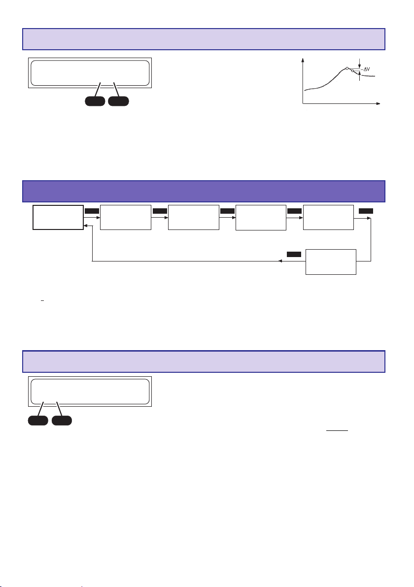
NiCd-Tensione di riferimento (-
∆∆
∆ Peak)
∆∆
________________NiCd Delta-Peak-
Volt =10mV/Zelle
________________
+
-
DECINC
Tensiore delle celle
Tempo di carica
Lo spegnimento automatico del processo di carica (riconoscimento di accumulatore completamente carico) funziona secondo il principio del delta peak, già provato milioni di volte e noto anche come delta-U o delta-V. In questo procedimento viene valutata la tensione massima della
curva di carica, che indica con molta precisione la massima carica immagazzinata.
Onde evitare di sovraccaricare l’accumulatore vi consigliamo di iniziare con una tensione di
spegnimento Delta-Peak di 10mV.
12. Programmi NiMH
NiMH
Programma
AUTOMATICC
MODE MODE MODE MODE MODE
NiMH
Programma
MANUALE
NiMH
Programma
di scarica
NiMH
Programma
fermattazione
MODE
NiMH
Progr. di scarica
con equilibratura
NiCd
∆ ∆
∆
Delta-peak
∆ ∆
Tens.riferim
Programmi semplici da usare per la carica degli accumulatori NiMH solitamente usati nel modellismo. Quando il programma di carica / scarica è concluso, sul display appare, fino allo scollegamento dell’accumulatore, alternativamente con la scritta „ENDE“ (fine), il tempo di carica, gli ultimi valori
della corrente di carica / scarica, la capacità e la tensione dell’accumulatore. Questi dati danno, in
questo caso, indicazioni preziose ed esaurienti sull’andamento della carica, sulla capacità dell’ accumulatore NiMH collegato o su errori verificatisi.
NiMH-Programma automatico
________________ NiMH-Automatik
L:2.5A begrenzt
________________
+
INC
-
DEC
In questo programma il caricabatterie riconosce il tipo
di accumulatore collegato e adegua la corrente di carica adatta, in modo da evitare una sovraccarica all’ accumulatore.
La corrente di carica può essere impostata con i tasti
INC / DEC da 0.1 A a 5.0 A senza limitazioni, prima di
collegare l’accumulatore.
Osservate le indicazioni del produttore dell’accumulatore!
Evitate assolutamente di ricaricare gli accumulatori con più
di 2C!
Es.: NiMH 6N-4200, corrente di carica mass. 8,4A, corrente
di carica veloce consigliata per accumulatori Graupner 4,2A.
La corrente di carica per gli accumulatori delle trasmittenti
deve essere limitata a 2A mass.!
78
Il processo di carica termina in accordo con i valori
impostati per la tensione di spegnimento del delta peak.
Page 79
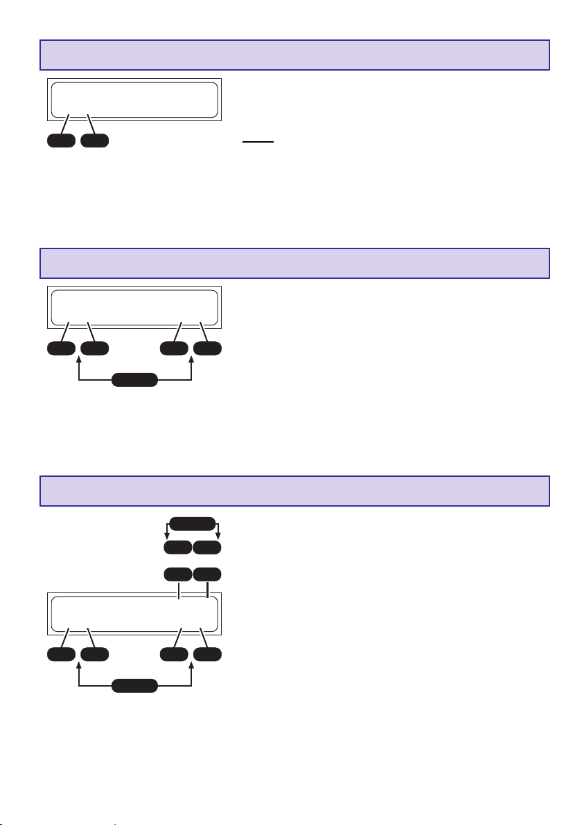
NiMH-Programma manuale
________________NiMH-Manuell
L:2.5A
________________
+
-
DECINC
NiMH-Programma di scarica
________________NiMH-Entladen
1.00A 4.8V
________________
+
-
DECINC
ENTER
+
Con questo programma l’accumulatore viene
caricato con la corrente di carica impostata.
La corrente di carica massima può essere impostata con i tasti INC / DEC da 0.1 A a 5.0 A
prima di collegare l’accumulatore.
Il processo di carica termina in accordo con i valori
impostati per la tensione di spegnimento del delta
peak.
Questo programma è utile per es. per determinare la capacità residua oppure per la scarica dell’accumulatore di una
trasmittente, di una ricevente o di alimentazione di un motore. Con questo programma viene effettuata la scarica con
-
una corrente di scarica impostata (0.10 … 1.0 A, a sinistra
DECINC
sul display) fino alla tensione finale di scarica (0.1 … 16.8 V
, a destra sul display).
Come tensione finale di scarica dev’essere selezionato un
valore tra 1.0 e 1.2 V per cella, per non scaricare oltre
l’accumulatore ed evitare un’eventuale inversione di polarità.
NiMH-Programma di formattazione
ENTER
INC
oder
DEC
________________NiMH Zykl. L>E 1
L:2.5A E:1.00A
________________
+
INC
-
DEC
ENTER
+
INC
Questo programma serve per ottimizzare la capacità e la
formattazione di un accumulatore. In alto a destra sul display impostate, con i tasti INC / DEC se il programma di for-
INC
mattazione deve iniziare con la carica o la scarica. Quindi
impostate il numero di cicli da 1 a 5 (per es. impostando 3
DEC
cicli, l’accumulatore viene caricato e scaricato tre volte).
Il programma scarica l’accumulatore con la corrente di scarica impostata a destra sul display (0.1 … 1.0 A) per poi ricaricarlo con la corrente impostata a sinistra sul display (0.1
… 5.0 A).
-
L’interruzione della carica avviene in accordo con il valore di
DEC
tensione di riferimento del Delta peak.
La lettura dei valori è descritta nel capitolo „Indicazioni del
display“.
79
Page 80
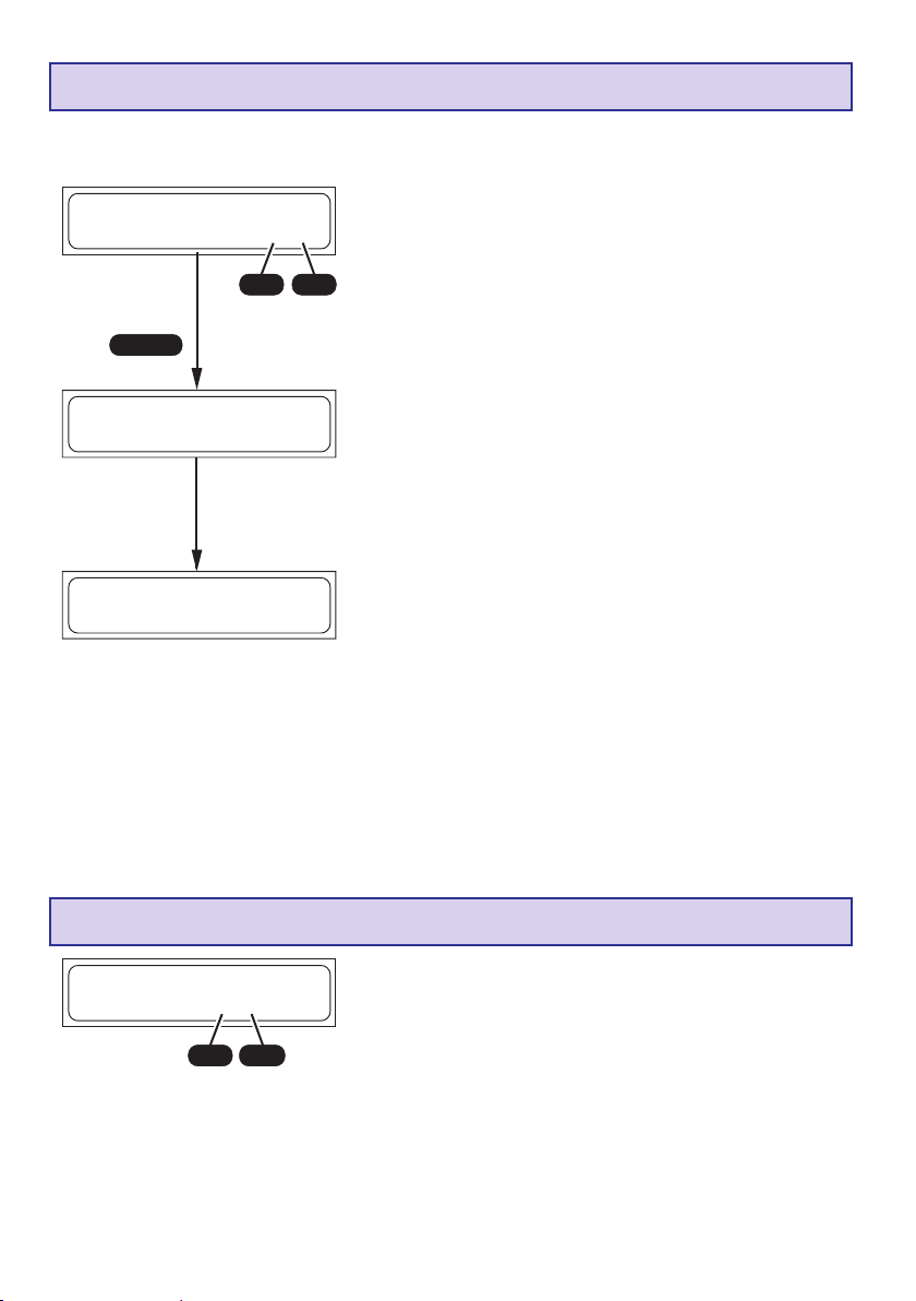
NiMH Tensione equilibratore
________________NiMH Balancer-
spannung = 1.20V
________________
+
INC
DEC
START
2
sec.
Questo programma serve per equilibrare le tensioni delle
singole celle di pacchi batterie con 2-6 celle.
Mediante il tasto INC oppure DEC potete impostare la
tensione limite di scarica dell’equilibratore tra 1.20...1.30V.
Prima della ricarica di un’accumulatore le tensioni delle
celle dovrebbero essere equilibrate, onde evitare la
-
sovraccarica di singole celle durante la ricarica.
Specialmente dopo un periodo di riposo prolungato,
un’accumulatore dovrebbe essere equilibrato.
Per fare ciò è necessario collegare il connettore
dell’equilibratore.
________________**INFORMATION***
BALANCER ANG.
________________
2
sec.
Entl
________________BLC 28:30 01425
Entl
NM-3.00A 06.717V
________________
Inoltre tutte le celle devono presentare una tensione
superiore a quella impostata come soglia limite di scarica
per l’equilibratore.
Per ottenere la capacità mass. di un’accumulatore le
singole celle dovrebbero essere scaricate fino a
raggiungere una tensione di 1.20V alcune ore, ma al
massimo 24h prima di una nuova ricarica. Con una
tensione inferiore a 1.20V le celle perdono capacità. Per
questo motivo un’accumulatore dovrebbe essere carico al
60% ca. prima di essere messo a riposo per un periodo
prolungato.
Il programma scarica il pacco batterie con 50mA...1,00A.
Celle con una tensione di cella superiore, vengono
scaricate con una corrente aggiuntiva di ca. 100mA
(equilibratura).
Se tutte le celle hanno raggiunto la soglia limite di scarica
dell’equilibratore (+0.01V), il processo di equilibratura
viene terminato.
NiMH-Tensione di riferimento del Delta-Peak (-
________________NiMH Delta-Peak-
Volt =10mV/Zelle
________________
+
-
DECINC
La tensione di riferimento (in mV per cella!) dello spegnimento automatico per gli accumulatori NiMH può essere impostata. Gli accumulatori NiMH tuttavia hanno una caduta di tensione inferiore agli accumulatori NiCd. Si sono rivelati accettabili valori di impostazione della tensione di 5 … 25 mV/cella.
Tensioni superiori provocano rapidamente una sovraccarica
dell’accumulatore, tensioni inferiori provocano spesso un’
interruzione anticipata.
Il valore più adatto al vostro accumulatore dev’essere trovato con varie prove di carica.
Onde evitare di sovraccaricare l’accumulatore vi
consigliamo di iniziare con una tensione di spegnimento
Delta-Peak di 5mV.
∆∆
∆ Peak)
∆∆
80
Page 81

13. Programmi Litio
Programmi sono adatti solo per la carica e la scarica di accumulatori agli di LiFePO4 (LiFe) con
una tensione di 3,3 V/cella ed Ioni di litio con una tensione di 3,6 V/cella ed ai Polimeri di litio ed al
Litio-Biossido di Manganese con una tensione nominale di 3,7 V/cella.
Gli accumulatori al litio si distinguono dagli altri tipi di accumulatori soprattutto per la loro
notevolmente maggiore capacità. Questo importante vantaggio tuttavia richiede un diverso
sistema di trattamento sia per quanto concerne la carica e la scarica, sia per ottenere un
funzionamento privo di pericoli.
Le seguenti prescrizioni fondamentali devono essere scrupolosamente osservate. Ulteriori
indicazioni ed avvertenze sulla sicurezza sono riportate nelle istruzioni tecniche del costruttore.
In linea di principio gli accumulatori al litio possono essere caricati SOLO con
speciali caricabatterie che siano impostati (tensione di fine carica, capacità) per
ciascun tipo di accumulatore. Il processo di carica avviene in modo diverso
dagli
accumulatori al NiCd o NiMH, mediante il cosiddetto metodo a corrente costante / tensione
costante. La corrente richiesta per la carica dipende dalla capacità e viene impostata automaticamente dal caricabatterie.Gli accumulatori al litio solitamente vengono caricati con una corrente
di carica 1 C (corrente di carica 1 C = corrente di carica relativa alla capacità. Esempio: per una
capacità di 1500 mA, la corrispondente corrente di carica = 1500 mA = 1.5 A). Perciò sul caricabatterie viene impostata la capacità dell’accumulatore, invece che la corrente di carica. Quando
viene raggiunta la tensione finale specifica per ciascun tipo di accumulatore, la corrente di carica
viene automaticamente ridottaper evitare un superamento della tensione finale di carica. Se le
istruzioni fornite dal costruttore dell’accumulatore indicano una corrente di carica inferiore a 1C,
allora deve essere ridotta, in modo corrispondente, anche la capacità.
Per una carica ottimale, una maggiore vita utile ed una maggiore sicurezza in fase di
ricarica raccomandiamo assolutamente di collegare il connettore dell’equilibratore alle
chargeur durante i processi di ricarica/scarica.
Voltaggio
Corrente
Tempo di carica
Problemi con il trattamento degli accumulatori:
Gli accumulatori al litio costituiscono un grosso pericolo in caso di sovraccarica, che può provocare sviluppo di gas, surriscaldamento e persino un’esplosione. Se la tensione finale di scarica
di 3,6 V /cella (LiFe) o di 4,1 V/cella (Ioni di litio) o di 4,2 V/cella (Polimeri di litio/LiMn) viene superata dell’1%, allora inizia una trasformazione degli ioni di litio in litio metallico. Questo, in unione
con l’acqua dell’elettrolita, reagisce violentemente e provoca l’esplosione della cella. Inoltre la
tensione finale di carica non dev’essere superata, poiché in tal caso diminuisce la capacità delle
celle agli ioni di litio. Una tensione di 0.1 V sotto la soglia significa già una perdita di circa il 7% di
capacità. Scariche profonde degli accumulatori al litio provocano una rapida perdita di capacità.
Questo fenomeno non è reversibile, perciò dev’essere in ogni caso evitato di scaricare
l’accumulatore sotto i 2,5 V/cella.
Attenzione: l’impostazione del tipo di accumulatore, della sua capacità e del numero di
celle deve concordare sempre con l’accumulatore da caricare e non deve mai differire,
pena il pericolo di esplosione! Non deve essere mai collegato un accumulatore che abbia un dispositivo di carica integrato!
Caricate i vostri accumulatori solo su superfici ignifughe.
Lithium
Programma
MANUALE
Lithium
MODE MODE
Programma
di scarica
Lithium
Stoccaggio
accumulatore
MODE
Lithium
Sccitra tipo
accumulatore
MODE
81
Page 82

Litio-Programma manuale
________________LiPo-Manuell
L:4.0 A 4000mAh
________________
+
INC
Durante la ricarica per motivi di sicurezza il collegamento del connettore
dell’equilibratore è assolutamente raccomandato!
Ora collegate l’accumulatore al caricabatterie e avviate il processo di carica. La corrente di carica inizia lentamente a salire da 0.00 A al valore limite impostato. Non meravigliatevi se la corrente di carica che avete impostato non viene raggiunta, poiché il programma di carica controlla
in continuazione la tensione dell’accumulatore ed evita un suo gonfiamento, mantenendo uguale
la tensione delle singole celle di un pacco. La diminuzione automatica della corrente di carica
viene indicata sul display con la scritta „ENDE“ (fine), alternandola con l’indicazione della corrente di carica ridotta.
DEC
-
ENTER
+
INC
-
DEC
Mediante questo programma l’accumulatore viene
ricaricato con la corrente di carica impostata.
Prima di collegare l’accumulatore da ricaricare è
necessario impostare la corrente di carica (0,1...5,0A, a
sinistra nel display) tramite i tasti INC / DEC. Premete
successivamente il tasto ENTER ed utilizzate i tasti INC /
DEC per impostare la capacità dell’accumulatore (50 ...
9900mAh, a destra nel display). Un superamento del 10%
della capacità impostata comporta l’interruzione del
processo di ricarica per motivi di sicurezza.
Litio-Programma di scarica
________________LiPo-Entladen
1.00A 2.5V/Zelle
________________
+
INC
-
DEC
ENTER
+
DECINC
Questo programma serve per es. per determinare la capacità
residua di un accumulatore non ancora scarico. Con questo
programma la scarica viene effettuata con la corrente di
scarica impostata (0.10…1.0 A, a sinistra sul display) fino al
-
raggiungimento della tensione finale di scarica impostata
(2.5…3.7 V per cella, a destra sul display). La tensione
finale di scarica di 2.5 V per cella non può essere superata,
altrimenti l’accumulatore può danneggiarsi.
Lithium-Programma stoccaggio
LiPo Lagerprog.
________________
________________
________________<2.0A
________________
+
INC
-
DEC
82
3.80V/Z
+
ENTER
Il presente programma serve a caricare o scaricare gli
accumulatori in modo da garantire lo stato di carica migliore
per lo stoccaggio.
Con questo programma l’accumulatore viene portato alla
tensione di stoccaggio impostata mediante carica o scarica.
In tal modo l’accumulatore può essere stoccato per molto
tempo.
Tensioni di stoccaggio ottimali:
-
DECINC
LiPo: 3,8...3,9V/cella
LiIo: 3,7...3,8V/cella
LiFe: 3,3...3,4V/cella
Page 83

Litio-Numero di celle
________________
**LiPo Zellen**
2 Zellen( 7.73V)
________________
+
INC
Attenzione ! Impostate esattamente
il numero di celle, altrimenti
I‘accumulatore potrebbe
esplodere ed incendiarsi!
-
DEC
Quando l’accumulatore viene collegato al caricabatterie e
viene premuto il tasto START per ca. 2 sec., sul display
appare l’indicazione con il numero di celle, che da 1 a 2
celle è riconosciuto e impostato automaticamente. Se il
pacco batterie contiene più di due celle, dovete impostare
manualmente, con i tasti INC / DEC, il numero di celle,
poiché non è possibile il riconoscimento automatico di un
pacco batterie con un numero maggiore di due celle. Sulla
destra è indicato, per controllo, la tensione dell’accumulatore collegato. Con un’ulteriore pressione del tasto
START, inizia il processo di carica.
Litio-Programma di scelta del tipo
________________
Lithium Typ
LiPo 4.20/c
________________
+
INC
L’impostazione del tipo di accumulatore (LiPo o LiIo o LiFe) determina la tensione di spegnimento.
Se un accumulatore al litio viene caricato solo per i 2/3 dell’aspettativa, probabilmente avete
sbagliato, in questa sede, l’impostazione del tipo di accumulatore.
Attenzione: Se avete impostato un valore errato, l’accu-mulatore, in conseguenza di ciò , può
venir danneggiato irreparabilmente o addirittura può esplodere!
La tensione finale di carica può essere impostata in intervalli di 0,01V. La
tensione finale di carica massima ammessa per LiPo è pari a 4,2V, per LiIo 4,1V e per LiFe 3,6V.
Per immagazzinare gli accumulatori, la tensione finale di carica andrebbe impostata più bassa di
circa 0,4V.
-
DEC
Questo è il più importante programma di impostazione
per i pacchi batteria al litio. In questo programma viene
impostato il tipo di accumulatore. Questa impostazione va
fatta con molta attenzione e verificata, poiché da essa il
caricabatterie ricava tutti gli altri parametri per la carica.
Durante la ricarica i tipi di accumulatori vengono indicati nella seguente maniera:
LiPo (LiMn) = LP
LiIo = LI
LiFe = LF
14. Programmi Pb
Pb
Programma
MANUALE
Questi programmi servono per la carica e la scarica di un accumulatore al piombo, con acido
solforico o gel, di 2, 4, 6 o 12 V precisi (1, 2, 3, 6, celle).
Attenzione: Batterie al piombo con tensioni nominali diverse non vengono riconosciuti dal
caricabatterie e quindi non devono essere collegati. Gli accumulatori al piombo si comportano in
modo completamente diverso da quelli al NiCd o NiMH. Con riferimento alla loro capacità, gli
accumulatori al piombo forniscono correnti relativamente inferiori a quelle degli accumulatori
NiCd o NiMH. Ciò si riflette soprattutto sulla loro ricarica, per la quale i produttori di batterie
indicano per lo più un tempo da 14 a 16 ore per raggiungere la capacità nominale con una
corrente normale di ricarica. Per corrente normale di carica si intende 1/10 del valore nominale di
capacità dell’accumulatore. Esempio: se la capacità dell’accumulatore è di 12 Ah, la corrente
normale di ricarica è di 1,2 Ah. La carica completa viene riconosciuta dal caricabatterie (a
differenza dagli accumulatori al NiCd o NiMH) in base alla tensione dell’accumulatore.
MODE MODE
Pb
Programma
di scarica
83
Page 84
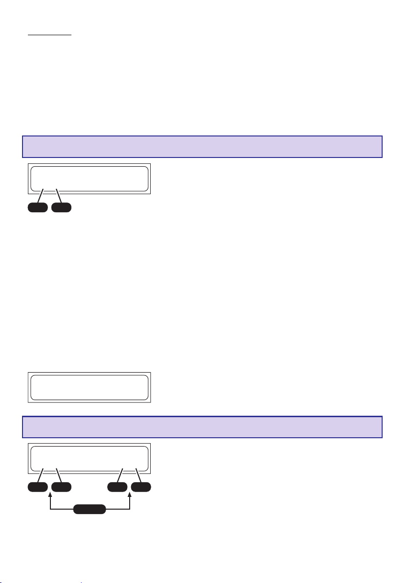
Attenzione: le batterie al piombo non possono essere sottoposte ad un processo di
carica rapida! Scegliete perciò sempre la corrente di ricarica indicata dal produttore della
batteria. Fate attenzione anche che una manutenzione errata di un accumulatore al piombo
(sovraccarica, molte scariche al 100% e soprattutto scariche molto profonde) incide molto
negativamente sulla sua capacità nominale ( cioè sulla durata). Anche il valore della corrente di
carica / scarica determina la capacità assimilabile dell’accumulatore, nel senso che tanto
maggiore è la corrente, tanto minore sarà la capacità finale dell’accumulatore. I valori di ritardo
dello spegnimento e del Timer di sicurezza impostati nelle impostazioni utente non hanno alcun
valore nei programmi di carica degli accumulatori al piombo.
Pb-Programma-manuale
________________Pb-Manuell
L:2.5A
________________
+
Se il produttore dell’accumulatore indica una corrente di carica inferiore, è necessario ridurre
anche la corrente di carica, poiché il caricabatterie, nel tentativo di fornire una carica maggiore
all’accumulatore, potrebbe impostare una corrente di carica superiore. Dopo che l’accumulatore
è stato collegato ed è iniziato il processo di carica, la corrente di carica comincia a salire lentamente da 0.00 A fino al limite impostato. Durante la carica, l’accumulatore viene costantemente
monitorato e la corrente di carica adattata alla nuova situazione. Il programma di carica, in base
alla misura della tensione, determina automaticamente il numero di celle. Non meravigliatevi tuttavia, se la corrente di carica che avete impostato non viene raggiunta, poiché il programma di
carica controlla continuamente la tensione della batteria ed evita così la formazione di gas
nell’accumulatore. Ora l’accumulatore viene caricato fino al raggiungimento di circa 2.3 V … 2.35
V per cella con la massima corrente di carica possibile. Quindi viene eseguito un processo più
delicato per effettuare la carica completa. La corrente di carica viene ulteriormente ridotta per
ottenere la massima carica possibile dell’accumulatore. La fine del processo di carica avviene
automaticamente al raggiungimento di una tensione di circa 2.45 V fino a 2.5 V per cella.
Con l’adattamento automatico della corrente, è possibile ottenere una carica più rapida con un
tempo notevolmente inferiore alle 14 - 16 ore.
-
DECINC
________________
CHG 367 :0 9 04448
ENDE
Pb 0mA 2.147V
________________
Con questo programma si può impostare, prima di
collegare l’accumulatore, con i tasti INC / DEC, la
massima corrente di carica ammessa (corrente di carica
massima).
Questa impostazione fissa solamente il limite superiore,
che il caricabatterie può fornire all’accumulatore.
Quando il processo di carica è completato, viene emesso
un segnale acustico per un determinato intervallo di
tempo. Contemporaneamente sul display lampeggia la
scritta „ENDE“ (fine).
Pb-Programma di scarica
________________Pb-Entladen
1.00A 12.0V
________________
+
INC
-
DEC
ENTER
+
DECINC
Questo programma serve per es. per determinare la
capacità residua di un accumulatore di alimentazione di un
motore.
Con questo programma la scarica viene effettuata con la
-
corrente di scarica impostata (0.1…1.0 A, a sinistra sul
display) fino al raggiungimento della tensione finale di
scarica impostata (1.7…12.0 V a destra sul display).
Per una misura della capacità significativa, la corrente di
scarica dovrebbe rimanere sotto 1 C (capacità dell’accumulatore = 2 Ah à C = 2 A) e come tensione di fine scarica
dev’essere scelto un valore di circa 1.7 V per cella.
84
Page 85

Programma
15. Indicazioni del display
Tempo di carica/scarica
(min.: sec.)
Man. 12:56 00321
________________
NC+4.50A 11,985V
________________
Capacità (mAh)
Tipo accumulatore
I dati essenziali relativi alla carica e scarica vengono visualizzati chiaramente sulle due righe del
display a cristalli liquidi e sono mantenuti fino allo scollegamento dell’accumulatore. Quando viene
collegato un altro accumulatore i valori precedenti non sono più richiamabili.
Corrente di carica/scarica
Tensione accumulatore
16. Indicazioni di controllo sul display
Il caricabatterie è dotato di un grande numero di protezioni e di controlli per monitorare le singole
funzioni ed i circuiti elettronici. Un superamento dei valori limite provoca in certi casi l’interruzione
del processo di carica (per es. in caso di sovratensione, temperatura troppo alta o batteria
dell’auto scarica).
Questi fattori provocano una segnalazione, sul display a cristalli liquidi, della causa dell’errore ed
una segnalazione acustica del cicalino.
Configurazione iniziale
Dopo la pressione del tasto START per ca. 2 sec., prima
________________VERMESSE AKKU
BITTE WARTEN...
________________
che venga avviato il processo di carica, l’accumulatore
viene configurato e per 1 – 2 sec. sul display appare
questa indicazione.
Indicazione di carica completata
ENDE
________________
CHG 48:32 03363
NC 200mA 9.773V
________________
Quando un programma di carica / scarica ha completato il
suo processo, sul display appare, alternativamente alla
descrizione del programma, la scritta „ENDE“ (fine). Contemporaneamente viene emesso un clic del tasto o una
segnalazione del cicalino in accordo.
Indicazione connettore equilibratore collegato
________________BLC 28:30 02850
Man.
LP+6.00A 14.717V
________________
Se il connettore per l’equilibratore dell’accumulatore risulta
essere collegato al caricabatterie e l’equilibratore è attivo,
nel display appare BLC in alto a sinistra. Questa
indicazione si alterna con la denominazione del
programma.
85
Page 86

Indicazione della tensione d‘ingresso e la resistenza interna dell‘accumulatore
L’attuale tensione d’ingresso e la resistenza interna
DECINC
________________Eingangsspannung
________________
13,62V
Innenwid. Batt.
________________
25m
L’indicazione della resistenza interna permette di controllare la qualità dell’accumulatore. La
resistenza interna viene misurata, durante il processo di carica/scarica, dopo 1...10 minuti e alla
fine del processo.
Con la pressione di un qualsiasi tasto si ritorna al menù.
dell’accumulatore può essere richiamata, in qualsiasi
momento, con la contemporanea pressione dei tasti INC e
DEC. Premendo il tasto INC o DEC passate all’indicazione
della resistenza interna, delle tensioni delle singole celle
oppure della tensione d’ingresso.
Indicazione delle tensioni delle singole celle
DECINC
________________Eingangsspannung
________________
13,62V
Innenwid. Batt.
________________
25m
]]]]]]]]
________________1.
]]]] 4.153V
]]]]]]]]
________________
]]]]]]]]
2.
________________3.
________________
4. 0.000V
________________5. 0.000V
________________
6. 0.000V
]]
]]]]
] 4.168V
]]]]]]]]
]]
]]]]]]
]]] 4.053V
]]]]]]
La tensione d’ingresso attuale e la resistenza interna
dell’accumulatore possono essere richiamate in qualsiasi
momento mediante la pressione contemporanea dei tasti
INC e DEC. Premendo il tasto INC o DEC passate
all’indicazione della resistenza interna, delle tensioni delle
singole celle oppure della tensione d’ingresso.
L’indicazione delle tensioni delle singole celle serve per la
verifica delle tensioni delle singole celle (1-6 celle).
86
Page 87

17. Segnalazioni di errore ed avvertenze
Il caricabatterie è dotato di un grande numero di protezioni e di controlli per monitorare le singole
funzioni ed i circuiti elettronici. Un superamento dei valori limite provoca in certi casi la riduzione
automatica delle impostazioni del caricabatterie (per es. della corrente di carica / scarica) o allo
spegnimento del processo di carica (per es. quando la batteria dell’auto è completamente scarica). La causa dell’errore viene visualizzata sul display a cristalli liquidi. La maggior parte delle
cause di errore sono autoesplicative, tuttavia quelle contenute nella lista che segue, possono
essere di aiuto per individuare gli errori. Le segnalazioni di avvertenza e acustiche possono essere cancellate con il tasto „ENTER“.
________________
*****FEHLER*****
Autobatt. leer
________________
Questa avvertenza viene segnalata quando la tensione
della batteria dell’auto si trova al di sotto del valore impostato nel menù „Spegnimento per tensione insufficiente“
nelle impostazioni utente (11.0 V ).
________________
*****FEHLER*****
Falschpolung
________________
________________
*****FEHLER*****
Unterbrechung
________________
________________
*****FEHLER*****
Ladezeit übersch
________________
________________
*****FEHLER*****
Spann. übersch.
________________
Questa segnalazione avverte che all’uscita del carica
batterie è stato collegato un accumulatore con i poli
invertiti.
Questa segnalazione appare quando si verifica, durante il
processo di carica / scarica, un’interruzione del collegamento tra l’accumulatore ed il caricabatterie. Se questa
segnalazione appare durante il funzionamento, ciò può
rivelare un falso contatto.
Avviso: Questa segnalazione di errore compare anche
quando voi interrompe la carica, per esempio scollegando
l’accumulatore.
Se il processo di carica continua fino alla scadenza
dell’intervallo fissato per il Timer di sicurezza, avviene
un’interruzione dei processi in corso.
Il Timer di sicurezza è impostato , per gli accumulatori al
NiCd/NiMH e al Litio a 180 min., mentre per gli accumulatori al piombo è disattivato. Queste impostazioni non
possono essere cambiate. Possibili cause: la corrente di
carica é troppo bassa e quindi l’accumulatore non è
carico, i cavi di collegamento sono troppo sottili o troppo
lunghi e perciò la corrente di carica non può salire sufficientemente, la capacità dell’accumulatore è troppo
grande.
Questa segnalazione indica una tensione troppo alta a
causa di un’errata impostazione del numero di celle per un
accumulatore al litio oppure un’impostazione di un accumulatore al piombo errata.
Questa segnalazione viene visualizzata anche per una
sovraccarica delle celle collegate.
________________
*****FEHLER*****
Spann. untersch.
________________
Questa segnalazione indica una tensione troppo bassa a
causa di un’errata impostazione del numero di celle per un
accumulatore al litio oppure un’impostazione di un accumulatore al piombo errata. La causa di questa segnalazione è che le celle, per un’errata impostazione, vengono
scaricate troppo profondamente.
87
Page 88

________________
*****FEHLER*****
Bal.Spg.übersch.
________________
Questo messaggio di errore appare quando il
caricabatterie rileva una tensione delle celle troppo
elevata in ingresso all’equilibratore.
Il messaggio di errore appare in presenza delle seguenti
tensioni:
LiPo > 4,3V, LiIo > 4,2V, LiFe > 3,9V, NiCd/NiMH > 2,0V
Inoltre l’indicazione di errore può apparire in caso di
sovraccarica delle celle collegate.
________________
*****FEHLER*****
Bal.Spg.untersch
________________
________________
*****FEHLER*****
BALANCER N. ANG
________________
Questo messaggio di errore appare quando il
caricabatterie rileva una tensione delle celle troppo bassa
in ingresso all’equilibratore.
Il messaggio di errore appare in presenza delle seguenti
tensioni:
LiPo < 2,75V, LiIo < 2,75V, LiFe < 2,0V, NiCd/NiMH < 0,1V
In questo caso è consigliabile effettuare una prima ricarica
dell’accumulatore senza collegare l’equilibratore e
limitando il processo di ricarica a pochi minuti (mass. 5
min.) ad esempio in modalità programma LiFe, che
ammette una tensione di 2V per cella,.
Attenzione: Singole celle potrebbero essere
danneggiate e di conseguenza il pacco batterie deve
essere ricaricato solamente sotto attenta
sorveglianza. Quando la tensione è di nuovo
sufficientemente alta, per motivi di sicurezza
l’accumulatore deve assolutamente essere ricaricato
con l’equilibratore collegato (pericolo di esplosione
ed incendio)!
Questo messaggio di errore appare quando si avvia il
programma di scarica con equilibratura per accumulatori
NiCd/NiMH senza avere collegato l’equilibratore.
.
Questo messaggio di errore appare anche quando
l’equilibratore viene scollegato durante un processo di
ricarica o scarica.
18. Interfaccia PC
Scaricate nel sito www.graupner.de sotto il punto „Produktsuche“ (Product search/ Ricerca prodotto):
6463 il software del corrispondente driver seriale USB CP210x_Drivers.exe per questo caricabatterie
e installate il driver.
Inserite il cavo USB nell’interfaccia PC del caricabatterie. Collegate il cavo USB ad una interfaccia
USB libera del vostro PC.
Un software per PC può essere scaricato dai siti www.graupner.de, www.gm-racing.de oppure
www.logview.info.
Con questo software potete visualizzare le curve, confrontarle ed eseguire altre operazioni.
88
Page 89

19. Pulizia e manutenzione
Il caricabatterie funziona senza alcuna necessità di manutenzione. Nel vostro interesse proteggetelo da polvere, sporcizia e umidità.
Per pulirlo, dopo averlo scollegato dalla batteria dell’auto, passate con delicatezza un panno asciutto (non usate detersivi!).
20. Indicazioni per il trattamento degli accumulatori
• La carica di una singola cella NiCd o NiMH o di un pacco batterie con 1…4 celle presenta un
serio problema di spegnimento automatico, poiché il picco di tensione non è molto sensibile e
non è garantito uno svolgimento corretto della funzione. Il funzionamento automatico non può
reagire correttamente. Eseguite perciò prove ripetute, controllando se la funzione di spegnimento automatico funziona correttamente con il vostro accumulatore.
• Le batterie calde sono più efficienti di quelle fredde. Non meravigliatevi perciò se in inverno le vostre
batterie hanno un rendimento minore.
• Sia la sovraccarica che la scarica profonda provocano un danno irreparabile alle celle riducendone
in modo duraturo l’efficienza e la capacità.
• Non mettete a riposo per un lungo tempo una batteria scarica, vuota o caricata solo parzialmente.
Prima di metterla a riposo, caricatela e di tanto in tanto controllate il suo stato di carica.
• Acquistate accumulatori di buona qualità, caricateli all’inizio con una corrente di carica piccola ed
aumentatela solo gradualmente.
• Caricate gli accumulatori solo poco prima del loro utilizzo, così il loro rendimento sarà migliore.
• Non effettuate saldature direttamente sugli accumulatori. Le alte temperature della saldatura
rovinano le guarnizioni e le valvole di sicurezza della cella, l’accumulatore perde elettrolita o si secca
e perde le sue potenziali prestazioni.
• La sovraccarica riduce la capacità dell’accumulatore. Quindi non caricate un accumulatore molto
caldo o già carico.
• Caricare e scaricare un accumulatore con correnti alte riduce le sue aspettative di durata. Non
superate perciò le indicazioni fornite dal costruttore.
• Gli accumulatori al piombo non sopportano forti correnti di carica. Non superate perciò le indicazioni
fornite dal costruttore.
• Proteggete l’accumulatore da vibrazioni e non sottoponetelo ad alcun carico meccanico.
• Durante il processo di carica e l’utilizzo di un accumulatore ci può essere emissione di idrogeno.
Mantenete gli ambienti quindi ben aerati.
• Non portate l’accumulatore a contatto con l’acqua, potrebbe esplodere.
• Non cortocircuitate mai i terminali di un accumulatore, potrebbe esplodere.
• Accumulatori a causa di un difetto possono esplodere oppure incendiarsi. Per questo motivo noi
consigliamo di ricaricare tutti gli accumulatori al Litio, oltre a quelli NiCd e NiMH all’interno di una
valigetta di sicurezza LiPo (Art.-Nr. 8370 oppure 8371).
• Non aprite le batterie, c’è il pericolo di corrosione.
• Gli accumulatori NiCd/NiMH vengono formattati meglio se prima si scaricano separatamente le
singole celle ed infine si carica l’intero pacco. La scarica si effettua con il caricabatterie (cella per
cella).
• Non meravigliatevi se il vostro pacco batterie si carica di meno in inverno che d’estate. Il rendimento
di una cella fredda é inferiore di quello di una calda.
• Avvertenza sulla regolamentazione delle batterie: Le batterie usate sono rifiuti speciali e non devono
essere gettati nel cassonetto delle immondizie, ma nei contenitori appositi per la raccolta
differenziata delle batterie.
89
Page 90

21. Caratteristiche tecniche
Accumulatore:
Corrente di carica / rendimento 100mA - 5,0A / max. 50W (Tensione d‘ ingresso 11...15V DC)
Corrente di scarica / rendimento 100 mA - 1 A / max. 5 W
Accumulatori Ni-Cd & Ni-MH:
Numero di celle 1 - 14 celle
Capacità da 0,1 Ah - 9,9 Ah
Accumulatori al litio:
Numero di celle 1-6 celle
Tensione delle celle 3,3 V (LiFe) / 3,6 V (LiIo) rispettiv. 3,7 V (LiPo/LiMn)
Capacttà da 0,1 Ah - 9,9Ah
PB-Akkus:
Numero di celle 1, 2, 3, 6
Tensione dell‘accumulatore 2, 4, 6, 12 V
Capacità da 1 Ah
Sonstiges:
Tensione di funzionamento DC 11,0 fino a 15 V DC (tensione d’ingresso DC)
Tensione di funzionamento AC 100~240V AC (tensione d’ingresso AC)
Batteria auto necessaria 12 V, min. 30 Ah
Alimentatore necessario 11-15V, min. 5 A stabilizzato
Assorbimento senza carico ca. 0,1 A
Bassa tensione di spegnimento ca. 11,0 V
Connessione equilibratore: 1...6 celle NiMH/NiCd/LiPo/LiIo/LiFe
Corrente di equilibratura mass. ca: NiMH/NiCd: 0,1A, LiPo/LiIo/LiFe: 0,3A
Peso ca. 210 g
dimensioni ca. 123 x 85 x 28 mm
Tutti I dati si riferiscono ad una tensione di batteria per auto di 12.7 V.
Tutti i valori dichiarati sono indicativi e possono variare secondo lo stato dell’accumulatore usato, la temperatura, ecc.
1) Un funzionamento corretto del caricabatterie collegato ad un alimentatore dipende da molti fattori, come per es. la forma d’onda, la
stabilità, ecc. Usate solo apparecchi consigliati da noi.
1)
Indicazioni sulla protezione dell’ambiente
Questo simbolo, stampato sul prodotto o indicato nelle istruzioni per l’uso o sulla
confezione, avvisa che questo prodotto, alla fine del suo utilizzo, non deve essere
gettato nel normale contenitore per l’immondizia, ma de v’essere portato ad un punto di raccolta
per il riciclaggio di materiali elettrici ed elettronici.
I materiali, ciascuno secondo le proprie caratteristiche, sono riutilizzabili. Con il riciclaggio di
materiali e di vecchie apparecchiature, potrete dare un importante contributo alla protezione
dell’ambiente.
Batterie ed accumulatori devono essere rimossi dalle apparecchiature ed eliminati presso un
centro di raccolta appositamente predisposto.
Dai modelli RC devono essere smontati ed smaltiti presso un centro di raccolta di rottami
elettronici tutti gli elementi elettronici come per esempio servocomandi, riceventi, regolatori.
Informatevi sulla dislocazione dei centri di raccolta differenziata della vostra zona.
90
Page 91

Konformitätserklärung / Conformity Declaration /
Déclaration de conformitè / Dichiarazione di conformità
EG-Konformitätserklärung
Für das folgend bezeichnete Erzeugnis
Ultramat 12 PLUS POCKET; Best.-Nr. 6463
wird hiermit bestätigt, dass es den wesentlichen
Schutzanforderungen entspricht, die in der Richtlinie des Rates zur Angleichung der Rechtsvorschriften der Mitgliedstaaten über die elektromagnetische Verträglichkeit (89/336/EWG) bzw. die
elektrische Sicherheit (73/23/EG) festgelegt sind.
Zur Beurteilung des Erzeugnisses hinsichtlich
elektromagnetischer Verträglichkeit wurden folgende Normen herangezogen:
EMV: EN 61000-6-1 / EN 61000-6-3
Diese Erklärung wird verantwortlich für den
Hersteller/Importeur
Graupner GmbH & Co. KG
Henriettenstr. 94-96
73230 Kirchheim/Teck
abgegeben durch
73230 Kirchheim/Teck, den 03.12.09
Hans Graupner
Geschäftsführer
EMV: EN 61000-6-1 / EN 61000-6-3
This declaration was produced by:
Graupner GmbH & Co. KG
Henriettenstr. 94-96
73230 Kirchheim/Teck
and is valid for the manufacturer / importer of
the product
73230 Kirchheim/Teck, Germany, on 03.12.09
Hans Graupner
Managing Director
Déclaration de conformité EG :
Pour le produits suivant
Ultramat 12 PLUS POCKET; Réf. N°6463
Nous confirmons que la compatibilité
électronique correspond aux directives 89/
336/EWG et LVD (73/23/EG).
Normes appliquées :
EMV: EN 61000-6-1 / EN 61000-6-3
EU Conformity Declaration
We hereby declare that the following product:
Ultramat 12 PLUS POCKET; Order-No. 6463
conforms with the essential protective
requirements as laid down in the directive for
harmonising the statutory directives of the
member states concerning electro-magnetic
interference (89/336/EWG) and LVD (73/23/EG).
This product has been tested for electro-magnetic
interference in accordance with the following
norms:
Cette déclaration est sous la responsabilité
du Fabricant/Importateur
Graupner GmbH & Co. KG
Henriettenstr. 94-96
73230 Kirchheim/Teck
Fait à
73230 Kirchheim/Teck, le 03.12.09
Hans Graupner
Le Directeur d’Entreprise
91
Page 92

Wir gewähren auf dieses Erzeugnis eine / This product is / Sur ce produit nous accordons une
Garantie von
warrantied for
garantie de
22
2
22
44
4
44
Monaten
month
mois
Die Fa. Graupner GmbH & Co. KG, Henriettenstraße 94-96.
73230 Kirchheim/Teck gewährt ab dem Kaufdatum auf
dieses Produkt eine Garantie von 24 Monaten.
Die Garantie gilt nur für die bereits beim Kauf des Produktes vorhandenen Material- oder Funktionsmängel. Schäden die auf Abnützung, Überlastung, falsches Zubehör
oder unsachgemäße Behandlung zurückzuführen sind, sind
von der Garantie ausgeschlossen.
Die gesetzlichen Rechte und Gewährleistungsansprüche
des Verbrauchers werden durch diese Garantie nicht berührt.
Bitte überprüfen Sie vor einer Reklamation oder Rücksendung das Produkt genau auf Mängel, da wir Ihnen bei
Mängelfreiheit die entstandenen Unkosten in Rechnung
stellen müssen.
Graupner GmbH & Co. KG, Henriettenstraße 94-96, 73230
Kirchheim/Teck, Germany guarantees this product for a
period of 24 months from date of purchase.
The guarantee applies only to such material or operational
defects witch are present at the time of purchase of the
product.
Damage due to wear, overloading, incompetent handling
or the use of incorrect accessories is not covered by the
guarantee.
The user´s legal rights and claims under garantee are not
affected by this guarantee.
Please check the product carefully for defects before you
are make a claim or send the item to us, since we are
obliged to make a charge for our cost if the product is
found to be free of faults.
La société Graupner GmbH & Co. KG, Henriettenstraße
94-96, 73230 Kirchheim/Teck, Allemagne, accorde sur ce
produit une garantie de 24 mois à partir de la date d´achat.
La garantie prend effet uniquement sur les vices de
fonctionnement et de matériel du produit acheté. Les
dommages dûs à de l´usure, à de la surcharge, à de
mauvais accessoires ou à d´une application inadaptée,
sont exclus de la garantie.
Cette garantie ne remet pas en cause les droits et
prétentions légaux du consommateur.
Avant toute réclamation et tout retour du prouit, veuillez
s.v.p. cotrôler et noter exactement les défauts ou vices du
produit, car tout autre frais relatif au produit vous sera
facturé.
Servicestellen / Service / Service après-vente
Graupner-Zentralservice
Graupner GmbH & Co. KG
Postfach 1242
D-73220 Kirchheim
Espana
FA - Sol S.A.
C. Avinyo 4
E 8240 Manresa
(+34) 93 87 34 23 4
EMail: fasol@olivet.com
Italia
GiMax s.n.c.
Via Manzoni, no. 8
I 25064 Gussago
(+39) 3 0 25 22 73 2
Schweiz
Graupner Service Schweiz
Wehntalerstrasse 37
CH 8181 Höri
(+41) 43 26 66 58 3
UK
GLIDERS
Brunel Drive
Newark, Nottinghamshire
NG24 2EG
(+44) 16 36 61 05 39
Belgie/Nederland
Jan van Mouwerik
Slot de Houvelaan 30
NL 3155 Maasland VT
(+31)10 59 13 59 4
Servicehotline
(+49)(01805) 472876
Montag - Freitag
930 -1130 und 1300 -1500 Uhr
France
Graupner Service France
Gérard Altmayer
86, rue ST. Antoine
F 57601 Forbach-Oeting
(+33) 3 87 85 62 12
Sverige
Baltechno Electronics
Box 5307
S 40227 Göteborg
(+46) 31 70 73 00 0
Luxembourg
Kit Flammang
129, route d’Arlon
8009 Strassen
(+35) 23 12 23 2
Ceská Republika/Slovenská
Republika
RC Servis Z. Hnizdil
Leteckà 666/22
CZ-16100 Praha 6 - Ruzynè
(+42) 2 33 31 30 95
Garantie-Urkunde
Warranty certificate / Certificat de garantie
ULTRAMAT 12 PLUS POCKET, #6463
Übergabedatum, Date of purchase/delivery, Date de remise
Name des Käufers, Owner´s name, Nom de l´acheteur
Strasse, Wohnort, Complete adress, Domicie et rue
Firmenstempel und Unterschrift des Einzelhändlers, Stamp and
signature of dealer, Cachet de la firme et signature du detailant
92
 Loading...