

Page 1
GRAUPNER GmbH & Co. KG D-73230 KIRCHHEIM/TECK GERMANY
Keine Haftung für Druckfehler. Technische Änderungen vorbehalten! Liability for printing errors excluded. We reserve the right to introduce modifications. Sous réserve de modifications! Nous ne sommes pas responsables d’éventuelles erreurs d’impression! #0059054 04/2008
1
Betriebsanleitung für das Modell THEODOR HEUSS, Best.-Nr.: 2013
Beschreibung des Originals (Text © by DGzRS, Bremen)
Es herrschte eine spürbar höhere Betriebsamkeit in der Bremer Innenstadt als an normalen Tagen. Es war
an einem Freitag, dem 12. Februar 1957. Viele Menschen bevölkerten den Hauptbahnhof der Hansestadt
zu früher Stunde als ein Sonderzug aus der damaligen Bundeshauptstadt Bonn einfuhr. Ihm entstieg Professor Theodor Heuss, Bundespräsident und Schirmherr des Rettungswerkes, um der feierlichen Taufe des
ersten Seenotkreuzers der DGzRS beizuwohnen.
In Begleitung von DGzRS-Vorsitzenden Hermann Helms sen. und Bremens Bürgermeister Wilhelm Kaisen
reiste das Staatsoberhaupt an Bord des Versuchs-Seenotkreuzers HERMANN APELT weserabwärts ins
niedersächsische Bardenfleth. Dicht gedrängt standen die Menschen am Flussufer und auf den Deichen.
Die Schulen hatten den Kindern unterrichtsfrei gegeben.
Ziel der kurzen Reise auf der Weser war das Gelände der Schweers-Werft, heute Lürssen-Bardenfleth. In
der festlich geschmückten Schiffbauhalle formulierte Hanne Heuss, die Schwiegertochter des Bundespräsidenten, den Taufspruch:
Fahre, Schiff,
Du tapf'rer Retter
Durch der Stürme böses Wetter,
zu dem Bruder, der in Not
bis Dein Helfen sich ihm bot daß als großes Vorbild bliebe:
Tapferkeit und Menschenliebe
Mit dem Zerschellen der obligatorischen Sektflasche am Schiffsrumpf taufte sie den neuen modernen Seenotkreuzer auf den Namen THEODOR HEUSS. Das Tochterboot erhielt den Namen TEDJE.
Der Seenotkreuzer gilt als Meilenstein im Spezialschiffbau. Er war der erste schnelle Seenotkreuzer mit
einem funktionstüchtigen Tochterboot. Die Definition "schnell" bedeutete dabei das Erreichen einer Dauergeschwindigkeit von 20 Knoten. Die THEODOR HEUSS war damit 1957 annähernd doppelt so schnell als
alle übrigen Allwetter-Seenotfahrzeuge in Deutschland und Europa.
Noch im Jahr der Indienststellung wurde der Seenotkreuzer auch auf internationaler Ebene präsentiert:
Anlässlich des 50. Geburtstages der schwedischen Rettungsgesellschaft SSRS sowie einer Zusammenkunft der Rettungsdienste der Ostsee-Anliegerstaaten im polnischen Gdingen (Gdynia, ehem. Gotenhafen)
fand die THEODOR HEUSS besonders im Kreis der Fachl eute höchstes Lob und Anerkennung.
Stationiert war die THEODOR HEUSS nach ihrer Taufe 1957 zunächst auf der ostfriesischen Insel Borkum
und anschließend von 1963 bis zur Außerdienststellung in Laboe an der Kieler Förde. Unter den Vormännern Wilhelm Eilers, Johann Eberhardt und Johann Eberhardt jr. bewährte sich der Seenotkreuzer in zahlreichen Einsatzfahrten.
Johann Eberhardt jr. musterte 1964 an Bord der THEODOR HEUSS an und wurde sechs Jahre später als
Nachfolger seines Vaters Vormann auf dem Seenotkreuzer. Gern erinnert sich der heute 74-jährige an ein
besonderes Ereignis, die Olympischen Spiele 1972: "Zur Sicherung der verschiedenen Segelwettbewerbe
war damals eine ganze Flotte von DGzRS-Einheiten in unserem Revier präsent. Die Verantwortung für die
Regattasicherung lag bei der THEODOR HEUSS. Heute wird das On Scene Co-ordinator genannt. Wenige
Wochen lang war die Welt bei uns zu Gast in der Kieler Förde. Alles verlief friedlich und reibungslos."
Seenotkreuzer THEODOR HEUSS (DGzRS-Baunummer: KRS 2)
Baujahr: 1956
Taufe: 12. Februar 1957 in Bardenfleth
Bauwerft: Fr. Schweers, Bardenfleth/Unterweser
Werftnummer: 6320
Rufzeichen: DBAG
Tochterboot: TEDJE (KRT 2)
Bauwerft: Fr. Schweers, Bardenfleth/Unterweser
Werftnummer: 6332
Rufzeichen: DA 6214
Page 2

GRAUPNER GmbH & Co. KG D-73230 KIRCHHEIM/TECK GERMANY
Keine Haftung für Druckfehler. Technische Änderungen vorbehalten! Liability for printing errors excluded. We reserve the right to introduce modifications. Sous réserve de modifications! Nous ne sommes pas responsables d’éventuelles erreurs d’impression! #0059054 04/2008
2
Stationierung:
7. März 1957 bis 17. Juni 1963: Borkum
21. Juni 1963 bis 29. Mai 1985: Laboe
Ausmusterung: Juni 1985
Namensgeber:
Der liberale deutsche Politiker Professor Dr. Theodor Heuss (1884-1963) war der erste Bundespräsident
der Bundesrepublik Deutschland von 1949 bis 1959. Die Bezeichnung Tedje ist eine liebevolle Kurzform zu
Theodor.
Verbleib:
Der Seenotkreuzer wurde im Juni 1985 ohne Tochterboot an den Privatmann P. Spatz in Bremen verkauft.
Das Fahrzeug wurde zum Motorkreuzer und Wohnschiff umgebaut. Das Schiff ist 2007 noch vorhanden,
steht zum Verkauf und liegt in Bremerhaven.
Das Tochterboot wurde mit dem Namen ROLAND 1986 als technisches Denkmal vor dem Rettungsschuppen in Norddeich aufgestellt. 1996 wurde es an einen Privatmann im Ruhrgebiet übergeben. Das Boot trägt
wieder seinen Originalnamen TEDJE und wartet auf die Vollendung seiner Restaurierung.
Beschreibung des Modells
Dieses Modell ist eines aus der GRAUPNER PREMIUM-Line, diese Serie von besonders hochwertigen
Fertigmodellen, ist bisher in dieser Detaillierung auf dem Markt unerreicht.
Um diese hochwertige Ausführung zu erreichen, ist der Rumpf aus stabilem GFK, die Aufbauten und das
Deck aus gelaserten ABS-Teilen sowie viele Kleinteile aus Metall gefertigt und schon vormontiert. Der
Rumpf, die Aufbauten, der Schornstein und die Beschlagteile sind mit seidenmatten Farben spritzlackiert
und die Dekors aufgebracht. Dank der vielen Details und Beschlagteilen wirkt das Modell besonders originalgetreu. Auch ist das Tochterboot für den separaten Betrieb vorbereitet und muss nur noch mit RCKomponenten ausgestattet werden. Für die Heckklappenfunktion ist werksseitig eine Winde eingebaut und
schon fertig mit der Heckklappe verbunden. Dem Modellbauer verbleiben hier nur die Einstellarbeiten für
die Positionierung der beiden Endstellungen.
Der Einbau der RC-Komponenten ist durch die ausreichend große Öffnung im Deck einfach und schnell zu
bewerkstelligen. Um das Modell fahrbereit zu machen, müssen nur die RC-Komponenten und der Fahrakku
eingebaut sowie geringe Lötarbeiten ausgeführt werden, schon ist das Modell fahrbereit. Dies gilt auch so
für das Tochterboot, hier ist der Einbau durch die kleinen Öffnungen natürlich schwieriger, aber trotzdem
gut möglich.
Technische Daten des Serienmodells
Kreuzer Tochterboot
Länge ca. 1160 mm 325 mm
Breite ca. 265 mm 110 mm
Gesamthöhe ca. 560 mm 200 mm (mit Mast)
Gesamtgewicht mit RC ca. 6,5 kg (mit Tochterboot und RC) 410 g
Maßstab ca. 1:20 1:20
Herstellererklärung der Fa. Graupner GmbH & Co KG
Inhalt der Herstellererklärung
Sollten sich Mängel an Material oder Verarbeitung an einem von uns in der Bundesrepublik Deutschland
vertriebenen, durch einen Verbraucher (§ 13 BGB) erworbenen Gegenstand zeigen, übernehmen wir, die
Fa. Graupner GmbH & Co KG, Kirchheim/Teck im nachstehenden Umfang die Mängelbeseitigung für den
Gegenstand.
Rechte aus dieser Herstellererklärung kann der Verbraucher nicht geltend machen, wenn die Beeinträchtigung der Brauchbarkeit des Gegenstandes auf natürlicher Abnutzung, Einsatz unter Wettbewerbsbedingungen, unsachgemäßer Verwendung (einschließlich Einbau ) oder Einwirkung von außen beruht.
Diese Herstellererklärung lässt die gesetzlichen oder vertraglich eingeräumten Mängelansprüche und
-rechte des Verbrauchers aus dem Kaufvertrag gegenüber seinem Verkäufer (Händler) unberührt.
Umfang der Garantieleistung
Im Garantiefall leisten wir nach unserer Wahl Reparatur oder Ersatz der mangelbehafteten Ware. Weitergehende Ansprüche, insbesondere Ansprüche auf Erstattung von Kosten im Zusammenhang mit dem
Mangel (z.B. Ein-/Ausbaukosten) und der Ersatz von Folgeschäden sind – soweit gesetzlich zugelassen –
ausgeschlossen. Ansprüche aus gesetzlichen Regelungen, insbesondere nach dem Produkthaftungsgesetz, werden hierdurch nicht berührt.
Page 3

GRAUPNER GmbH & Co. KG D-73230 KIRCHHEIM/TECK GERMANY
Keine Haftung für Druckfehler. Technische Änderungen vorbehalten! Liability for printing errors excluded. We reserve the right to introduce modifications. Sous réserve de modifications! Nous ne sommes pas responsables d’éventuelles erreurs d’impression! #0059054 04/2008
3
Voraussetzung der Garantieleistung
Der Käufer hat den Garantieanspruch schriftlich unter Beifügung des Originals des Kaufbelegs (z.B. Rechnung, Quittung, Lieferschein) und dieser Garantiekarte geltend zu machen. Er hat zudem die defekte Ware
auf seine Kosten an die folgende Adresse einzusenden.
Fa. Graupner GmbH & CO KG, Serviceabteilung,
Henriettenstr.94 -96, D 73230 Kirchheim/Teck
Der Käufer soll dabei den Material- oder Verarbeitungsfehler oder die Symptome des Fehlers so konkret
benennen, dass eine Überprüfung unserer Garantiepflicht möglich wird.
Der Transport des Gegenstandes vom Verbraucher zu uns als auch der Rücktransport erfolgen auf Gefahr
des Verbrauchers.
Gültigkeitsdauer
Diese Erklärung ist nur für während der Anspruchsfrist bei uns geltend gemachten Ansprüche aus dieser
Erklärung gültig. Die Anspruchsfrist beträgt 24 Monate ab Kauf des Gerätes durch den Verbraucher bei
einem Händler in der Bundesrepublik Deutschland (Kaufdatum). Werden Mängel nach Ablauf der Anspruchsfrist angezeigt oder die zur Geltendmachung von Mängeln nach dieser Erklärung geforderten
Nachweise oder Dokumente erst nach Ablauf der Anspruchsfrist vorgelegt, so stehen dem Käufer keine
Rechte oder Ansprüche aus dieser Erklärung zu.
Verjährung
Soweit wir einen innerhalb der Anspruchsfrist ordnungsgemäß geltend gemachten Anspruch aus dieser
Erklärung nicht anerkennen, verjähren sämtliche Ansprüche aus dieser Erklärung in 6 Monaten vom Zeitpunkt der Geltendmachung an, jedoch nicht vor Ende der Anspruchsfrist.
Anwendbares Recht
Auf diese Erklärung und die sich daraus ergebenden Ansprüche, Rechte und Pflichten findet ausschließlich
das materielle deutsche Recht ohne die Normen des Internationalen Privatrechts sowie unter Ausschluss
des UN-Kaufrechts Anwendung.
Wichtige Sicherheitshinweise
Sie haben ein Modell erworben, aus dem – zusammen mit entsprechendem geeignetem Zubehör – ein
funktionsfähiges RC-Modell fertiggestellt werden kann. Die Einhaltung der Montage- und Betriebsanleitung
im Zusammenhang mit dem Modell sowie die Installation, der Betrieb, die Verwendung und Wartung der
mit dem Modell zusammenhängenden Komponenten können von GRAUPNER nicht überwacht werden.
Daher übernimmt GRAUPNER keinerlei Haftung für Verluste, Schäden oder Kosten, die sich aus dem fehlerhaften Betrieb, aus fehlerhaftem Verhalten bzw. in irgendeiner Weise mit dem Vorgenannten zusammenhängend ergeben. Soweit vom Gesetzgeber nicht zwingend vorgeschrieben, ist die Verpflichtung der
Firma GRAUPNER zur Leistung von Schadensersatz, aus welchem Grund auch immer ausgeschlossen
(inkl. Personenschäden, Tod, Beschädigung von Gebäuden sowie auch Schäden durch Umsatz- oder Geschäftsverlust, durch Geschäftsunterbrechung oder andere indirekte oder direkte Folgeschäden), die von
dem Einsatz des Modells herrühren.
Die Gesamthaftung ist unter allen Umständen und in jedem Fall beschränkt auf den Betrag, den Sie tatsächlich für dieses Modell gezahlt haben.
Die Inbetriebnahme und der Betrieb des Modells erfolgt einzig und allein auf Gefahr des Betreibers.
Nur ein vorsichtiger und überlegter Umgang beim Betrieb schützt vor Personen- und Sachschäden.
Prüfen Sie vor dem ersten Einsatz des Modells, ob Ihre Privat-Haftpflichtversicherung den Betrieb von Modellschiffen dieser Art mit einschließt. Schließen Sie gegebenenfalls eine spezielle RC-ModellHaftpflichtversicherung ab.
Diese Sicherheitshinweise müssen unbedingt aufbewahrt werden und müssen bei einem Weiterverkauf des
Modells an den Käufer weitergegeben werden.
Page 4

GRAUPNER GmbH & Co. KG D-73230 KIRCHHEIM/TECK GERMANY
Keine Haftung für Druckfehler. Technische Änderungen vorbehalten! Liability for printing errors excluded. We reserve the right to introduce modifications. Sous réserve de modifications! Nous ne sommes pas responsables d’éventuelles erreurs d’impression! #0059054 04/2008
4
Folgende Punkte müssen unbedingt beachtet werden:
• Das Modell ist nicht für Kinder unter 14 Jahren geeignet.
• Die hervorstehenden Teile an dem Modell können scharf sein und die Antennen bzw. Masten können
Augenverletzungen hervorrufen.
• Beachten Sie beim Einsatz von Werkzeugen die möglichen Gefahre n durch diese.
• Das Modell niemals betreiben, wenn sich Menschen und Tiere im Wasser befinden! Da, bedingt durch
die hohe Geschwindigkeit des Modells, eine erhebliche Verletzungsgefahr fü r diese besteht.
• Lassen Sie Ihr Modell nicht in Naturschutz-, Landschaftsschutz-, oder Gewässerschutzgebieten fahren.
Informieren Sie sich bei Ihrer Gemeinde über die für den Schiffsmodellbau freigegebenen Ge wässer.
• Fahren Sie niemals im Salzwasser.
• Fahren Sie niemals bei widrigen Witterungsbedingungen, wie z.B. Regen, Gewitter, stärkerem Wind
sowie höherem Wellengang, Strömung des Gewässers usw..
• Beachten Sie die Empfehlungen und Hinweise zu Ihre r Fernsteuerung und Zubehörteilen.
• Kontrollieren Sie, bevor Sie das Modell fahren lassen, dieses auf eine sichere Funktion der Fernsteue-
rung sowie die Steckverbindungen auf sichere und feste Verbindung.
• Trockenbatterien zur Stromversorgung dürfen niemals nachgeladen werden. Nur Akkus dürfen nachgeladen werden.
• Die Reichweite der Fernsteuerung muss vor Fahrtbeginn überprüft worden sein. Laufen Sie hierzu mit
eingeschaltetem Modell ca. 100 m vom Sender weg, ein Helfer bedient währenddessen den Sender.
Hierbei müssen alle Funktionen problemlos ausgeführt werden können.
• Prüfen Sie, ob der von Ihnen genutzte Kanal frei ist. Fahren Sie niemals, wenn Sie sich nicht sicher
sind, ob der Kanal frei ist.
• Beachten Sie, dass Funkgeräte oder Sendeanlagen die Funktion des Modells stark stören können.
Achten Sie möglichst darauf, dass keines dieser Geräte in der Nähe betrieben wird während Sie das
Modell betreiben.
• Arbeiten Sie nur an den Antriebsteilen, wenn der Fahrakku nicht angeschlossen ist.
• Bei angeschlossenem Fahrakku dürfen Sie und andere Personen niemals in den Bereich der drehen-
den Antriebsteile, besonders der Schiffsschrauben, kommen.
• Die empfohlene Betriebsspannung nicht übersteigen. Eine höhere Spannung kann zum Überhitzen des
Motors bzw. des Fahrtreglers führen oder die elektrischen Leitungen können durchschmoren. Dadurch
kann das Modell zerstört werden.
• Achten Sie auf Leichtläufigkeit aller Antriebskomponenten. Dies gilt besonders während des Fahrbetriebs, da sich Blätter und andere Dinge im Antrieb verfangen können. In einem solchen Fall können
der Motor bzw. der Fahrtregler durch Überlast zerstört werden.
• Die Batterien und Akkus dürfen nicht kurzgeschlossen werden, sowie nicht direkt dem Wasser ausgesetzt werden.
• Entnehmen Sie den Fahrakku und die Senderbatterien bzw. -akku s bei Nichtgebrauch des Modells.
• Setzen Sie das Modell nicht starker Luftfeuchtigkeit, Hitze, Kälte sowie Schmutz aus.
• Sichern Sie das Modell und den Sender beim Transport gegen Beschädigung sowie Verrutschen.
• Achten Sie darauf, dass das Tochterboot beim Fahrbetrieb mit dem Kreuzer immer funktionstüchtig ist,
damit es bei einer unbeabsichtigten Öffnung der Heckklappe abgesetzt wird. Möchten Sie ohne funktionstüchtiges Tochterboot fahren wollen, sollten Sie die Heckklappe gegen ein unerwünschtes Öffnen
sichern, z.B. mit transparentem Klebeband.
• Das Tochterboot sollte nur bei glattem Wasser betrieben werden, da leicht Wasser bei Wellengang in
die beiden Vertiefungen im Deck laufen kann und damit das Modell schwerer wird. Hierbei kann dann
Wasser durch den vergrößerten Tiefgang in das Modell dringen und es kann untergehen.
• Betreiben Sie niemals das Modell an einem stark bewegten Wasser (z.B. Fluss), da bei einem evtl.
Defekt, bzw. leeren Akku das Modell abtreiben kann.
• Bringen Sie bei einer evtl. Bergung
des Modells sich nicht selbst sowie andere in Gefahr.
• Achten Sie besonders auf die Wasserdichtheit des Modells. Ein Modellboot wird bei entsprechendem
Wassereinbruch sinken. Kontrollieren Sie das Modell vor jeder Fahrt, ob irgendeine Beschädigung vorliegt und ob Wasser durch die Antriebs- bzw. Ruderwellen eindringen kann.
• Lassen Sie das Modell nach Gebrauch gut austrocknen.
• Kontrollieren Sie unbedingt während der ersten Fahrt mehrmals, ob die Wellenanlagen wasserdicht
sind. Wenn Wasser eindringt, demontieren Sie die Welle und schmieren die Stevenrohre mit ausreichend Fett (Best.-Nr. 570) nach.
• HINWEIS: die im Modell verbauten Elektromotoren dürfen nicht im Hausmüll entsorgt werden, sie müs-
sen demontiert werden und separat an der zuständigen Entsorgungsstelle abgegeben werden.
Page 5

GRAUPNER GmbH & Co. KG D-73230 KIRCHHEIM/TECK GERMANY
Keine Haftung für Druckfehler. Technische Änderungen vorbehalten! Liability for printing errors excluded. We reserve the right to introduce modifications. Sous réserve de modifications! Nous ne sommes pas responsables d’éventuelles erreurs d’impression! #0059054 04/2008
5
Pflege und Wartung
• Säubern Sie das Modell nach jedem Gebrauch. Entfernen Sie evtl. eingedrungenes Wasser. Sollte
Wasser in die RC-Komponenten gedrungen sein, legen Sie diese trocken und schicken Sie die RCKomponenten zur Kontrolle an die zuständige GRAUPNER Servicestelle ein.
• Säubern Sie das Modell und den Sender nur mit geeigneten Reinigungsmitteln. Geeignet ist ein fusselfreies Tuch. Verwenden Sie niemals chemische Reiniger, Lösungsmittel, Reinigungsbenzin, Spiritus
oder ähnliches.
• Schmieren Sie die Antriebswellen nach Ende des Betriebs mit einem kleinen Tropfen Öl an den Lagern
ab. Auch die äußeren Wellenlager bei den Propellern müssen geschmiert werden. Verwenden Sie zum
Schmieren des Antriebs nur Öl, welches das Wasser nicht gefährdet bzw. verschmutzt (z.B. Best.-Nr.
206). Nach Ende der Fahrsaison sollte die Welle demontiert werden und mit wasserneutralem Fett (z.B.
Best.-Nr. 570) neu abgeschmiert werden.
• Beim Tochterboot reicht es aus, die Lagerenden des Stevenrohrs nach jedem Fahren mit einem Tropfen
Öl abzuschmieren, eine Demontage der Welle ist hier nicht notwendig.
• Schmieren Sie auch die Rollen, auf denen das Tochterboot herunterrollt, ebenfalls mit einem Tropfen Öl
ab, damit diese leicht laufen. Auch ein kleiner Tropfen Öl an den Lagern der Heckklappe kann nicht
schaden.
Montageanleitung
• Packen Sie die Modelle und den Schiffsständer vorsichtig aus.
• Nehmen Sie das Tochterboot aus der Wanne, der Einbau der RC-Komponenten wird in der Anleitung
separat beschrieben.
• Der Anschluss der jeweiligen Kabel an die Empfänger von beiden Modellen ist exemplarisch in den
Schaltplänen dargestellt. Hier wurde davon ausgegangen, dass Sie die empfohlenen Empfänger (R700
für den Kreuzer und R600 light für das Tochterboot) verwenden. Sollten andere Typen zum Einsatz
kommen, müssen Sie darauf achten, dass keine Doppelbelegung an beiden Empfänger erfolgt. Die Modelle lassen sich dann nicht separat fahren.
• Für alle folgenden Arbeiten sollten Sie das Modell auf den Schiffsständer stell en.
Kreuzer
• Haken Sie den Verbindungsdraht zur Antenne vorsichtig aus. Haken Sie dann die vier Antennendrähte am Mast aus. Jetzt können Sie den Aufbau vorsichtig nach oben abnehmen.
• Löten Sie an den mittleren Motor einen G2-Stecker
an. Löten Sie dann einen G2 Stecker an die beiden
äußeren Motoren an. Richten Sie sich nach dem
Schaltplan auf Seite 9 (Plus (+) ist hell (Schaltplan)/rot (Kabel), - Minus (-) ist schwarz). Achten
Sie auf die Drehrichtung der Motoren, wenn der
Akku angeschlossen ist, sollten die Schiffsschrauben sich so drehen, dass das Modell vorwärts fahren würde. HINWEIS: Die Polung des G2Steckersystems ist so ausgelegt, dass die Noppe
auf dem Plastikgehäuse immer der Pluspol (rot) ist.
Wenn man sich konsequent an diese Vorgabe hält,
sind Akku und Fahrtregler untereinander austauschbar und das System ist verpolungssicher.
Um den Stecker leichter anlöten zu können, empfiehlt es sich, einen der folgenden Tipps zu verwenden. TIPP 1: Bauen Sie die Motoren aus. Lösen Sie hierzu zuerst die Madenschrauben in den
Wellenkupplungen (nur motorseitig). Lösen Sie
dann die Motorschrauben des Haltebügels (nicht
ganz herausschrauben!) und ziehen Sie dann die
Motoren heraus. Der Zusammenbau erfolgt genau
in umgedrehter Reihenfolge. TIPP 2: mit einer sogenannten dritten Hand können Sie die Stecker
auch direkt im Modell anlöten.
Aushängen
Aushängen
Page 6
GRAUPNER GmbH & Co. KG D-73230 KIRCHHEIM/TECK GERMANY
Keine Haftung für Druckfehler. Technische Änderungen vorbehalten! Liability for printing errors excluded. We reserve the right to introduce modifications. Sous réserve de modifications! Nous ne sommes pas responsables d’éventuelles erreurs d’impression! #0059054 04/2008
6
• Kontrollieren Sie die anderen Schrauben der Wellenkupplung (Pfeile auf Foto) und der Propeller auf
einen festen Sitz, da diese sich durch den Transport evtl. gelockert haben könnten. HINWEIS: der
Propeller besteht aus metallisiertem Kunststoff, die
Madenschraube darf hier nur mit viel Feingefühl
angezogen werden, da sonst das Gewinde im Propeller zerstört werden kann. Die Madenschrauben
halten die Propeller nicht durch Druck auf der Welle
fest, sondern es sind Abflachungen auf der Welle,
dort halten die Madenschrauben die Propeller
durch Formschluss fest. HINWEIS: sichern Sie die evtl. lockeren Madenschrauben in den Wellenkupplungen mit Schraubensicherungslack, z.B. UHU schraubensicher (Best.-Nr. 952), da sich diese durch
Vibrationen während des Betriebs lösen könnten.
• Montieren Sie den zweiarmigen Servohebel auf das
Servo. Stecken Sie auf das Ruderservo die beim
Servo mitgelieferten Gummilager und stecken von
unten die Messinghülsen in die Öffnungen in den
Lagern. Stecken Sie das Servo in die Öffnung im
Innenrumpf, bohren mit einem Ø1mm Bohrer die
Schraubenlöcher durch und drehen dann die
Schrauben ein. WICHTIG: darauf achten, dass das
Servoanschlusskabel nicht beschädigt wird.
• Stellen Sie die Ruder auf Geradeausfahrt und stellen das Rudergestänge so ein, dass der Stift vom
Clip genau auf das Loch im Ruderhorn vom vorher
mit dem mittig eingestellten Servo passt.
• Montieren Sie mit Klettband die Fahrtregler und
den Empfänger in Höhe der Motoren seitlich innen
im Rumpf.
• Schließen Sie das Servo, die Heckklappenwinde
und die Regler an den Empfänger an. HINWEIS:
beide Regler werden mit dem V-Kabel (Best.-Nr.
3936.11) verbunden, bei Verwendung einer Computerfernsteuerung kann auch ein senderseitiger
freier Mischer verwendet werden.
• Stellen Sie die Heckklappe so ein, dass die obere
Endlage (gleich Heckklappe geschlossen) so eingestellt wird, dass die Winde nicht unter Last steht.
Sollten Sie dies nicht über den Sender einstellen
können, schrauben Sie dann die Halteschraube der
Windentrommel los und versetzen die Trommel auf
dem Servo so, dass die Winde ohne Last ist, aber
die Heckklappe geschlossen ist. Die untere Endlage (gleich Heckklappe geöffnet) sollte so ausgelegt
Mittelmotor
Außenmotoren
Sicherungsclip
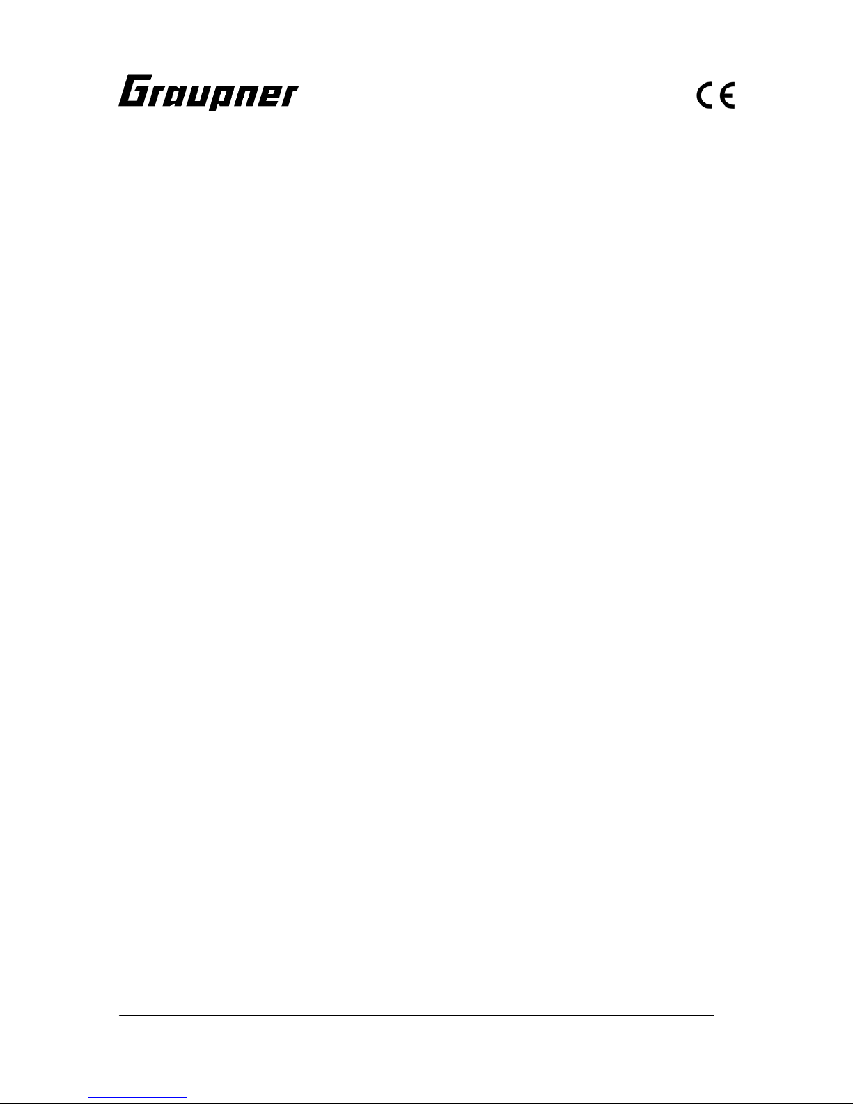
G2 Steckerpolung
Page 7
GRAUPNER GmbH & Co. KG D-73230 KIRCHHEIM/TECK GERMANY
Keine Haftung für Druckfehler. Technische Änderungen vorbehalten! Liability for printing errors excluded. We reserve the right to introduce modifications. Sous réserve de modifications! Nous ne sommes pas responsables d’éventuelles erreurs d’impression! #0059054 04/2008
7
werden, dass das Tochterboot aus der Wanne gleiten kann. Optimal ist eine Stellung wie auf dem Foto (gerade Verlängerung des Winkels der Heckwanne). Sollten Sie dies über den Sender nicht einstellen können, machen Sie sich eine Markierung
am Drehpoti am Sender um diese Position möglichst leicht zu erreichen. Es ist aber technisch nicht
kritisch, wenn die Heckklappe weiter nach unten
fährt, es wäre nur nicht vorbildgetreu. HINWEIS: bei
dem empfohlenen RC-Set sollte das Drehpoti zur
Heckklappen Betätigung verwendet werden, bei einem Computersender mit einstellbaren Servoendstellungen können Sie auch einen Schalter
verwenden. Besser wäre aber ein Drehpoti, da hier
die Heckklappe vorbildgetreu langsam heruntergefahren werden kann.
• Fixieren Sie mit Kabelbindern oder Klebeband die
Kabel im Rumpf. HINWEIS: sie dürfen nicht in den
Drehbereich der Wellenkupplungen geraten können.
• Verlegen Sie die Antenne vom Empfänger im Bereich der Decköffnung im Rumpf und kleben Sie
diese mit Klebeband fest. WICHTIG: Um einen sicheren Empfang zu gewährleisten, sollte das Antennenkabel möglichst weit über der Wasserlinie
liegen und ringförmig um den Rumpf laufen! Der
GFK-Rumpf behindert den Empfang nur sehr minimal. Nach eigenem Ermessen kann auch eine
Stabantenne aus dünnem Draht angebracht werden, dann muss das Antennenkabel um die Länge
der Stabantenne gekürzt werden.
• Verbinden Sie mit dem Verteilerkabel G2 (Best.-Nr.
3068) die beiden Fahrtregler. Legen Sie den Akku
in das Modell, stecken diesen an das Parallelkabel
an und testen Sie die Funktionen der RC-Anlage.
Der Akku muss für den Fahrbetrieb unbedingt fest
fixiert werden, damit er nicht rutschen kann. Kleben
Sie je einen Streifen Klettband an den Akku und in
den Rumpf, diese halten dann den Akku in seiner
Position fest. HINWEIS: Um das Modell in die richtige Wasserlage zu bringen, können Sie den Akku
im Modell verlagern, bis es parallel zur Wasserlinie
liegt. HINWEIS: Auf dem Foto ist die ungefähre Position des Akkus im Rumpf zu erkennen.
Page 8
GRAUPNER GmbH & Co. KG D-73230 KIRCHHEIM/TECK GERMANY
Keine Haftung für Druckfehler. Technische Änderungen vorbehalten! Liability for printing errors excluded. We reserve the right to introduce modifications. Sous réserve de modifications! Nous ne sommes pas responsables d’éventuelles erreurs d’impression! #0059054 04/2008
8
Tochterboot
• Öffnen Sie die mittlere Abdeckung (die mit dem
pilzförmigen Schornstein) des Modells. Sie ist nur
mit doppelseitigem Klebeband fixiert. Zu Wartungszwecken lassen sich auch die beiden Einstiegsluken komplett abnehmen. Auch diese sind mit doppelseitigem Klebeband fixiert. Achten Sie bei späterem Fahrbetrieb darauf, dass das Klebeband noch
ausreichend klebt. Tauschen Sie es sonst aus, geeignet ist z.B. doppelseitiges Klebeband zum Einkleben von Fotos in Fotoalben.
• Löten Sie an das Motorkabel einen BEC-Stecker.
Achten Sie hier unbedingt auf die Motordrehrichtung. Beim Einstecken des Akkus muss der Propeller so laufen, dass das Modell vorwärts fährt. Sichern Sie die beiden Lötstellen mit Isolierband, sie
dürfen keinesfalls elektrisch in Verbindung kommen
können.
• Schrauben Sie an den einarmigen Servohebel einen Gestängeanschluss. Hierzu müssen Sie das
zweite Loch von oben auf Ø2mm aufbohren. Kleben Sie dann das Servo mit Kontaktkleber (z.B.
UHU kraft, Best.-Nr. 1096) in die vorgesehene Halterung im Modell. Führen Sie dann das Rudergestänge in den Gestängeanschluss, stellen das Servo und das Ruder mittig ein und schrauben das
Gestänge fest.
• Montieren Sie dann mit Klettband den Fahrtregler
und Empfänger im Modell. Verlegen Sie die Antenne, vergleichbar wie beim Kreuzer, im Rumpf.
TIPP: für einen besseren Empfang bohren Sie ein
Ø1mm Loch kurz vor dem Mastfuß, führen das Kabel dort durch und kleben die Antenne mit transparentem Klebeband am Mast fest. Legen Sie eine
Schlaufe am Mastfuß, so lässt sich der Mast noch
ausstellen (siehe Foto).
• Der Akku wird unter die hintere Plicht gelegt und
dort mit Klettband fixiert.
Page 9
GRAUPNER GmbH & Co. KG D-73230 KIRCHHEIM/TECK GERMANY
Keine Haftung für Druckfehler. Technische Änderungen vorbehalten! Liability for printing errors excluded. We reserve the right to introduce modifications. Sous réserve de modifications! Nous ne sommes pas responsables d’éventuelles erreurs d’impression! #0059054 04/2008
9
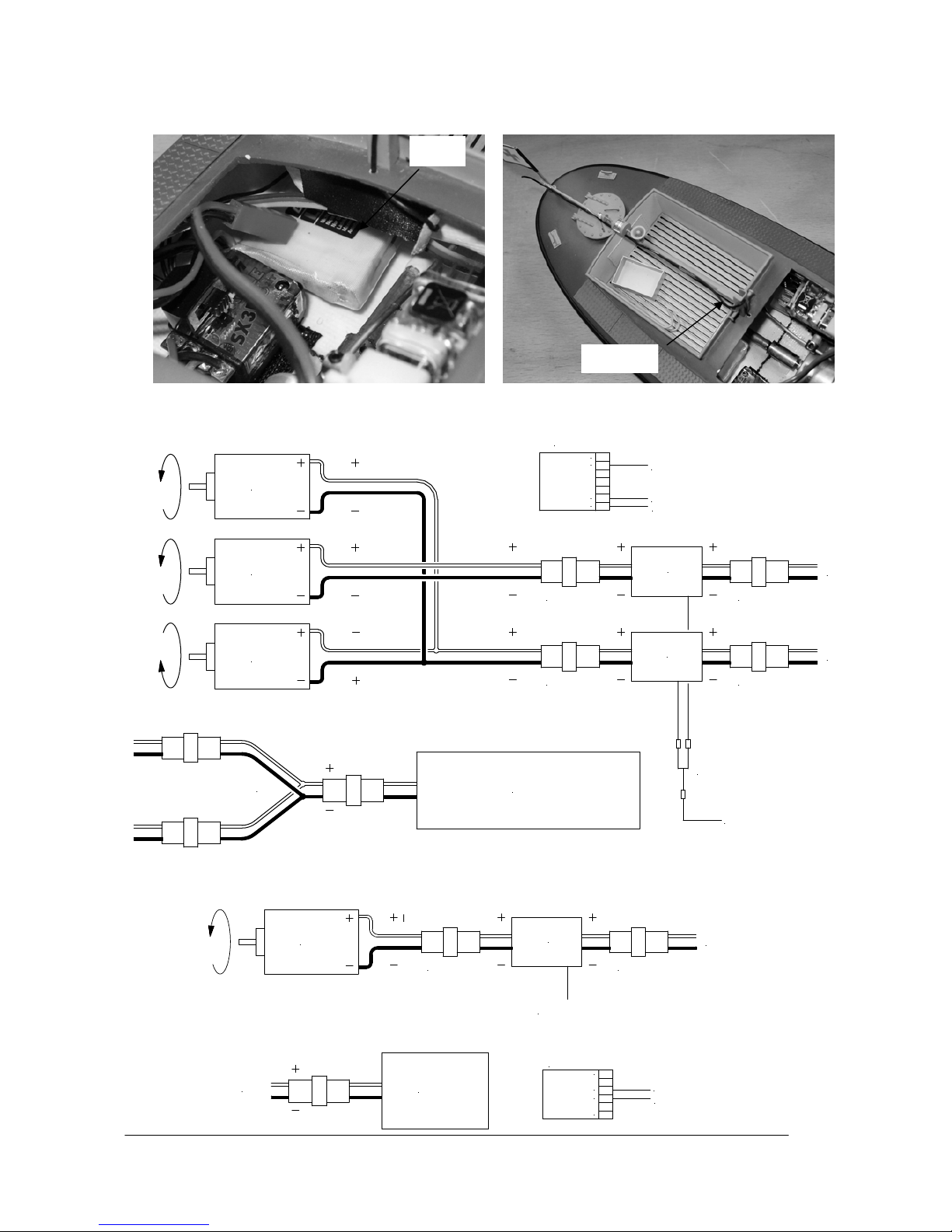
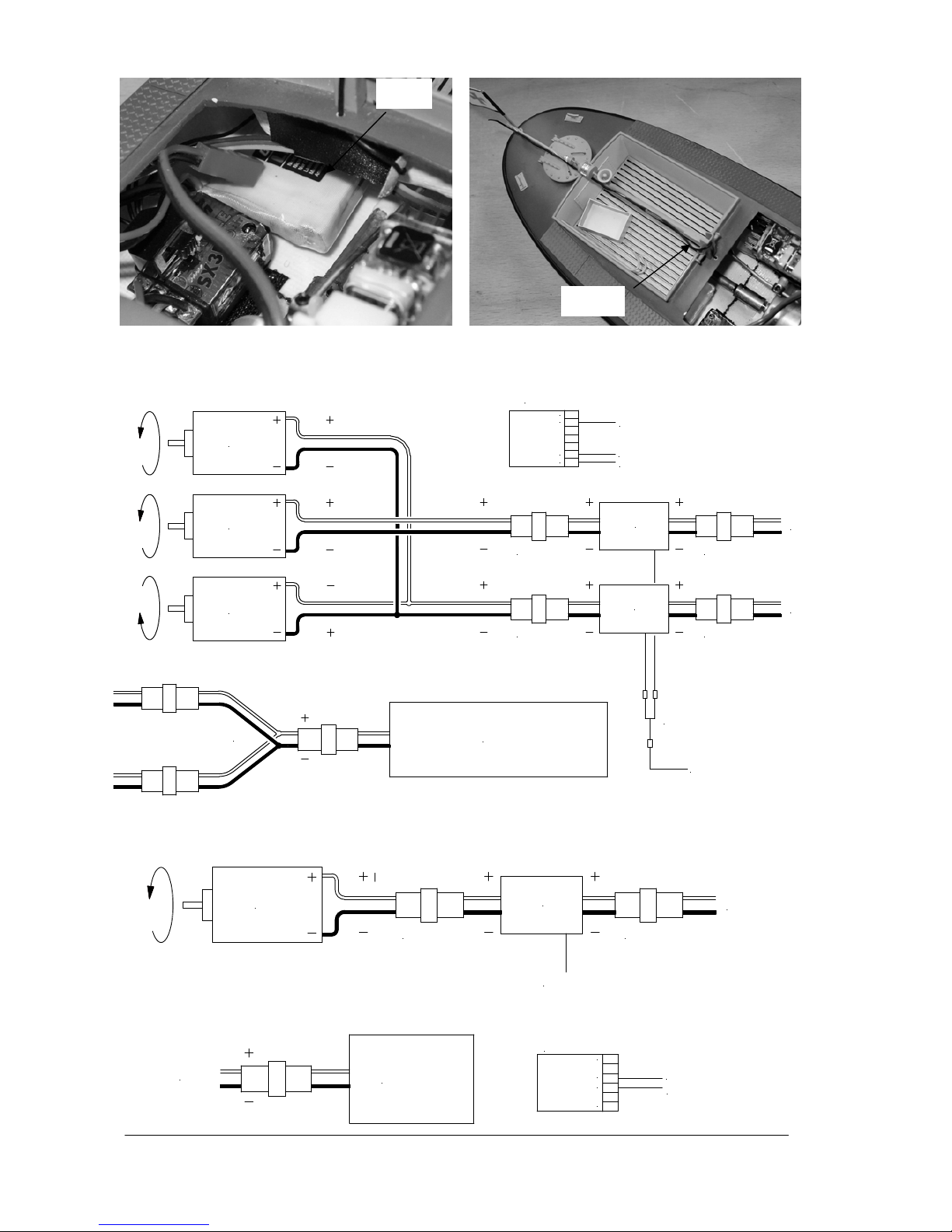
Schaltplan Kreuzer
Schaltplan Tochterboot
Akku
Antenne
Fahrtregler
Mittelmotor
zum Empfänger
3068
Motor
Motor
G2 Stecker G2 Stecker
Motor
Fahrakku
3068
G2 Stecker G2 Stecker
Fahrtregler
Außenmotoren
3068
Servo V-Kabel 3936.11
Empfänger
1
Servo V-Kabel der Fahrtregler
Ruderservo
7
2
6
Winch für Heckklappe
zum Empfänger
Fahrtregler
Akku
Motor
BEC Stecker BEC Stecker
Fahrakku
Fahrtregler
Empfänger
1
3
4
6
Fahrtregler
Ruderservo
Page 10

GRAUPNER GmbH & Co. KG D-73230 KIRCHHEIM/TECK GERMANY
Keine Haftung für Druckfehler. Technische Änderungen vorbehalten! Liability for printing errors excluded. We reserve the right to introduce modifications. Sous réserve de modifications! Nous ne sommes pas responsables d’éventuelles erreurs d’impression! #0059054 04/2008
10
Jungfernfahrt
Laden Sie alle Akkus und testen Sie die Funktionen von beiden Modellen. Kontrollieren Sie, ob alle aufgesteckten Teile fest sitzen. Nun können Sie die Jungfernfahrt starten. Lassen Sie es bei der Jungfernfahrt
langsam angehen, machen Sie sich erst mit dem Fahrverhalten vertraut. Das Modell fährt relativ schnell,
besitzt einen großen Wendekreis und einen langen Bremsweg und sollte daher auf einem geeigneten großen Gewässer eingesetzt werden. Fahren Sie anfangs auch nicht zu weit weg vom Ufer. Testen Sie die
Absetzfunktion des Tochterboots nur in unmittelbarer Nähe zum Ufer. So können Sie noch per Hand eingreifen, falls etwas nicht so funktioniert, wie es soll.
Viel Spaß beim Fahren mit Ihrem Modell Theodor Heuss.
Ersatzteile
Best.-Nr. 2013.6 Schiffsschraubensatz (nur vom Kreuzer)
Ferner wird benötigt (nicht im Lieferumfang enthalten)
Empfohlenes Zubehör (Kreuzer)
Best.-Nr. Bezeichnung
4714 RC-Set X-412 40MHz FM
oder
4725 RC-Set mc-12 40 MHz FM, zusätzlich mit Proportional-Drehmodul Best.-Nr. 4170 ausgestattet
2875 Fahrtregler NAVY V40R (für den Mittelmotor)
2847 Fahrtregler Power V60 (für die Seitenmotoren)
3936.11 Servo V-Kabel, wird nicht beim Einsatz der mc-12 benötigt
2581 Fahrakku Graupner 6N-8000 NiMH
2989 G2-Steckersystem zum Anschluss des Fahrtregler und Akku (2 Stück erforderlich)
3068 Verteilerkabel G2
Je nach Platzierung der RC-Komponenten benötigen Sie Servoverlängerungskabel in unterschiedli-
chen Längen, Best.-Nr. 3935.xx (siehe Hauptkatalog FS)
Empfohlenes Zubehör (Tochterboot)
Best.-Nr. Bezeichnung
4054.10 Micro-Empfänger R 600 FM 40 light, HINWEIS: Sie benötigen einen Empfängerquarz mit den gleichen
Kanal, wie ihn der Sender besitzt.
5114.LOSE Servo C 141
2836.BEC Fahrtregler PURPLE SX3R
7610.2 Fahrakku LiPo 650 7,4V/650mAh
3029.2 BEC-Motoranschlusskabel
1182 Gestängeanschluss
Die Steuerung erfolgt über die Fernsteuerung vom Kreuzer oder über ein separates RC-Set X-408 40MHz FM (Best.-Nr.
4729)
Page 11

GRAUPNER GmbH & Co. KG D-73230 KIRCHHEIM/TECK GERMANY
Keine Haftung für Druckfehler. Technische Änderungen vorbehalten! Liability for printing errors excluded. We reserve the right to introduce modifications. Sous réserve de modifications! Nous ne sommes pas responsables d’éventuelles erreurs d’impression! #0059054 04/2008
11
Operating Instructions for the THEODOR HEUSS model boat, Order No.: 2013
The full-size vessel (text © DGzRS [German Association for the Rescue of the Shipwrecked] Bremen)
The centre of Bremen was definitely busier than on a normal day. It was 12 February 1957, which was a
Friday. Despite the early hour, there were many people at the main railway station of the Hanseatic city to
welcome a special train arriving from Bonn - the Federal capital at the time. The train carried an important
passenger in Professor Theodor Heuss, Federal President and patron of the rescue service, who wanted to
be present at the ceremonial christening of the first ocean-going rescue cruiser of the DGzRS.
Accompanied by DGzRS Chairman, Hermann Helms Snr., and Bremen’s mayor, Wilhelm Kaisen, the Head
of State embarked on the experimental ocean-going cruiser HERMANN APELT, which sailed down the Weser into Bardenfleth, in Lower Saxony. Dense crowds of people lined the river banks and dykes; even the
local schools had given the children the day off.
The destination of this short journey along the Weser was the premises of the Schweers dockyard, which is
Lürssen-Bardenfleth today. Inside the shipbuilding hall, which was beautifully decorated for the occasion,
Hanne Heuss, the Federal President’s daughter-in-law, pronounced the following chri stening poem:
Fahre, Schiff, Sail on, ship,
Du tapf’rer Retter Through tempest steaming,
Durch der Stuerme boeses Wetter, Troubled shipwrecked souls redeeming;
zu dem Bruder, der in Not Save our brothers, who indeed
bis Dein Helfen sich ihm bot - Stand of timely help in need.
dass als grosses Vorbild bliebe: Help us with courageous love
Tapferkeit und Menschenliebe All our fears to rise above
By breaking the mandatory bottle of sparkling wine on the ship’s bow, Frau Heuss christened the new, modern, ocean-going emergency cruiser by the name THEODOR HEUSS; the daughter boat was named
TEDJE.
The THEODOR HEUSS was the first fast ocean-going rescue cruiser with a continuous maximum speed of
20 knots; back in 1957 she was approximately twice as fast as any other all-weather ocean-going rescue
ships operating in Germany or Europe, and is now acknowledged as a milestone in specialist shipbuilding. In
the same year of her commissioning the ocean-going rescue cruiser took part in a presentation at international level at Gdingen, Poland (Gdynia, formerly Gotenhafen), where a meeting of the rescue services of the
Baltic Sea coastal states was held to mark the fiftieth birthday of the Swedish Sea Rescue Association
SSRS. The THEODOR HEUSS was widely admired and praised at the event, especially by the marine rescue experts present.
After the vessel’s christening, the THEODOR HEUSS was initially stationed on the East Frisian island of
Borkum, but was re-located to Laboe on the Kieler Foerde from 1963 until being taken out of service. Under
the stewardship of Wilhelm Eilers, Johann Eberhardt and Johann Eberhardt Jnr. the ocean-going rescue
cruiser proved its worth in numerous rescue missions.
Johann Eberhardt Jnr. joined the crew of the THEODOR HEUSS in 1964, and six years later took control of
the ocean-going rescue cruiser as successor to his Father. Today the 74-year old enjoys reminiscing about
one event in particular: the 1972 Olympic Games: “During the event the various sailing competitions were
secured by a whole fleet of DGzRS units assigned to our district, and overall responsibility for regatta security was assigned to the THEODOR HEUSS; nowadays this task is known as On-Scene Co-ordinator. For
several weeks the world was our guest at the Kieler Foerde, and everything went off peacefully and
smoothly.”
THEODOR HEUSS ocean-going rescue cruiser (DGzRS Construction No.: KRS 2)
Year of building: 1956
Christening: 12 February 1957, at Bardenfleth
Dockyard: Fr. Schweers, Bardenfleth / Unterweser
Dockyard No.: 6320
Call-sign: DBAG
Daughter boat: TEDJE (KRT 2)
Dockyard: Fr. Schweers, Bardenfleth / Unterweser
Dockyard No.: 6332
Call-sign: DA 6214
Page 12

GRAUPNER GmbH & Co. KG D-73230 KIRCHHEIM/TECK GERMANY
Keine Haftung für Druckfehler. Technische Änderungen vorbehalten! Liability for printing errors excluded. We reserve the right to introduce modifications. Sous réserve de modifications! Nous ne sommes pas responsables d’éventuelles erreurs d’impression! #0059054 04/2008
12
Stations:
7 March 1957 to 17 June 1963: Borkum
21 June 1963 to 29 May 1985: Laboe
De-commissioned: June 1985
Namesake:
The German liberal politician Dr. Theodor Heuss (1884 - 1963) was the first President of the Federal Republic of Germany from 1949 to 1959. The name Tedje is an affectionate abbreviation of Theodor.
Conclusion:
In June 1985 the ocean-going rescue cruiser was sold to the private individual P. Spatz of Bremen, minus
her daughter boat. The vessel was duly refitted as a motor-cruiser and accommodation vessel. In 2007 the
ship was still in existence and moored at Bremerhaven, where she was for sale.
In 1986 the daughter boat was renamed the ROLAND, and erected as a technical memorial in front of the
Norddeich rescue hangar. In 1996 the vessel was sold on to a private individual living in the Ruhr region.
The boat now bears its original name TEDJE once more, and is currently undergoing restoration.
The model
This boat is a member of the GRAUPNER PREMIUM line, a series of particularly high-quality ready-made
models with an unprecedented level of detailing for a commercial product.
The core of this high-quality model is the robust moulded GRP hull, complemented by the superstructure and
deck which are constructed from laser-cut ABS parts. Many of the small items are of metal, and almost everything is factory-assembled. The hull, parts of the superstructure, the funnel and fittings are spray-finished
using semi-matt paints, and the decals are already applied. The many details and scale fittings give the boat
an impressive scale appearance. The daughter boat is also designed and prepared to be run independently,
and only has to be fitted out with RC components. The cruiser features a factory-installed winch for the stern
flap function. It is already connected to the stern flap, and is ready to use; all the modeller has to do is adjust
the system to set up the correct end-points.
The large deck opening makes it a simple matter to install the RC components, and the procedure is quickly
completed. To prepare the boat for running all you have to do is install the RC components and the drive
battery, carry out a little soldering, and the model is ready for the water. The same applies to the daughter
boat; the small openings do make it a little tricky to install the radio system, but the procedure is still perfectly
possible.
Specification, production model
Cruiser Daughter boat
Length approx. 1160 mm 325 mm
Beam approx. 265 mm 110 mm
Overall height approx. 560 mm 200 mm (incl. mast)
All-up weight incl. RC approx. 6.5 kg (incl. daughter boat and RC) 410 g
Scale approx. 1 : 20 1 : 20
Manufacturer’s declaration from Graupner GmbH & Co KG
Contents of the manufacturer’s declaration:
If material defects or manufacturing faults should arise in a product distributed by us in the Federal Republic
of Germany and purchased by a consumer (§ 13 BGB), we, Graupner GmbH & Co. KG, D-73230
Kirchheim/Teck, Germany, acknowledge the obligation to correct those defects within the limitations described below.
The consumer is not entitled to exploit this manufacturer’s declaration if the failure in the usability of the
product is due to natural wear, use under competition conditions, incompetent or improper use (including
incorrect installation) or external influences.
This manufacturer’s declaration does not affect the consumer’s legal or contractual rights regarding defects
arising from the purchase contract between the consumer and the vendor (dealer).
Extent of the guarantee
If a claim is made under guarantee, we undertake at our discretion to repair or replace the defective goods.
We will not consider supplementary claims, especially for reimbursement of costs relating to the defect (e.g.
installation / removal costs) and compensation for consequent damages unless they are allowed by statute.
This does not affect claims based on legal regulations, especially according to product liability law.
Page 13

GRAUPNER GmbH & Co. KG D-73230 KIRCHHEIM/TECK GERMANY
Keine Haftung für Druckfehler. Technische Änderungen vorbehalten! Liability for printing errors excluded. We reserve the right to introduce modifications. Sous réserve de modifications! Nous ne sommes pas responsables d’éventuelles erreurs d’impression! #0059054 04/2008
13
Guarantee requirements
The purchaser is required to make the guarantee claim in writing, and must enclose original proof of purchase (e.g. invoice, receipt, delivery note) and this guarantee card. He must send the defective goods to us
at his own cost, using the following address:
Gliders
Brunel Drive, Newark, Nottinghamshire, NG242EG
The purchaser should state the material defect or manufacturing fault, or the symptoms of the fault, in as
accurate a manner as possible, so that we can check if our guarantee obligation is applicable.
The goods are transported from the consumer to us and from us to the consumer at the risk of the consumer.
Duration of validity
This declaration only applies to claims made to us during the claim period as stated in this declaration. The
claim period is 24 months from the date of purchase of the product by the consumer from a dealer in the
Federal Republic of Germany (date of purchase). If a defect arises after the end of the claim period, or if the
evidence or documents required according to this declaration in order to make the claim valid are not presented until after this period, then the consumer forfeits any rights or claims from this declaration.
Limitation by lapse of time
If we do not acknowledge the validity of a claim based on this declaration within the claim period, all claims
based on this declaration are barred by the statute of limitations after six months from the time of implementation; however, this cannot occur before the end of the claim period.
Applicable law
This declaration, and the claims, rights and obligations arising from it, are based exclusively on the pertinent
German Law, without the norms of international private law, and excluding UN re tail law.
Important safety notes
You have acquired a kit which can be assembled into a fully working RC model when fitted out with suitable
accessories. However, we as manufacturers have no control over the way you build and operate your RC
model boat, nor how you install, operate and maintain the associated components, and for this reason we
are obliged to deny all liability for loss, damage or costs which are incurred due to the incompetent or incorrect use and operation of our products, or which are connected with such operation in any way. Unless otherwise prescribed by binding law, the obligation of the GRAUPNER company to pay compensation, regardless of the legal argument employed, is excluded. This includes personal injury, death, damage to buildings,
damage due to loss of business or turnover, interruption of business or other direct or indirect consequent
damage whose root cause was the operation of the model.
The total liability in all cases and under all circumstances is limited to the amount of money which you actually paid for this model.
This model boat is built and operated at the sole and express responsibility of the operator. The only
way to avoid injury to persons and damage to property is to handle and operate the model with the
greatest care and consideration at all times.
Before you run the model for the first time please check that your private third-party insurance covers the
operation of model boats of this kind. If in doubt, take out a special insurance policy designed to cover modelling risks.
These safety notes should be kept in a safe place. If you ever dispose of the model, be sure to pass them on
to the new owner.
The following points are important and must be observed at all times:
• This model is not suitable for young persons under 14 years of age.
• The projecting parts of the model may be sharp, and the aerials and masts could cause eye injuries.
• Bear in mind that tools can be dangerous; always be careful when handling them.
• Never operate the model when there are persons or animals in the water, as its high speed constitutes a
considerable injury hazard.
• Never run your model in protected sites, animal or plant sanctuaries or sites of special scientific interest
(SSSIs). Check with your local authority that the stretch of water you wish to use is suitable for model
boats.
• Never run the boat in salt water.
• Never run the boat in adverse conditions, e.g. rain, storm, strong wind, choppy water or strong currents.
Page 14

GRAUPNER GmbH & Co. KG D-73230 KIRCHHEIM/TECK GERMANY
Keine Haftung für Druckfehler. Technische Änderungen vorbehalten! Liability for printing errors excluded. We reserve the right to introduce modifications. Sous réserve de modifications! Nous ne sommes pas responsables d’éventuelles erreurs d’impression! #0059054 04/2008
14
• Read the instructions provided with your radio control system and accessories, and observe the recommendations.
• Before you run the model check that the radio control system is working reliably, and that all connections
are secure.
• Dry batteries must never be recharged. Only batteries marked as “rechargeable” are safe to recharge.
• Check the range of the radio control system before each session: ask a friend to walk about 100 m away
from the model carrying the transmitter. Your friend will be able to tell you whether all the working functions operate correctly at this range.
• Ensure that the frequency you intend to use is not already in use by other modellers. Never run your
boat if you are not certain that your channel is free.
• Bear in mind that other radio equipment and transmitting stations can cause serious interference to the
model. Ensure that no equipment of this type is being used in the vicinity while you are operating the
model.
• Do not carry out any work on the drive train unless you have disconnected and removed the battery.
• When the drive batteries are connected, keep well clear of the area around the propellers, and make
sure any spectators do the same.
• Do not be tempted to exceed the recommended operating voltage. Higher voltages may cause the motor
or speed controller to overheat, and the electrical cables may even melt. If this should happen, the model
could easily be completely ruined.
• Check that all the drive train components work smoothly and freely. This applies in particular when the
boat is running, as leaves and other debris may get caught in the power system components. The motor
and speed controller could then be ruined by overloading.
• Dry cells and rechargeable batteries must never be short-circuited. Do not allow them to come into direct
contact with water.
• Remove the rechargeable battery and the dry cells in the transmitter and receiver pack if the model is to
be transported, or will not be used for a long period.
• Do not subject the model boat to high levels of humidity, heat, cold or dirt.
• Secure the model and your RC equipment carefully when transporting them. They may be seriously
damaged if they are free to slide about.
• Please ensure that the daughter boat is always ready to run when it is on board the cruiser; this enables
you to run the smaller boat ‘back home’ if the stern flap is opened accidentally. Should you wish to run
the cruiser with the daughter boat switched off, we suggest that you take steps to prevent the stern flap
opening by chance, e.g. by holding it closed with clear adhesive tape.
• The daughter boat should only be operated on very smooth water, as any waves tend to fill the two de-
pressions in the deck with water, and this makes the boat heavier. The model’s increased draught may
then cause water to get inside the hull, and it could sink.
• Never operate the boat in moving water (e.g. a river), as the model would drift away downstream if a
fault were to occur.
• If you have to salvage the model, take care not to risk your own life or that of others.
• Take particular care to ensure that the boat is completely watertight, as it will sink if too much water en-
ters the hull. Check the model for damage before every run, and ensure that water cannot penetrate
through the shaft bearings and rudder bush.
• Allow the boat to dry out thoroughly after each session.
•
Be sure to check repeatedly during the first run that the shaft system is watertight. If water enters the hull
through the shaft tubes, remove the shafts and lubricate the tubes with plenty of grease, Order No. 570.
• NOTE: the electric motors installed in the models must not be discarded in the household rubbish. When
they are worn out, they should be removed from the boats and taken to your local collection point for
electrical waste.
Care and maintenance
• Clean the models carefully after every run, and remove any water which penetrates the hull. If water gets
into the RC components, dry them out carefully and send them to your nearest GRAUPNER Service
Centre for checking.
• Clean the model and transmitter using suitable cleaning agents only. All you need is a lint-free cloth.
Never use chemical cleaners, solvents, methylated spirits, white spirit or similar.
• Lubricate the propeller shafts at the close of each session by applying a small drop of oil to the bearings.
The outer shaft bearings at the propellers must also be lubricated. Use a type of oil which does not soil
or contaminate water, e.g. Order No. 206. At the end of the season we recommend that you remove the
propeller shafts and re-lubricate them using water-neutral grease, e.g. Order No. 570.
• Maintenance of the daughter boat simply involves a drop of oil at the bearing end of the stern tube after
each session; it is not necessary to remove the shaft for this.
Page 15

GRAUPNER GmbH & Co. KG D-73230 KIRCHHEIM/TECK GERMANY
Keine Haftung für Druckfehler. Technische Änderungen vorbehalten! Liability for printing errors excluded. We reserve the right to introduce modifications. Sous réserve de modifications! Nous ne sommes pas responsables d’éventuelles erreurs d’impression! #0059054 04/2008
15
• We recommend that you should also apply a drop of oil to the rollers on which the daughter boat runs, to
ensure that they rotate freely. A small drop of oil at the stern flap bearings can do no harm.
Assembling the model
• Carefully unpack the models and the boatstand.
• Remove the daughter boat from the cradle; the method of installing the RC components in the smaller
model is described separately in these instructions.
• The method of connecting the various leads to the receiver is shown in schematic form in the wiring
diagrams which are provided for both models. We assume that you are using the recommended receivers (R700 for the cruiser, R600 light for the daughter boat). If you prefer to use different types, you must
ensure that no channels are duplicated at the two receivers, as this would make it impossible to control
the models separately.
• Place the models on the stands provided and leave them there whilst carrying out all the procedures
described below.
Cruiser
• Cautiously disconnect the aerial link wire as
shown, then disconnect the four aerial wires at
the mast. The superstructure can now be carefully lifted up and off.
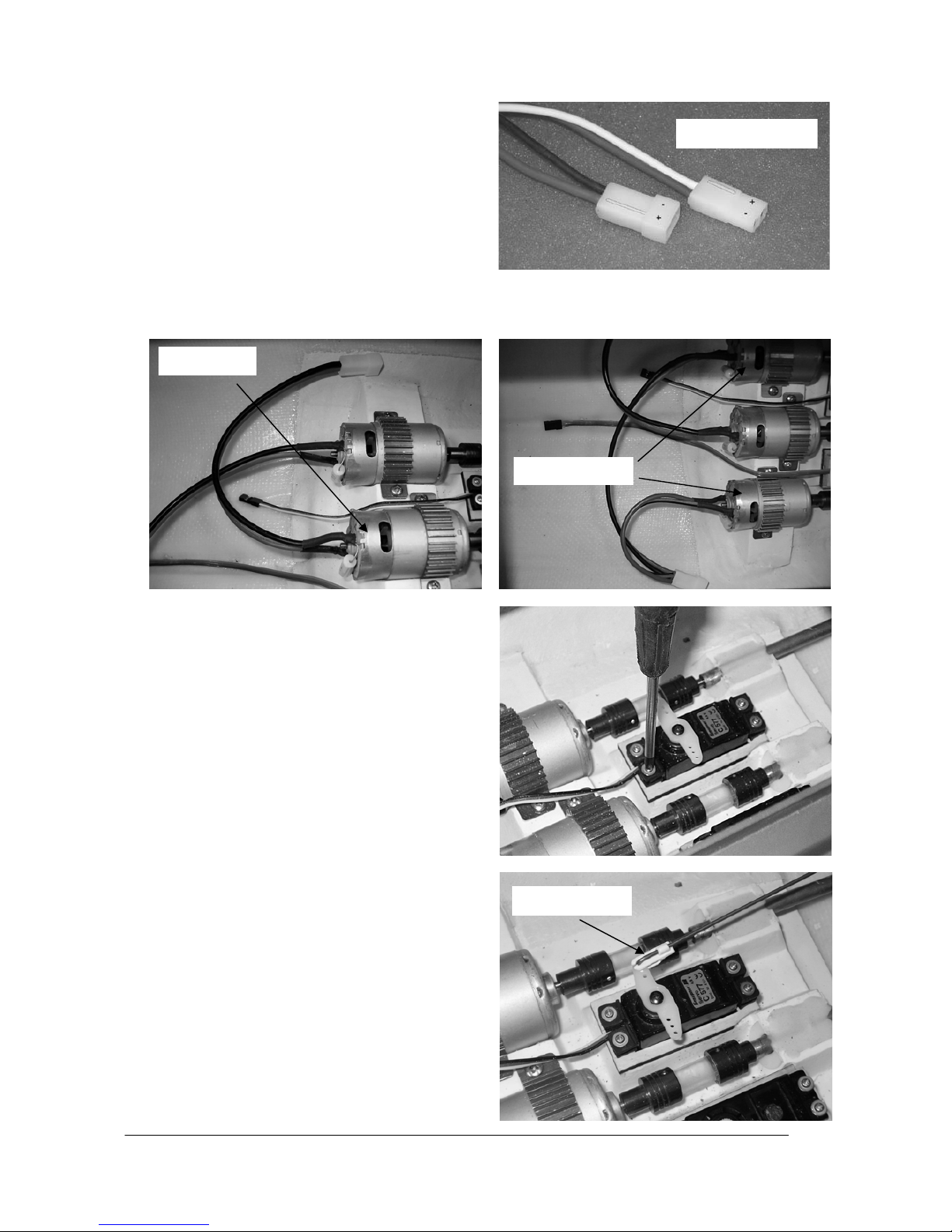
• Solder a G2 plug to the wires attached to the
centre motor, then solder a G2 plug to each of
the two outer motors, referring to the wiring diagram on page 9 (+ is red (light in the drawing), is black). Ensure that the motors spin in the correct direction: when the battery is connected, the
propellers should rotate in such a way that the
model would be propelled forward. NOTE: the
raised lug on the plastic housing of all G2 connectors should always be the positive terminal
(red wire). If you keep consistently to this principle, your batteries and speed controllers will be
interchangeable, and the system will be protected
against accidental reversed polarity. To make it
easier to solder the plug, it is advisable to use
one of the following methods, as this will reduce
the likelihood of damaging the model with the
soldering iron. METHOD 1: remove the motors
from the model by first undoing the grubscrews in
the shaft couplings (motor side only). Undo the
motor screws in the retaining straps - don’t remove them completely - and withdraw the motors. The motors can later be re-installed simply
by reversing the sequence of operations stated
above. METHOD 2: use a “third hand” (a special
positionable part-holding tool) to hold the plug,
and use the soldering iron directly inside the hull
(see photo).
Disconnect
Disconnect
Page 16

GRAUPNER GmbH & Co. KG D-73230 KIRCHHEIM/TECK GERMANY
Keine Haftung für Druckfehler. Technische Änderungen vorbehalten! Liability for printing errors excluded. We reserve the right to introduce modifications. Sous réserve de modifications! Nous ne sommes pas responsables d’éventuelles erreurs d’impression! #0059054 04/2008
16
• Check that the propellers and the screws in the
shaft couplings (arrow in the photo) are tight, as
they may have come loose in transit; carefully retighten them if necessary. NOTE: the propellers
are not metal; they are made of metallised plastic.
This means that the grubscrews should be tightened with the greatest care, otherwise you will
strip the threads in the propellers. The grubscrews
do not hold the propellers on the shaft by pressure; there are flats ground into the shaft, and the
grubscrews simply engage on the flats to prevent
the propellers rotating. NOTE: if the grubscrews are loose, apply a drop of thread-lock fluid to them, e.g.
UHU schraubensicher, Order No. 952, as vibration could cause them to work loose again while the boat
is running.
• Fit the double-ended servo output lever on the
rudder servo. Press the rubber grommets (supplied with the servo) into the mounting lugs of the
rudder servo, and push the brass spacer sleeves
through them from the underside. Fit the servo in
the opening in the internal hull, and drill 1 mm Ø
pilot-holes through the mounting lug holes before
securing the servo using the retaining screws
supplied. IMPORTANT: take care not to damage
the servo lead when you fit the screws.
• Set the rudder servo to centre from the transmitter.
Move the rudder blades to the “straight ahead”
position, and adjust the rudder pushrod in such a
way that the clevis pin fits exactly in the hole in the
servo output arm.
• Attach Velcro (hook-and-loop) tape to the speed
controllers and the receiver, and fix these components to the inside of the hull wall in the vicinity of
the motors.
• Connect the rudder servo, the stern flap servo and
the speed controller to the receiver. NOTE: the
two speed controllers are connected using a Ylead (Order No. 3936.11); if you have a computer
radio control system, an alternative method is to
set up a free mixer at the transmitter.
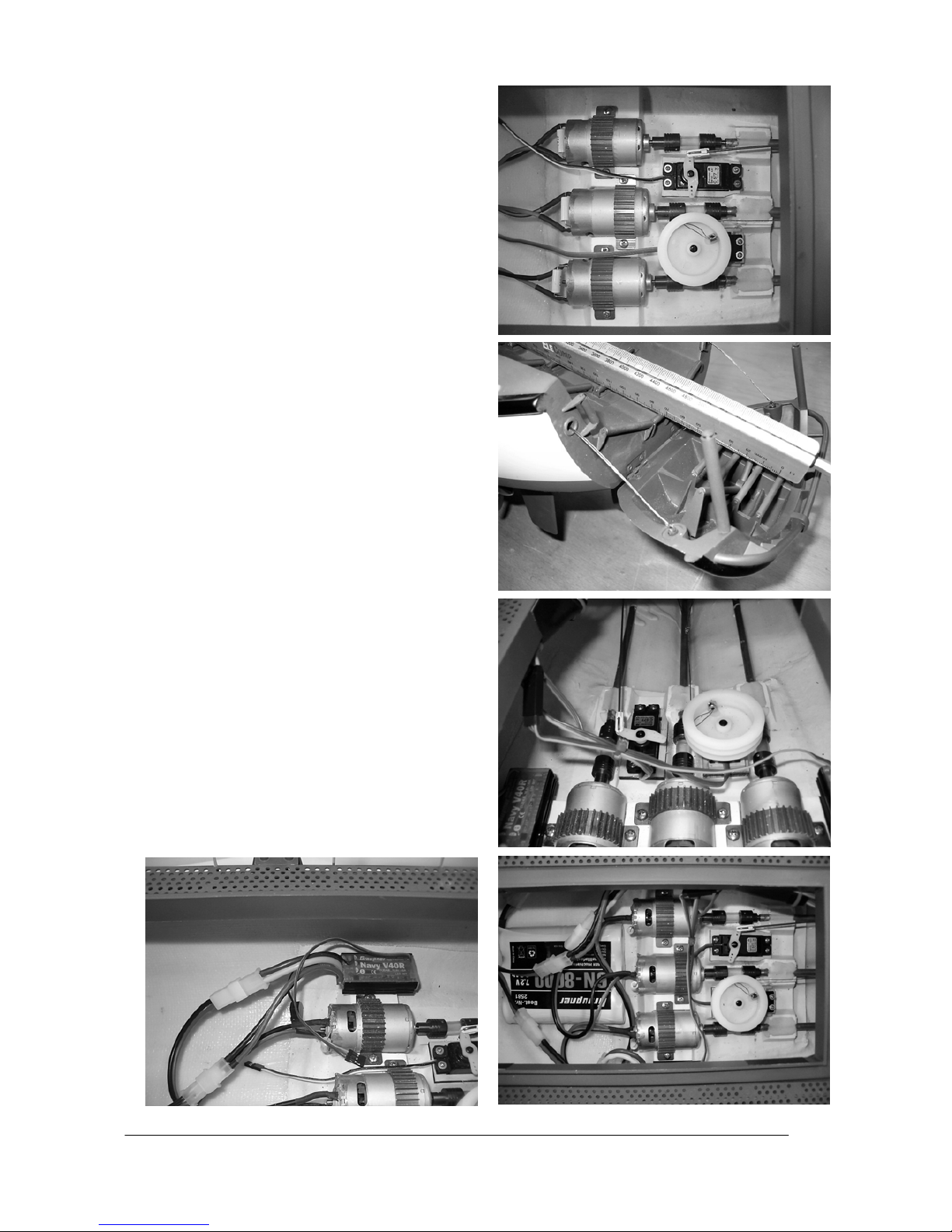
• Adjust the stern flap in such a way that the upper
end-point (= stern flap closed) is reached without
the winch being under load. If you cannot achieve
this using the transmitter’s adjustment facilities,
unscrew the retaining screw in the winch drum,
and adjust the position of the drum on the servo so
G2 connector polarity
Centre motor
Outside motors
Safety clip
Page 17

GRAUPNER GmbH & Co. KG D-73230 KIRCHHEIM/TECK GERMANY
Keine Haftung für Druckfehler. Technische Änderungen vorbehalten! Liability for printing errors excluded. We reserve the right to introduce modifications. Sous réserve de modifications! Nous ne sommes pas responsables d’éventuelles erreurs d’impression! #0059054 04/2008
17
that the winch is not under load when the stern
flap is closed. The lower end-point (= stern flap
open) should be set up so that the daughter boat
can slide out of the cradle reliably. The optimum
arrangement is shown in the photo (straight continuation of the angle of the stern cradle). If you
cannot achieve this using the tr ansmitter, mark a
point on the rotary pot on the transmitter to make it
as easy as possible to select this position. However, in technical terms it is not disastrous if the
stern flap moves down further than described; it
would simply look slightly ‘non-scale’. NOTE: if
you are using the recommended RC system, the
rotary pot should be used to operate the stern flap;
if you are using a computer transmitter with variable servo end-points, you can use a switch instead. However, a rotary pot is still the better option, as it allows you to lower the stern flap at a
low scale speed.
• Secure the cables neatly inside the hull using ca-
ble ties or Velcro tape. NOTE: ensure that the
leads cannot foul the shaft couplings.
• Deploy the receiver aerial under the deck support
flange inside the hull, and tape it in place securely.
IMPORTANT: to ensure reliable reception, the aerial wire must be as high as possible above the
waterline, and should run round the hull in a broad
curve; the GRP material only has a very slight adverse effect on radio reception. If you prefer, you
can install a vertical whip aerial made of thin, stiff
wire. If you do this, shorten the flexible aerial attached to the receiver by the same length as the
whip, then solder the two together.
• Connect the two speed controllers using the G2
distributor lead (Order No. 3068). Place the battery
in the model, connect it to the parallel cable, and
check the working systems. The battery must be
fixed securely so that it cannot slip out of position
when the boat is running. Stick a strip of Velcro
tape to the battery, and the mating strip in the hull;
this will prevent it shifting. NOTE: the battery must
be positioned in the hull in such a way that the
vessel floats level at the marked waterline. NOTE:
the photograph shows the approximate position of
the battery.
Page 18

GRAUPNER GmbH & Co. KG D-73230 KIRCHHEIM/TECK GERMANY
Keine Haftung für Druckfehler. Technische Änderungen vorbehalten! Liability for printing errors excluded. We reserve the right to introduce modifications. Sous réserve de modifications! Nous ne sommes pas responsables d’éventuelles erreurs d’impression! #0059054 04/2008
18
Daughter boat
• Open the central hatch (the one with the integral
mushroom-shaped funnel) on the boat; it is only
held in place by double-sided adhesive tape. For
maintenance purposes the two entry hatches can
also be removed completely; these are also secured with double-sided tape. When subsequently
running the boat, please ensure that the tape still
has adequate adhesion. If you are not sure, replace it using the type of double-sided tape intended for sticking photos in photograph albums.
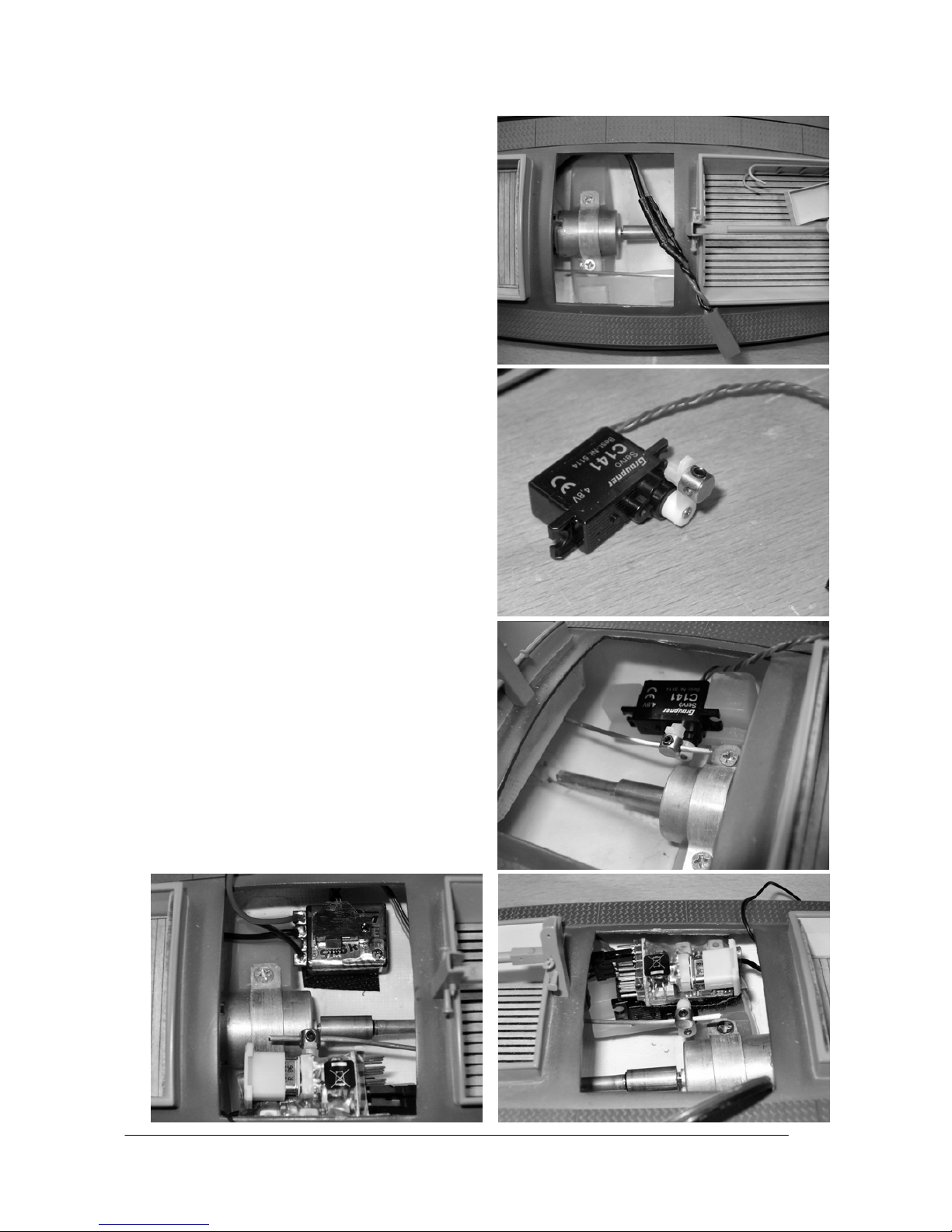
• Solder a BEC connector to the motor wires, taking
particular care to ensure that the motor shaft spins
in the correct direction. When you connect the
battery, the propeller must rotate in such a way
that the boat would move forward. Wrap insulating
tape round the soldered joints at the battery terminals; it is essential that they cannot make electrical contact with each other.
• Mount a swivel pushrod connector on the single-
ended servo output arm as shown in the photograph. You will need to open up the second hole
from the outside using a 2 mm Ø drill. Stick the
servo in the integral servo recess in the model using contact glue (e.g. UHU kraft, Order No. 1096).
Slip the rudder pushrod through the swivel connector, set the servo and the rudder to centre, and
secure the pushrod by tightening the grubscrew.
• Fix the speed controller and the receiver inside
the hull using Velcro tape. Deploy the receiver aerial inside the hull in a similar manner to the
cruiser. TIP: for better reception drill a 1 mm Ø
hole just forward of the mast base, thread the aerial wire through it and stick it to the mast using
clear adhesive tape. Leave a loop of wire at the
base of the mast so that it can still be withdrawn
(see photo).
• The battery should be installed below the rear
cockpit, and secured in that position with Velcro
tape.
Page 19
GRAUPNER GmbH & Co. KG D-73230 KIRCHHEIM/TECK GERMANY
Keine Haftung für Druckfehler. Technische Änderungen vorbehalten! Liability for printing errors excluded. We reserve the right to introduce modifications. Sous réserve de modifications! Nous ne sommes pas responsables d’éventuelles erreurs d’impression! #0059054 04/2008
19
Wiring diagram, cruiser
Wiring diagram, daughter boat
Accu
Aerial
Speed controller,
centre motor
to receive r
3068
Motor
Motor
G2 connector G2 connector
Motor
Drive battery
3068
G2 connector G2 connector
Speed controller,
outer motors
3068
Servo Y-lead, No. 3936.1 1
Receiver
1
Servo Y -lead for speed controllers
Rudder servo
7
2
6
Stern flap winch
to receiv er
Speed controller
Drive battery
Motor
BEC connector BEC connector
Drive battery
Speed controller
Receiver
1
3
4
6
Speed controller
Rudder servo
Page 20

GRAUPNER GmbH & Co. KG D-73230 KIRCHHEIM/TECK GERMANY
Keine Haftung für Druckfehler. Technische Änderungen vorbehalten! Liability for printing errors excluded. We reserve the right to introduce modifications. Sous réserve de modifications! Nous ne sommes pas responsables d’éventuelles erreurs d’impression! #0059054 04/2008
20
Maiden run
Charge up all the batteries and test the working systems of both models one by one. Ensure that all the parts
which are not permanently attached are firmly seated. Now you are ready for the boat’s maiden run. The
Theodor Heuss is fairly fast, has a large turning circle and takes a considerable time to slow down; it therefore needs to be operated on a large stretch of water. Don’t allow the boat to travel too far away from the
bank. When testing the daughter boat lowering system, keep the cruiser very close to the bank; this gives
you the chance to intervene manually if something fails to work as it should.
We hope you have many hours of pleasure running your model of the Theodor Heuss.
Replacement parts
Order No. 2013.6 Replacement propeller set (cruiser only)
You will also need the following items (not included in the set)
Recommended accessories (cruiser)
Order No. Description
4714 X-412 FM RC set, 40 MHz
or
4725 mc-12 FM RC set, 40 MHz, fitted with optional rotary proportional module,
Order No. 4170
2875 NAVY V40R speed controller (central motor)
2847 Power V60 speed controller (outer motors)
3936.11 Servo Y-lead; not required if using the mc-12 RC system
2581 Graupner drive battery, 6N-8000 NiMH
2989 G2 connector system for connecting the speed controller and battery (two
required)
3068 G2 distributor lead
You will need servo extension leads of different lengths, Order No. 3935.xx
(see main FS catalogue), according to the location of the RC components in
the hull.
Recommended accessories (daughter boat)
Order No. Description
4054.10 R 600 light FM 40 MHz receiver, NOTE: you will need a receiver crystal with
the same channel number as that installed in the transmitter.
5114.LOSE C 141 servo
2836.BEC PURPLE SX3R speed controller
7610.2 LiPo 650 drive battery, 7.4 V / 650 mAh
3029.2 BEC motor lead
1182 Swivel pushrod connector
The daughter boat is controlled either with the same transmitter used for the cruiser, or with a separate X408 40 MHz RC system (Order No. 4729).
Page 21

GRAUPNER GmbH & Co. KG D-73230 KIRCHHEIM/TECK GERMANY
Keine Haftung für Druckfehler. Technische Änderungen vorbehalten! Liability for printing errors excluded. We reserve the right to introduce modifications. Sous réserve de modifications! Nous ne sommes pas responsables d’éventuelles erreurs d’impression! #0059054 04/2008
21
Instructions d’utilisation pour le modèle THEODOR HEUSS, Réf. N° 2013
Description de l’original (Bref historique)
Le Croiseur a été baptisé le 12.02.1957 du nom du Président de la République Fédérale de cette époque
Theodor Heuss. Le Canot embarqué a été baptisé Tedje, une déclinaison en Allemagne du Nord du prénom
Theodor. Le Theodor Heuss servit de 1957 à 1963 à Borkum et de 1963 à 1985 à Laboe. Le Croiseur a été
ensuite vendu et navigue encore aujourd’hui comme Yatch sous le nom de Frido Spatz.
Le Canot embarqué se trouve de même en possession privée depuis 1996 et sera également remis en état
de navigation après restauration. Il était préalablement en exposition devant les entrepôts de sauvetage à
Norddeich.
Le Theodor Heuss qui se trouve au musée Allemand de Munich est le Sistership rebaptisé H.H. Meier.
Croiseur THEODOR HEUSS (Numéro DGzRS : KRS 2)
Année de construction:
1956
Lancement: 12. Février 1957 à Bardenfleth
Chantier: Fr. Schweers, Bardenfleth/Unterweser
N° du Chantier 6320
Identification DBAG
Canot embarqué TEDJE (KRT 2)
Chantier: Fr. Schweers, Bardenfleth/Unterweser
N° du Chantier 6332
Identification DA 6214
Description du modèle
Ce modèle fait partie de la PREMIUM-Line GRAUPNER, cette série de modèles finis d’une très haute qualité
dont le super détaillage n’a jamais été atteint jusqu’alors.
Pour obtenir cette exécution de haute qualité, la coque est en solide fibre de verre, les superstructures et le
pont sont des pièces en ABS découpées au Laser et les nombreuses petites pièces fabriquées en métal
sont déjà montées. La coque, les superstructures, lé cheminée et les pièces d’accastillage sont peintes au
pistolet avec des peintures satinées et la décoration est posée. Grâce aux nombreux détails et aux pièces
d’accastillage, le modèle à une allure particulièrement réaliste. Le Canot embarqué est aussi préparé pour
une utilisation séparée et devra seulement être équipé des éléments R/C. Un treuil est intégré en fabrication
pour la fonction de la trappe de poupe et il est déjà relié avec celle-ci. Il reste ici simplement au modéliste à
effectuer les réglages sur les deux extrémités de course.
Le montage de l’équipement R/C est facile et rapide à effectuer grâce à une ouverture suffisamment grande
dans le pont. Pour mettre le modèle en ordre de navigation, il suffit d’installer les éléments R/C et l’accu de
propulsion, ainsi qu’à effectuer quelques petits travaux de soudure. Ceci vaut également pour le Canot embarqué : l’installation des éléments R/C au travers des petites ouvertures est naturellement un peu plus difficile, mais tout à fait possible.
Caractéristiques techniques des modèles de série
Croiseur Canot embarqué
Longueur, env. 1160mm 325mm
Largeur, env. 265mm 110mm
Hauteur totale, env. 560mm 200mm (avec le mât)
Poids total ave R/C² 6,5 Kg (avec Canot embarqué et R/C) 410 g.
Echelle de reproduction, env. 1 :20 1 :20
Déclaration du fabricant de la Firme Graupner GmbH & Co KG
Contenu de la déclaration
Lorsqu’un article que nous distribuons dans la République Fédérale d’Allemagne acquis par un consommateur (§ 13 BGB) présente un défaut de matière ou de fabrication, nous la Firme Graupner GmbH & Co. KG,
Kirchheim Teck, prenons en charge la suppression du défaut de l’article dans les conditions ci après.
Le consommateur ne peut pas valider le droit de déclaration du fabricant lorsque le défaut de l’article provient d’une usure naturelle, d’une utilisation dans des conditions de compétition, d’une mauvaise utilisation
Page 22

GRAUPNER GmbH & Co. KG D-73230 KIRCHHEIM/TECK GERMANY
Keine Haftung für Druckfehler. Technische Änderungen vorbehalten! Liability for printing errors excluded. We reserve the right to introduce modifications. Sous réserve de modifications! Nous ne sommes pas responsables d’éventuelles erreurs d’impression! #0059054 04/2008
22
(incluant le montage) ou d’influences extérieures.
Cette déclaration du fabricant laisse inchangés le droit et les réclamations légales ou contractuelles du
consommateur provenant du contrat d’achat vis à vis de son vendeur (le détaillant).
Etendue de la garantie
En cas de garantie, nous faisons le choix de réparer ou d’échanger la marchandise défectueuse. Toutes
autres réclamations, particulièrement sur le remboursement des coûts engendrés par le défaut (par ex. coûts
de montage/démontage) et la compensation de dommages provoqués en conséquence – même autorisés
légalement – sont exclues. Les réclamations provenant des réglementations légales, en particulier selon la
loi de la responsabilité du fabricant, ne seront pas ici abordées.
Droit à la garantie
L’acheteur peut faire valoir le droit à la garantie en joignant le bon d’achat original (par exemple facture, ticket de caisse, bon de livraison) et cette carte de garantie. Il doit en outre retourner la marchandise défectueuse à ses frais à l’adresse suivante :
GRAUPNER Service France
86 rue St Antoine
F-57601 Forbach-Oeting
L’acheteur doit indiquer concrètement le défaut de matière ou de fabrication ou le symptôme du défaut pour
permettre l’examen de notre devoir de garantie.
Le transport du produit de chez le consommateur à chez nous, tout comme le transport du retour se font aux
risques et périls du consommateur.
Durée de validité
Cette déclaration est seulement valable pour la période accordée aux réclamations provenant de cette déclaration. Le délai de réclamation est de 24 mois à partir de la date de l’achat du produit par le consommateur chez un commerçant en République Fédérale d’Allemagne (date d’achat). Si les défauts sont signalés après le délai de réclamation autorisé ou bien si les preuves ou les documents pour faire valoir les défauts selon cette déclaration sont présentés après le délai de réclamation, l’acheteur n’a aucun droit de réclamation ou requêtes en provenance de cette déclaration.
Prescription
Tant que nous ne reconnaissons pas la réclamation à faire valoir dans la période de réclamation accordée
dans le cadre de cette déclaration, l’ensemble des réclamations de cette déclaration sont prescrites pendant
6 mois à partir de leur validation, cependant pas avant la fin du délai de réclamation.
Droit applicable
Dans le cadre de cette déclaration et des réclamations, des droits et devoirs, qui en résultent, seul et uniquement le Droit matériel allemand s’applique, sans possibilité d’utiliser les normes du Droit privé international et celles de la Commission du Droit de vente des Nations Unies.
Conseils de sécurité importants
Vous avez fait l'acquisition d'un modèle avec les accessoires correspondants qui vont vous permettre la
réalisation d'un bateau radiocommandé. Le respect des instructions de montage et d'utilisation relatives au
modèle ainsi que l'installation, l'utilisation et l'entretien des éléments de son équipement ne peuvent pas être
surveillés par la Firme GRAUPNER. C'est pourquoi nous déclinons toute responsabilité concernent les pertes, les dommages ou les coûts résultants d'une mauvaise utilisation ou d'un fonctionnement défectueux.
Tant qu'elle n'y a pas été contrainte par le législateur, la responsabilité de la Firme GRAUPNER n'est aucunement engagée pour les dédommagements (incluant les dégâts personnels, les cas de décès, la détérioration de bâtiments ainsi que le remboursement des pertes commerciales dues à une interruption d'activité ou
à la suite d'autres conséquences directes ou indirectes) provenant de l'utilisation du modèle.
L'ensemble de sa responsabilité est en toutes circonstances et dans chaque cas strictement limité au montant que vous avez réellement payé pour ce modèle.
L'utilisation du modèle se fait uniquement aux risques et périls de son utilisateur. Seule une utilisation prudente et responsable évitera de causer des dégâts personnels et matériels.
Avant la première utilisation du modèle, vérifiez si votre assurance personnelle couvre ce genre de risques.
Contractez le cas échéant une assurance spéciale pour l'utilisation des modèles réduits radio c ommandés.
En cas de revente du modèle, ces conseils de sécurité devront être impérativement remis à l'acheteur.
Page 23

GRAUPNER GmbH & Co. KG D-73230 KIRCHHEIM/TECK GERMANY
Keine Haftung für Druckfehler. Technische Änderungen vorbehalten! Liability for printing errors excluded. We reserve the right to introduce modifications. Sous réserve de modifications! Nous ne sommes pas responsables d’éventuelles erreurs d’impression! #0059054 04/2008
23
Les points suivants devront être impérativement observés:
• Ce modèle ne convient pas aux enfants en dessous de 14 ans.
• Certaines pièces sur le modèle peuvent être coupantes et les antennes ou les mâts peuvent provoquer
des blessures aux yeux.
• Veillez aux dangers possibles avec l’utilisation des outils.
• Ne faites jamais naviguer le modèle dans des eaux où se trouvent des personnes ou des animaux, car
autrement il existe un sérieux danger de blessure pour eux.
• Ne faites pas naviguer votre modèle sur des eaux situées dans une nature protégée. Informez-vous
auprès de votre commune s’il existe un plan d’eau autorisé pour la navigation des modèles de bateaux.
• Ne naviguez jamais dans de l’eau salée.
• Ne naviguez jamais par de mauvaises conditions atmosphériques, par ex. sous la pluie, un orage, un
vent fort, un fort clapot ou dans une eau courante, etc…
• Observez les instructions d’utilisation de votre ensemble R/C et de ses accessoires.
• Si des piles sèches sont utilisées pour l’alimentation de l’ensemble R/C, celles-ci ne devront jamais être
rechargées. Seuls les accus peuvent être rechargés.
• Avant de faire naviguer le modèle, vérifiez le parfait fonctionnement de l’installation R/C ainsi que
la liaison sûre et ferme de tous les connecteurs.
• La portée de l’installation R/C devra avoir été vérifiée avant de commencer la navigation. Pour cela,
éloignez-vous avec le modèle et la réception en contact à env. 100 m de l’émetteur tenu et manipulé par
un aide. A cette distance, toutes les fonctions doivent être transmises sans problème.
• Assurez-vous que le canal de la fréquence que vous utilisez est libre ; ne naviguez jamais tant que vous
n’êtes pas sûr qu’il n’est pas déjà utilisé.
• Notez que des appareils radio ou d’autres émetteurs R/C peuvent fortement perturber les fonctions du
modèle. Veillez si possible à ce qu’aucun de ces appareils ne soit utilisé à proximité pendant que vous
faites naviguer le modèle.
• Travaillez sur les éléments de la propulsion lorsque les accus de propulsion ne sont pas connectés.
• Lorsque les accus de propulsion sont connectés, ne vous tenez jamais vous-même ou d’autres person-
nes dans le champ de rotation des hélices, car il existe dans cette zone un sérieux danger de blessure.
• Ne dépassez pas la tension d’alimentation conseillée. Une tension trop élevée peut faire surchauffer les
moteurs ou le régulateur de vitesse en faisant fondre les fils électriques ; le modèle pourra ainsi prendre
feu et être détruit.
• Veillez à la libre rotation de tous les éléments de la propulsion. Ceci vaut particulièrement durant la navi-
gation, car des feuilles ou d’autres débris flottants peuvent bloquer la propulsion ; dans un tel cas, les
moteurs ou le régulateur de vitesse pourront être détruits par une surcharge.
• Les batteries et les accus ne devront pas être mis en court-circuit, ni en contact direct avec l’eau
• Retirez l’accu de propulsion du modèle et la batterie de l’émetteur durant son transport et lorsqu’il n’est
pas utilisé.
• N’exposez pas le modèle à une forte humidité, à une chaleur ou un froid excessifs ainsi qu’aux salissu-
res.
• Protégez le modèle et les éléments R/C contre tout risque de détérioration par des chocs durant son
transport.
• Veillez à ce que le Canot embarqué sur le Croiseur soit toujours fonctionnel durant la navigation au cas
où il serait largué par une ouverture imprévue de la trappe de poupe. SI vous voulez naviguer sans le
Canot embarqué fonctionnel, vous devrez fermer la trappe de poupe contre un risque d’ouverture involontaire, par ex. avec du ruban adhésif transparent.
• Le Canot embarqué devra naviguer uniquement sur une eau lisse, car la moindre vague pourra
s’écouler dans les deux dépressions dans le pont et alourdir ainsi le modèle. L’au infiltrée dans le modèle augmentera le tirant d’eau et il pourra s’enfoncer et se retourner.
• Ne faites pas naviguer le modèle dans une eau courante (Par ex. une rivière) ; notez qu’en raison d’une
éventuelle défectuosité, il pourra dériver.
• Ne vous mettez pas vous-même en danger ou quelqu’un d’autre pour une éventuelle tentative de
récupération du modèle.
• Veillez particulièrement à la parfaite étanchéité des modèles. Un modèle de bateau peut couler à la suite
d’une infiltration d’eau. Vérifiez l’état des modèles avant chaque séance de navigation pour vous assurer
que de l’eau ne puisse pas s’infiltrer par une détérioration quelconque ou par les propulsions et les gouvernails.
• Laissez bien sécher les modèles après chaque utilisation.
• Contrôlez plusieurs fois durant les premières séances de navigation si le tube d’étambot est étanche. Si
de l’eau s’est infiltrée, démontez l’arbre d’hélice et lubrifiez le tube d’étambot avec suffisamment de
graisse (Réf. N°570).
Page 24
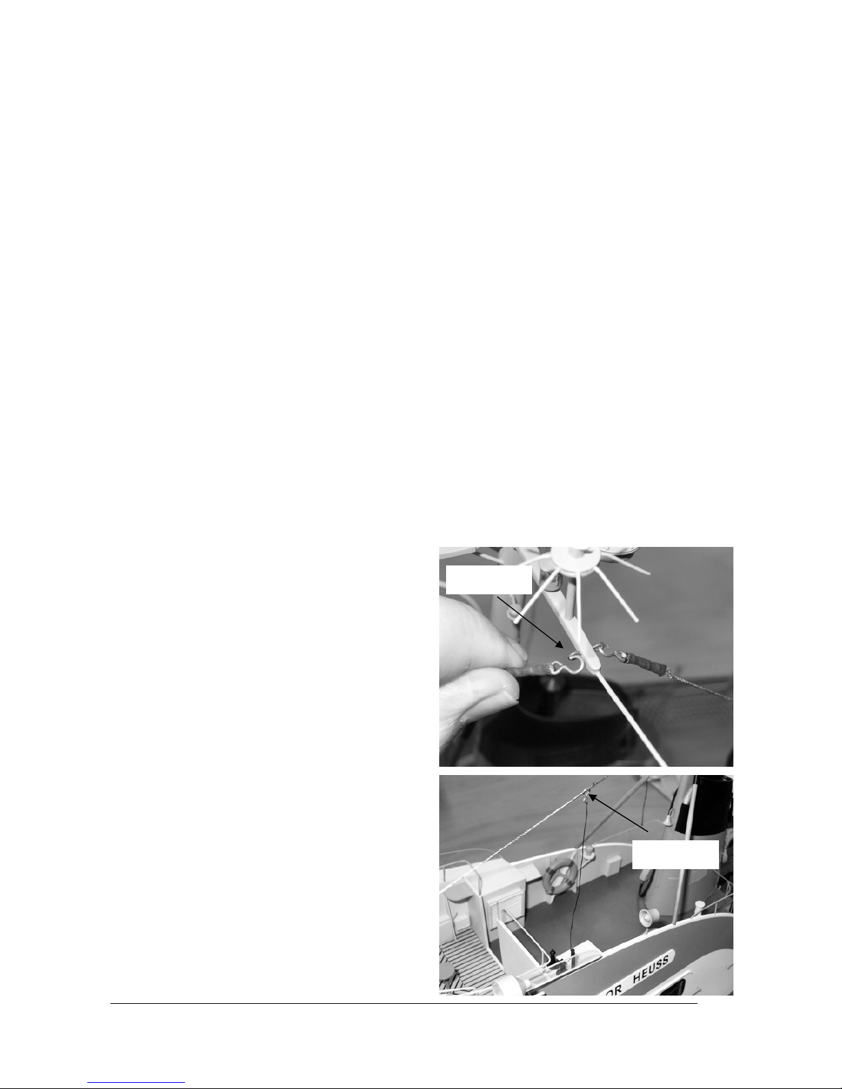
GRAUPNER GmbH & Co. KG D-73230 KIRCHHEIM/TECK GERMANY
Keine Haftung für Druckfehler. Technische Änderungen vorbehalten! Liability for printing errors excluded. We reserve the right to introduce modifications. Sous réserve de modifications! Nous ne sommes pas responsables d’éventuelles erreurs d’impression! #0059054 04/2008
24
• NOTE : Les moteurs électriques montés dans les modèles ne devront pas être jetés dans une poubelle
domestique lorsqu’ils seront usagés, ils devront être démontés et déposés dans un container destiné au
recyclage des appareils électriques et électroniques.
Entretien
• Nettoyez les modèles après chaque utilisation. Evacuez l’eau éventuellement infiltrée dans la coque. Si
de l’eau a pénétré dans les éléments R/C, laissez-les sécher et retournez-les au S.A.V. GRAUPNER
pour contrôle.
• Nettoyez les modèles et les éléments R/C uniquement avec des produits de nettoyage adaptés ; le
mieux est d’utiliser un chiffon doux. N’utilisez jamais de nettoyants chimiques, de solvants, d’essence,
d’alcool ou similaires.
• Lubrifiez régulièrement les arbres d’hélice et les paliers avec quelques gouttes d’huile spéciale (Par ex.
Réf. N°206). A la fin de chaque saison de navigation, les arbres d’hélice devront être démonté et à nouveau lubrifiés avec de la graisse spéciale (Par ex. Réf. N°570).
• Pour le Canot embarqué, il suffit de lubrifier les paliers du tube d’étambot après chaque navigation avec
quelques gouttes d’huile : un démontage de l’arbre d’hélice n’est ici pas nécessaire.
• Lubrifiez aussi les poulies sur lesquelles glisse le Canot embarqué, de même avec quelques gouttes
d’huile, afin qu’il puisse être facilement débarqué. Quelques gouttes d’huile également sur les paliers de
la trappe de poupe ne pourront pas la détériorer.
Instructions de montage
• Déballer soigneusement le modèle et le support du ba t eau.
• Retirer le Canot embarqué du baquet, le montage des éléments R/C sera décrit séparément dans les
instructions.
• Le raccordement des différents cordons sur le récepteur des deux modèles est représenté à titre
d’exemple sur le schéma de câblage. Les récepteurs conseillés (R700 pour le Croiseur et R600 light
pour le Canot embarqué) ont été représentés ici. Si d’autres types de récepteurs doivent être utilisés, il
faudra veiller à ce qu’aucune double occupation ne se fasse sur les deus récepteurs ; les modèles ne
pourraient pas ensuite naviguer séparément.
• Le modèle sera posé sur son support pour effectu er le s travaux suivants.
Le Croiseur
• Détacher soigneusement le fil de liaison pour
l’antenne du crochet. Détacher ensuite les quatre
fils d’antenne sur le mât (Voir les photos : Aushängen = Décrocher). La superstructure pourra maintenant être soulevée avec précaution.
• Souder un connecteur G2 sur le moteur central.
Soudez ensuite un conne cteur G2 sur les deux
moteurs extérieurs. Se référer au schéma de câblage sur la page 9, (Le Plus (+) est le fil rouge
clair, le Moins (-) est le fil noir). Veiller au sens de
rotation des moteurs, lorsque l’accu est connecté,
les hélices doivent tourner de façon à ce que le
modèle navigue en marche avant. NOTE : La polarité du système de connecteurs G2 est disposée de
façon à ce que l’ergot sur le corps en plastique soit
toujours le pôle Plus (rouge). Lorsque cette disposition est respectée, les accus et le régulateur de vitesse sont interchangeables entre eux et le système est sécurisé contre les inversions de polarité.
Pour pouvoir souder facilement le connecteur, il est
conseillé d’utiliser l’une des astuces suivantes.
afficher
afficher
Page 25

GRAUPNER GmbH & Co. KG D-73230 KIRCHHEIM/TECK GERMANY
Keine Haftung für Druckfehler. Technische Änderungen vorbehalten! Liability for printing errors excluded. We reserve the right to introduce modifications. Sous réserve de modifications! Nous ne sommes pas responsables d’éventuelles erreurs d’impression! #0059054 04/2008
25
• ASTUCE 1 : Démontez les moteurs. Pour cela,
dévissez les vis pointeau dans les accouplements
(seulement du côté des moteurs). Desserrer ensuite les vis des brides de fixation des moteurs (Ne
les desserrer pas complètement !) et retirez ensuite les moteurs. Le remontage se fera exactement dans l’ordre inverse.
• ASTUCE 2 : Avec ce qui est appelé une troisième
main, les connecteurs pourront être soudés directement dans le modèle.
• Contrôler le ferme blocage des autres vis dans les
accouplements (Voir la flèche sur la photo) et celui
des hélices, car elles auront pu éventuellement se
desserrer durant le transport. NOTE : Les hélices
sont en plastique métallisé et la vis pointeau devra
être serrée avec beaucoup de délicatesse, car autrement le taraudage dans l’hélice pourra être
détruit. La vis pointeau ne maintient pas l’hélice
seulement par une pression sur l’arbre, mais sur
un méplat que chaque arbre comporte. NOTE :
Bloquer éventuellement les vis pointeau dans les
accouplements d’arbre avec du freine filet, par ex.
UHU (Réf. N°952), car elles pourraient se
desserrer par les vibrations durant la navigation.
• Monter le palonnier à deux bras sur le servo des
gouvernails. Insérer les passes fils en caoutchouc
fournis avec le servo dans les pattes de celui-ci et
introduire dedans les œillets en laiton avec leur
collerette par de dessous. Placer le servo dans
l’ouverture à l’intérieur de la coque, percer les
avant trous pour les vis de fixation avec un foret de
Ø 1mm et fixer le servo avec les vis fournies parmi
ses accessoires. IMPORTANT : Veiller à ce que le
cordon du servo ne soit pas détérioré.
• Placer les gouvernails en ligne droite et connecter
la tringlerie de façon à ce que la cheville du clip de
sécurité corresponde exactement au trou de
connexion sur le palonnier avec le servo réglé au
neutre.
• Fixer le régulateur de vitesse et le récepteur latéra-
lement à la hauteur des moteurs à l’intérieur de la coque, avec de la bande à crampons.
• Relier le servo, le treuil de la trappe de poupe et les régulateurs au récepteur. NOTE : Les deus régula-
teurs seront reliés avec un cordon en V (Réf. N° 3936.11) ; avec l’utilisation d’un ensemble R/C à microordinateur, un mixeur libre dans l’émetteur pourra aussi être utilisé.
• Régler la trappe de poupe de façon à ce que le treuil ne soit plus sous charge sur la butée supérieure
centre moteur
l'extérieur moteur
clip
Page 26

GRAUPNER GmbH & Co. KG D-73230 KIRCHHEIM/TECK GERMANY
Keine Haftung für Druckfehler. Technische Änderungen vorbehalten! Liability for printing errors excluded. We reserve the right to introduce modifications. Sous réserve de modifications! Nous ne sommes pas responsables d’éventuelles erreurs d’impression! #0059054 04/2008
26
(Trappe fermée). Si cela ne peut pas être réglé sur
l’émetteur, desserrer la vis d’arrêt du tambour du
treuil et déplacer celui-ci sur le servo de façon à ce
que le treuil ne soit plus chargé, mais avec la
trappe de poupe fermée. a butée inférieure (Trappe
ouverte) devra être disposée de façon à ce que le
Canot embarqué puisse glisser facilement hors du
baquet. Une position optimale est montrée sur la
photo (prolongement en ligne droite de l’angle de la
trappe de poupe). Si cela ne peut pas être réglé sur
l’émetteur, marquer un repère sur le potentiomètre
de l’émetteur pour obtenir cette position le plus facilement possible. Si la trappe de poupe s’ouvre davantage vers le bas, cela n’est pas techniquement
critique, mais seulement peu réaliste. NOTE : Avec
les ensembles R/C conseillés, le potentiomètre devra être utilisé pour actionner la trappe de poupe,
avec un émetteur à micro-ordinateur comprenant
des réglages de course des servos, un inter pourra
aussi être utilisé. Mais un bouton de réglage sera
toujours préférable, car ici la trappe de pourra être
manœuvrée lentement d’une façon réaliste.
Fixer les cordons dans la coque avec des colliers
d’attache ou du ruban adhésif. NOTE : Ils ne doivent pas venir en contact avec les accouplements
d’arbre d’hélice.
• Disposez le fil d’antenne dé réception dans la co-
que ou niveau de l’ouverture du pont et le fixer
avec du ruban adhésif. IMPORTANT : Pour garantir une réception sûre, le fil d’antenne devra être
disposé le plus au dessus possible de la ligne de
flottaison et devra former un arc de cercle dans la
coque ! La coque en fibre de verre ne gêne que
très peu la réception. Une antenne fouet en fil
d’acier fin pourra aussi être installée sur initiative
personnelle ; le fil d’antenne du récepteur devra
alors être raccourci sur la longueur de l’antenne
fouet.
• Relier les deux régulateurs de vitesse avec le cor-
don répartiteur G2 (Réf. N°3068). Mettre en place
l’accu dans le modèle, le connecter au cordon parallèle et tester les fonctions de l’installation R/C.
L’accu devra être bien fixé pour la navigation afin
qu’il ne puisse pas se déplacer. Coller une bande à
crampons sur l’accu et la contre partie dans la coque, elles maintiendront ensuite fermement l‘accu
Page 27

GRAUPNER GmbH & Co. KG D-73230 KIRCHHEIM/TECK GERMANY
Keine Haftung für Druckfehler. Technische Änderungen vorbehalten! Liability for printing errors excluded. We reserve the right to introduce modifications. Sous réserve de modifications! Nous ne sommes pas responsables d’éventuelles erreurs d’impression! #0059054 04/2008
27
dans sa position. NOTE : Pour établir la bonne position du modèle sur l’eau, l’accu pourra être déplacé jusqu’à ce qu’il soit parallèle à la ligne de flottaison. NOTE : La position approximative de l’accu
dans la coque est visible sur la photo.
Le Canot embarqué
• Ouvrir le recouvrement central (celui avec la che-
minée en forme de champignon) sur le modèle ; il
est simplement fixé avec de la bande adhésive
double face. Les deux écoutilles pourront aussi
être entièrement retirées pour les travaux
d’entretien ; celles-ci sont également fixées avec
de la bande adhésive double face. Veiller à ce que
ces bandes soient encore suffisamment adhésives
pour la navigation ultérieure ; autrement il conviendra de les remplacer.
• Souder un connecteur BEC sur les fils
d’alimentation du moteur ; veillez absolument ici à
son sens de rotation. Avec la connexion de l’accu,
l’hélice doit tourner de façon à ce que le modèle
navigue en marche avant ; bien isoler les deux
points de soudure, ils ne doivent en aucun cas entrer en contact électrique.
• Monter un raccord de tringlerie sur le servo de
gouvernail à un seul bras. Pour cela, le deuxième
trou à partir du haut devra être repercé à Ø 2mm.
Coller ensuite le servo dans le support prévu dans
le modèle (Par ex. avec de la UHU Kraft, Réf.
N°1096). Introduire ensuite la tringlerie du gouvernail dans le raccord, placer le servo et le gouvernail en position milieu et bloquer la tringlerie dans
le raccord.
• Fixer ensuite le régulateur de vitesse et le récep-
teur dans le modèle avec de la bande à crampons.
Disposer le fil d’antenne de réception comme il a
été décrit pour le Croiseur. NOTE : Pour assurer
une meilleure réception, percer un trou de Ø 1mm
juste devant le pied du mât, faire passer le fil
d’antenne au travers et le fixer sur le mât avec du
ruban adhésif transparent. Faire une boucle au
pied du mât pour empêcher le fil de glisser (Voir la
photo).
• L’accu sera placé sous le Plicht inférieur et fixé
avec de la bande à crampons.
Page 28

GRAUPNER GmbH & Co. KG D-73230 KIRCHHEIM/TECK GERMANY
Keine Haftung für Druckfehler. Technische Änderungen vorbehalten! Liability for printing errors excluded. We reserve the right to introduce modifications. Sous réserve de modifications! Nous ne sommes pas responsables d’éventuelles erreurs d’impression! #0059054 04/2008
28
Schéma de câblage pour le Croiseur
Régulateur
moteur central
Vers le récepteur
3068
Moteur
Moteur
Connecteur G2 Connecteur G2
Moteur
Accu de propulsion
3068
Connecteur G2 Connecteur G2
Régulateur
moteurs extérieurs
3068
Cordon en V 3 93 6 .11
Récepteur
1
Cordon en V des régulateurs
Servos des gouvernails
7
2
6
Treuil pour trappe de poupe
Schéma de câblage pour le Canot embarqué
Vers le récepteur
Régulateur
Accu de propulsion
Moteur
Connecteur BEC
Connecteur BEC
Accu de propulsion
Régulateur
Récepteur
1
3
4
6
Fahrtregler
Ruderservo
Accu
Antenne
Page 29

GRAUPNER GmbH & Co. KG D-73230 KIRCHHEIM/TECK GERMANY
Keine Haftung für Druckfehler. Technische Änderungen vorbehalten! Liability for printing errors excluded. We reserve the right to introduce modifications. Sous réserve de modifications! Nous ne sommes pas responsables d’éventuelles erreurs d’impression! #0059054 04/2008
29
Lancement
Chargez tous les accus et testez les fonctions des deux modèles. Vérifiez si toutes les pièces enfichées sont
bien fixées. Vous pourrez alors procéder maintenant au lancement des modèles. Commencez par naviguer
lentement pour vous familiariser avec leur comportement. Le croiseur navigue relativement rapidement, il
possède une grande manoeuvrabilité et nécessité une longue course de ralentissement, c’est pourquoi il
devra être essayé sur un plan d’eau adapté. Naviguez au début en ne vous éloignant pas trop loin de la rive.
Testez la mise à l’eau du Canot embarqué à la proximité immédiate de la rive ; vous pourrez ainsi le récupérer à la main au cas où cela ne fonctionnerait pas comme prévu.
Nous vous souhaitons beaucoup de plaisir avec la navigation de votre modèle Theodor Heuss !
Pièces détachées
Réf. N°2013.6 Jeu d’hélices marines (seulement pour le Croiseur)
Accessoires nécessaires (Non fournis dans la livraison)
Accessoires conseillés (Croiseur)
Réf. N° Désignation
4714.41 Ensemble R. X -412, 41 MHz F
ou
4725.41 Ensemble R/C mc-12, 41 MHz, équipé en supplément avec le module proportionnel Réf. N°4170
2875 Régulateur de vitesse NAVY V40R (pour le moteur central)
2847 Régulateur de vitesse Power 60 (pour les moteurs extérieurs)
3936.11 Cordon en V, nécessaire avec l’utilisation de l’ensemble R.C mc-12
2581 Accu de propulsion Graupner 6N-8000 NiMH
2989 Système de connecteurs G2, pour le raccordement des régulateurs et de l’accu (2 pces nécessaires)
3068 Cordon répartiteur G2
Des cordons de rallonge de différentes longueurs, Réf. N°3935.XX seront nécessaires selon
l’emplacement des éléments R/C (Voir dans le catalogue général FS).
Accessoires conseillés (Canot embarqué)
Réf. N° Désignation
4054. 41 Micro récepteur R 600 FM 41 Light . NOTE : Avec un quartz de réception du même canal que celui de
l’émetteur.
5114 LOSE Servo C 141
2836.BEC Régulateur de vitesse PURPLE SX3R
7610.2 Accu de propulsion LiPo 650 7,4V/650mAh
3029.2 Cordon de raccordement moteur BEC
1182 Raccord de tringlerie
La commande se fait par l’ensemble R/C du Croiseur ou par un ensemble R/C séparé X-408 41 MHz, Réf. N°4729.41.
 Loading...