

GRAUPNER TAXI SPORT II Building Instructions
Order No.
9586
9586.M
Building Instructions
TAXI SPORT II
For two-stroke engines of around 7.46 cc capacity
and
electric motors
This model requires a four-function radio control system
GRAUPNER GmbH & Co. KG D-73230 KIRCHHEIM/TECK GERMANY
Modifications reserved. No liability for printing errors. 12/2010
Made in
Vietnam
1

Specification
Wingspan approx. 1600 mm
Fuselage length excl. spinner approx. 1190 mm
Wing area approx. 39.54 dm²
Tailplane area approx. 9.0 dm²
Total surface area approx. 47.54 dm²
All-up weight according to fittings approx. 2500 g
Longitudinal dihedral approx. 0.5 °
Downthrust and sidethrust built-in as standard
Caution: this model is not a toy!
If you are a beginner to this type of powered model, please ask an experienced
model flyer for help and support. If you attempt to operate the aeroplane without
knowing what you are doing, you could easily injure yourself or somebody else.
Please keep your safety and well-being in mind at all times.
Important: before you start construction
Even if you have already built a large number of RC models please read right through
these instructions and check that all the kit components are actually present. We
have taken great trouble to keep construction as simple as possible, without making
any compromises in the area of safety.
Check that the radio control system works correctly and at full range before every
flight: switch on the transmitter and the receiving system, and extend the transmitter
aerial to its full length; walk away from the model, and check that all the control
surfaces work smoothly and immediately at an appropriate distance; check also that
they deflect in the correct “sense” in relation to the stick movements.
If you are a relative beginner to this type of model flying, we recommend that you
enlist an experienced model pilot to help you check and test-fly the model.
RC system components and the control surface linkages must be installed at the
appropriate stage of construction, as it may be very difficult or even impossible to fit
them later.
When you are buying a radio control system it is important to ensure that the
transmitter and receiving system are designed for use with model aircraft, and are
approved by your national Post Office approvals authority. All RC units should
possess an FTZ series approval number.
Please remember that other radio systems and radio-frequency apparatus are also
permitted to operate in the frequency ranges used by model radio control equipment,
and there is no guarantee that your system will not suffer interference caused by
such apparatus.
Depending on where you operate the model, you may need to purchase a licence to
operate a radio control system for model aircraft on the approved channels in the 35
MHz band.
If you are not sure whether this applies to you, contact your nearest Post Office
Telecommunications office. Your local model shop will also have this information.
Note regarding the film covering
Minor creases or bubbles may develop in the film covering due to major fluctuations
in weather conditions (temperature, humidity etc.); in rare cases you may even find a
slight warp in a component. These minor faults are in the nature of film-covered builtup wooden structures, and can easily be corrected using a heat gun, as commonly
used for modelling.
2
Creases: Blow warm air over the area and rub down with a soft cloth.
Wing warp: Hold the panel twisted gently in the opposite direction to the warp, and
apply warm air to remove the creases from the covering.
Caution! do not heat the film more than is absolutely necessary. If the air or the
iron is too hot, the film may melt and holes may be formed.
This aeroplane is highly pre-fabricated and can be built in a very short time.
However, the work which you have to carry out is important and must be done
carefully. The model will only be strong and fly well if you complete your tasks
competently - so please work slowly and accurately.
When self-tapping screws have to be screwed into wood, apply a little white
glue to prevent them shaking loose: just squirt white glue into the hole before
fitting the screw.
Additional accessories required
Power plant and accessories
Engine
Order No.
OS MAX 46 AX
7.45 cc
2701
OS MAX 46 LA
7.64 cc
1888
Propeller
Order No.
28 x 15 cm
1318.28.15
28 x 15 cm
1318.28.15
Silencer
Order No.
1809.33
or
1871.72
1885.33
or
1870.72
Electric motor and accessories
Electric motor
Order No.
COMPACT
Propeller
Order No.
Flight battery
Order No.
Speed controller
Order No.
1318.40.25 9733.3 7224
465 Z
7772
Radio control system
The RC system must feature at least four channels and four servos. The
transmitter should also include a servo reverse facility.
We particularly recommend mx-16 to mc-24 computer systems. The model is
designed for standard-sized servos, e.g. DES585 BB, Order No. 7930.
We recommend the following receiver battery: NH-800 RX, Order No. 7499.4, which
should be maintained carefully before and after each flying session. Please note that
3

batteries of this type do not reach full capacity until they have been charged and
discharged (cycled) several times.
You will need two suppressor filters, Order No. 1040, to connect the aileron servos to
the receiver, and two further extension leads, 100 mm and 180 mm long. For shock
protection the receiver and receiver battery should be packed in soft foam, e.g. foam
rubber, Order No. 1637.
Adhesives
White glue, e.g. UHU coll, Order No. 958.60
Cellulose cement, e.g. UHU hart, Order No. 534.35
Cyano-acrylate (“cyano”), e.g. Order No. 5822
Thread-lock fluid, e.g. Order No. 952
Accessories required for the glow engine version (not included)
Synthetic oil-based fuel, to suit engine
Fuel filter, e.g. Order No. 1650.1
Fuel tubing, e.g. Order No. 1643
Manual fuel pump, e.g. Order No. 1610
Glowplug battery with glow clip, e.g. Order No. 3253
Electric starter, e.g. Order No. 1628
Starter battery, e.g. Order No. 2592
Accessories required for the electric-powered version (see table)
See the main FS catalogue for details of battery chargers
Tools required (not included)
Set of cross-point screwdrivers, flat-nose pliers, side-cutters, balsa knife or razor
blade, set of twist drills, universal glowplug spanner, soldering iron.
Please don’t start assembling the model until you have checked the kit components
and the building instructions, and are familiar with the construction procedure. If you
are not happy with any component, kindly return it to your model shop without delay.
4
Assembling the TAXI SPORT II
The wing panels
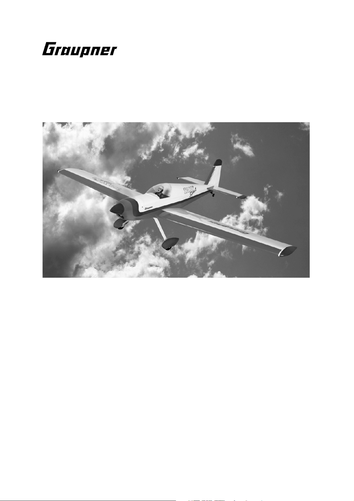
Use your fingertips to locate the opening in one wing for the aileron servo, and
remove the film over it using the tip of a hot soldering iron or a sharp balsa knife.
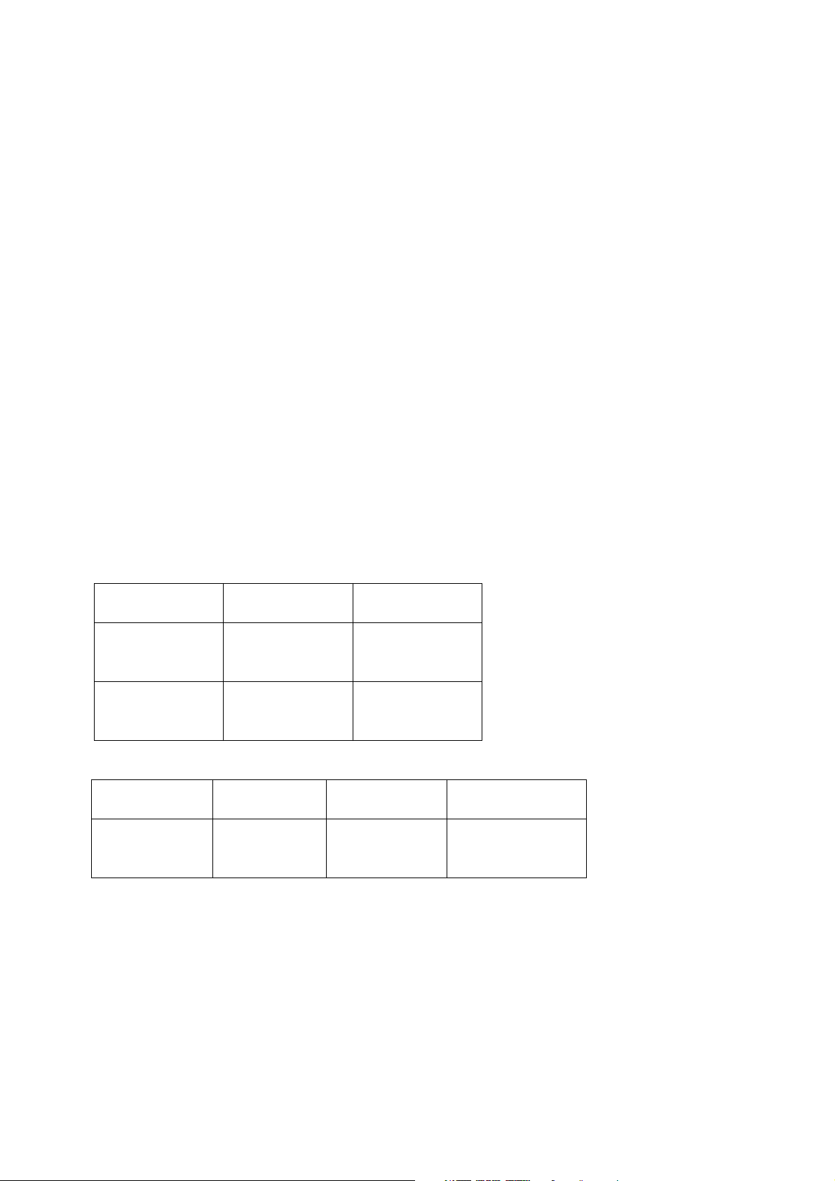
Press the rubber grommets into the servo mounting lugs, followed by the brass
tubular spacers, with the flange on the underside. The spacers are easier to fit if you
slip them onto a suitable screwdriver first.
Connect the appropriate extension cable to the servo lead, and fit a heat-shrink
sleeve or adhesive tape round the connectors to prevent them working loose.
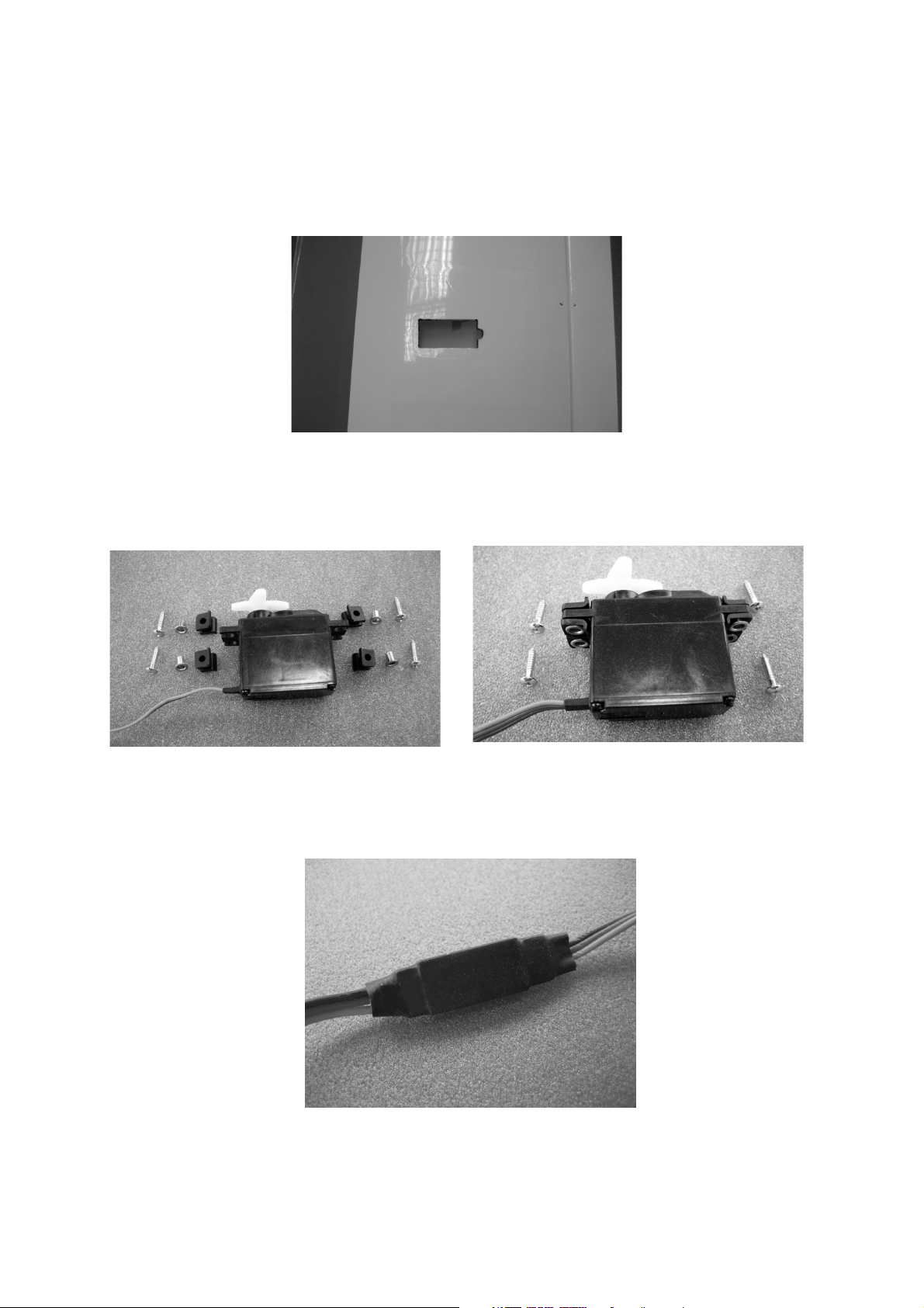
Route the servo lead through the wing from the servo recess. Fit the servo in the
opening as shown in the photo, drill 1.5 mm Ø pilot-holes for the retaining screws,
and secure it using the screws supplied in the servo accessory pack.
5
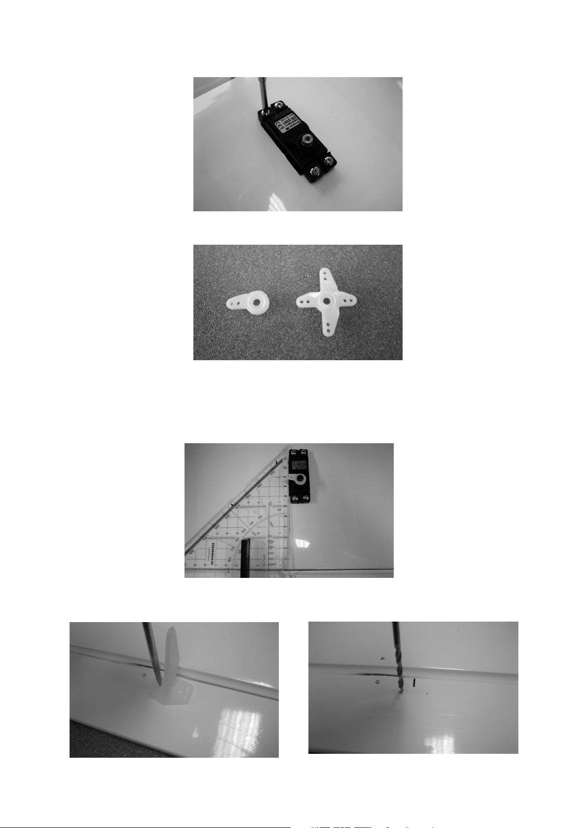
Cut down the servo output lever as shown in the photo below.
Fit the output arm on the servo output shaft, facing outward, i.e. towards the wingtip.
This arrangement means that the servos do not need to be reversed; this may be
useful if you are using a “simple” (non-computer) RC system.
Place a setsquare on the wing as shown in the photo, and mark the position of the
servo output arm linkage hole on the aileron, at right-angles to the control surface.
Mark the position of the horn holes on the aileron, and drill 2 mm Ø holes at the
marked points.
6

Fix the horn to the aileron using the pan-head screws and plastic spreader plate
supplied. Tighten the screws just to the point where the horn cannot shift - take care
not to over-tighten them.
Snip off excess screw length using side-cutters before filing back the cut ends flush
with the spreader plate.
Locate the M2 threaded pushrod (180 mm long) and fit a locknut and clevis on the
threaded end. Connect the clevis to the second hole from the outside of the aileron
horn. Use a felt-tip pen to mark the point where the pushrod crosses the linkage hole
in the servo output arm.
7
Use flat-nose pliers to bend the pushrod at right-angles at the marked point, and cut
off excess pushrod material using side-cutters, leaving the bent end around 7 mm
long. Connect the pushrod to the servo output arm and push the plastic keeper into
place to secure it. Repeat the whole procedure with the second aileron servo.
Installing the fin and tailplane
The covering film over the slots for the fin and tailplane should be removed using the
tip of a hot soldering iron. Please note that the iron should be a low-wattage type; the
heat should be just enough to melt the film.
Locate the slots with your fingertips, and mark their outlines with a felt-tip pen. Pierce
the film with the tip of the hot bit, and run it all round the edge of the opening until the
piece of film can be removed.
Repeat the procedure in order to open up the slots for the rudder and elevator
pushrods. Please note: two pushrods are used to actuate the elevators!
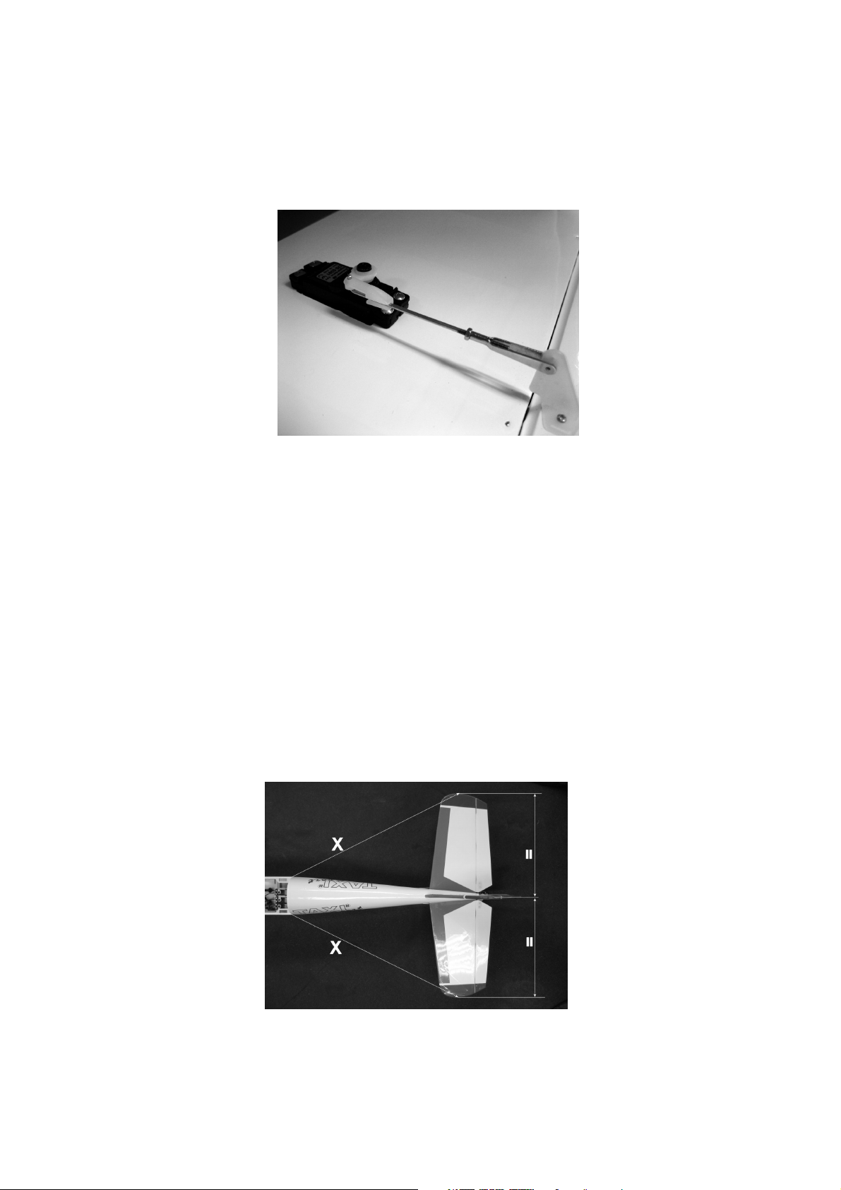
Fit the tailplane and fin in their respective slots. Position the tailplane in such a way
that it is at right-angles to the fuselage centreline when viewed from above, and
projects an equal distance on both sides, as shown in the diagram below.
8
 Loading...