

Page 1
EN
No. 2280
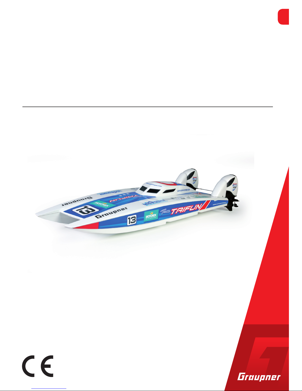
X-Cat model to be powered by 2 Power Seven Engines
Raceboat „Taifun“
Manual
Copyright © Graupner/SJ GmbH
Page 2

Page 3

3 / 14
2280_MP_V1
Inhaltsverzeichnis
For your notes .............................................................................4
Introduction ................................................................................. 5
Service Adresses .......................................................................5
Intended use ..............................................................................6
Package content ........................................................................ 6
Required components ..............................................................6
Declaration of conformity ........................................................ 7
Symbols explication ..................................................................8
Safety notes ................................................................................8
Assembling of the model .........................................................9
Apply the stickers: ..................................................................... 11
Partlist .........................................................................................12
Electric wiring ........................................................................... 13
Controlling the two motors ......................................................13
Telemetry .................................................................................. 13
Spareparts: ................................................................................13
Optionparts: ..............................................................................14
Page 4

For your notes
Page 5

5 / 14
2280_MP_V1
Introduction
Thank you for choosing a Graupner racing boat Typhoon. This
is extremely versatile.
Read these instructions carefully to ensure the proper functioning of the module and above all to safely control your models.
If any problems occur during operation, please refer to the
manual or ask your dealer or the Graupner Service Center.
Due to technical changes, the information in this manual is subject to change without notice. Inform yourself in regular intervals
on the Internet at www.graupner.de to stay up to date with the
product and the instructions.
This product complies with the legal national and European
requirements.
To maintain this condition and to ensure safe operation, you as a user
must read and follow these instructions and the safety instructions
before putting the product into operation!
NOTE
This manual is part of the product. It contains important instructions
for commissioning and handling. Therefore, save the instructions for
reading and give them to third parties when the product is distributed.
Service Adresses
Graupner-USA
3941 Park Dr Suite 20-571,
El Dorado Hills, CA. 95762
US
Servicehotline
(+001) 855-572-4746
service@graupnerusa.com
Graupner UK A.Brimingham@graupner.co.uk
Graupner in the Internet You can find all adresses on our webside www.graupner.com
Page 6

6 / 14
2280_MP_V1
Intended use
The model is controlled by 2 remote control sticks and is intended
for use only as a battery or battery-operated radio-controlled
models, otherwise operation is not permitted. No warranty or liability is accepted for any improper use.
Read the entire instructions carefully before connecting and using
the module.
Graupner / SJ is constantly working on the further development of
all products; We must therefore reserve the right to change the
scope of delivery in terms of form, technology and equipment.
target group
The product is not a toy. It is not suitable for children under 14
years. Installation and operation may only be carried out by experienced modelers. If you do not have sufficient knowledge of how to
handle remote-controlled models, contact an experienced modeler
or model-making club.
Package content
hull fiberglass
canopy fiberglass
2 motorhoods fiberglass
linkages for Power Seven Engines
Servomount Laserparts from wood
3 pcs. Decale Sheet
Manual
Required components
2x Outboard Engines„Power Seven“ No.1996
1x Propeller left No.1996.1
1x Propeller right No.1996.2
2x Inline Motor No.6646
2x watercooling No.6645.1
2x ESC No.33770.D35
1x rudderservo No.7951
2x Battery No.78145.3
1x Transmitter S1002.PRO.77.DE (more please visit www.graup-
ner.com)
Page 7

7 / 14
2280_MP_V1
Declaration of conformity
No. 2280 Raceboat Taifun
Graupner/SJ declares that the product is conform to CE norms
Technichal Data
Raceboat Taifun
Battery recommendation 2 x 2S oder 2 x 3S Lipo
meassures 900 x 285 x 170 mm with Power
Seven engines
Weight 3.000g
Speed depending on motors up to 70
km/h
required channels 2 (bzw. 1x Mixchannel or Y-cable)
NOTE
You will find the procedure of the mixing channel in the manual Part
2 of the transmitter.
function description
With the racing boat typhoon you have a thoroughbred Rennkatam
aran at the start. The geometry of the hull gives the model extremely good handling on the water including sharp turns.
Both recommended outboards are connected via a linkage and controlled with only one strong servo.
The fuselage, hood and hood are laminated from laminated fiberglass and are dyed white and trimmed to install the RC components.
Two inline engines No.6645 to 6649 provide different speeds depending on the ability and experience of the rider.
It is essential to operate the motors together with the
water cooling system No.6645.1 so that they do not overheat during operation and are damaged.
For the connection of the ESC`s there are two ways:
1. Both controllers on channel 1 are operated via Y cable No.S8187.
(First of all the controllers have to be taught in individually on the
control stick)
2. Operate the controller via mixer on the remote control. To do
this, the second controller is plugged into channel 6 and assigned
via the free mixers. Only one controller may supply the receiver
with BEC. For the second pull the red wire on the receiver cable!
Insert the telemetry cable from the BEC control to channel 5 (on the
GR-12).
Page 8

8 / 14
Symbols explication
!
Always observe the information marked with this warning picto-
gram. Especially those which are additionally marked by CAUTION
or WARNING. The signal word WARNING alerts you to possible serious injuries, the signal word CAUTION for possible minor injuries.
Note warns you of possible malfunctions.
Attention warns you about possible property damage.
Safety notes
!
These safety instructions are not only for your own safety
and the safety of others, but also for the protection of the
product. Therefore, read this chapter carefully before
using the product!
Do not leave the packing material careless, this could be a dangerous toy for children.
Persons, including children, who due to their physical, sensory
or mental capabilities or inexperience or ignorance are unable to
operate the transmitter safely, may not use the transmitter
without supervision or instruction by a responsible person.
The operation and operation of remote-controlled models must
be learned! If you have never steered such a model, be very
careful and familiarize yourself with the model‘s responses to the
remote commands. Always act responsibly. It also means that
you have a liability insurance for your own protection.
Protect all devices from dust, dirt and moisture. Never expose it
to vibration, excessive heat or cold. Remote control operation
may only be carried out at „normal“ outdoor temperatures, ie.
H. in a range of -10 ° C to +55 ° C. The racing boat Typhoon
was developed for use in model making and may be used according to its intended use only there.
Please note that the model may only be operated within the specified limits (see technical data).
Check the correct operation of the model before each use.
Page 9

9 / 14
2280_MP_V1
Assembling of the model
138 mm
Middle
Teilesatz 4
The fiberglass parts are all finished cropped. The wood laser parts
are glued together using the pictures (superglue No. 5821)
To install the servo base (4) in the fuselage, Stabilit Express no.
960.85. The position of the base is provided centrally in the fuselage. Rear cut-out hull hull to end socket is 138 mm.
Also with Stabilit Expres, the two aluminum tubes (7) for the rudder links are glued into the existing holes.
Drill 4 holes for attaching the
trims (3). Use screws (19)
Glue the aluminum tube (7)
into the fuselage. Overhang
on the outside about 2-3 mm
The rubber grommet (8) is
mounted on the tube and
fixed with a drop of superglue, as well on the linkage to
the outboard.
Glue the pre-glued servo
base in the middle of the
fuselage at a distance of 138
mm from the rear cut-out
edge. Prior to this, connect
both linkage systems as a
test. Align the aluminum
tubes so that they do not
touch the poles. Only then
glue and push on the rubber
grommets.
(8)
(6)
Page 10

10 / 14
2280_MP_V1
Use the hook and loop strap (20) to attach
the batteries.
The rubber sleeves (8) can be fixed with
some superglue or alternatively with cable
ties (optionally available under No. S8436)
Always place the antenna of the receiver
outwards and as far up as possible, as the
water surface can strongly reflect the radio
signal.
Seal the antenna bushing with some Fixogum No.575.
Align and glue the aluminum tubes (7)
slightly overhanging.
Thread the motor connection cables
through the socket on the fuselage. Then
close the maintenance opening of 20 mm
with the waterproof adhesive tape.
Secure all screws well with screw lock (No.
952)
On the engines the heat sink no. Mount
6645.1 and the nipples for feeding with silicone hose no. 1668.3 connect.
The discharge from the heat sink is in turn
out of the housing of the outboard motor.
To do this, use the lower recess on the rear
of the hood to guide the hose outwards.
Both outboards are connected via clevises
(5) and threaded rod (15). The outboards
themselves are screwed to the hull via the
8 screws (16).
2x Gestängeanschluß(9)
2x Sicherungsmutter (10)
No. 6645.1
Page 11

11 / 14
2280_MP_V1
Apply the stickers:
waterrestistant tape
No.531.19
The hood is closed after connecting the batteries with adhesive
tape No.531.19. It can also be installed the jumper No.21000.16
for better handling during the use of the model.
Page 12

12 / 14
2280_MP_V1
Position
number
Name pieces
1 hull fiberglass No.2280.7 1
2 canopy fiberglass No.2280.8 1
3 hoods fiberglass No.2280.9 2
4 Servomount wood No.2280.10 1 Set
5 Clevis, metal No. 3548 2
6 Threated shaft M2 x 500 mm 1
7 Aluminum tube 6 x 0,5 mm 2
8 rubber sealing, black No.3356 2
9 Threated rod 2- 3mm No. 3524 2
10 Safety nut M3 No. 712 2
11 grub Screw M3 x 3mm No. 107 2
12 ball joint rod connection 2
13 Sechskantmutter M2 2
14 rod connection 2
15 Threated shaft M2 x 200 mm 1
16 Tapping screw 2,9 x 13 mm 8
17 Foamboard 10 mm and plate 2
18 Tapping screw 2,2 x 13 mm 4
19 Tapping screw 2,2 x 6,5 mm 4
20 Velcro tape 25 cm 2
21 Decal set No.2280.14 1
22 Boatstand, wood No.2280.15 1
accessories:
water restitant tape No. 531.19
Fixogum No. 575
Power Seven Outboard Engine No.1996
Brushless Motor No.6646
Watercooling No.6645.1
Propeller left 29 mm No.1996.1
Propeller right 29 mm No. 1996.2
Silicon tube No.1668.3
Rudderservo DES 804 No.7950
ESC Brushless Control 70 No.33770.D35
Battery LiPo 3S/4.500Ah No. 78145.3
Partlist
Page 13

13 / 14
2280_MP_V1
Electric wiring
Controlling the two motors
Each brushless motor is powered by its own ESC. The connection to
the gas channel can be done in two ways:
1. The two controllers are connected to channel 1 via a Y cable
No.S8188.
2. The controllers are controlled by free mixers. To do this, set controller 1 to channel 1. Controller 2 on channel 6. For programming,
see the instructions for the transmitter.
Telemetry
The enormous advantage of our Graupner Hott system is the monitoring of all parameters by the specially developed sensors. The
telemetry cable of either controller is plugged into channel 5. With
it voltage, current and regulator temperature can be controlled
while driving. It makes sense to set warning thresholds. As an an
example:
Max. ESC temperature: 60 degrees Celcius
Max. Motor current: 70 A (No.33770.D35)
minimum Battery voltage at 3S: 10.5V
Should one of the values reach the threshold, the transmitter warns
acoustically and visually - before components are damaged.
Spareparts:
Hull No. 2280.7 Hoods No. 2280.9 Canopy No. 2280.8
Servomount No. 2280.10 Decal Set No. 2280.14
Boatstand No. 2280.15
Page 14

14 / 14
2280_MP_V1
Optionparts:
X8-E No.S1008.DE
mz-12 Pro No. S1002.Pro77DE 100 A ESC No. S3030
Power Seven No. 1996
Hood white No. 1996.7
Hood red No. 1996.5
Hood grey No. 1996.6
Battery No. 78145.3
Motor 4.300 KV No.6645
Watercooling No. 6645.1
Propeller 31 mm No. 1996. 3
Propeller 29 mm No.1996.2
Battery Plug No.21000.16
MOTOREX All Clear
No.95464
MOTOREX Dry Run
No.95464
MOTOREX Aqua Joker
No.95464
MOTOREX Extreme Power
No.95464
 Loading...