

Page 1
EN
AIO Copter Flight Control with copter firmware Q06
AIO Copter Flight Control
Manual
Copyright © Graupner/SJ GmbH
No. S1038 with 5V SBEC, No. S1038.SW with 12V SBEC
Page 2

2 / 36 3 / 36
S1038_Q06_V2.0sh_en S1038_Q06_V2.0sh_en
Table of content
Introduction ......................................................................................4
Service centre ...................................................................................4
Intended use ....................................................................................5
Target group ....................................................................................5
Package content ................................................................................5
Technical data ...................................................................................6
Symbol description ...........................................................................6
Safety notes ......................................................................................6
For your safety by handling the transmitter and the receiver .......7
For your safety by handling the batteries ......................................8
Installing the Graupner S1038 AIO FC .............................................9
Connecting the RC components of the copter ...............................9
Connection socket J9 “FPV transmitter” .....................................9
Connection socket J10 "Telemetry/Update/Waypoints" ............9
Connection socket J11 - J14 "RGB-LEDs" .....................................9
connection socket J28 or Pin lines "ESC" .....................................9
Connection socket M27 and M28 “CAM POWER“ ......................9
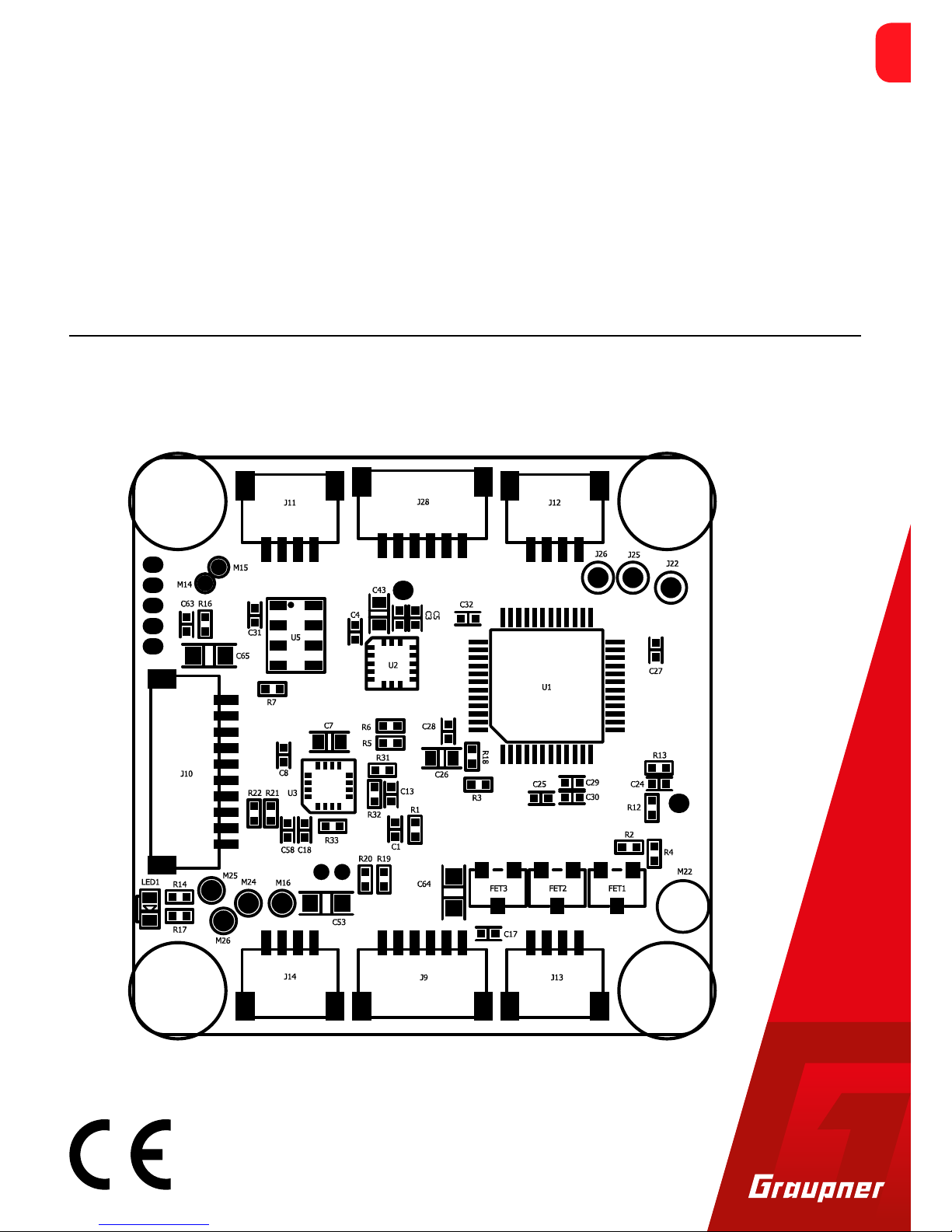
Top side of the Graupner S1038 AIO FC .......................................10
Bottom side of the Graupner S1038 AIO FC.................................11
Optional accessories ..................................................................11
Binding .............................................................................................12
Transmitter presettings ..................................................................13
Flight mode ...................................................................................13
Auto-flip function on channel 6 ....................................................15
Advancing the FPV transmit channel ...........................................15
"Telemetry" menu ..........................................................................17
SETTING & DATA VIEW ..................................................................17
Receiver display .........................................................................17
ROLL/NICK Display .....................................................................18
YAW Display ................................................................................20
MULTIC. AUTOPILOT ..................................................................20
BASIC Display ..............................................................................22
AXIS ASSIGNMENT .....................................................................28
Firmware update ............................................................................31
SIMPLIFIED DECLARATION OF CONFORMITY ................................34
Manufactured by ..........................................................................34
Notes on environmental protection ..............................................35
Care and maintenance ...................................................................35
Warranty certificate........................................................................35
Page 3
4 / 36 5 / 36
S1038_Q06_V2.0sh_en S1038_Q06_V2.0sh_en
Intended use
The Graupner S1038 AIO Flight Control should only be used for the
purpose specified by the manufacturer for operation of remote controlled UAVs and other unmanned RC-models. Any other type of use
is impermissible and may cause significant property damage and/or
personal injury. No warranty or liability is therefore offered for any
improper use not covered by these provisions.
In addition, it is explicitly pointed out that you must inform yourself
about the laws and regulations applicable at your respective starting
point before starting the remote control operation. Such conditions
may differ from state to state, but this must be followed in every
case.
Notes
• In general, it should forbidden to fly over airfields, factories,
nature reserves, built-up areas, etc.
• Where designated no-fly zones are located, and which in no way
affect them, it can be determined, for example, using the "AirMap" app.
Read through this entire manual before you attempt to install or use
the receiver.
Target group
The item is not a toy. It is not suitable for children under 14. The
installation and operation of the receiver must be performed by
experienced modellers. If you do not have sufficient knowledge
about dealing with radio-controlled models, please contact an experienced modeller or a model club.
Package content
• S1038 or S1038.SW AIO Copter Flight Control
• Manual
Introduction
Thank you very much for purchasing a S1038 Graupner AIO FC.
Read this manual carefully to achieve the best results with your HoTT
system and first of all to safely control your models. If you experience
any trouble during operation, take the instructions to help or ask
your dealer or Graupner Service Centre.
Due to technical changes, the information may be changed in this
manual without prior notice. Be always updated by checking periodically on our website, www.graupner.de to be always uptodate with
the products and firmwares.
This product complies with national and European legal requirements.
To maintain this condition and to ensure safe operation, you must
read and follow this user manual and all the safety notes before
using the product and you have to respect those notes also for future
use!
Note
This manual is part of that product. It contains important information concerning operation and handling. Keep these instructions for
future reference and give it to third person in case you gave the
product.
Service centre
Graupner Central Service
Graupner/SJ GmbH
Henriettenstraße 96
D-73230 Kirchheim/Teck
Servicehotline
(+49) (0)7021/722-130
Monday - Thursday:
9:15 am - 4:00 pm
Friday:
9:15 am - 1:00 pm
service@graupner.de
Graupner USA
3941 Park Dr Suite 20-571
El Dorado Hills, CA 95762
Website: www.graupnerusa.com
Phone: +1 855-572-4746
Email:service@graupnerusa.com
Graupner in Internet For the service centers outside Germany please refer to our web site
www.graupner.de.
Page 4
6 / 36 7 / 36
S1038_Q06_V2.0sh_en S1038_Q06_V2.0sh_en
Technical data
Antenna
1x 145 mm,
of which the last 30 mm active
Operating voltage 7.4 ... 15,2 V
Frequency range 2400 ... 2483.5 MHz
Modulation 2.4 GHz FHSS
Current consumption approx.
70 mA
Temperature range -15 … +70°C
Dimensions approx. 36 x 36 x 10 mm
Weight approx. 9 g
Symbol description
Always observe the information indicated by these warning signs.
Particularly those which are additionally marked with the words
CAUTION or WARNING.
!
The signal word WARNING indicates the potential for serious injury,
the signal word CAUTION indicates possibility of lighter injuries.
The signal word Note indicates potential malfunctions.
Attention indicates potential damages to objects.
Safety notes
!
These safety instructions are intended not only to protect the product, but also for your own and other people’s safety. Therefore please
read this section very carefully before using the product!
• Do not leave the packaging material lying around, this could be a
dangerous toy for children.
• Persons, including children, with reduced physical, sensory or
mental capabilities, or lack of experience or knowledge, or not
capable to use safely the receiver must not use the receiver without supervision or instruction by a responsible person.
• Operation and use of radio-controlled models needs to be learnt!
If you have never driven such a model, then start extra carefully
and make sure to be familiar with the reactions of the model to
the remote control commands. Proceed responsibly.
• First, always perform a range and function test on the ground (to
do so, hold your model tight), before you use your model. Repeat
the test with running motor and with short throttle bursts.
• Only use the components and spare parts that we recommend.
Always use matching, original Graupner plug-in connections of
the same design and material.
• Make sure that all of the plug-in connections are tight. When disconnecting the plug-in connections, do not pull the cables.
• Protect the AIO FC from dust, dirt, moisture and foreign parts. Do
not expose it to vibrations or to extreme heath or cold. The models may only be operated remotely in normal outside temperatures such as from -10°C to +55°C.
• Always use all your HoTT components only with the latest firmware version.
• If you have questions which cannot be answered by the operating manual, please contact us or another expert in the field.
For your safety by handling the transmitter and the receiver
!
WARNING
Also while programming the transmitter, make sure that a connected motor cannot accidentally start. Disconnect the fuel supply or drive battery beforehand.
!
CAUTION
Avoid every kind of short-circuit in all sockets of the transmitter!
Risk of fire! Use only the suitable connectors. In no case the electronic component of the transmitter or of the receiver may be
changed or modified. Due to licensing reasons, any reconstruction
and/or modification of the product is prohibited.
Note
During transport protect the model and the transmitter from damages.
Page 5

8 / 36 9 / 36
S1038_Q06_V2.0sh_en S1038_Q06_V2.0sh_en
For your safety by handling the batteries
!
CAUTION
• Protect the batteries from dust, dirt, moisture, heat and vibrations. Only use in dry locations.
• Do not use any damaged battery.
• Batteries may not be heated, burned, short-circuited.
• If handled improperly, there is a danger of fire, explosion, irritation and burns.
• Leaked electrolyte is caustic and should not be touched or
come into contact with your eyes. In case of emergency, rinse
with a large quantity of water and consult a Med. Doctor.
• Stock the batteries in dry and fresh conditions.
• Dispose of the battery in the proper disposal centers.
Installing the Graupner S1038 AIO FC
The Graupner S1038 AIO FC must be mounted with its lower surface
parallel to the chassis using the rubber buffers and M3 screws.
The Graupner S1038 AIO FC must be protected against dust, splash
water, etc. in the model. But do not pack your AIO FC too airtight so
that it does not overheat during operation.
The cables may not be wound around antenna or run next to it. Make
sure that the cables cannot shift to lie directly adjacent to antenna
during flight.
In the case of carbon fibre chassis, at least the last 35 mm of the
antennas shall be routed outside.
Connecting the RC components of the copter
Insert the connection cable of the ESCs of the copter, which must be
connected to the receiver, with the black or brown cable upwards
into the connector strip of the receiver, as shown in the illustration
on the left. The polarity of the plug-in system cannot be reversed. Do
not apply force. The servo connections of the Graupner-HoTT
receiver are numbered. Only use speed controllers that are multi-
shot capable to connect the motors.
Connection socket J9 “FPV transmitter”
If necessary, the FPV transmitter # 16570.123 is connected to the
socket labelled “J9”. For S1038.SW Voltage reduction 12V to 5V PDB
#8474 is needed.
Connection socket J10 "Telemetry/Update/Waypoints"
Connector J10 “Telemetry / Update / Waypoints”
If required, the optional GPS module, order no. 33602 connected. In
addition, receiver updates are performed through this jack.
The Smart Audio connector can be used to connect an FPV video
transmitter with the Smart Audio function. If required, the power
supply of the video transmitter can be made via the 5V / .SW 12V
connection and GND.
With the help of the adapter cable S1038.2 software updates or waypoints can be loaded. Optionally, a receiver can be connected to
SBUS to operate the flight control with an SBUS receiver.
The SBUS signal is detected automatically after switching on the
Flight control.
Connection socket J11 - J14 "RGB-LEDs"
If required, the optional RGB LED PCBs are connected to sockets
labelled "J11 - J14".
connection socket J28 or Pin lines "ESC"
The 4in1 ESC # 7242.4 is connected to the sockets labelled "J?". The
4in1 ESCs # S3087 or # S3088 are connected to the double row pin
headers J23 / 24.
Connection socket M27 and M28 “CAM POWER“
The FPV camera is connect to the sockets “M27” (GND) and “M28”
(5 V) (S1038.SW 12V).
Page 6
10 / 36 11 / 36
S1038_Q06_V2.0sh_en S1038_Q06_V2.0sh_en
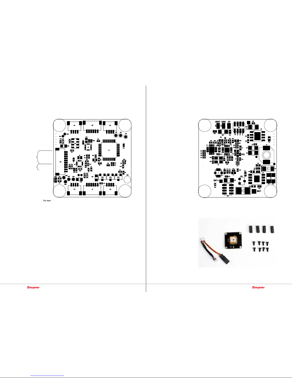
Top side of the Graupner S1038 AIO FC
RGB-LEDs
RGB-LEDs
B
G
R
+ 5V
/12V
B
G
R
+ 5V
/12V
RGB-LEDs
RGB-LEDs
B
G
R
+5V
/12V
B
G
R
+5V
/12V
CH8_TIM2_CH2
CH7_TIM2_CH1
CH6_TX3_TIM2_CH3
CH5_RX3_TIM2_CH4
GND
S1038 +5V,
S1038.SW 12V
FPV-TX
GND
+5V/ .SW +12V
USART1_TX
USART1_RX
I2C_SCL
I2C_SDA
GND
+5V/ .SW 12V
Telemetr./SBUS
SMART-AUDIO
+5V
+3V3
CURRENT
SENSE
USART2_RX
LED4
BAT+
GND
CURRENT SENSE
GND
PWM MOTOR 4
PWM MOTOR 3
PWM MOTOR 2
PWM MOTOR 1
GPS
S1038 5V
S1038.SW 12V
Bottom side of the Graupner S1038 AIO FC
BAT+
GND
CURRENT SENSE
S3087/S3088
PWM MOTOR1-4
GND
BAT+
S1038 5V
S1038.SW 12V
Optional accessories
GPS-Module 33602
Page 7

12 / 36 13 / 36
S1038_Q06_V2.0sh_en S1038_Q06_V2.0sh_en
Binding
To establish a connection with the transmitter, the Graupner HoTT
receiver must first be "bound" to at least one model memory in "its"
Graupner HoTT transmitter. This process is generally called "binding". However, the available methods to be used are not always the
same, so the following step-by-step instructions apply only to binding a HoTT AIO FC to any transmitter:
Binding step-by-step
• If the Graupner S1038 AIO FC is already bound to a specific trans-
mitter and this binding should be maintained, the transmitter
should ideally be switched on before the receiver. At the latest,
however, within approximately 15 seconds from the moment
when the receiver is switched on, the red LED of the receiver is
constantly on.
Attention
As soon as the LED starts to flash, the AIO FC is in bind mode.
From this point on there is the risk that the AIO FC unintentionally binds to a transmitter, which is casually in bind mode at the
same time, whereupon the model can run uncontrolled at any
time. The distance between transmitter and AIO FC should be at
least 0.5 m, otherwise the receiver of the AIO FC can be overdriven.
• If the Graupner S1038 AIO FC is unbound or it should be bound
to another transmitter or only the model memory has to be
changed than the previous one, proceed as follows:
1. Prepare the transmitter or model memory to be bound according to the instructions for binding.
2. Switch on the copter power supply.
3. The LED of the AIO FC lights constantly red.
4. Approximately 15 seconds after the AIO FC is switched on, its
red LED starts to flash, indicating that the AIO FC is now in
bind mode.
5. Start the transmitter-side binding according to the instructions of the transmitter.
6. If the red LED of the AIO FC goes out within about three seconds, the binding process has been completed successfully.
7. Your transmitter/AIO FC combination is ready for operation.
If the LED on the Graupner S1038 AIO FC remains still red, the
"binding" has failed. Change the positions of the associated
antennas and try the entire procedure again.
Transmitter presettings
Depending on the bandwidth of the model type selection of the
transmitter used, either the model type "Copter" or alternatively a
"Fixed-wing model" should be selected. Some of the current HoTT
transmitters are even shipped with preconfigured model memory.
According to the transmitter instructions, the appropriate control
mode and, if necessary, "motor front / rear" must be set. Usually
"backwards" so that the channel 1 indicator in the servo display indicates -100% in the "motor off" position of the "motor / pitch control
stick".
Flight mode
Flight mode has to be set to channel 5. To do this, according to the
transmitter instructions program a 3-way switch in the »Transmitter
setting« menu on channel 5 as follows on the next page:
Attitude mode
The stick movements acts directly proportionally to Roll and Nick. In
the attitude mode, the maximum inclination angle is limited to
approx. 50° at 100% of the stick travel.
The attitude mode is active as long as the bar of channel 5 is on the
left of +49 % in the »Servo display«.
(The 0 % shown on the left are based on the switch programming
above.)
Flight mode suggested for beginners.
Rate mode
In this mode, the rate is determined by the rash of the stick without
inclination limit. In this aerobatic mode rolls and loops are possible.
The rate mode is active as soon as the bar of channel 5 in the display
»Servo Display« is +50% or higher.
(The +100% shown on the left are based on the switch programming
above.)
Not suitable for beginners.
Note
The third switch position is required for the autopilot mode described
below and it is available only after the connection of the optional
GPS module No. 33602.
1
3
5
7
+
0%
0%
9
11
0%
0%
2
4
6
8
+
0%
0%
0%
0%
10
12
0%
0%
0%
0%
I5
I6
I7
+
trv
+100%
+100%
+100%
+100%
+100%
+100%
I8 +100%
+100%
free
free
free
SW4/5
I9
+100%
+100%
free
1
3
5
7
+
0%
0%
9
11
0%
2
4
6
8
+
0%
0%
0%
0%
10
12
0%
0%
0%
0%
+100%
I5
I6
I7
+
trv
+100%
+100%
+100%
+100%
+100%
+100%
I8 +100%
+100%
free
free
free
SW4/5
I9
+100%
+100%
free
Page 8

14 / 36 15 / 36
S1038_Q06_V2.0sh_en S1038_Q06_V2.0sh_en
Fail-Safe settings
FAIL SAFE
Pos
Hold
1 2 34567 8
Delay 0.25s STO
We recommend to set Channel 1 and Channel 5 to "Pos" according
to the transmitter instructions and to put the pitch control stick in
the motor OFF position before storing the fail-safe settings and to
set the attitude / rate mode switch to the "Attitude mode" position
so that the attitude mode is active in fail-safe situations and the
motors stop. When using the # S1038 AIO FC together with the
optional GPS-module # 33602, it is recommended to set C1 on Hold
and C5 and 6 on Pos, in the Come back home position, so that the
copter will fly back to the starting position if there is a loss of signal.
Note
Please note that when the signal is received again, the set mode will
become active again and the pilot will have to take again the control.
Throttle Cut
raised min
timer
+6%
4:00
cut off
Race timer
–100% +150%
1
yes
1
=
For safety reasons, a motor stop switch must always be programmed
on the transmitter side according to the transmitter instructions.
Only when this is placed into the appropriate position, an undesired
start of the motors is reliably prevented.
But in order to be able to switch off the motors also in the Acro 3D
mode, another mixer has to be programmed. Namely, if the copter
is operated in the acro 3D mode with the rate mode enabled, the
motor stop function would not shut off the motors, but set them to
"full power backwards". To prevent this, the mixer must be programmed in such a way that switching the motor stop switch to the
motor OFF position also switches to the attitude mode, in which the
stop of all motors is ensured.
Programming step-by-step
1. Program a linear mixer of "S => 5" according to the transmitter
instructions.
2. Assign to this mixer the same switch with the same switching
direction, which switches to the attitude mode.
3. Change to the setting page of the mixer.
4. Set the "travel" symmetrically to +100%.
5. Change to the line "Offset".
6. Now either set the offset value manually to +100% or set the
motor stop switch to "motor ON" and then push the ENT key. In
both cases, however, the adjacent picture must arise.
fro
M1
M2
M3
S
5
??
??
M4
M5
??
??
??
??
??
??
1
=
to
L.MIX1
trv +100%+100%
offs
SEL
STO
S 5
+100%
Auto-flip function on channel 6
If the copter is in attitude mode, the automatic flip function can easily trigger a flip of the copter.
The auto-flip function is activated via a key switch assigned to channel 6. This has to be programmed on channel 6 in the "Control setting" menu of the transmitter and then, with the button held down,
the asymmetrical travel must be set to +125%.
If this button is pressed, the servo position of channel 6 exceeds the
value of 111% and the autoflip function is thus "armed" for 5 seconds. As soon as the roll or pitch control stick is moved over more
than 50% of the stick travel within this time, the copter will automatically flip in that direction.
Note
After the flip, position deviations in the range <10 ° are possible.
Advancing the FPV transmit channel
I5
I6
I7
+
trv
+100%
+100%
+100%
+100%
+100%
I8 +100%
+100%
free
free
SW6/7
+100%
I9
+100% +100%
free
SW4/5
If the Attitude mode and the motor stop function are active, with
each switching pulse of +100% on channel 6, the transmission channel of the FPV transmitter can be switched in rotation.
Only with the optional GPS module No. 33602
Autopilot mode
The combination of a control signal of -100 % on channel 5 and 0 %
on channel 6 switches to autopilot mode. Neutral stick position
means to hold GPS position and altitude.
If you start in autopilot mode, the height is maintained at the middle
of the stick (0%).
If you start in Rate or Attitude mode and then switch to the autopilot mode, the throttle position when switching the mode is the stick
position at which the altitude is maintained.
When starting in autopilot mode with a throttle position above the
center of the stick (0%), the copter automatically raises to a altitude
of approx. 1m so that it can hold the position.In autopilot mode, an
electronic grid at 500 m distance and the set max. altitude active.
When the limits are reached, a corresponding warning message is
transmitted to the transmitter.
• An additional value higher as +50 % on Channel 7 switches to the
“Carefree Autopilot mode“.
Come back home mode
The combination of a control signal of -100 % on channel 5 and -100 %
on channel 6 switches to come back home to the start point mode.
I5
I6
I7
+
trv
+100%
+100%
+100%
+100%
+100%
I8
+100%
+100%
free
free
SW6/7
+125%
I9
+100% +100%
free
SW4/5
1
3
5
7
+
0%
0%
9
11
0%
2
4
6
8
+
0%
0%
0%
0%
10
12
0%
0%
0%
0%
–100%
I5
I6
I7
+
trv
+100%
+100%
+100%
+100%
+100%
I8 +100%
+100%
free
free
SW6/7
+100%
I9
+100% +100%
free
SW4/5
Page 9

16 / 36 17 / 36
S1038_Q06_V2.0sh_en S1038_Q06_V2.0sh_en
Departure from previously programmed waypoints
The combination of a control signal of -100 % on channel 5 and +100 %
on channel 6 switches to departure from previously programmed
waypoints mode.
To create the waypoints you will need:
• A suitable mobile phone with Android operating system.
• The app “GraupnerSJHoTTViewer2” on the mobile phone.
For transfer to the Kopter you will need:
• “micro USB OTG to micro USB cable”, No. 33002.OTG0M5
• Update adapter, No. S8500
• Update cable, No. 7168.S
Notes
• When the GPS is connected, the copter only allows the motors
to be switched on if 6 GPS satellites or more are found.
• While searching for GPS satellites, an HD camera should be off.
If more than 8 satellites have been found, the HD camera can be
switched on. But then is to check if there still are more than 6
satellites in the GPS Copter telemetry display.
• The Autopilot and Come back home mode only work in the configuration of how the compass was calibrated (eg with HD camera on). If you change the airfield, the compass should be recalibrated.
• If the departure of the pre-programmed waypoints is interrupted and switched to “autopilot” mode, the copter will stop
at the point of interruption.
Carefree autopilot mode
The combination of a control signal of -100 % on channel 5, +0 % on
channel 6 and +100 % on channel 7 switches to the carefree control
mode.
In Carefree control mode, the flight direction is saved when activated, even if the Copter is then rotated by yaw command.
This facilitates the control of the copter in difficult visibility conditions.
The combination of a control signal of -100 % on channel 5, +0 % on
channel 6 and -100 % … +50 % on channel 7 switches to normal con-
trol mode.
• An additional value less than +50 % on Channel 7 switches to the
“Autopilot mode“.
1
3
5
7
+
0%
9
11
–100%
0%
2
4
6
8
+
0%
0%
0%
0%
10
12
0%
0%
0%
0%
+100%
I5
I6
I7
+
trv
+100%
+100%
+100%
+100%
+100%
I8 +100%
+100%
free
SW6/7
3
SW4/5
+100%
I9
+100%
+100%
free
"Telemetry" menu
SETTING & DATA VIEW
The basic handling of the "Telemetry" menu is described in the
respective transmitter instructions or the instructions of the SmartBox. By way of derogation, only in certain receivers the menu structure is summarized under the generic term "setting & data view".
These instructions also provide information on how to access this
menu. Change accordingly to the first setting page of the Graupner
S1038 AIO FC.
Notes
• The setting values shown in the following display illustrations
always show the standard values.
• Some of the menu items shown in the following display illustrations are only displayed if the optional GPS module No. 33602 is
connected.
Receiver display
LANGUAGE
RECEIVER Q.06
ALARM VOLT: 10.2V
ALARM TEMP: 70°C
Altitude max: 100m
LANGUAGE: english
Video Channel R3
Alarm Capac. 400mAh
VTX-Power 0
In the "Language" line you can set the display language in the receiver
menu.
The choices are: German, English, French, Italian, Spanish
ALARM VOLT
If the receiver voltage falls below the set value, a low-voltage warning is generated by the transmitter in the form of a "sound-declining
alarm tone" or the "receiver voltage" speech output message.
ALARM TEMP
If the receiver temperature exceeds the set temperature, a warning
is generated by the transmitter in the form of a "3-step sound-climbing alarm tone" or the "receiver temperature" speech output message.
Max. altitude
Note
This menu item is only visible if the optional GPS module, No. 33602,
is connected.
If the optional GPS module No. 33602 is connected, this line is visible and in the autopilot mode, the altitude is limited to the set altitude value.
If the copter exceeds the set max. height, the transmitter will warn
you with "max. height"or, by transmitters without speech output,
with a corresponding tone sequence.
Telemetry
SETTING & DATA VIEW
SENSOR
RF STATUS VIEW
VOICE TRIGGER
RX DATA ON
ALARM SETTING
Page 10

18 / 36 19 / 36
S1038_Q06_V2.0sh_en S1038_Q06_V2.0sh_en
Video channel
If the video transmitter # 16570.123 is connected to the connector
J9, then the video channel can be set via this menu item.
In addition to what mentioned above, when the motor stop function
is active, the video channel can be further switched by a 2 second
switching pulse of +100% on control channel 6.
If a Smart Audio compatible FPV video transmitter with smart audio
is connected to port USART2_RX, then the Raceband channel 1-8
channel can be set via this menu item.
VTX-Power
If a Smart Audio compatible FPV video transmitter V2 or later with
Smart Audio is connected to port USART2_RX, the transmission
power can be set via this menu item. However, the setting only
applies to the current battery and will not be saved. After disconnecting the power supply and reconnecting the power supply, the
transmission power 0 is automatically active again until it is set differently again.
ALARM Capac.
If the used battery capacity exceeds the set value, a warning message "Capacity" is output in the transmitter or a corresponding
sequence of tones by transmitters without voice output. In this case
you should return to the starting point or, if this is no longer possible, land safely.
ROLL/NICK Display
The control is based on the PID principle, where the "P" stands for
"proportional", the "I" for "integral" and the "D" for "digital". In short
...
... the deviation from the setpoint proportional to the manipulated
variable has an effect at the P value.
... the existing control deviation is continuously summed up at the I
value and then acts on the manipulated variable via the I value.
... the differential component only takes into account the speed of
the control deviation and then acts on the control accordingly via the
D component.
ROLL/NICK P
This parameter determines the tilting behaviour of the copter during
the maximum climb.
In order to prevent tilting at full climbing power in the end, this
parameter must be increased in steps of 5 until a medium-fast tilting
occurs. Subsequently, this value is to be adjusted in individual steps
until the tilting has disappeared.
MULTICOPTER RO/NI
ROLL/NICK D 50
DAMPING 10
ROLL FACTOR % 95
POWER2SENS. 100
ROLL/NICK P 30
R/N DYNAMIC 70
––ATTITUDE MODE––
ROLL/NICK I 40
AGILITY 3
––RATE MODE––
R/N RATE I 10
RATE 70
ROLL/NICK D
This parameter determines the tilting behaviour of the roll / pitch
function of the copter.
As described above, this parameter must be adjusted until the Multicopter engages exactly over Roll and Nick. A too high value leads to
very rapid oscillations.
DAMPING
The damping factor should be set as low as possible, but as high as
necessary, so that the PID control can operate optimally. To prevent
oscillations or tilting, the damping should be <30. To dampen motor
or prop vibration and prevent motor noise, higher values may be
needed. These can be adjusted at the beginning in steps of 10 and
then finer.
ROLL FACTOR %
Set the Roll setting as percent value of the overall gain. For symmetrical copters, the value should normally be left at 100. If, because of
its gravity centre, the Copter is more agile on the Roll axis than on
the Nick axis, then you can change here the roll factor. In the Graupner
ALPHA RACE 250 Q this value is set about 65%.
POWER 2SENS.
Very strong drives can lead to oscillating at full throttle. This parameter allows you to set a kind of gyro suppression. Higher values result
in an increased suppression towards full throttle.
R/N DYNAMIC
Higher dynamic values provide a more direct feel for the flight (3D
flight 50 ... 100), lower dynamic values for smoother flight recordings, rounder freestyle flying and races (30 ... 50).
Note
If a channel is selected in the “R / N DYNAMIC” line, but no encoder
is assigned to it on the transmitter side, the value in brackets is
specified.
–– ATTITUDE MODE ––
ROLL/NICK I
Set the I component of the Attitude mode. At too low values of Copter tilts slowly. If it stops after a roll or pitch command and “oscillates”, the value must be reduced.
AGILITY
This value determines how fast a change of position is made.
Page 11

20 / 36 21 / 36
S1038_Q06_V2.0sh_en S1038_Q06_V2.0sh_en
–– RATE MODE ––
R/N RATE I
Sets the I component of the rotation in rate mode. At too low values
of Copter tilts slowly. If it stops after a roll or pitch command and
“oscillates”, the value must be reduced.
RATE
This value sets the maximum potential rate in Rate mode.
YAW Display
The general comments on PID control in the description of the roll /
pitch display are also applicable here.
YAW P
The P factor is responsible for the snap to yaw. Higher values result
in a faster stop. At too high P-values the copter starts to “swing”. In
such cases, the value must be reduced again.
YAW I
The I-factor ensures constant rotations. Start with low values and
only increase them until the rotations are constant. Too high value
cause an oscillation when you stop. Eventually, the motors can start
rotating and thus cause unwanted rising.
YAW D
The D-factor affects the stopping behaviour in Yaw. In most Copters
a hard D action is necessary. The D component must be set as low
as possible, since it affects the whole system.
RATE
For beginners we recommend a rate of about 50. For racers and freestyle pilots we recommend a value between 50 and 70.
YAW DYNAMIC
Higher dynamic values provide a more direct feel for the flight (3D
flight 80 ... 100), lower dynamic values for smoother flight recordings, rounder freestyle flying and races (30 ... 80).
MULTIC. AUTOPILOT
Note
This Displaypage is only visible if the optional GPS module, No.
33602, is connected.
GPS
YES: GPS features enabled. Starting the engines from 6 satellites.
NO: GPS features autopilot, come home and waypoints are disabled.
In autopilot mode, the attitude mode with altitude control active.
There is no need to wait for the engines to start until satellites are
found.
ALT HOLD P
The altitude hold P value compensates the climb and descent rate
and must be adjusted so that it is compensated as well as possible.
The copter must under no circumstances swing around the desired
height, otherwise the value must be reduced.
MULTICOPTER YAW
YAW I 10
YAW D 10
RATE 70
YAW DYNAMIC 75
YAW P 40
MULTIC. AUTOPILOT
ALT HOLD P 30
ALT HOLD I 10
ALT HOLD D 10
ALT HOLD II 5
GPS YES
POS HOLD P 40
POS HOLD I 15
POS HOLD D 10
POS HOLD II 50
ALT COMING HOME 25
Page 12

22 / 36 23 / 36
S1038_Q06_V2.0sh_en S1038_Q06_V2.0sh_en
ALT HOLD I
The altitude hold I value compensates for the height difference and
must be set so that it is compensated as well as possible. The copter
must under no circumstances swing around the desired height, otherwise the value must be reduced.
ALT HOLD D
The altitude hold D value compensates the acceleration (wind gusts)
in the height direction and it must be adjusted so that it is compensated as well as possible.
ALT HOLD II
The altitude hold II value compensates for the time-integrated height
difference, so that the desired height is kept as good as possible. This
does not usually have to be adjusted.
POS HOLD P
MULTIC. AUTOPILOT
ALT HOLD P 30
ALT HOLD I 10
ALT HOLD D 10
ALT HOLD II 5
GPS YES
POS HOLD P 40
POS HOLD I 15
POS HOLD D 10
POS HOLD II 50
ALT COMING HOME 25
The POS HOLD P value compensates for the position speed and must
be set to compensate as well as possible. The copter must never circling or overshooting the GPS target position, otherwise the value
must be reduced.
POS HOLD I
The POS HOLD I value compensates for the position difference and
must be set to compensate as well as possible. Under no circumstances the copter should oscillate around the GPS target position,
otherwise the value must be reduced or the compass calibration and
voltage calibration have to be repeated.
POS HOLD D
The POS HOLD D value compensates the acceleration (wind gusts) of
the GOS position and it must be adjusted so that it is compensated
as well as possible.
POS HOLD II
Currently without effect.
The POS HOLD II value compensates for the distance difference integrated on time so that the position setpoint is kept as good as possible. This does not usually have to be adjusted.
ALT COMING HOME
Determines the return altitude at Coming Home in meters.
BASIC Display
TYPE
The "Type" line defines the basic configuration of the copter. The following selections are available:
QUADRO X QUADRO XI (invers)
1
2
3
4
1
2
3
4
QUADRO +
1
2
3
4
Connect the speed controllers of the motors to the receiver following the proper scheme. The represented motor direction is referred
to the copter seen from the top.
ESC
The 4in1 controllers No. S3087, S3088 and 7242.4 have a built-in
power shunt. For correct current indication, the current connection
of the 4in1 controller must be connected to the S1038 AIO FC and
the corresponding 4in1 controller must be selected.
CURRENT FACTOR
The current factor is set to 100 (%) by default. However, if the current display is not accurate enough, it can be adjusted in the range
of 75 ... 125%.
Note
If the current can not be measured directly, the current factor can
be readjusted as follows: charging capacity * 100 / consumed capacity.
ESC: factory setting Multishot8
ONESHOT, MULTISHOT8, MULTISHOT32 are faster communication
protocols between receiver and ESC. Please check which protocol
your ESC supports. It allows the commands to be passed much faster
to the controller. Thus, the engines respond faster to the commands
MULTICOPTER BASE
ESC S3088
MODE NORMAL
MINPOWER % 5
TYPE QUADRO XI
CURRENT FACTOR 100
COMPASS CALIBR No
FREESTYLE 1
VIBRATION FILTER 80
CURRENT CALIBR No
CALIBR. POSITION No
LOGGING 10
ESC MULTISHOT8
Page 13

24 / 36 25 / 36
S1038_Q06_V2.0sh_en S1038_Q06_V2.0sh_en
!
CAUTION
Since the power control operates differently in the rate mode, see
figure on the left, the motors may start rotating more or less when
switching from the attitude mode to the rate mode, depending on
the current position of the pitch stick. Therefore always mount the
propellers immediately before starting the flight operation and
start and land exclusively in "attitude mode".
During prolonged extreme aerobatics of the copter in Acro 3D
mode (e.g. , sequence> 1min), the receiver may lose its attitude
information and, as a result, the copter may move to an undesired
position when switching to attitude mode. In this situation, the
copter should be in the Rate mode and either it is left quiet for
about 30 seconds or it is landed for a short time, so that the
receiver can readjust the position information again.
Note
If the motors do not stop completely in the attitude mode, so that
the position control is still active and can also serve as a rescue
mode in an emergency, this can be remedied with the aid of a mixer:
Mixer programming step by step
1. Program a same-channel mixer "1 => 1" according to the transmitter instructions.
2. Assign to this mixer the same switch with the same switching
direction, which switches to the attitude mode.
3. Leave this switch in the ON position.
4. Change to the setting page of the mixer.
5. Change through "ASY" to the setting field of the "Travel" line.
6. Set the value in the active value field of the "Travel" line to -30%.
In the idle position of the throttle / pitch stick, the bar of channel
1 in the "servo display" should now be at about -66%.
MINPOWER %
MULTICOPTER BASE
ESC S3088
MODE NORMAL
MINPOWER % 5
TYPE QUADRO XI
CURRENT FACTOR 100
FREESTYLE 1
ESC MULTISHOT8
If the throttle / pitch control stick is moved past its stop on the idleside stopper of the copter speed controller, the motors will start to
run. The setting value of this option determines the minimum power
to be provided at the switch-on point so that the position control can
continue to operate in the Attitude mode and it can also serve as a
rescue mode in an emergency. But do not set a too high value here
in order not to restrict too much the control range of the speed controller.
The adjustment range is 5 ... 35%.
Vollgas positiv
Vollgas negativ
Min. Gas
linear bis Vollgas
Gasweg
Drehratenmodus
Gasweg
Lagemodus
linear
linear
Motor Min. Gas
L.MIX2
off
ASY
SYM
C1 C1
0%
trv –30% 0%
fro
zu
M1
M2
M3
S
5
C1
C1
M4
M5
??
??
??
??
??
??
1
=
to
3
=
MINIPOWER %
Travel Throle/Pitch control sck
of the receiver. The Motor Output Signal is now shorter, for oneshot
125μs-250μs, even faster with MULITISHOT with 5-25µs. MULTISHOT8 is the default. Faster protocols improve flight behavior, as
long as the ESC can process the protocol without errors.
MULTISHOT32 must not be used in 3D Mode, because most of the
ESCs could not handle this.
MODE
CONTROLLER SETTING
To initialize the controller, the signal of the motor / pitch control stick
of the transmitter is transmitted directly to the speed controller of
the copter.
Setting the speed controllers step-by-step
1. Remove rotors for safety reasons
2. Make sure that the transmitter-side pitch signal reaches ± 100%.
3. In the telemetry menu of the transmitter, change the value field
of the “MODE” line to “CONTROLLER SETTING” and confirm with
ENTER.
4. Switch off the copter or unplug the battery plug.
5. Switch off the motor stop function of the transmitter.
6. Move the pitch control stick of the transmitter to the full throttle
position.
7. Switch on the copter or connect the battery.
8. Wait for the confirmation melody or, if no sound is heard, alternatively switch on the motor stop function after approx. 15 seconds.
9. After approx. 15 additional seconds, check the function.
10. In the telemetry menu of the transmitter, reset the value field of
the “MODE” line to the original setting and confirm with ENTER.
11. Switch off the copter or unplug the battery plug.
12. If the motors do not start after completion of this process despite
active binding, the copter must be bound again.
NORMAL
This setting must be used for copters with speed controller without
reverse of the direction of rotation.
ACRO 3D
This setting is reserved for copters whose speed controllers are
equipped with direction reverse.
Note
For safety reason the "Type" and "Mode" changes take effect after
switching off and on again the receiver system.
Page 14

26 / 36 27 / 36
S1038_Q06_V2.0sh_en S1038_Q06_V2.0sh_en
Note
If a channel is selected in this line, but no control is assigned in the
transmitter or otherwise it influences its neutral position, the value
“50” in parenthesis is predefined.
COMPASS CALIBR
Note
This menu item is only visible after connecting the optional GPS
module, No. 33602.
After each change of the airfield the compass has to be recalibrated.
In contrast, the current calibration described below does not have
to be repeated every time.
Notes
• When using an HD camera, it must be turned on when calibrating the compass. Otherwise, the autopilot mode and the come
back home function only work when the HD camera is switched
off!
• If the autopilot and come back home function is used, the HD
camera may also have to be switched on, as its power requirement influences the compass calibration.
• Avoid calibrating the compass near magnetic fields, powered-on
cell phones, or other objects that may be interfering with the
natural magnetic field.
Compass calibration step by step
1. Bring the angle „ “ on the left edge of the display to the „COMPASS CALIBR.“ line.
2. Push the ENT key to activate the value field.
The value field is displayed inverted.
3. Change the value field to „Yes“.
4. Push again the ENT key.
The value field is again displayed as „normal“.
5. Slowly rotate the multicopter twice in a circle around all three
axes and then randomly in different directions until „NO“ appears
in the display.
2x
2x 2x
Otherwise the process has to be repeated.
MULTICOPTER BASE
MINPOWER % 5
COMPASS CALIBR No
FREESTYLE 1
VIBRATION FILTER 80
CURRENT CALIBR No
CALIBR. POSITION No
LOGGING 10
FREESTYLE
The setting basically serves to prevent the I-factor from generating
a vibration.
The higher the value, the more I-vibrations are prevented, but also
the straight-ahead flight is degraded. Values up to max. 20 recommended.
The adjustment range is from 1 ... 100
MIN = disabled
Alternatively, the effect on the I value can also be adjusted by the
transmitter. To do this, a rotary or slider control is assigned to one of
the control channels 5 ... 16 and the remaining settings are left at the
default values. In the value field of the "Freestyle" line, the corresponding channel is then merely to be selected instead of a fixed
value.
Note
If a channel is selected in this line, but no control is assigned in the
transmitter or otherwise it influences its neutral position, the value
"50" in parenthesis is predefined.
VIBRATION FILTER
MULTICOPTER BASE
ESC S3088
MODE NORMAL
MINPOWER % 5
CURRENT FACTOR 100
FREESTYLE 1
VIBRATION FILTER 80
ESC MULTISHOT8
If you hear , for example, “clicking” noises in the motors by widely
fluctuating speeds or vibrations during the flight, such as in low
throttle or under hover conditions, these vibrations can be filtered
out with the options “damping” and “vibration filter”. Preferably,
start with the “vibration filter”:
Configure vibration filter step-by-step
1. In the transmitter assign a rotary or slider to a free control channel, e.g. channel 8
2. Select this channel in the value field of the “VIBRATION FILTER”
line.
3. In flight, adjust the “VIBRATION FILTER” with the selected controller until the motor noises disappear or at least cannot be further
reduced and the rotor speeds are as constant as possible.
4. Leave the control in this position.
5. After landing, read out the set value found in the “VIBRATION FILTER” line of the telemetry menu and then set it manually in the
value field, see “67” in the two examples on the left.
6. If vibrations still occur during the flight at a different speed, the
filter may need to be adjusted slightly or even adjusted according
to gas.
Adjustment range: 100 … 1, MIN, (0)C5, (50)C6 … (50)C16
The usual adjustment range of the vibration filter is between “65”
with 4 ... 5 inch rotors and 80 with 3 inch rotors.
Extremely low values should be avoided as these will worsen the
flight behaviour.
MULTICOPTER BASE
ESC S3088
MODE NORMAL
MINPOWER % 5
CURRENT FACTOR 100
FREESTYLE 1
VIBRATION FIL(67)CH8
ESC MULTISHOT8
MULTICOPTER BASE
ESC S3088
MODE NORMAL
MINPOWER % 5
CURRENT FACTOR 100
FREESTYLE 1
VIBRATION FILTER 67
ESC MULTISHOT8
Page 15

28 / 36 29 / 36
S1038_Q06_V2.0sh_en S1038_Q06_V2.0sh_en
CURRENT CALIBR.
Notes
• This menu item is only visible after connecting the optional GPS
module, No. 33602.
• With active current calibration, the attitude control is inactive,
which is why this process must be done on the ground or with
appropriately secured copter.
• The current calibration should be done in calm wind conditions,
otherwise the current will fluctuate too much and make the calibration more difficult.
• The current calibration becomes most accurate when the nose
of the copter points either the west or east direction, because
then slight deviations can better detected.
• Furthermore, the suspension position must first be determined
and remembered before, if necessary, the propellers are
reversed and mounted vice versa, so that the copter is pressed
to the ground instead of lifting.
• During the current calibration, the copter must not move and no
other control sticks may be moved during the calibration except
for the throttle stick.
Current calibration step by step
1. Move the throttle / pitch control stick to the idle position and the
motor ON / OFF switch to the motor OFF position.
2. Bring the angle „
“ on the left edge of the display to the “CUR-
RENT CALIBR.” line.
3. Push the ENT key to activate the value field.
The value field is displayed inverted:
4. Change the value field to “Yes”.
5. Push again the ENT key.
The value field is again displayed as “normal”.
6. If “CURRENT CALIBR.” is displayed in the value field of the “CURRENT CALIBR.” line, the switch must be brought to the motor OFF
position if necessary.
7. If “Min” is displayed in the value field of the line CURRENT CALIBR, switch must be switched to the motor ON position.
8. If in the value field of the line “CURRENT CALIBR.” “hover” is displayed, the throttle / pitch control stick must be brought into the
hover position. If the display changes to Min, then please switch
the motors to the Mingas throttle position.
Note
If the copter has rotated by mistake or by a command during the
current calibration, the calibration must be repeated.
MULTICOPTER BASE
MINPOWER % 5
COMPASS CALIBR No
FREESTYLE 1
VIBRATION FILTER 80
CURRENT CALIBR No
CALIBR. POSITION No
LOGGING 10
CALIBR. POSITION
With this option, if necessary, the basic calibration of the acceleration sensors can be readjusted, so that the copter hovers with the
stick and trim to neutral, in attitude mode, precisely horizontally.
To recalibrate, place the copter on an absolutely horizontal surface
and then set the value field to "YES".
As soon as the calibration is completed, the display changes back to
"NO". To accept the calibration that has just been carried out in the
non-volatile memory of the receiver, it is essential to push or tap on
the ENT key.
LOGGING
Note
This menu item is only visible after connecting the optional GPS
module, No. 33602.
Logging 0 displays the Euler angles in the Copter telemetry display
and also allows the position display using the Graupner HoTT OSD #
33641 on the FPV screen or in the FPV video goggles.
10mAh I 0A
0:00 Dir: 0°
11.6V Alt: 0m
0km/h 0°
0 0m
C+00016 +00060 -00011
The default value “10” indicates the compass direction in degrees in
the bottom line of the Copterdisplays right of the “ ”, so that it can
be checked, for example after a recalibration of the compass. The
characters 2 … 14 before show raw values and the “C” at the beginning of the line stands for “Compasslogging”. In addition, this display
can be used to check the Power calibration: If the Copter is fixed to
the west or east, the degree indicator on the right may only change
slightly if the motors are off, or rotate driven by minimal power or
hover power. Otherwise, a calibration should be performed.
The other logging functions are exclusively intended for the service.
AXIS ASSIGNMENT
Note
The gyroscope calibration, required each time the copter is switched
on, takes place as soon as the copter or its receiver is absolutely
quiet. The motors will not start until the calibration is completed.
After approx. 3 seconds in the rest position, several beeps can be
heard from all motors. The number of beeps varies depending on
the speed controller used. These "wiggles" signal that initialisation
has been successful and that calibration is complete.
!
CAUTION
If the copter is used for long time (>1min) in Acro 3D mode the
receiver can loose its position information and the copter can
move itself out of control. In this case the copter should be left in
the rate mode and hover or land calmly for approx. 30 s, so that
the receiver can track the position again.
MULTICOPTER BASE
MINPOWER % 5
COMPASS CALIBR No
FREESTYLE 1
VIBRATION FILTER 80
CURRENT CALIBR No
CALIBR. POSITION No
LOGGING 10
Page 16

30 / 36 31 / 36
S1038_Q06_V2.0sh_en S1038_Q06_V2.0sh_en
In this display, the gyros and their effective direction are to be determined.
NEW SETUP
After selecting the line "do setup" and changing the value field to
"yes", assign the axes as follows:
Do setup step by step
1. Push or tap on the ENT key
"NO" is displayed inverted.
2. Change the value field to "YES".
3. Push or tap on the ENT key
4. At the transmitter briefly bring the roll control stick to the right
stop.
The display shows the roll axis inverted.
5. Tilt the copter more than 45 degrees to the right.
As soon as the detected axis with the required sign is displayed in
"normal" representation, the axis assignation is completed.
6. At the transmitter briefly bring the nick control stick to the front
stop.
The display shows the nick axis inverted.
7. Tilt the copter more than 45 degrees to the front.
As soon as the detected axis with the required sign is displayed in
"normal" representation, the axis assignation is completed.
8. At the transmitter briefly bring the yaw control stick to the right
stop.
9. Turn the copter clockwise by more than 45 degrees to the right.
As soon as the detected axis with the required sign is displayed in
"normal" representation, the axis assignation is completed.
The gyros and their operating directions have now been assigned.
Attention
To be on the safe side, the directions of action of the gyroscope settings must be checked.
Check step by step
1. Remove the rotors of the copter.
2. Use the pitch control stick to give approx. 25% "throttle".
All motors run at the same speed.
3. Switch to the attitude mode.
4. Tilt the copter forward.
The front motors must turn faster than back ones.
5. Tilt the copter to one side.
The motors of the side, the "hanging" side must turn faster than
those of the opposite, higher side.
GYRO ASSIGNMENT
do setup NO
ROLL +2
NICK +1
YAW –3
Firmware update
Firmware updates of the Graupner S1038 AIO FC are performed via
the J10 connector on its side, using a laptop or PC running Windows
7 ... 10. You will also need a USB interface, No. 7168.6, so as the
adapter lead, 7168.6S, which are available separately. Furthermore,
either the adapter cable No. 33602.1 included in the package of the
GPS module, No. 33602, or the optionally available adapter cable
No. S1038.2 are required.
The programs and files required can be found in the Download area
for the corresponding products at www.graupner.de.
One of the last two mentioned adapter cables must be connected to
the 7168.6S cable and this combination must then be connected to
the USB interface, No. 7168.6. The plug-in system is correspondingly
protected against reverse polarity. Never use force, the plugs should
click easily into place.
Insert the free end of one of the two adapter cables with the plug
side facing upwards into the socket of the Graupner S1038 AIO FC
marked “J10”. Under no circumstances you should use force here.
The update takes place via the program part “Slowflyer / Gyro
Receiver Downloads” of the program “Firmware_Upgrade_gr_Studio” available under “Links”. Please follow the notes of the software.
The further procedure is also described in detail in the manual contained in the data package. You can also download these from the
download page of the product at www.graupner.de.
7168.6
7168.S
33602.1
S1038.2
OR
+
Page 17

32 / 36 33 / 36
S1038_Q06_V2.0sh_en S1038_Q06_V2.0sh_en
Page 18

34 / 36 35 / 36
S1038_Q06_V2.0sh_en S1038_Q06_V2.0sh_en
‖ If this is not the case, the entire gyro assignment must be
repeated.
SIMPLIFIED DECLARATION OF CONFORMITY
Graupner/SJ hereby declares that the Graupner S1038 AIO FC com-
plies with the Directive 2014/53/EU.
The full text of the EU Declaration of Conformity is available at the
following Internet address: www.graupner.deNotes on environ-
mental protection
Manufactured by
Graupner Co., Ltd
Post Code: 14557
8th F, 202 Dong, Chunui Techno-Park II, 18, 198 Street
Bucheon-ro, Wonmi-Gu, Bucheon-Shi, Gyeonggi-do
South Korea
Notes on environmental protection
If this symbol is on the product, instructions for use or packaging, it
indicates that the product may not be disposed with normal household waste once it has reached the end of its service life. It must be
turned over to a recycling collection point for electric and electronic
apparatus.
Individual markings indicate which materials can be recycled. You
make an important contribution to protection of the environment by
utilizing facilities for reuse, material recycling or other means of
exploiting obsolete equipment.
Batteries must be removed from the unit and disposed of separately
at an appropriate collection point. Please inquire if necessary from
the local authority for the appropriate disposal site.
Care and maintenance
The product does not need any maintenance. Always protect it
against dust, dirt and moisture.
Clean the product only with a dry cloth (do not use detergent!) lightly
rub.
Warranty certificate
Graupner/SJ GmbH, Henriettenstrassee 96, 73230 Kirchheim/Teck
grants from the date of purchase of this product for a period of 24
months. The warranty applies only to the material or operational
defects already existing when you purchased the item. Damage due
to misuse, wear, overloading, incorrect accessories or improper handling are excluded from the guarantee. The legal rights and claims
are not affected by this guarantee.
Please check exactly defects before a claim or send the product,
because we have to ask you to pay shipping costs if the item is free
from defects.
These operating instruction are exclusively for information purposes
and are subject to change without prior notification. The current
version can be found on the Internet at www.graupner.de on the
relevant product page. In addition, the company Graupner/SJ has
no responsibility or liability for any errors or inaccuracies that may
appear in construction or operation manuals.
Not liable for printing errors.
P
Page 19

 Loading...