

Page 1
Copyright © Graupner/SJ GmbH
Part 2
Programming manual
Manual
No. S1006.PRO
12 channel HoTT 2,4 GHz transmitter
mz-24 Pro
Page 2
General operating instructions
Before use ................................................................ 3
Warning and advisory symbolsand their meaning ..... 3
Starting up the transmitter ....................................... 4
Operating the display .......................................... 6
Warnings ............................................................. 8
DSCsocket ....................................................... 10
Data socket ....................................................... 10
Ear phones port ................................................. 11
Card slot ............................................................ 11
Mini-USB connection ........................................ 12
Starting up the receiver .......................................... 14
Installation notices .................................................. 16
Safety and handling
instructions for Lith. Batteries ........................... 22
Definition of terms .................................................. 24
Control and switch assignment ............................... 26
Receiver configuration
Vehicles, boats and copters ............................... 30
Helicopter models .............................................. 31
Fixed-wing models ............................................. 32
Program description
Program description ............................................... 34
Base menu
Model selection ...................................................... 38
HoTT synchronization methods setting ............. 39
Model name ............................................................. 42
Manually programming the basic settings of a
new model .......................................................... 42
Entering the basic settings of a new model with
an assistant ........................................................ 44
Index
Model type ............................................................. 60
E.P.A ....................................................................... 62
REV/SUB ................................................................ 64
Throttle Cut ............................................................. 66
Transmitter setting .................................................. 68
Timers ..................................................................... 74
Fail Safe .................................................................. 80
Trim settings ............................................................ 82
Servo monitor ......................................................... 86
Base menu - Control/switch setting ....................... 90
Throttle limit function ......................................... 94
Transmitter output .................................................. 96
Telemetry ................................................................ 98
Announces ............................................................ 118
Function menu
Phase .................................................................... 120
D/R,EXP ................................................................ 124
THR.CRV .............................................................. 128
What is a mixer? ................................................... 132
General information on
programmable mixers ........................................... 133
Free mixer .............................................................. 134
Trainer ................................................................... 141
Connecting scheme ........................................ 144
Wireless HoTT system ..................................... 145
Logical switch ........................................................ 148
Sequencer ............................................................. 150
Phase .................................................................... 120
D/R,EXP ................................................................ 124
Pitch curve ........................................................... 154
Throttle curve ....................................................... 160
Gyro/governor ...................................................... 166
THR.HOLD ............................................................ 170
Swashplate mixer ................................................. 172
Swashplate limiter ................................................ 173
Heli mixer .............................................................. 174
Throttle mixer ....................................................... 176
What is a mixer? ................................................... 132
General information on
programmable mixers ........................................... 133
Free mixer .............................................................. 134
Trainer ................................................................... 141
Connecting scheme ........................................ 144
Wireless HoTT system ..................................... 145
PIT>>TAIL ............................................................. 178
Logical switch ........................................................ 148
Sequencer ............................................................. 150
Phase .................................................................... 120
D/R,EXP ................................................................ 124
THR.CRV .............................................................. 128
Idle LOW ............................................................... 180
What is a mixer? ................................................... 132
General information on
programmable mixers ........................................... 133
Free mixer .............................................................. 134
Snap roll ............................................................... 181
AILE differentiation (motor airplane) ...................... 182
AILE differentiation (glider) .................................... 184
Wing Mix ............................................................... 188
Flap mixer ............................................................. 192
Flap Sett ............................................................... 196
Airbrake ................................................................ 200
Butterfly ................................................................ 202
Trainer ................................................................... 141
Connecting scheme ........................................ 144
Wireless HoTT system ..................................... 145
Logical switch ........................................................ 148
Sequencer ............................................................. 150
V-Tail ..................................................................... 206
2 Index
Page 3
Before use
Thank you very much for purchasing the Graupner
mz-24 HoTT Pro transmitter.
The manual of this transmitter is made of two parts:
The one named Part 1 quick guide is included in the
package of the transmitter and this Part 2 in form of
programming manual is always updated and is available as download in the web page of the related item
on www.graupner.de.
Read both manuals carefully to use the transmitter
optimally und first of all to safely control your models.
If you experience any trouble during operation, take
the instructions to help or ask your dealer or Graupner
Service Centre.
To make the research of important information easier, the single paragraphs in this manual are marked
with model type symbols. They are the same as the
ones used in the transmitter and they show you which
paragraph is related to your model type.
Furthermore you can find in many places in the manual numbers (page number) or strings in blue characters, for example www.graupner.de. Clicking or tap-
ping on brings you directly to the related target.
System menu
Control mode ........................................................ 208
Warning ................................................................ 210
Etc. Set ................................................................. 212
Display .................................................................. 216
Stick calibration .................................................... 220
MP3 Player ........................................................... 222
Telemetry
Telemetry data display .......................................... 225
Programming examples
Phase specific flaps trimming ............................... 230
Phase specific pitch trimming ............................... 232
Phase specific trimming
"RPM setting" ........................................................ 233
Appendix
Appendix .............................................................. 234
Warning and advisory symbolsand their meaning
Always observe the information indicated by
this warning sign. Particularly those which
are additionally marked with the CAUTION
or WARNING.
The signal word WARNING indicates the
potential for serious injury, the signal word
CAUTION indicates possibility of lighter injuries.
The signal word Note indicates potential malfunctions.
Attention warns you against
potential damages to objects.
This symbol indicates instructions on the
care of the device that the user must follow
to ensure that the device remains useful over
a long period.
3
Before use
Page 4
Starting up the transmitter
Preliminary remarks
Theoretically, the Graupner-HoTT system allows more
than 200 models or remote-control systems to be operated at the same time. This number will be significantly less in practice since permits are required for
combined remote operation within the 2.4 GHz ISM
band. The ultimate limiting factor should be overall the
dimension of the available field.
Battery charged?
Since the transmitter is delivered with a partially
charged battery, you will need to charge it observing
the charge instructions included in the Part 1 of the
manual. Otherwise, a warning signal will sound after a short time, and a related message will appear
in the basic display after the voltage drops below a
certain threshold which can be changed in the line
"Batt warning" in the sub-menu "ETC. SET", within
the system menu.
Transmitter startup
After the transmitter is switched on by a motor powered fixed wing model the actual control impulse of
the output 1 or by helicopter model the throttle servo or rpm controller connected to the output 6 are
checked. If this impulse is outside a specifically selected band width for idle and then there is the danger
that the motor can start, the RF module remains off for
safety reasons.
In all other cases by switching on the transmitter the
RF module will be switched on too and in the center
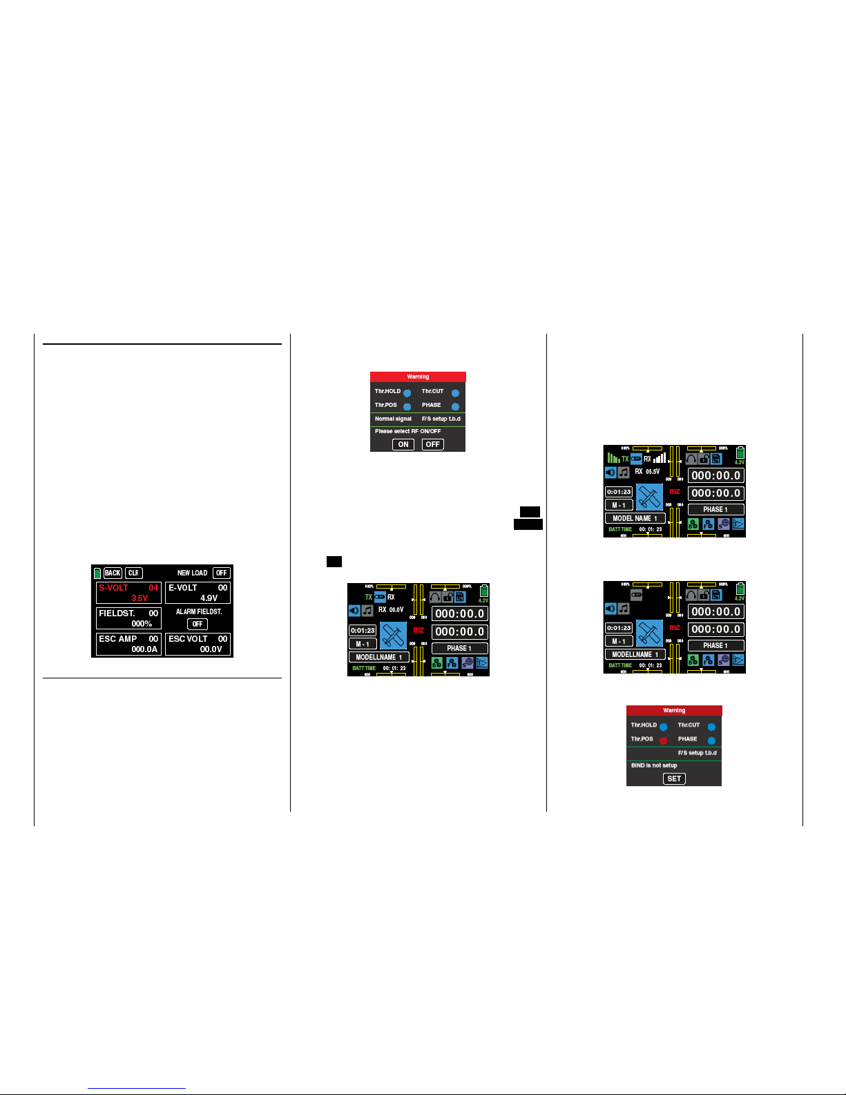
of the display it will appear the message:
At the same time, audible warning signals sound for
a few seconds.
You now have the option of waiting a few seconds
until the display disappears automatically or maintaining the HF transmissions by manually tapping the ON
button, or switching them off by tapping the OFF
button.
You can turn off a receiver that is on and then first
touch ON for demonstration purposes. You are then in
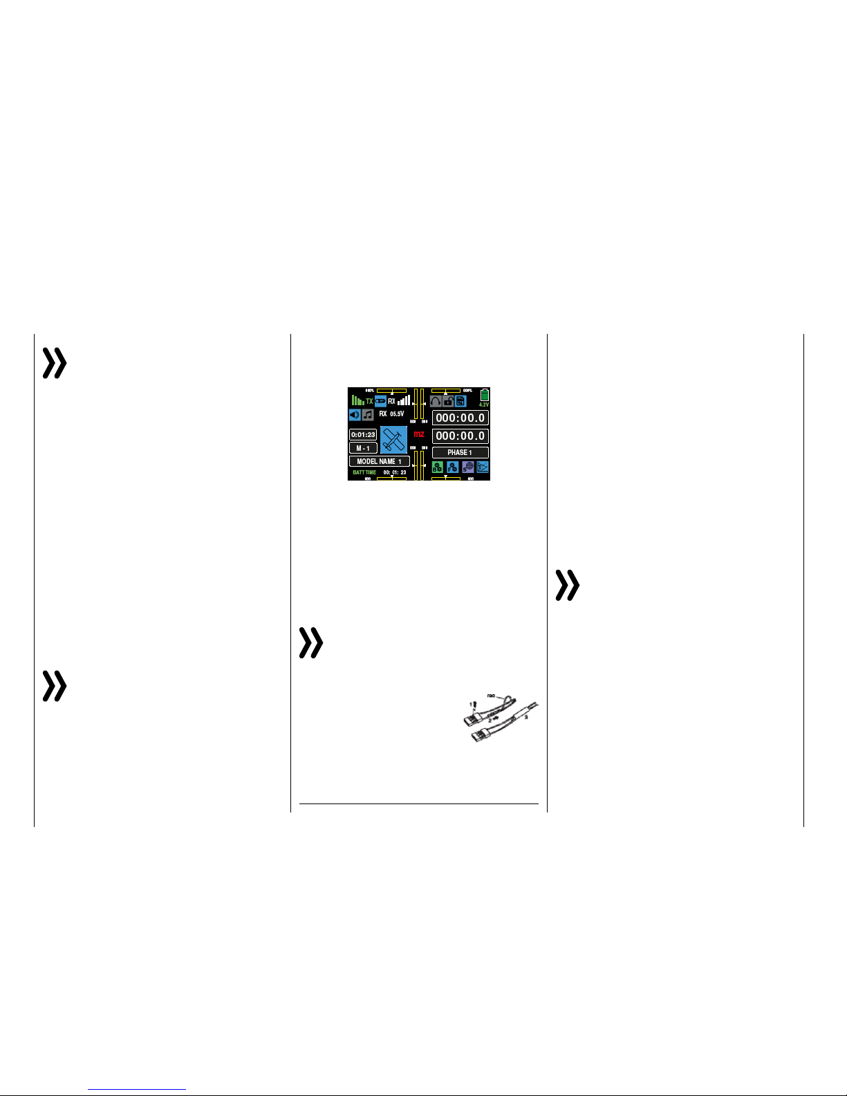
the basic display of the mz-24 HoTT Pro transmitter:
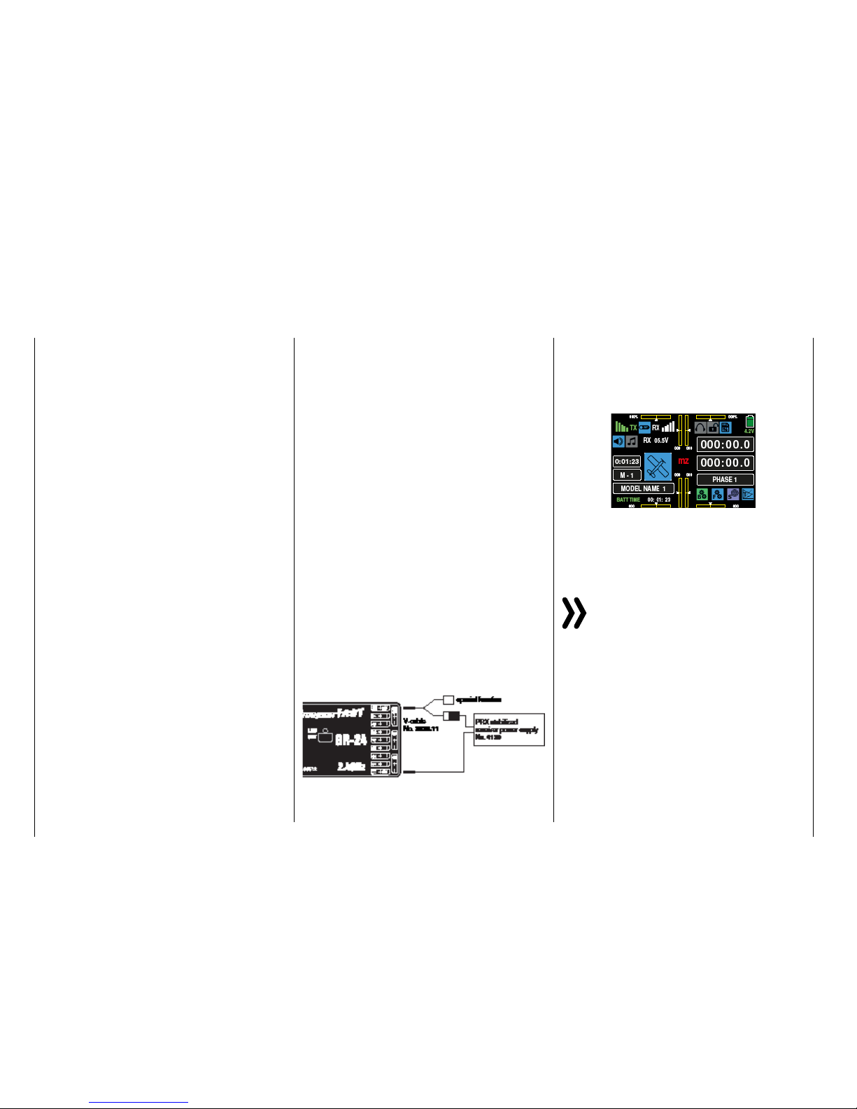
The blue switch symbol at the top left between the
green "TX" and the white "RX" means that the RF
transmission of the transmitter is on. (Otherwise the
symbol would be gray.)
The green "TX" and white "RX" on the left and right
of this switch symbol mean that the currently active
model memory has once been linked to a Graupner-
HoTT receiver but is presently not linked.
Once this link exists, the field strength display appears to the left of the green "TX" and to the right of
the white "RX", and the numeric display underneath
shows the current voltage of the receiver power supply, for example:
If the transmitter is turned on while the RF transmission is off, all of this information is not displayed, and
the RF switch symbol is gray.
If the following warning appears in the display after
the transmitter is turned on, ...
4 Starting up the transmitter
Page 5
... the currently active model memory is not linked to
any receiver. Tapping on the SET button you accede
immediately the under-menu »Transmitter setting«,
…
... where you can bind your receiver or, tapping on the
BACK button at the top left of the display to terminate
the procedure.
Tip
The basic procedure for initially programming a new
model memory starts on page 42.
Notices
• With this mz-24 HoTT Pro transmitter it is
possible to control up to 12 functions. Any
servos which are connected to connections
13 and higher remain in their middle position
by default and cannot be actuated by the
transmitter as standard.
• For the sake of maximum flexibility and to prevent unintentional misuse, control channels
5-12 are initially not assigned to any control elements, and the servos linked to these channels first remain in their middle position until
an operating element has been assigned. For
the same reason, nearly all mixers are inactive.
Similarly you will find at the begin of the paragraph's description "CTL Set".
• When training, linking or adjusting the remote
control, make sure that the transmitter antenna is always far enough from the receiver antennas. If the transmitter antenna is too close
to the receiver antennas, the receiver will
overdrive, and the red LED on the receiver will
shine to indicate that no signal is received. At
the same time, the feedback channel will stop
working, the field strength bar in the transmitter display will disappear, and the current receiver battery voltage will be displayed as 0.0
V. In this moment the transmitter is in the so
called Fail safe mode. That is, due to the loss
of reception, the servos remain in the last correctly received positions or after a short time
in the preset Fail-Safe positions, until a new
valid signal is received. In this case, move the
two antennas away until the displays return to
normal.
CAUTION
Never turn off the transmitter while operating the model! If this nonetheless acci-
dentally happens, do not panic, and wait
until the transmitter display goes dark which indicates that the transmitter is completely off. This
will take at least four seconds. After this time, turn
the transmitter on again. Otherwise, the transmitter may freeze directly after being turned on, and
you will be unable to control the model any more.
The transmitter may only be turned on again after
it has been turned off and the described procedure
has been correctly repeated.
5
Starting up the transmitter
Page 6
The display is basically operated by touching the desired field with a finger or the provided stylus:
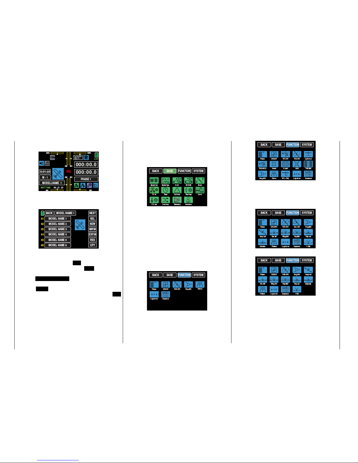
By touching the model memory field labeled "M 1" in
the above display with a finger or the provided stylus,
the "Model memory" selection menu opens.
In this sub-menu, you have the possibility for example
to change the model memory by touching the desired
model memory and then the SEL button.
Just as described on page , touch NEWto start programming a Programming a new model , or touch
the field MODEL NAME 1 at the upper edge of the
display to switch to the "Model name" entry menu,
or touch BACK at the top left to return to the previous menu item. In contrast, touch the button SW
[Change page] (generally using the rotation method)
which is also available in several menus to go to the
next page. In the above display of the model memory,
this would be to the display of model memories 07 …
12, etc.
Operating the display
Touching one of the three gear icons identified with
"B", "F", and "S", special selection menus open on
the bottom right from which you can switch to other
sub-menus. Starting with the green BASE menu, the
selection displaysappear as follows, ...
... it should be noted that the blue function menu described from page 120, Function menu contains
model-type-specific sub-menus and for this reason in
divided into a total of three paragraphs.
In the first paragraph starting on page 120 only the
sub-menus for "Vehicles", "Copters" and "Boats"
model types will be described. Because the same
sub-menus are also included in the "blue" menus of
the model type "Helicopter" and "Fixed-wing" models, their description is valid for all the model types
and for space reasons they will not be repeated in
both other paragraphs:
In the second paragraph, beginning on page 154,
exclusively the sub-menus related to the model type
"Helicopter" will be described excluding the above
mentioned "general menus":
And in the third paragraph, beginning on page 182
also excluding the previously described "general
menus", exclusively the sub-menus related to the
"fixed-wing" model type, in which the menus of a
"motor powered model" …
... distinguishes from the menus of a "Glider" model:
The purple System menu which can be accessed
tapping on "S" and whose description begins on page
220, is displayed as follows …
6 Operating the displays
Page 7
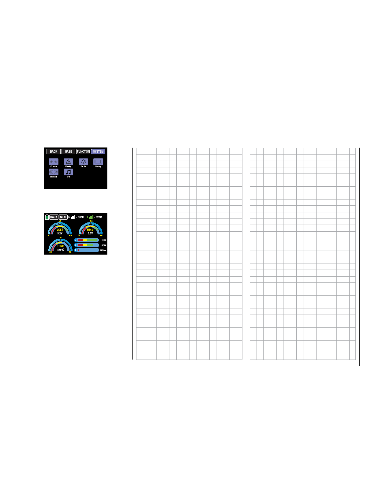
... and the display which can be accessed by tapping on "T" and detailed described from page 225 is
displayed for graphic representation of the telemetry
data e.g. so:
7
Operating the displays
Page 8
Warnings
In the display of the mz-24 HoTT Pro transmitter appear different warning windows. These can be divided
into two groups:
"Warning" display
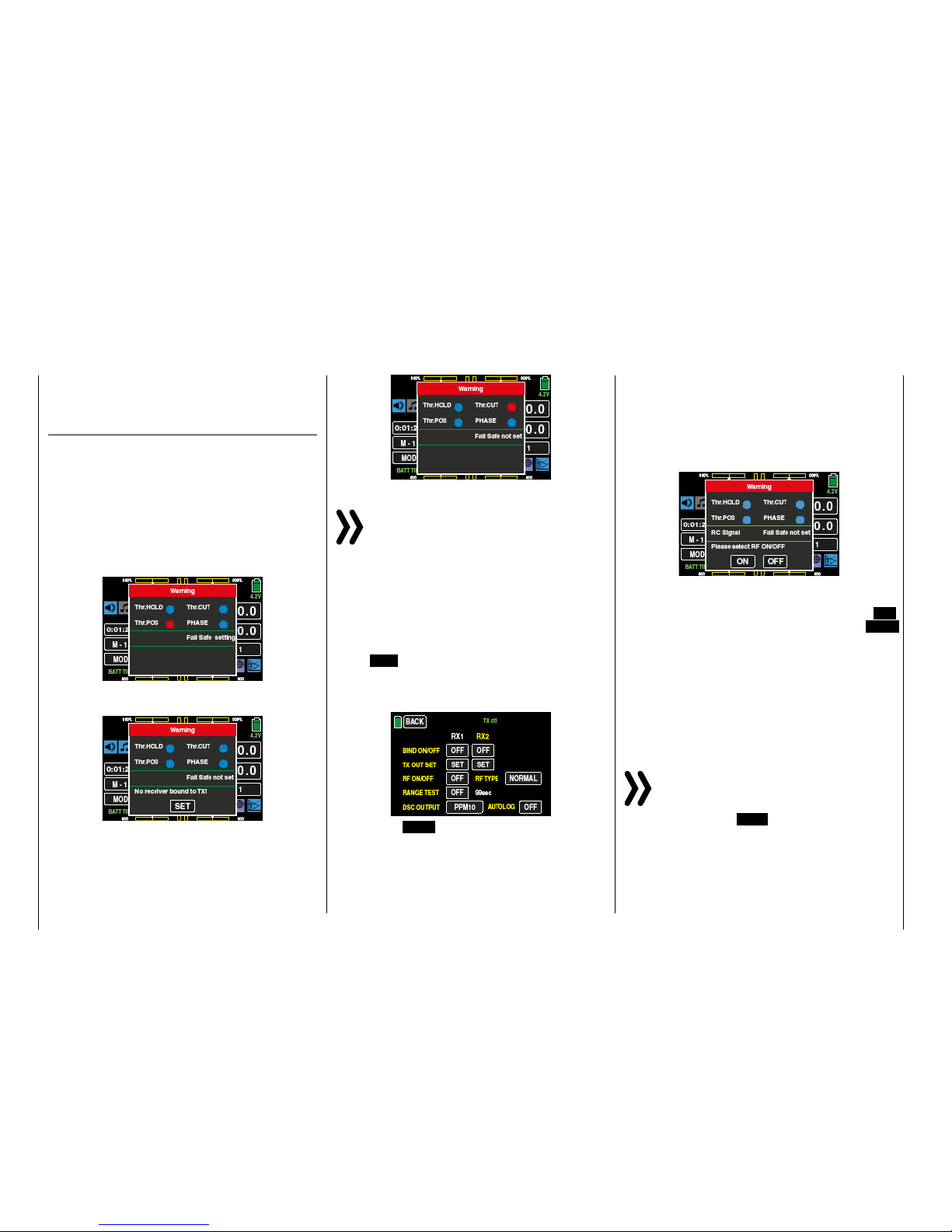
These warning windows primarily appear after the
transmitter is turned on and indicate certain operating
states. In the following illustration, for instance, the
red dot after "CH1-POS" indicates that the throttle
servo connected to the output 1 in fixed-wing models,
or the throttle servo and to output 6 on an helicopter
model, is not in the idle position and there is the risk
of a runaway engine. Until this state persists, the content of the underneath field are obscured for safety
reasons ...
... until the Throttle/Pitch control stick is not in the idle
area:
Basically the it is the same for the warning option "Thr.
HOLD", with the difference that the sub-men "WARN-
ING" of the system menu it can be selected, depend-
ing on the model, if the motor stop function on/off
must be worn:
Notice
In no case you should use the possibility of the
servo reverse of the channel 6 for helicopters and
channel 1 for other model types to reverse the
direction in which the related control stick works. Because the switch-on warning "CH1-Pos" as the "Thr.
HOLD" function do not follow this kind of reverse control
direction. To reverse the control direction use exclusively
the possibility offered by the "Pitch curve" menu for
helicopters models and "Throttle curve" for all the other model types.
Touch SET with a finger or the provided stylus to go
directly to the »TX ctl« display (Transmitter setting) in
which you can link the receiver to the model memory
as described in the related paragraph ...
Or touch the BACK button at the top left to terminate
the procedure.
If instead by switching the transmitter, there is already
a receiver bound to the model memory and inactive
Thr.POS warning, the transmitter will switch on and
the RF module will also be active. Otherwise in the
middle of the display it will standardly appear the following page and at the same time an acoustic warning will be emitted.
You now have the option of waiting a few seconds
until the display disappears automatically or maintaining the HF transmissions by manually tapping the ON
button, or switching them off by tapping the OFF
button.
In the field between the two green lines, the message
"RC signal" indicates that the transmitter is set to normal remote control. Alternately, messages such as
"TEACH signal" or "PUPIL signal" can appear here.
Another – possible – variant is to display "SET F/S" as
an indication that no fail-safe settings have yet been
made.
Notices
• By default,only the monitoring of the "Warn -
ing" sub-menu is activated in the display of
the sub-menu "Warning"of the system menu.
• By selecting REV in the "Thr.HOLD" line of
the "Warning" sub-menu the transmitter can
remind you to switch this function safely on.
8 Warnings
Page 9
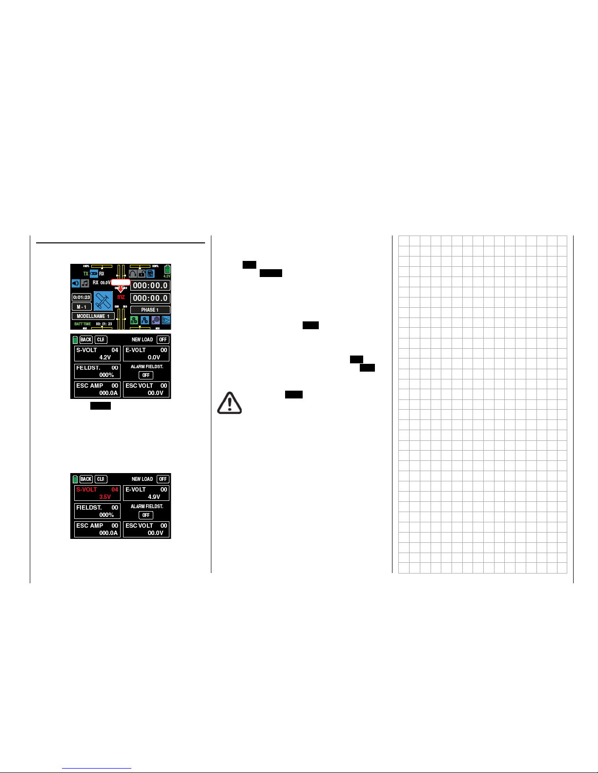
"Acute warning" display
You can open this display by touching mz in the middle of the transmitter's basic display ...
Touch
... and touch the BACK button at the top left to close
the display.
If acoustic warnings sound and the normal transmitter display is covered by this display, take note of the
message in red. An example would be because the
transmitter's supply voltage has reached the warning
threshold set in the sub-menu "»ETC. SET" of the
SYSTEM menu:
At the same time, the display contrast is reduced to
05 to save power.
This warning can be kept from reappearing by touching the ON button at the top right then deleted by
touching the BACK button at the top left in the display. (In specific cases, stop operating the model as
soon as possible and charge the transmitter).
The red number at the top right of each warning field
shows the number of current warnings; in the above
example, the warning is the fourth one. This count can
be deleted by touching the CLR button at the top left.
All other warnings in this display can be handled in
the same way. However, in the case of a field strength
alarm, you can also suppress other alarms triggered
by the low field strength by touching the ON button
under "STRENGTH ALARM" and switch it to OFF.
CAUTION
A switched OFF "Strength alarm" will not
automatically be set to the "ON" position
when the transmitter will be switched on
the next time.
9
Warnings
Page 10
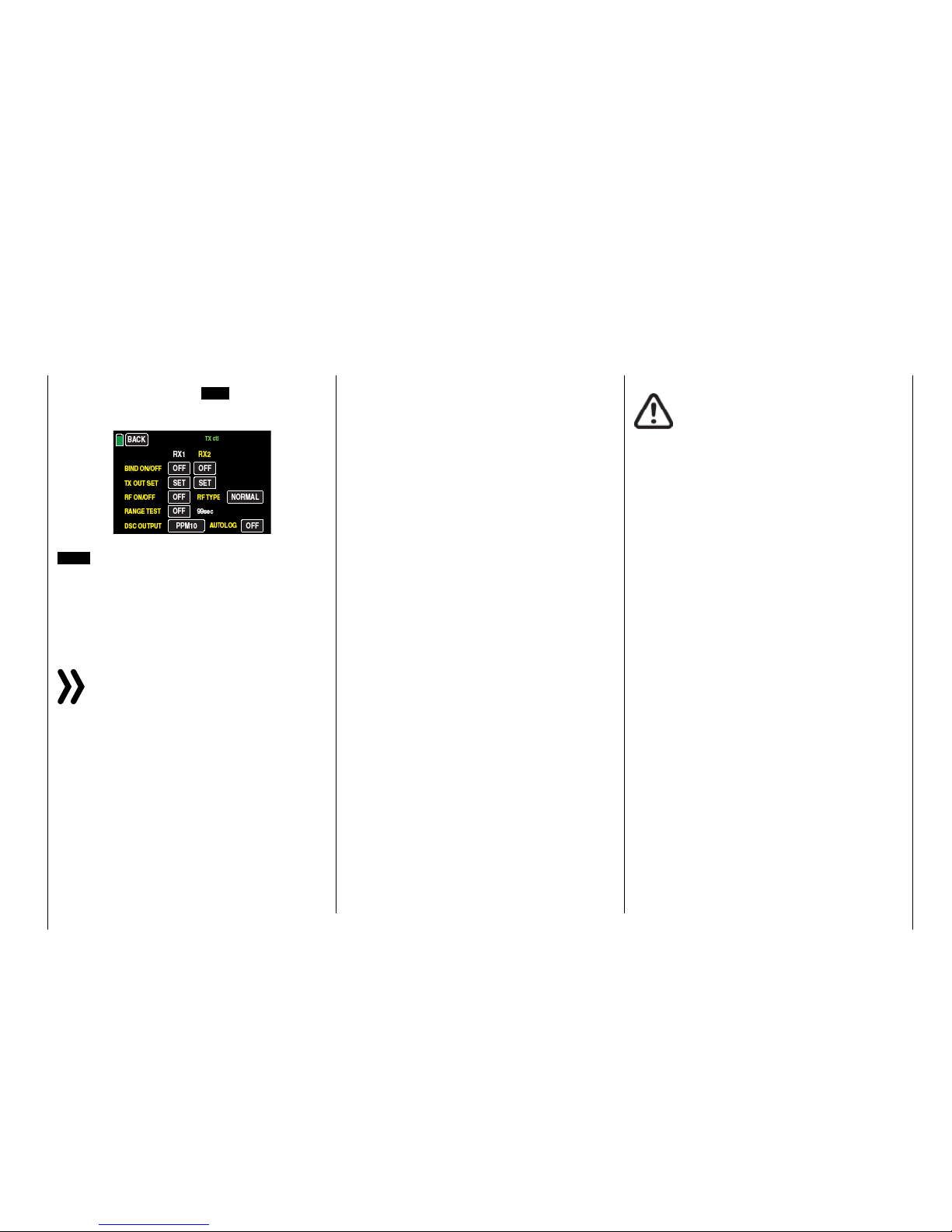
3. In the sub-menu »TX ctl«, depending on the number of channels used for the connected flight simulator or for the Training mode, you can select in
the line "DSC output" one of the following modes:
PPM10, PPM16, PPM18 und PPM24. Default setting: PPM10.
Notice
Given the numerous flight simulators on the market, it is possible that the contacts on the jack
plug or DSC module may have to be adapted by
Graupner Service.
Attention
When your transmitter is directly connected to a
desktop computer or laptop by a connecting ca-
ble (DSC cable) and/or a computer interface is
connected to your simulator, the transmitter may be destroyed byelectrostatic discharge. This type of connection should therefore only be used if you protect yourself
from electrostatic discharge while operating the simulator by wearing a commercially available grounding armband. Graupner therefore strongly recommends only
using wireless simulators.
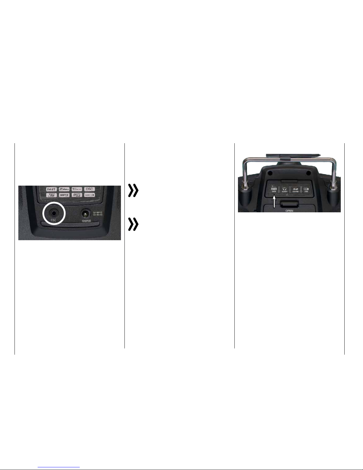
DSCsocket
The abbreviation "DSC" is from the initial letters of the
original function, "direct servo control". With the HoTT
system, "direct servo control" using a diagnostic cable is not possible for technical reasons.
The standard two-pin DSC socket on the back of the
mz-24 HoTT Pro transmitters functions as a TRAINER
or PUPIL socket as well as an interface for flight simulators or other external devices.
To ensure a correct DSC connection, observe the
following:
1. Perform any necessary adaptations in the menu.
To adapt to the transmitter to a trainer system,see
the description of the "Trainer" menu.
2. Connect the other end of the connecting cable to
the desireddevice while observing the relevant operating instructions.
Tip
Make sure that all the plugs are securely inserted in
the respective sockets, and only use the provided
plug-in connections with a 2-pin jack plug on the
DSC side.
The so-called DATA socket is found under the back
cover of the mz-24 HoTT Pro transmitters:
This is for connecting the optional Smart Box ( order
No. 33700) or alternatively for an external Bluetooth
module (No. S8351).
Further information on the Smart Box and the Bluetooth module can be found in the main Graupner FS
catalogue and on the Internet at www.graupner.de for
the respective product.
Data socket
10 Connection on the back side
Page 11
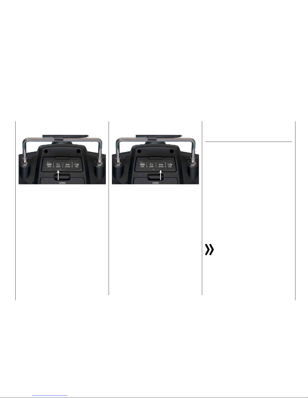
The headphone connection is found left of center under the back cover of the mz-24 HoTT Pro transmitter:
The socket is for connecting commercially available
ear buds or headphones with a 3.5 mmstereo jack.
(Not included in the set.)
When headphones are plugged in, the transmitter's
speaker is turned off and the stylized icon of a headphone is depicted in color and not gray in the basic
display.
In addition to acoustic signals from the transmitter,
signals and messages associated with the "Teleme-
try" menu are output via this connection. These messages are in German by default. Further information
can be found under "Announces" in the ""Teleme-
try"" section.
Ear phones port
Card slot
Micro-SD and micro-SDHC
Thecard slot for micro-SD und micro-SDHC memory
cards is found on the right of center under the back
cover of the mz-24 HoTT Pro transmitters:
In addition to the micro-SD memory cards that come
standard with the mz-24 HoTT Pro, all conventional micro-SD memory cards with up to 2 GB and micro-SDHC cards with up to 32 GB memory can be
used. The manufacturer recommends using memory
cards with a maximum of 4 GB since this capacity is
normally sufficient.
The memory card that is provided for the transmitter is inserted into the slot behind the cover with the
contacts facing up and then locked in place. After the
memory card is inserted, the transmitter cover can be
closed.
After the provided memory card included in the mz-
24 HoTT Pro set or another memory card has been
inserted in the transmitter at least once, the card is
ready for use directly after the transmitter is turned on.
If the transmitter is turned on after the memory card
is inserted, the stylized memory card icon is displayed
in color and not gray in the basic display. Otherwise, a
few folders are first created on the memory card.
Removing the memory card
Open the cover on the back. Press the SD card slightly toward the card slot to unlock it and then remove it.
Capturing / saving data
The data memory on the SD card is linked to timer
1: Once this starts, data storage also starts assuming that an appropriate memory card is in the card
slot and there is a telemetry link with the receiver. Data
storage stops when the timer 1 is stopped. Timer 1
starts and stops as described in the section "Timer".
The data writing on the memory card is remarked by
an animation of the memory card symbol.
After data storage is finished, an (empty) "Models"
folder and "LogData" folder appear on the memory card. Finally, the log files are saved in subfolders
called "Modelname" named according to the structure
0001_year-month-day.bin, 0002_year-month-day.bin.
If in contrast a model memory is still nameless, the
corresponding log files are saved in a subfolder entitled "NoName" after the memory card is removed
from the transmitter and inserted in the card slot of
a desktop or laptop computer. The data can be evaluated on a compatible computer using the programs
found on the downloads page for the transmitter under www.graupner. de.
Notice
Please note that for technical reasons NO data
representation is possible during the reproduction of MP3 data.
11
Connection on the back side
Page 12
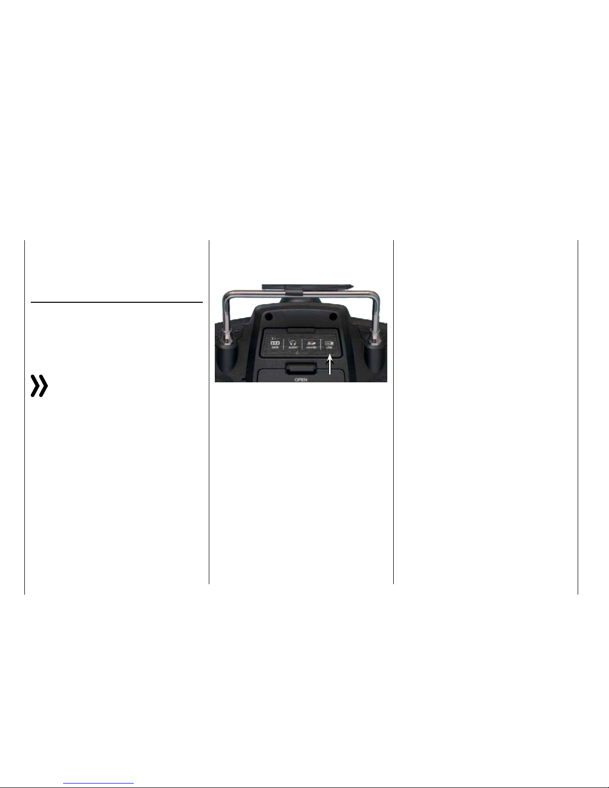
Mini-USB connection
Located under the rear cover of the mz-24 HoTT Pro
transmitter, there isa connection socket for software
updatesas well as the date andtime settingfrom a
desktop or laptop with one of the Windows operating
systems (XP, Vista, 7 ... 10):
The USB cable that comes with the set is plugged into
this socket. The procedure for obtaining software updates through a computer is described in the software
package instructions.
The software that the computer needs as well as the
appropriate USB driver can be found on the download
page at www.graupner.de for the respective product.
After the required driver and software are installed, the
transmitter can be updated as needed using this connection, or the date and time can be set.
Tip
In order to be aware of important software updates, you
should therefore register at https://www.graupner.de/
de/service/produktregistrierung.aspx. This will allow you
to automatically receive updates by e-mail.
Importing and exporting model memories
To exchange data between transmitters of the same
make or to backup data, model memories can be copied to the inserted memory card, or from the memory
card to the transmitter. More information can be found
in the section "Import from SD card" or "Export to SD
card"..
Notices
• Some of the special characters used in model names cannot be transferred to FAT and
FAT32file systemsdue to the specific restrictions of these file systems used by the memory cardand are therefore replaced by a tilde
(~) during the copying process.
• The model memories of the mz-24 and mz-
24 Pro transmittersare in principle compatible, BUT:
In order to import from an SD card in another
a transmitter type, the desired model memory
must be copied or moved to a corresponding
directory on a desktop or laptop. For example
from \\Models\mz-24 to \\Models\mz-24pro
or vice versa.
More information on "import from SD card"
After importing from an SD card,you always
need to check each and every model function and in particular adapt the control and
switch functionsto the respective transmitter.
12 Connection on the back side
Page 13

13
Personal notes
Page 14
Starting up the receiver
Preliminary remarks
Notice
With this mz-24 HoTT Pro transmitter it is possible to control up to 12 functions. Any servos
which are connected to the receiver outputs 13
and higher remain in their middle position by default and
cannot be actuated by the transmitter.
As described in the manual of the related receiver,
after switching it on a LED indicates the missing reception, so long as "its" transmitter is out of range or
switched off or simply the wrong model memory has
been selected in the transmitter. This means that a link
has not (yet) been established with a Graupner-HoTT
transmitter.
To establish a connection with the transmitter, first the
Graupner HoTT receiver must be "bound" to its model
memory in its Graupner HoTT transmitter. This process is known as "Binding". This "binding" is however
required only once for each receiver-model memory
combination or, after changes have been made to one
or more model memories (see page 39), only once
for each transmitter-receiver combination . Therefore
you need to perform a "binding" only after buying a
new transmitter or other receivers or for example if
you have changed model memory (and you can repeat it at any time).
Notice
If the LED of your receiver indicates that it is ready
for use and the receiver does not react to the SET
button and to the control movements, then you
would be better to check the polarity of your receiver
power supply.
On-board voltage display
When a telemetry link exists, the current voltage of
the receiver power supply appears in the transmitter
display in white.
Temperature warning
If the receiver temperature falls below a threshold
which can be set in the receiver (-10°C by default) or
exceeds a top warning threshold (+55°C by default)
which can also be set in the receiver, the receiver
emits a warning in the form of a beep that repeats
approximately once per second.
Note the installation instructions for the receiver, receiver antennas and servos on page 16.
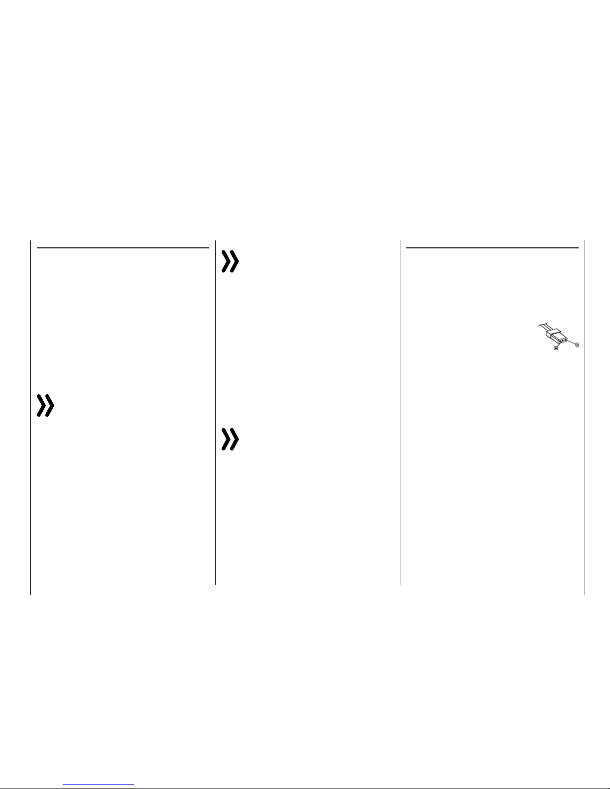
Notice
If you are using a speed controller with an integrated BEC* in addition to the receiver battery,
the plus pole (red cable) may have to be removed
from the 3-pin plug depending on the speed controller.
In this regard, take note of the related information in the
speed controller instructions.
Use a short screwdriver to carefully lift the middle tab of the plug (1),
remove the red cable (2), and use
electrician's tape to protect against
shorts (3).
Reset
To reset the receiver, hold down the SET button on the
top of the receiver while turning on the power.
If the reset is performed while the transmitter is
switched off or with a not bound receiver, the LED on
the receiver indicates the actual status according to
the description included in the package. If there is no
different description, release the button after about 3
seconds.
If the reset is performed with a not bound receiver, you
can then start a binding process at any time.
If a linked receiver is reset and the associated model
memory is active in the turned-on transmitter, the LED
indicates for about 2-3 seconds, accordingly to the
description included in the package of the receiver, to
indicate that your transmitter/receiver system is ready
to use.
Note
Through a RESET ALL of the settingsin the receiver are brought to the factory settings with the
exception of the HoTT synchronization informa-
tion!
If a reset is performed accidentally, all of these settings
that were made using the "Telemetry" menu in the re-
ceiver should be restored.
Resetting is particularly recommendable when you want
to switch a receiver to a different model. This makes it
easy to keep settings which do not match from being
transferred.
* BEC = Battery Elimination Circuit
14 Starting up the receiver
Page 15
Channel mapping
The function of each channel is determined by the
transmitter and not the receiver. The channel mapping can be changed directly in the receiver programming the "Telemetry" menu and indirectly through the
menu point "Transmitter output" of the base menu.
Installing the receiver
WhateverGraupner receiver system you use, the
procedure is the same.
For aircraft models, the receiver is installed behind
a strongbulkhead or it is protected against dust and
splash waterincar and ship models. When you install
the receiver, make sure that it is not excessively airtight to prevent it from overheating during operation.
The receiver may not directly touch the fuselage or
chassis since they can directly transmit motor vibration or impact from landing. When installing the receiver in a model with a gas motor, all of the parts
must be protected to prevent exhaust or oil from penetrating. This holds true in particular for the ON/OFF
switch that is installed in the shell of the model in most
cases.
Install the receiver so that the connecting cables for
the servos and power supply remain loose, and so
that the receiving antennas are at least 5 cm from all
large metal parts or wires that do not directly originate
from the receiver. This includes carbon fiber parts,
servos, electric motors, fuel pumps, all types of cables, etc. in addition to steel parts.
It is preferable to install the receiver away from all other installed parts at an easily accessible location in
the model. Servo cables may not be wound around
antennas or run next to them.
Note that the cables can shift under the influence of
acceleration during flight. You therefore need to make
sure that the cables cannot move to be directly adjacent to antennas. Moving cables can interfere with
reception.
Installing the receiver
Installing the receiver antennas
In case of single antenna, the orientation is not crucial.
In the case of diversity antennas (two antennas), the
active end of the second antenna should be at a 90°
angle from the end of the first antenna, and the distance between the active ends should ideally be more
than 125 mm.
If the fuselages are made of carbon fiber, the ends
of the antennas should extend from the fuselage by
at least 35 mm. If necessary, exchange the approx.
145 mm standard antennas for HoTT receivers with
the 300 mm or 450 mm long antennas No. 33500.2
or 33500.3.
Servo connections and polarity
The servo connections of the Graupner-HoTT receiver are numbered. The supply voltage runs through all
the numbered connections. The polarity of the plug-in
system cannot be reversed. When inserting the plug,
note the small bevels on the side. Do not apply force.
Attention
Do not reverse the polarity of these connections!
This can destroy the receiver and connected devices.
Notice
In compact receivers like the GR-12L HoTT the
outputs 1 … 6 are reverse of 180° if compared to
bigger receivers, for this reason we recommend
to pay a very lot of attention while you connect any plug
to the receiver. If applicable, use a V or Y cable (No.
3936.11).
15
Installing the receiver
Page 16
Installation notices
Components and accessories
Attention
As the manufacturer, Graupner|SJ GmbH recommends only using components and accesso-
ries that have been tested and accepted by
Graupner|SJ GmbH for suitability, functioning and safety. If this is done, Graupner|SJ GmbH will assume responsibility for the product.
However, Graupner|SJ GmbH assumes no liability for
products or accessories by other manufacturers that
have not been approved, and is incapable of evaluating
every single third-party product to determine if it can be
used safely.
Installing the switch
All of the switches must be installed so that they are
not influenced by exhaust or vibration. The switch
knob must be freely accessible over its entire operating range.
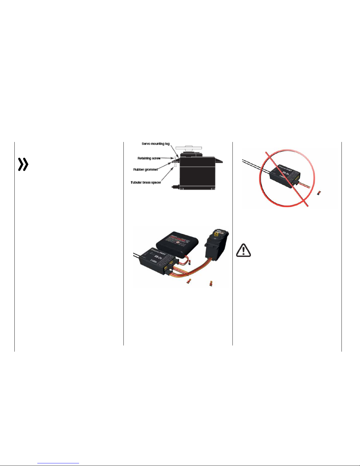
Installing the servos
Always install the servos with the provided rubber vibration damper, see the following installing notices.
This is the only way to protect them somewhat from
excessive vibration.
• Install the servos on rubber grommets with tubular
brass spacers to protect them from vibration. Do
not overtighten the fixing screws; this could counteract the vibration protection provided by the rubber grommets. The system offers both safety and
vibration protection for your servos when the servo
fixing screws are properly tightened. The following figure shows how to correctly mount a servo.
The brass spacers are inserted from below into the
rubber grommets:
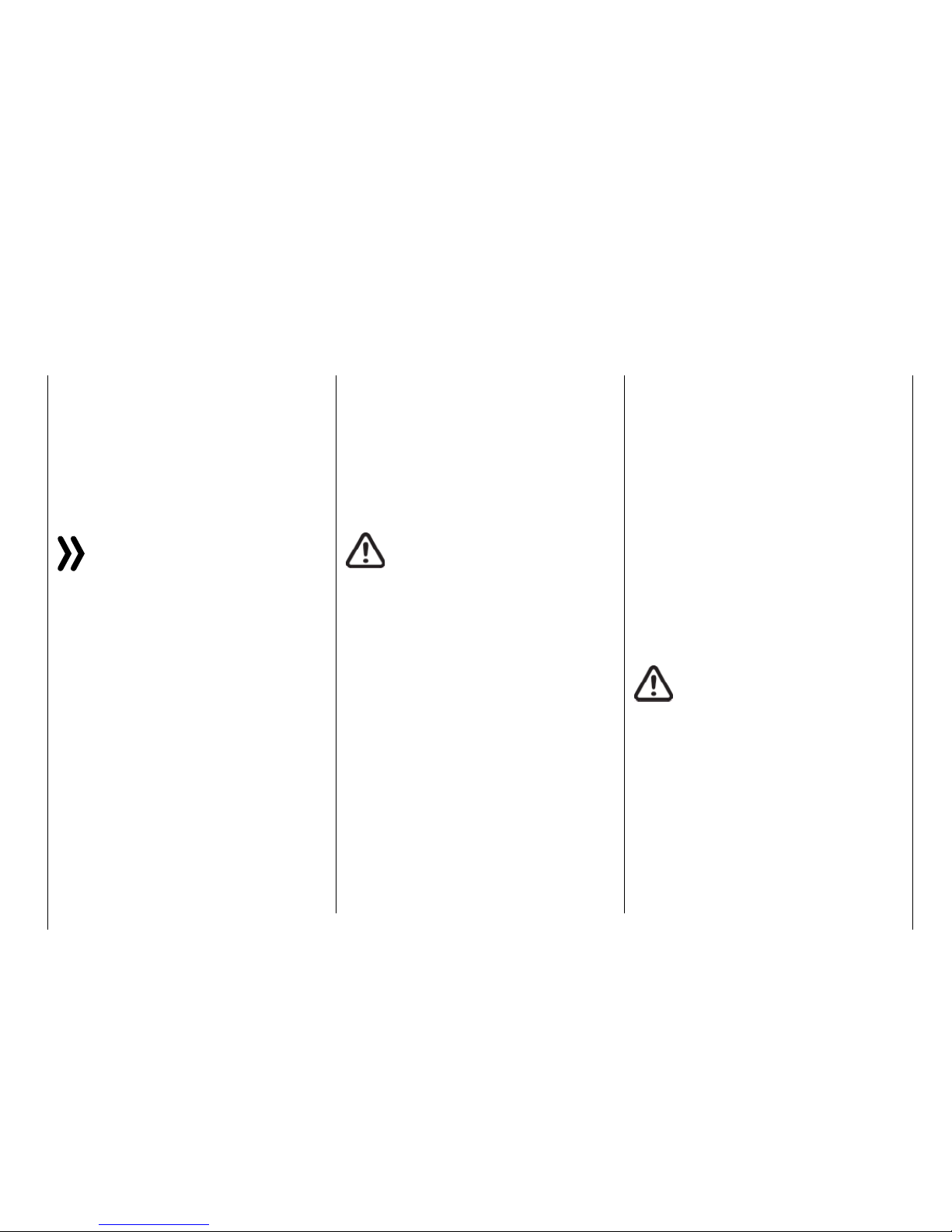
... they should never be connected as follows:
• In contrast, the sequence for connecting the servosdepends on the model type. Refer to the connection assignments for Helicopter models and
Fixed-wing models.
WARNINGS
• Technical defects of an electrical or
mechanical naturemay cause motors
to start without warning,or may generate flying partswhich can cause significant injuryto you and others!
• Avoid every kind of short-circuit!
Short-circuits can destroy parts of the
remote control system and cause serious burns or explosions depending
on the circumstances and the battery
charge.
• All parts driven by the motor such as
air and water propellers as well as helicopter rotors, exposed gears, etc.
always pose an injury hazard. Never
touch these parts! A fast-rotating propeller can cut off a finger! Make sure
that no other objects come into contact with driven parts.
• The servo arms must be freely movable throughout
their operating range. Make sure that no linkage
parts block the free movement of the servo.
• Connect the receiver's power supply cable(s) or
the servo connecting cable to the receiver as follows ...
16 Installation instructions
Page 17
• Once the battery is connected or the
motor is running, always maintain a
safe distance from the hazard area
posed by the propulsion system!
• During the programming process,
make sure that a connected gas engine or electric motor cannot accidentally start. Disconnect the fuel supply
or drive battery beforehand.
Notices
• Protect all equipment from dust, dirt, moisture
and other foreign parts. All equipment must be
protected from vibration as well as excessive
heat or cold. The models may only be operated remotely in normal outside temperatures
such as from -10°C to +55°C.
• Avoid shock and pressure. Check for damage to the housing and cables. Devices that
become wet or damaged may not be used
anymore even if they dry out.
• Only use the components and spare parts
that we recommend. Always use matching,
original Graupner plug-in connections of the
same design and material.
• When running the cables, make sure that they
are not excessively tight, kinked, or severed. A
sharp edge can also damage insulation.
• Make sure that all of the plug-in connections
are tight. When disconnecting the plug-in
connections, do not pull the cables.
• No changes may be made to the devices. This
will void permission to use the device along
with the warranty. If appropriate, send the
relevant device to the responsible Graupner
Service Center
Range and function test
Before every use, check the range and functioning.
Firmly secure the model, and make sure that no one
is nearby.
Perform at least one complete function test on the
ground, and run through an entire flight simulation to
determine if there are any problems with the system
or the programming of the model. Always follow the
instructions under Range test.
WARNING
If the range and function test as well as
the flight simulation are not performed
completely and conscientiously, malfunctions may go unrecognized and reception may be
lost which could cause a loss of control or even
cause the model to crash. This canresult in major
property damage and/or personal injury.
17
Installation instructions
Servo noise filters for extension cables
No. 1040
The servo noise filter is required when using lon-
ger-than-usual servo cables. The filter is connected
directly to the receiver output. In critical cases, a second filter can be placed on the servo.
Electrical ignitions
Ignition systems of gas engines also generate interference that can impair the functioning of remote controls.
The power for electrical ignitions should always be
from a separate source.
Only use interference-suppressed spark plugs and
spark plug connectors and shielded ignition cables.
The receiver should be at a sufficient distance from
the ignition system.
Model function
WARNING
• Neverfly the model over observersor
other pilots. Never endanger people
or animals. Never fly close to power
lines. In addition, never operate your
model close to locks and open nautical traffic. Do not operate your model
on open roads, highways, paths, public walkways, etc.
• Never turn off the transmitter while
operating the model! If this nonetheless accidentally happens, do not panic, and wait until the transmitter display goes dark which indicates that
the transmitter is completely off. This
will take at least three seconds. After this time, turn the transmitter on
again.
Page 18

• Otherwise, the transmitter may freeze
directly after being turned on, and you
will be unable to control the model.
The transmitter may only be turned
on again after it has been turned off
and the described procedure has been
correctly repeated.
• When operating towed models, maintain a minimum distance of approximately 50 cm between the participating receivers or their antennas. Using
the satellite receiver is an option. Otherwise, malfunctions from the feedback channel are possible.
Checking the transmitter and receiver batteries
Stop operation and recharge the transmitter battery at
the latest when the transmitterbattery is running low,
the message "Charge the battery!" appears in the
display, andan acoustic warning sounds.
Regularly check the battery charge, especially of the
receiver battery. Do not wait until the movements of
the rudder are noticeably slower. Replace dead batteries in a timely manner.
Always follow the manufacturer's charging instructions, and charge the battery for the indicated time.
Do not charge the batteries without monitoring them.
Never attempt to charge dry batteries. An acute explosion hazard exists.
All batteries must be charged before each use. To prevent short-circuits, first plug the banana plugs of the
charging cable into the charger (make sure the poles
are correct). Then plug in the charging cable plugs into
the sockets of the transmitter and receiver battery.
If you are not going to use your model for a while,
disconnect all power sources.
Never use rechargeable or replaceable batteries with
damaged, defective or different cell types; that is, a
mixture of old and new cells, or cells by a different
manufacturer. Combinations of old and new cells or
cells from different manufacturers.
Capacity and operating time
The following applies to all power sources: The capacity decreases with each charge. At low temperatures,
the internal resistance increases while the capacity
decreases further. As a result, the battery's ability to
discharge and retain power is reduced.
Frequently charging and/or using battery care programs can also gradually reduce the capacity. Nevertheless, check the capacity of power sources at least
every 6 months, and replace them if their performance
is significantly low.
Only use original Graupner rechargeable batteries!
18 Installation instructions
Page 19

19
Personal notes
Page 20
To safely operate the model, a reliable power supply
is required. If the receiver voltage shown on the transmitter display always drops or is generally (too) low
even though the linkage moves freely, the battery is
full, the cross-section of the battery connecting cable
is sufficient, and the transition resistance at the plugin connections is minimal, etc., observe following:
First make sure that the battery remains fully charged
when initially operating the model. Make sure that the
resistance of the contacts and switches is low. Measure the voltage drop over the installed switch cables
under a load since even robust, new switches cause
a voltage drop of up to 0.2 V. This value can be several times higher due to aging and oxidation of the
contacts. In addition, constant vibration and shaking
of the contacts also gradually increase the transition
resistance.
Furthermore, even small servos such as a Graupner/
JR DS-281 draw stall current to 0.75 A when you stop
under a load. Four of these servos in a foam airplane
can hence draw up to 3 A from the on-board power
supply.
Furthermore, servos connected to a 2.4 GHz receiver
receive control pulses more frequently than comparable receivers in the classic frequency range. This affects the power consumption of the receiver system
as well as the characteristic of many modern digital
servos of maintaining the last position specified by
the last control pulse until the next pulse arrives.
You should not only therefore choose a power supply
that does not fail under a permanent high load and
always provides sufficient voltage. To calculate the required battery capacity, add at least 350 mAh for each
analog servo, and at least 500 mAh for each digital
servo.
Using this method, a battery with 1400 mAh represents the absolute minimum for supplying power to
a receiver with four analogue servos. In your calculation, also include the receiver which requires about
70 mA due to its bidirectional function.
Apart from the above considerations, it is generally
recommendable to connect the receiver to the power
supply using two cables. As usual, connect cable "1"
to the "6+B" or "12+B-" output of a GR-16 or GR24 receiver, and cable "2" to the opposite end of the
connector strip labeled "1+B-" or "11+B-" of the receiver. When, for example, using a switch or voltage
regulator with two power supply cables leading to the
receiver. Between the cable and receiver, you can use
a V or Y cable (No. 3936.11, see figure) if one or both
receiver connections also need to be connected to a
servo, speed controller, etc. With the double connection to the switch or voltage controller, you not only
reduce the risk of a cable rupture but also ensure an
even power supply to the connected servos.
If you connect a separate battery to each battery
connection, be sure that each of the batteries have
the same rated voltage and capacity. Never connect
different battery types or batteries with strongly different charges since this can cause an effect similar
to a short circuit. In such cases for safety reasons,
insert voltage stabilizing elements such as the PRX5A receiver power supplies between the batteries and
receiver:
For safety reasons, never used battery boxes or dry
batteries.
The voltage of the on-board power supply is graphically represented, when the model is in use, in the
upper right side of the display so as underneath in
green numerically:
If the voltage falls below the warning threshold (normally 3.8 V) which can be adjusted in the "RX SERVO
TEST" display of the "SETTING & DATA VIEW" of the
"Telemetry" menu, a visual and acoustic low-voltage
warnings are generated.
Attention
Thebattery level should be checked regularly. Do
not wait to charge the battery until the voltage
decreases enough for a warning signal to be
generated.
Tip
A summary of the batteries, chargers and measuring
devicesfor checkingthe power sources can be found
in the main Graupner FS catalogue as well as on the
Internet at www.graupner.de.
20 Installation notice - Receiver system power supply
Receiver system power supply
Page 21
Charging the receiver battery
The charging cable (No. 3021) can be connected directly to the receiver battery to charge it. If the battery
in the model is connected by a power supply cable
(No. 3046, 3934, 3934.1 or 3934.3), the battery is
charged via the charging socket integrated in the
switch, or a separate charging connection. The switch
for the power supply cable must be set to "OFF" for
charging
Polarity of the receiver battery plug
.
Receiver system power supply
NiMH battery packs with 4 cells
With a traditional 4-cell pack, you can reliably operate
your Graupner HoTT system providing that the above
conditions are observed, and assuming that the packs
have a sufficient capacity and charge.
NiMH battery packs with 5 cells
Battery packs with five cells offer greater leeway in
comparison to 4-cell packs.
You should note, however, that not every servo available on the market can handle the voltage from a
5-cell pack over the long term, especially when the
pack is freshly charged. Some of these servos audibly
"growl" when operated with a 5-pack.
Notice
You should therefore note the specifications for
your servo before you choose to use a 5-cell
pack.
LiFe packs with 2 cells
Given the above considerations, these cells are the
best choice.
LiFe cells are also available in a hard plastic housing
to protect against mechanical damage. Like lithium
polymer cells, LiFe cells can be charged quickly with
suitable chargers and are comparably robust.
In addition, this type of cell can undergo significantly
more charging/discharging cycles than conventional
LiPo batteries. The comparatively high rated voltage
of 6.6 V of two cell LiFe battery packs does not pose
any problems to Graupner HoTT receivers or the servos, speed controllers, gyros, etc. which are approved
for operation with this higher voltage.
Attention
However, practically all of the previously marketed servos, speed controllers, gyros, etc. as well
as many which are offered today have a permissible operating voltage range of 4.8 to 6 V. Stabilized
voltage control such as the PRX (No. 4136) is therefore
needed to connect them to the receiver. Otherwise, the
connected devices may quickly become damaged.
LiPo packs with 2 cells
LiPo batteries are lighter yet they offer the same capacity of NiMH batteries. LiPo batteries also come in
a hard plastic housing to protect against mechanical
damage.
The comparatively high rated voltage of 7.4 V of two
cell LiPo battery packs does not pose any problems
to Graupner HoTT receivers or the servos, speed controllers, gyros, etc. which are approved for operation
with this higher voltage.
Attention
However, practically all of the previously market-
ed servos, speed controllers, gyros, etc. as well
as many which are offered today have a permissible operating voltage range of 4.8 to 6 V. Stabilized
voltage control such as the PRX (No. 4136) is therefore
needed to connect them to the receiver. Otherwise, the
connected devices may quickly become damaged.
21
Installation notice - Receiver system power supply
Page 22

Lithium-ion (LiIo) and lithium polymer (LiPo) batteries
require special treatment. This is true when charging,
discharging, storing and all other types of handling.
Observe the following specifications:
Charging Graupner LiPo/LiIo batteries
• Since Graupner|SJ GmbH is unable to monitor
whether the batteries are correctly charged and
discharged, all warranties are voided upon incorrect charging or discharging.
• Only use the approved chargers with the associated charging cables to charge lithium ion/lithium
polymer batteries. Any alterations to the charger
and/or charging cables can cause serious damage.
• The maximum charging capacity must be limited
to a factor of 1.05 of the battery capacity.
Example: 700 mAh battery = 735 mAh max.
charging capacity
• To charge and discharge lithium-ion/lithium polymer batteries, only use the plug-in charger in the
set, or the specially designed charger/dischargers
by Graupner, see under www.graupner.de.
• Make sure that the number of cells, charging cutoff and discharging cutoff voltage are set correctly.
Refer to the operating instructions of your charger/
discharger.
• Under these prerequisites, Graupner lithium-ion/
lithium polymer batteries can be charged with a
maximum 2 C (1 C corresponds to the cell capacity) charging current. Starting at a maximum 4.2 V
per cell, continue charging at a constant 4.2 V per
cell until the charging current falls below 0.1... 0.2
A.
• Do not charge with more than 4.20 V per cell.
This would permanently damage the cell and may
cause a fire.
To keep from overcharging individual cells within
the pack, set the cutoff voltage to between 4.10...
4.15 V per cell in order to extend the battery life.
• The permissible temperature range for charging
and discharging lithium ion/lithium polymer batteries is 0... +50°C.
• Batteries as well as individual cells are not toys
and must be kept from children. They must therefore be stored out of the reach of children.
• Keep batteries away from infants and small children. If a battery is swallowed, immediately consult a physician or go to an emergency room.
• Never place a battery in a microwave or under
pressure. This may cause smoke, fire or an explosion.
• Do not disassemble lithium ion/lithium polymer
batteries. Disassembling a battery can cause internal short-circuits. This can result in the release
of gas, fire and explosion, or other problems.
• The electrolyte and electrolyte vapors within lithium-ion/lithium polymer batteries are hazardous to
health. Avoid direct contact with electrolytes. If the
electrolyte comes into contact with your skin, eyes
or other body parts, use a large amount of fresh
water for rinsing and then consult a doctor.
• Before each use, make sure that the batteries are
in a satisfactory condition. Defective or damaged
cells or batteries may not be used.
• Cells and batteries may only be used in accordance with the technical specifications for the specific cell type.
• Batteries and cells may not be heated, burned,
short-circuited or charged with excessive current
or with reversed polarity.
Safety and handling instructions
for lithium-ion (LiIo) and lithium polymer (LiPo) rechargeable batteries
• If handled improperly, there is a danger of fire, explosion, irritation and burns. To extinguish a fire,
use a fire extinguishing blanket, CO2 extinguisher
or sand.
• If the batteries overheat, proceed as follows:
Disconnect the battery, and place it on a non-flam-
mable surface (such as concrete) until it cools
down. Never hold the battery in your hand due to
the risk of explosion.
• Batteries from parallel-connected cells, and combinations of old and new cells, cells of different
makes, sizes, capacities, manufacturers, brands
or type may not be used.
• Batteries which have been installed in a device
should always be removed when the device is
not being used. Always turn devices off after you
have finished using them to prevent battery drainage. Dead lithium-ion/lithium polymer batteries are
considered defective and may not be reused.
• Be sure to charge the batteries in a timely manner.
While they are being charged, the batteries must
be placed on a non-flammable, heat-resistant and
non-conductive surface. Combustible or highly
flammable objects are to be kept away from the
charging area.
• Batteries must be monitored while they are being
charged. The maximum charging current specified
for the respective cell type may not be exceeded.
• You may only charge a pack of series-connected
lithium-ion/lithium polymer batteries all at once as
long as the voltage of the individual cells does not
deviate by more than 0.05 V, or if the differences in
voltage are monitored and equalized by a balancer connection using a balancer or equalizer during
charging.
22 Safety and handling instructions for lithium-ion/lithium polymer batteries
Page 23

The 1s lithium-ion battery in the set comes with a
special safety shut off. The voltage differences between individual cells are therefore not balanced
by means of the usual balancer plug-in connection.
• If the battery heats up above 60°C while it is being charged, stop charging and let the battery cool
down to approximately 30°C.
• The batteries may not be modified. Do not directly
solder or weld the cells.
• To avoid deformation, avoid excessive mechanical
pressure.
• Make sure to observe the charging and discharging instructions.
Storage
LiIo/LiPo cells should be stocked with about 50% of
their nominal capacity. If the cell voltage falls below 3
V during the stocking, the lithium ion/lithium polymer
cells must be recharged to 50% of the full capacity.
Otherwise, the battery will die during storage and become useless.
Special instructions on discharging Graupner
LiIo/LiPo polymer batteries:
• A continuous current of approximately 1 C does
not pose a problem for Graupner lithium-ion/lithium polymer batteries. If the current is higher, refer
to the instructions in the catalogue. Bear in mind
the maximum load for the plug-in system (see the
maximum discharge current indicated on the battery label).
• Discharging below 2.5 V per cell will damage the
cells and should therefore be avoided at all costs.
• The batteries should never be short-circuited.
Short-circuits generate a very high current which
heats up the cells. This causes a loss of electrolyte, gas formation or even explosions. Graupner
LiIo/LiPo batteries should therefore be kept away
from and not touch conductive surfaces due to the
short-circuit hazard.
• The battery's temperature during discharging
should never exceed +70°C. If this occurs, make
sure that the battery is sufficiently cooled, or reduce the discharge current. The temperature can
be easily checked using the infrared thermometer
(No. 1963). However, the battery may not be discharged using the transmitter's charging socket.
This socket is not designed for this purpose.
Additional instructions on handling
• The battery capacity decreases each time it is
charged and discharged. Charging when the temperature is too high or too low can also gradually
reduce the battery's capacity. After 50 cycles, the
battery capacity of models is only 50-80% of that
of a new battery due to the occasionally high discharge current and induction current of the motor,
even when all charging and discharging instructions have been followed.
• Batteries may only be series-connected or parallel-connected in exceptions since the cell capacity
and charge can differ. The battery packs that we
supply are therefore preferable.
• The connections of lithium ion/lithium polymer
batteries are not as robust as other batteries. This
holds true particularly for the plus pole connection.
The connections can easily break.
Cells connection
Attention
Direct soldering on the battery cells is impermissible. The heat from direct soldering can damage
battery components such as the separator or
isolator.
Battery connections should only be created by spot
welding in the factory. If the cable is missing or severed, have it repaired professionally by the manufacturer or dealer.
Replacing individual battery cells
Attention
Individually battery cells may only be exchanged
by the manufacturer or dealer and not by the
user.
Do not use damaged cells
Damaged cells may not be used.
Indications of damaged cells include damaged hous-
ing packaging, deformed cells, the smell of electrolyte
or leaking electrolyte. The battery may not be used in
these cases.
Damaged or useless cells are considered hazardous
waste and must be disposed of properly.
Contact with liquids
Batteries may not be immersed in liquid such astap
water, sea water or beverages. Avoid all contact with
liquids of any kind.
23
Safety and handling instructions for lithium-ion/lithium polymer batteries
Page 24

Definition of terms
Control function, control, function input, control channel, mixer, switch, control and logical switch
To make it easier to use the Part 2 of the manual, we
offer a few definitions of terms that appear repeatedly
in the manual.
Control function
A control function is understood as the signal for a
specific control function independent of the signal
within the transmitter. In fixed-wing models set e.g.
the control signals would be throttle, rudder or aileron;
in helicopter models, these would be e.g. pitch, roll
or nick.
The signal of a control function can be transmitted
directly into one control channel or through a mixer
to several control channels. A typical example of the
latter are separate aileron servos, or the use of two roll
or elevation servos in helicopters. The control function
includes the influence of the mechanical control path
on the corresponding servo. This can be spread or
concentrated and modified from linear to highly exponential.
Controls
Controls are the control elements on the transmitter
that are activated directly by the pilot that control the
connected servos, speed controllers, etc. on the receiver. These include:
• The two control sticks for control functions 1 to
4, including the related trims. These four functions
in all the six model types (vehicle, boat, copter,
helicopter, motor airplane and glider) can be exchanged using the mode setting in the software,
such as throttle left or right. Throttle/brake or throttle/pitch left or right. The control stick function for
Throttle/brake flap control for fixed-wing models
or throttle/pitch control in helicopters is frequently
identified as the THR control (channel 1).
• the four proportional dials (DV1 … DV4)
• The two side proportional rotary controls SL1 and
SL2 mounted on the bottom.
• Switches S1 … S8
• the INC/DEC buttons DT1 and DT2
With the type DV and SL proportional controls as well
as the INC/DEC buttons, the servos directly follow the
control position, whereas only a two or three-stage
adjustment is possible with a switch.
The assignment of the controls and switches to the
servos 5 …12 is freely programmable.
Function input
This is an imaginary point in the signal flow and should
not be confused with the control connection on the
printed circuit board. The selected control mode and
the settings "TX OUT SET" line of the ""CTL Set""
sub-menu (transmitter setting) of the base menu influence the sequence beyond the physical connecting
points and this can generate differences between the
number of function inputs and the number of subsequent control channels.
Control channel
From the point at which a signal contains all control
information necessary for a particular servo, whether
directly from the control or indirectly via a mixer, the
term control channel is used.
For example, the "aileron" control function of a fixedwing model for the model type "2AILE" is divided into
control channels for the left and right aileron. Analogously,the "Roll" control function for the helicopter
model "3Sv(2Roll)" governs the controlchannels for
both the left and right roll servo.
This signal is only influenced by the settings made in
the sub-menus "E.P.A" (servo path/servo limit), "REV/
SUB" (servo direction reverse/delay) and "Sub-Trim"
(servo middle and neutral position) to adjust the servo, and possibly the settings in the sub-menu "Out.
Swap" (transmitter output) and is then transmitted by
the transmitter through the RF module. Once it arrives
in the receiver, this signal may be modified by settings
saved in the "Telemetry" menu, after which it controls
the associated servo.
Mixer
The transmitter program contains a variety of mixing
functions. These allow a control function to influence
several control channels and as final result several
servos or even many control functions to influence the
same one servo.
In this context, you can refer to the numerous mixing
functions.
Switch
The series of toggle switches S1 … S8 can also be included in the control programming. The switches are
however generally also intended to switch program
options such as to start and stop the timers, turn mixers on and off, as trainer switches etc. Each of the
switches can be assigned any number of functions.
Related examples are listed in the manual.
Control switch
Since it is occasionally practical to automatically
switch a timer or a function on or off when a control
is in a specific position (a stopwatch turns on/off to
measure engine operating times), the program for the
mz-24 HoTT Pro transmitter also allows you to program control switches.
24 Definition of terms
Page 25

With these program switches, all you have to do is
specify the switching point along the control path in
the direction of switching. More detailed information
are easily available in the paragraph "Controls and
switches assignment".
Logical switch
Through this option two switches, controls and/or
logical switches or the favorite combination of them,
can be interconnected in an "AND" or "OR" switch. A
total amount of 8 logical switches "L1 … L8" can be
programmed, see description in the "Logical switch"
menu.
25
Definition of terms
Page 26
Control and switch assignment
Basic procedure
In many places in the program, you can actuate a
control function with a freely selectable control (ST 1
… 4, DV1 … D4, DT1 and DT2, SL1 and SL2), switch
(S1 … 8), or switch between settings with a switch
(S1 … 8), control or logical switch (see below). In both
cases, multiple assignments are always possible. (The
distinction between a control and switch is explained
in the section "Definition of terms").
Notice
It should be noted however that incorrect responses may arise from functional overlaps such
as using the same physical switch as a switch to
switch between Phase switch and as a control for Phase
trimming. Change also your switch assignment.
Since the same method is used to assign the controls,
switches control and logical switches in all relevant
menus, the basic procedure will be explained at this
point which will allow you to focus on the specifics in
the detailed menu descriptions.
Control and switch assignment
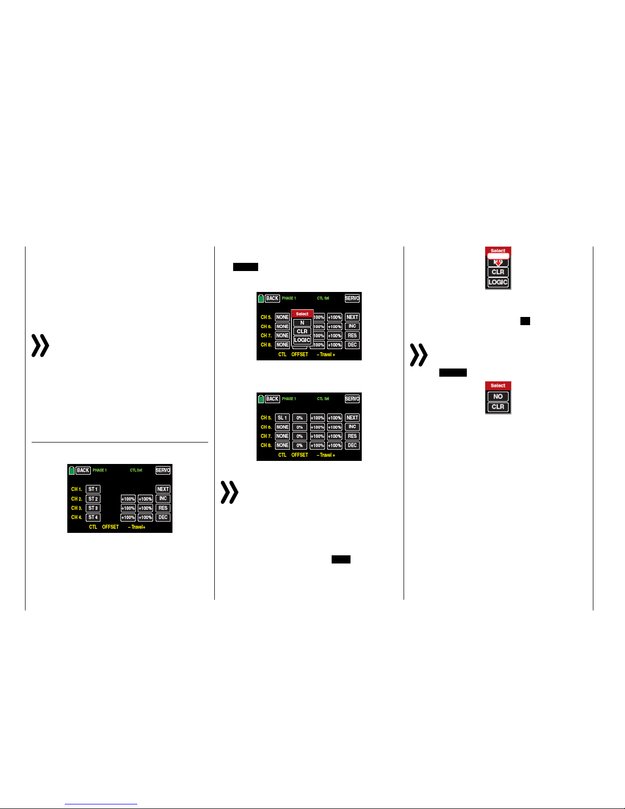
In the sub-menu "CTL Set" (control and switch assignment) you can …
… assign transmitter inputs 1 … 12 to operate servos of the mz-24 HoTT Pro transmitter as well as any
control stick (ST1 … ST4) and controls identified as
"DVx", "SLx" or "DTx", or any switch identified as "S1
… S8".
The following window appears in the display after touching the corresponding button, such as
the NONE button to the right of "CH 5" in the second
page of the display of this menu, with a finger or the
provide stylus, and the following window will appear:
Actuate the desired control (control stick 1 … 4, DV1
… DV4, SL1 … SL2, or DT1 … DT2) or switch (S1 …
S8), such as the right proportional rotary control SL1:
Note
The controls are only recognized after a specific
path. Therefore move the control to the left or
right, forward or backward until the assignment
appears on the display. If the length of travel is insufficient, move the control in the opposite direction.
Deleting controls or switches
After the switching or control assignment has been
activated as described, touch the CLR button.
touch
Control or switch assignment interruption
After the switching or control assignment has been
activated as described, touch the N button.
Notice
In few menu positions you can assign only physical controls or switches, that is the reason why in
the pop-up windows that appear in those posi-
tions the LOGIC button is not available, for example:
This is not an error.
26 Control and switch assignment
Page 27
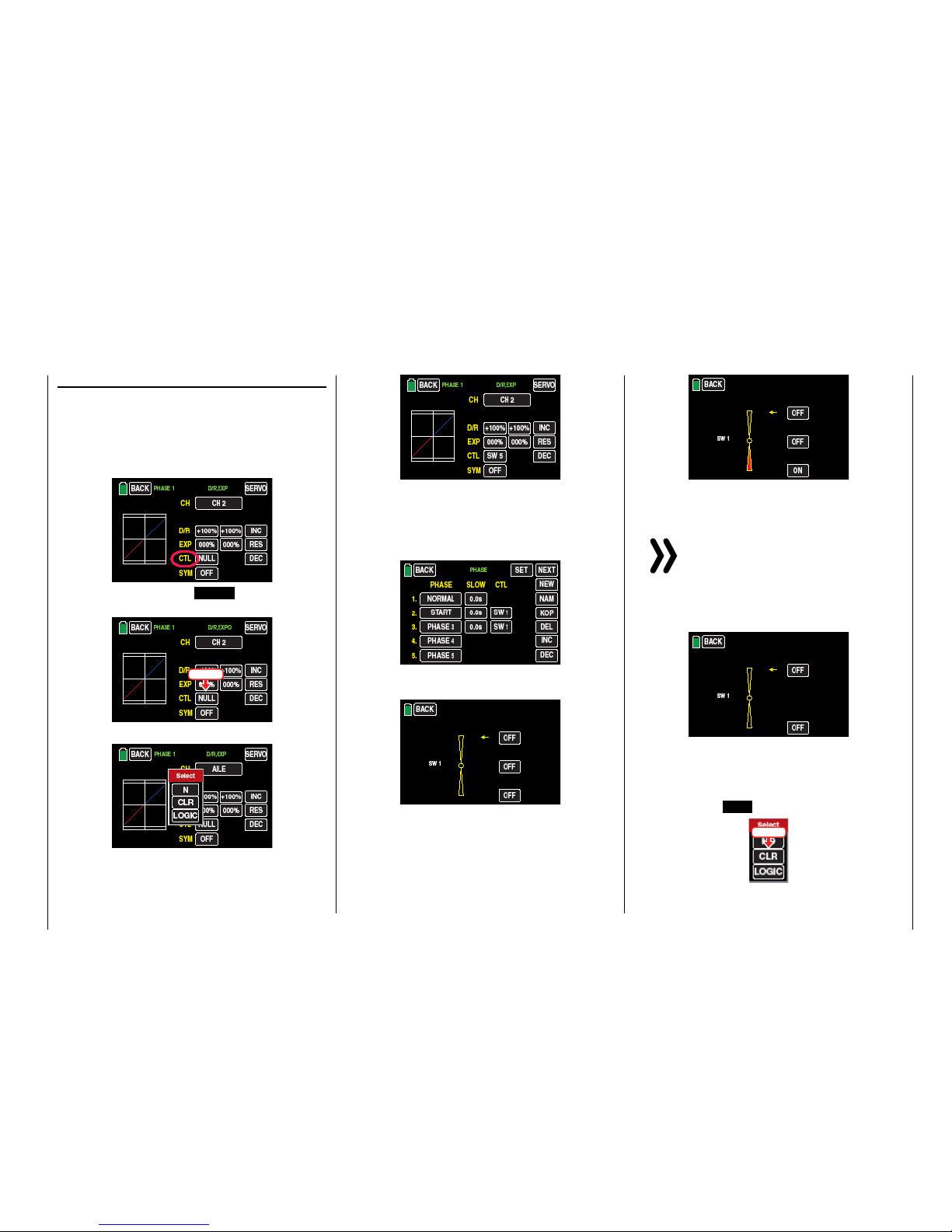
Assigning logical switch or control
• Switch assignment
The places in the program where a switch, a logical
control or switch can be assigned are marked with
"CTL". So as for example as marked with a red circle in the penultimate line of the following picture
of the Dual Rate / Expo displays:
As soon as you tap on NONE , on the right near
CTL …
touch
... the window in the display will ...
... appear. Actuate the desired switch, for example
the front left 3-way switch S5:
Thus completes the assignation of the switch for
this menu.
• Switch setup
In other menus, in which the switches can be assigned, for example the "PHASE" menu, …
... an accessory display will appear immediately after the switch assignation.
Completely independently from the yellow arrow,
which only indicates the actual position, you can
confirm in this display by touching the related button, in which position di selected phase should be
"ON", for example:
It has to be logically matched with the other switch
positions.
Notice
The phase 1, the "normal phase", is then always active when none of the assigned phase
switch is on the "ON" position.
If you choose the 2-stage switch SW 6 instead of
the 3-stage switch SW 1, the display appears as
follows:
Select the desired switching direction as above.
• Deleting switches
After the switching or control assignment has been
activated as described at the beginning of this section, touch the CLR button.
touch
27
Control and switch assignment
Page 28
Canceling the switch assignment
After the switching assignment has been activated as described at the beginning of this section,
touch the N button.
touch
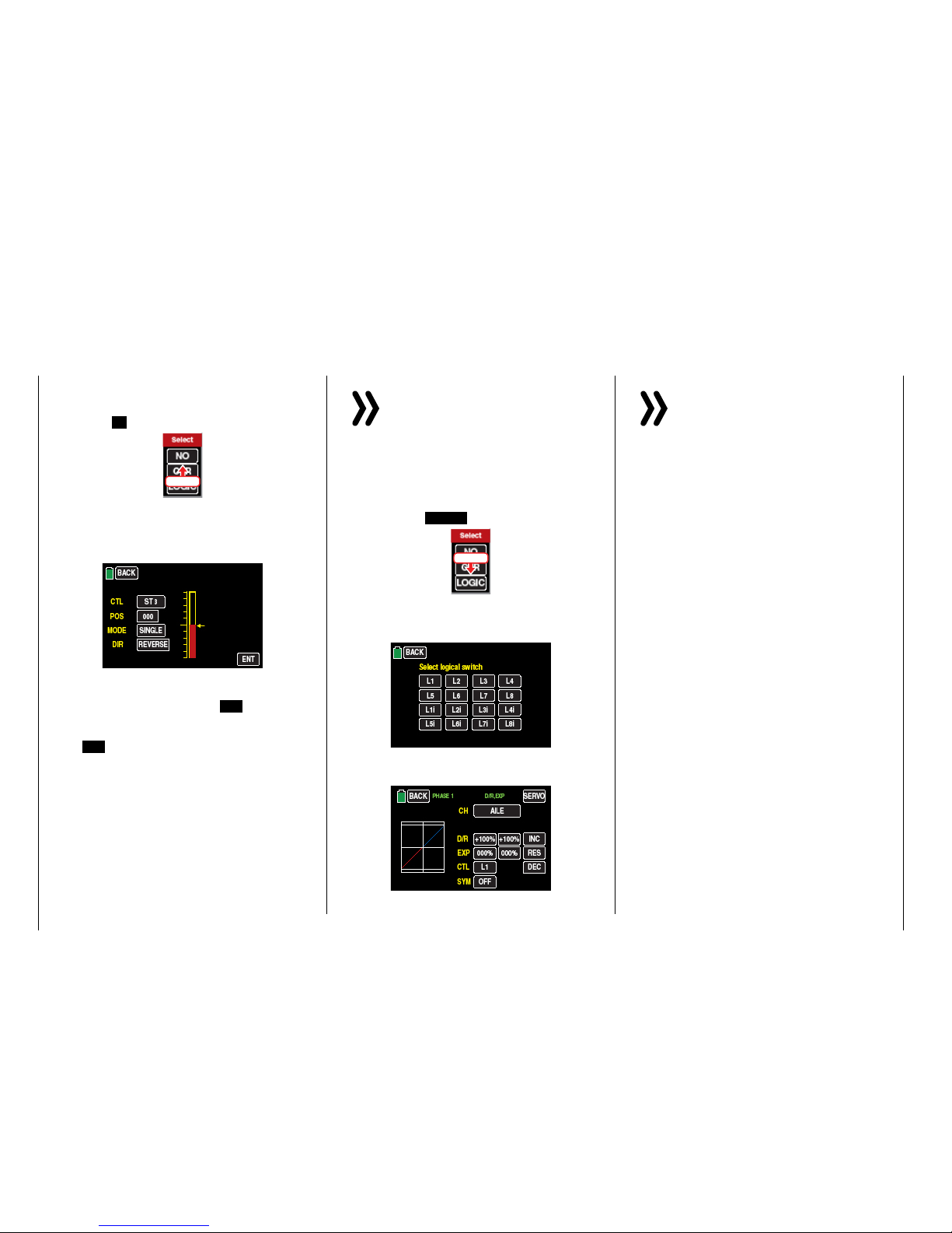
• Control switch assignment
Move the control that you want to use to activate
the switching function, for example the control
function 3, indicated with "SL2":
The yellow arrow to the right of the bar diagram
illustrates the current control position which can
be accepted by touching the ENT button as the
switching point in the value field to the right of
"POS". Reverse the switching direction by touching REV in the line "DIR(ection)".
In the "MODE" line, the switching function of the
control switch can be changed from on/off like
a 2-stage switch to the switching behavior of a
3-stage switch.
Notice
In this case, be sure to specify a switching position that is not "000". Otherwise, you risk
switching continuously back-and-forth between the two switching states while the relevant
control is in the middle control position.
• Assigning logical switch
After the switching or control assignment has been
activated as described at the beginning of this section, touch the LOGIC button:
touch
In the new window appears a list with the eight
logical switches "L1 ... L8" so as 8 inverted logical switches.
As soon as you tap on the desired switch, it will be
assumed in the output menu, for example:
Notice
Therefore do not forget to program the related
selected logical switch in the "Logical sw"
sub-menu!
Tips
Through the logical switches, see sub-menu "Logi-
cal sw", you can logically interconnect two switch-
es and/or also control switch in a "AND" or "OR"
switch.. A total amount of 8 logical switches "L1 ...
L8" (so as 8 accessory logical switches with reversed
switch direction) are available.
The result of one of these logical switch functions
can also be used as switch function in another logical switch. For more specific details, see the related
menu.
• All of these switches can be given multiple assignments. Make sure that you do not accidentally assign competing functions to a switch. It is recommendable to write down the switching functions.
Practical examples:
• Turning an on-board glow plug heater on and
offwhen a idling switching pointfor the THR control stick is exceeded or undershot. The switch for
the glow plug heater is controlled at the transmitter
by a mixer.
• Automatically turning the stopwatch on and off to
measure the actual flight time of a helicopter by
means of a control switch on the throttle limiter.
• Automatically turning off the mixer "AILE RUDD"
when the brake flap extends to adapt the landing
position of the model to the ground contour when
landing on a slope without affecting the direction
of flight by rudders which are otherwise involved.
28 Control and switch assignment
Page 29

• Extend the landing flaps and retrim the elevator
while approaching a landing once the throttle control stick is moved beyond the switching point.
• Turn the stop watch on and off to measure the operating time of electric motors.
• …
29
Control and switch assignment
Page 30
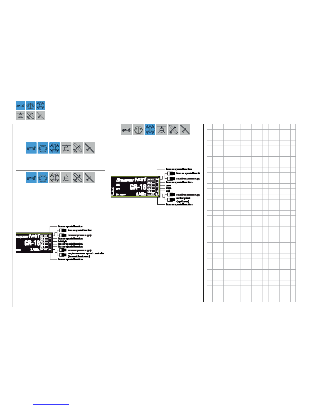
Receiver configuration
Vehicles, boats and copters
All of the relevant menus for the previously mentioned
model types are identified in the next section with at
least one of these three model characterizing "colored" symbols, ...
So that when you are programming you will only have
to concern yourself with the related menus.
Connection notices
For vehicle and boat models there are basically four
different ways of assigning the control functions forward/backward and left/right of both control sticks.
The options that are chosen depend on the individual preferences of the model pilot. The compatibility
with the Control modes 1 … 4 ways is however recommended, connect the control function 1 with the
forward/backward function and the control function 4
with the direction function:
Also for copters there are basically four different ways
of assigning the four control functions of roll, nick,
yaw and throttle/pitch of both sticks. The options that
are chosen depend on the individual preferences of
the model pilot. The compatibility with the Control
modes 1 … 4 ways is however recommended to take
the following occupation as example:
30 Receiver assignation
Page 31

Helicopter models
All of the relevant menus for helicopter models are
identified in the following "Program description” section with the symbol that characterizes this model
type...
... so that you only have to deal with these menus
when programming helicopter models.
Installation notices
Notice
The servos must be connected to the receiver in
the indicated sequence. Outputs that are not required are simply not assigned.
Follow the instructions on the subsequent pages.
Tip
In order to take advantage of the comfort and safety features of the "Thr.Limit", a governor should be connected
to receiver output "6" instead of receiver output "8" in
the adjacent receiver configuration. More information on
this subject can be found on page 161.
Receiver assignment for helicopter models ...
... with 1 to 3 swashplate servos
... with 4 swashplate servos
Notice
In comparison to the receiver configuration of
some older Graupner/JR transmitters, servo
connection 1 (pitch servo)and servo connection
6 (throttle servo) have been switched. The servos must
be connected to the receiver outputs as depicted on the
right. Outputs that are not required are simply not assigned.
More details on the swashplate typecan be found in
the menu "Model selection".
31
Receiver assignation
Page 32

All of the relevant menus for motor-powered airplanes
or glider models are identified in the next section with
at least one of these two model types characterizing
"colored" symbols, ...
... so that you only have to deal with the relevant
menus when programming fixed-wing models.
Installation notices
Notice
The servos must be connected to the receiver in
the indicated sequence. Outputs that are not required are simply not assigned.
Follow the instructions on the following pages.
Fixed-wing models with and without a motor with
up to 4 ailerons and up to 4 flaps ...
… and a normal tail unit or "2 elevator servos"
… and "V-tail"
Motor-powered airplanes and glider models
Delta/flying wing models with and without a
motor with up to 4 ailerons/elevators and 4 flap/
elevator servos
32 Receiver assignation
Page 33

Due to the different installation of the servos and rudder linkages, the operating direction for certain servos
can be reversed. The following table offers assistance
in this regard.
Model
type
Servo with wrong
direction of rota-
tion
Solution
V-Tail Reverse rudder and
elevator
Invert the servos 3
+ 4 in the sub-menu
"REV/SUB"
Rudder correct,
elevator reversed
Switch servos 3 + 4
on the receiver
The elevator is
correct,
rudder is reversed
Invert the servo 3 +
4 in the sub-menu
"REV/SUB" AND
switch them in the
receiver
Delta,
Flying
wing
Elevator and aileron
reversed
Invert the servos 2
+ 3 in the sub-menu
"REV/SUB"
Elevator correct,
aileron reversed
Invert the servo 2 +
3 in the sub-menu
"REV/SUB" AND
switch them in the
receiver
Aileron correct,
elevator reversed
Switch servos 2 + 3
on the receiver
33
Servo with wrong direction of rotation
Page 34

Program description
As already mentioned in section Operating the dis-
plays,you can touch one of the fourgear iconsat the
bottom right of the basic displayidentified with "B",
"F", "S" and T…
… to open the respective selection menu.
These sub menus contain all of the setting and display
menus required to program a model as well as the
transmitter.
The description of the individual menu items starting
on page 38 is offered in the sequence provided by
the transmitter.
Notice
The display screen-shots of this manual are intended for illustration purpose only. Therefore
please note that the represented settings and
setting values cannot be used for 1:1 reference.
"B“ ("green“ basis menu)
Touch the gear icon labeled "S" with a finger or with
the provided stylus:
This menu contains all of the base setting and display
menus that are needed to set up the model:
Name Menu Page
MOD.SEL. "Model Sel" 38
Model Type "Model type" 60
E.P.A "Servo path/servo limit" 62
REV/SUB
"Servo reverse/servo sub-
trim"
64
THT.CUT "Throttle Cut"* 66
TX ctl "Transmitter controls" 68
Timer "Timer" 74
Fail Safe "Fail Safe" 80
Trim Step "Trim step" 82
Servo "Servo monitor" 86
CTL Set "Control setting" 90
Out.Swap "Transmitter output" 96
Telemetry "Telemetry setting" 98
Announce "Announce" 118
"F" ("blue" function menu)
Touch the gear icon labeled "F" with a finger or with
the provided stylus:
Depending on the model type of the currently active
model memory, different menu structures are displayed. These can also vary depending on the basic
settings of the model. The following menu representations therefore only offer a selection as an example:
Name Menu Page
Phase "Phase setting" 120
D/R,EXP "Dual rate, Expo" 124
THR.CRV "Throttle curve" 128
Prog.MIX "Free mixers" 134
Trainer "Trainer system" 141
Logical sw "Logical switch" 148
Sequence "Sequencer" 150
For reasons of space the description of these "general
menus" in the next paragraphs will not be repeated because the sub-menus are contained also in the "blue"
menus of the model type "helicopter" and "airplane".
However, for major clarity, these "general menus" have
been integrated both in the Index and in the following
charts according to the sequence.
* hidden for models without a motor
34 Program description
Page 35

Name Menu Page
Phase "Phase setting" 120
D/R,EXP "Dual rate, Expo" 124
PIT.CRV "Pitchcurve" 154
THR.CRV "Throttle curve" 160
Gyr/Gover "Gyro/governor" 166
THR.HOLD "Throttle autorotation" 170
Swash "Swashplate mixer" 172
S.Limit "Swashplate limiter" 173
S.MIX "Heli mixer" 174
THR.MIX "Throttle mixer" 176
Prog.MIX "Free mixers" 134
Trainer "Trainer system" 141
PIT>>TAIL "Pitch >> tail mixer" 178
Logical sw "Logical switch" 148
Sequence "Sequencer" 150
Name Menu Page
Phase "Phase setting" 120
D/R,EXP "Dual rate, Expo" 124
THR.CRV "Throttle curve" 128
Idle LOW "Idlesetting"* 180
Prog.MIX "Free mixers" 134
Snap roll "Snap roll setting" 181
Aile diff "Aileron setting" 182
Wing MIX "Wing mixer" 188
Flap MIX "AILE and FLAP mix"** 192
Flap set "Flap setting"** 196
Airbrake "Airbrake settings"** 200
Trainer "Trainer system" 141
Logical sw "Logical switch" 148
Sequence "Sequencer" 150
V-Tail "V-Tail"** 206
* hidden for models with an electric motor
** Depending on the selected model type or hidden.
Name Menu Page
Phase "Phase setting" 120
D/R,EXP "Dual rate, Expo" 124
THR.CRV "Throttle curve"* 128
Prog.MIX "Free mixers" 134
Snap roll "Snap roll setting" 181
Aile diff "Aileron setting" 184
Wing MIX "Wing mixer" 188
Flap MIX "AILE and FLAP mix"** 192
Flap set "Flap setting"** 196
Butterfly "Butterfly"** 202
Trainer "Trainer system" 141
Logical sw "Logical switch" 148
Sequence "Sequencer" 150
V-Tail "V-Tail"** 206
* hidden for models without a motor
** Depending on the selected model type or hidden.
35
Program description
Page 36

"S" ("purple“ system menu)
Touch the gear icon labeled "S" with a finger or with
the provided stylus:
In this menu exclusively transmitter specific setting and display menus reassumed, excluding the
"WARNING" menus:
Name Menu Page
ST mode "Stick mode" 208
Warning "Warning instructions" 210
Etc. Set "Various settings" 212
Display "Display settings" 216
Stick Cali "Stick calibration" 220
MP3 "MP3 Player" 222
"T" ("Telemetry display“)
Touch the gear icon labeled with "T" at the bottom
right with a finger or with the provided stylus:
The display switches from the basic display to a dis-
play of the telemetry data such as:
36 Program description
Page 37

37
Personal notes
Page 38

Model selection
Edit model memories 1 … 30
Switch your receiver system and the RF module of
your transmitter off. Then touch the "M x" value field
line in the left side of the display with a finger or the
provided stylus in the basic transmitter display of the
transmitter:
Touch
... to change directly to the "Model select" sub-menu:
Or alternately touch the gear icon labeled "B" to open
the same sub-menu from the base menu:
Touch
• Until the transmitter is in Wireless trainer
mode, the access to the "Model select" sub-
menu is generally blocked.
Model type display
The name of the actually active model memory is
shown in the upper part of the display and the model type of the active model memory is indicated by
the icon right underneath. For example the model
type"Heli" of the active model memory 01 which is
named "STARLET":
Without starting a model change, that actual model
type can also be recalled by simply tapping on the
desired model memory, for example:
Touch
Notices
• If there is no reaction by tapping on the value
field M x in the base menu of the transmitter
or if after tapping on the "green" "Model se-
lect" icon, visible in the base menu, it appears
the warning message ...
• ... then there is still a connection between
transmitter and receiver. Switch the power
supply of the receiver off and try again:
38 Base menu - Model selection
Page 39

Touch
Tip
In the same way you can proceed for the display of the
model type in the "Import from SD card" option.
HoTT synchronization methods setting
As already mentioned in the paragraph "Starting up the
receiver", if both receiver and RF module are switched
off each preferred of the total 30 model memories of
the mz-24 HoTT Pro transmitter can be switched from
the standard memory specific HoTT-Synchronization
to transmitter specific and vice-versa. It is possible to
recognize the model memory with active HoTT-synchronization method from the yellow "G" which is displayed on the right near the selection button which is
near the model name.
WITHOUT "G" on the right
near the button = memory
specific bound
WITH "G" on the right near
the button = transmitter specific (global) bound
In the following representation the model memories
1, 2 and 3 are left as example on memory specific
HoTT-Synchronization and the memories 4, 5 and 6
have been switched to transmitter specific HoTT-Synchronisation.
Switching the HoTT-Synchronization
Switch the RF module of your transmitter off.
Tap on the actually in use model memory, for example
model memory 3:
Touch
The color of the field switches from black to blue:
Now tap on the model type icon, ...
Touch
... here it will appear a selection window, where the selection buttons are always indicated with the description of the method, through which you can switch. In
this example from memory specific to transmitter specific. Subsequently the button is actually described
with the synonym "GLOBAL" for transmitter specific:
Touch NO to terminate the procedure. Touching GLOBAL switches the selected model memory
to "global", that means transmitter specific HoTT-Synchronization:
39
Base menu - Model selection
Page 40

If you want to switch a model memory, which is actually set to GLOBAL, to model specific HoTT-Synchronization, then the selection button will appear with the
description MODEL:
Touch NO to terminate the procedure. Touching MODEL switches the selected model memory
back to model memory specific HoTT-Synchronization:
• As conclusion of the switching process for one or
more model memories all the involved receivers
must be bound again.
• "GLOBAL", then transmitter specific, bound receivers react to the signals of all of the global
bound model memories of "their" transmitter, this
explains why for safety reasons a model memory
change is only possible after switching off the receiver system!
CAUTION
A receiver system, switched on accidentally after a model memory change,
reacts to every control movements of
the model memory bound in global mode as
soon as a valid signal is emitted from "its"
transmitter.
• "MODEL" specific bound receivers react exclusively to the signal coming from the specifically
assigned model memory. An accidental use thorough a non specifically assigned model memory
is NOT possible. A receiver which has eventually
been switched on after a model memory change
will pass to the Fail-safe mode during all the time
in which the aforementioned situation lasts.
Tip
Information about HoTT-Synchronisation after copying
or exporting/importing a model memory can be found in
the related following section.
SW (page change)
Touch the SW button in the display at the top right to
switch, according to the rotation principle, from the
first six model memories...
Touch
... to a display of the next six...
… etc. After model memories 25 … 30 are displayed,
model memories 01 … 06 reappear for selection, etc.
SEL (change model)
Touch the selection field for the desired model memory, for example:
Touch
The color of the field switches from black to blue:
Tap on the SEL button on the right side of the display
…
40 Base menu - Model selection
Page 41

Touch
… and then touch NO to terminate the process or
YES to switch the model …
Touch
… "Please wait!!" appears for about 1 second:
• If a receiver is already bound to the selected model
memory, in case of inactive Thr.POS warning the
RF module of the transmitter will be switched on
and the display changes to the base display with a
warning window:
… or by touching the related BACK button until
you will be brought directly to the base display of
the transmitter.
NEU (create new model)
Tips
• To reach up for model memories with number
higher than 06, tap on the NEXT button on the
right upper side of the display (next page).
• You can change between already occupied model
memories through SEL .
As described above under SEL , to set up a new
model, select a free model memory or model memory that has already been assigned but is no longer
required. Tap on the NEW button on the right side of
the display:
Touch
After tapping on NEW a selection window will appear
in which you can select one option between manual
or assisted programming of the new model so as NO
to interrupt the procedure:
So as it happens when you switch the transmitter
on, you now have the option of waiting a few seconds until the display disappears automatically or
maintaining the RF transmissions by manually tapping the ON button, or switching them off by tapping the OFF button.
• If no receiver is bound to the selected model memory, the display also changes to the base display
with the visible window. The RF module remains
then switched off and in place of the "RF ON/OFF"
warning it will appear "No receiver bound to TX!":
Tapping on the SET button directly opens the
sub-menu »TX ctl« of the basis menu, where you
can bind your receiver in the line "Bind ON/OFF"
…
41
Base menu - Model selection
Page 42

To transfer the model name into the model memory,
touch the red button = [ENTER] at the bottom right:
Touch
Touch the MAN. button at the top left to go to the
next option:
Touch
In the following sub-menus, the options to configure
the required options will be proposed according to the
model type previously selected.
The sequence of the buttons for the manual programming referred to a fixed wing model will be explained
in the following sections.
Tip
Assistant-controlled model programming will be subsequently addressed with reference toprogramming a
helicopter.
Manually programming the basic settings of a
new model
Tap then on the MAN. button:
Touch
The manual, so as the assistant controlled, programming of a model follows always a program predefined
procedure which begins with the input of the model
name:
"Model name"
Switch between uppercase and lowercase and vice
versa with the CAPS button at the bottom edge of the
screen, and similarly, press the NUM button to go to
the numbers 0 … 9 and special characters.
Switch to the desired symbols chart and tap on the
first character of the model name.
To enter an empty space tap on the
[Space] button. You can select other special characters by touching the SPECIAL button.
All other characters can be entered in the same manner. A maximum of 15 characters can be entered for
a model name.
By touching < [DELETE] in the bottom row of red
buttons, the last character is deleted. To delete all of
the entered characters at once, touch << [CLEAR].
The characters which are entered in this manner
appear in the blue field above the keypad in the sequence in which they are entered, for example:
42 Base menu - Model selection
Page 43

"Model type"
Since at this juncture we want to program an "airplane with electric drive", touch the selection field
"MOT(motor model)":
Touch
After selecting the basic model type, the following appears in the display...
"Wing type"
... in which you can specify the number of aileron and
flap servos by touching the corresponding selection
field:
You can switch beforehand to the selection list for delta/flying fixed-wing models by touching the top button labeled Normal:
After you select a wing type, the following display appears...
"Tail type"
…, in which you can specify the type of your tail:
Finish your entry by selecting...
"Propulsion type"
... For your model:
Tip
The default for " Motor off" or "Idle" = "Rear thro position" canbe switchedto"Front thro position"for fixedwing models in the "Throttle curve" menu, by inverting
the controlcurve.
After the propulsion type has been selected, a display
appears with an overview of the previous entries such
as...
…, which you can leave to go to the base menu by
touching the ENT button at the right bottom:
43
Base menu - Model selection
Page 44

Entering the basic settings of a new model with
an assistant
The previous section described the basic manual
programming of a fixed-wing model. In the following,
the assistant-controlled programming of a helicopter
model will be described. As the manual programming,
also the assisted programming follows always a predefined program procedure.
Tip
Some of the following described sub-menus offer theoretically the possibility of phase-specific settings. Each
one indicated on the upper left side by the green colored
phase name "PHASE 1", for example:
Because within the assisted programming only settings
in the "Phase 1" (the normal phase) are possible, in this
context it will not be told much more about "phase specific settings". More about this point is explained in the
description of the single menu point.
As described under NEW in the section "Model se-
lection", to set up a new model, select a free model
memory or model memory that has already been assigned but is no longer required.
After tapping on NEW a selection window will appear
in which you can select one option between manual
or assisted programming of the new model so as NO
to interrupt the procedure:
In the following sub-menus, the options to configure
the required options will be proposed according to the
model type previously selected.
Since the programming of a helicopter with the help
of an assistant will be soon described in this section,
touch the WIZ. button:
Touch
Tip
An example of manual model programming is described
in the previous section in the context of programming a
fixed wing model.
As previously described with reference to manual
model programming, basic programming is started by
entering a model name when programming a model
with an assistant.
"Model name"
Switch between uppercase and lowercase and vice
versa with the CAPS button at the bottom edge of the
screen, and similarly, press the NUM button to go to
the numbers 0 … 9 and special characters.
Switch to the desired symbols chart and tap on the
first character of the model name.
To enter an empty space tap on the
[Space] button. You can select other special characters by touching the SPECIAL button.
All other characters can be entered in the same manner. A maximum of 15 characters can be entered for
a model name.
By touching < [DELETE] in the bottom row of red
buttons, the last character is deleted. To delete all of
the entered characters at once, touch << [CLEAR].
The characters which are entered in this manner
appear in the blue field above the keypad in the sequence in which they are entered, for example:
44 Base menu - Model selection
Page 45

To transfer the model name into the model memory,
touch the red button = [ENTER] at the bottom right:
Touch
Touch the WIZ. button at the top left to go to the next
option:
Touch
"Model type"
Since at this juncture we want to program a "helicopter model", touch the Heli button:
Touch
After selecting the basic model type, the following appears in the display...
"Swashplate type"
... in which you can specify the number of swashplate
servos by touching the corresponding selection field:
• "1 Servo"
You are using a flybar system, or the swashplate is
tilted by a roll and nick servo. One separate servo
is used for the pitch control.
(Since helicopter models with only one pitch servo
that have three swashplate servos for pitch, nick
and roll also operate without a mix of functions in
the transmitter as is usually the case with flybar
systems, the menu item "Swash", page , normally
does not appear on the multifunction menu.)
• "2 Servo"
The swashplate isshifted axially for the pitch control by means of two roll servos; the nick control
isdecoupled by means of a mechanical compensation rocker.
• "3Sv (2Roll)"
Symmetrical three-point control of the swashplate by means of three articulations pointsoffset
by 120°, by means of which one nick servo (front
or rear) and two roll servos (to the left and right
side) are connected. All of the three servos of the
swashplate shift axially for pitch control.
• "3Sv (140)"
Asymmetrical three-point control of the swashplate by means of three articulations pointsoffset,
by means of which one nick servo (rear)and two
roll servos (to the left side and right front) are connected. All of the three servos of the swashplate
shift axially for pitch control.
45
Base menu - Model selection
Page 46

Notices
• The possibility to reverse the direction of the
servos connected to the output 6 (C6) in a
helicopter model and the output 1 (C1) in the
other types is only offered to match with the
different building cases. Otherwise the switchon warning will react not properly. For this reason a change in the value field is only possible
after confirming the "SURE?" warning.
• Independent of trim controls and any mix
settings, the neutral position can be shifted
around ±125% within the maximum servo
travel of ±150%. The servo is always adjusted
directly independent of all other trim and mix
settings.
Note that if the neutral position is adjusted strongly, servo travel on one side
may be restricted
since the total travel
is limited to ±150%
for electronic and
mechanical reasons.
Tap on the WIZ. button at the top left to go to the next
option ...
• "3Sv (2Nick)"
Symmetrical three-point axis as before, but rotated 90°; one roll servoon the side, and twonick
servos, front and rear.
• "4Sv (90)"
Four-point control of the swashplateby means of
two roll servos and two nick servos.
Directly after you make your swash plate selection,
the following display appears ...
"Propulsion type"
... where you specify whether your helicopter is driven
by an electric motor or ICE engine:
After you select the propulsion mode, the assistant
takes you to the first model-dependent settings in the
following display...
"REV/SUB" (Servo reverse/Servo sub trim)
Tip
In order to set control channels with numbers higher
than CH6, touch NEXT [change page].
In this display you can set on the left column the directions and on the right column the neutral positions
of each servo phase specific by tapping on the related
button, for example in the second display page to find
the servo 8:
Touch
46 Base menu - Model selection
Page 47

"E.P.A." (Servo travel/limit)
Tip
In order to set control channels with numbers higher
than CH6, touch NEXT [change page].
The travel and limitation are shown separately for
each side in this display. The setting range in both
cases is 0 … 150% of the normal travel.
The set values always refer to the settings in the submenu "REV/SUB".
To change a current value, touch the desired option
field, for example:
Touch
The selected option field will be marked in blue:
Touch the + button at the right edge of the display to
gradually increase the value of the active option field.
Touch the – button underneath to reduce the current
value of the active option field, and touch the RES
button to reset the changed value back to the default.
Once all you have adjusted all of your servos, touch
the WIZ. button at the top left to switch to the next
adjustment phase:
"D/R,EXP"
The dual rate/expo function allows you to switch or
influence the control deflections and characteristics
for the control functions of roll, nick and tail rotor, i.e.
control functions 2 … 4 through switch.
Dual Rate acts, as the control setting in the submenu "Ctl.SET", directly on the related Control func-
tion, independently from the fact that the function is
associated to a single servo or i actuated thorough a
complex mixer or coupling function by many different
servos.
The control deflections can be set for each switch
position between 0 and 125% of the normal control
travel.
EXP allows a more sensitive control of the model in
the central position of the respective control function
(roll, nick and tail rotor) for values greater than 0%
without having to do without the complete deflection
in the end position of the control stick.
Conversely, the effect of the control around neutral
position increases for values less than 0% and decreases in the direction of the full deflection. The progression can be set from -100% to +100%; 0% corresponds to the normal linear control characteristic.
The EXP setting always acts directly on the corresponding control function independent of whether
it affects the individual servo or several servos by
means of complex mixing and coupling functions.
By default, the dual rate and/or expo values are set for
each control side. After switching the option "SYM"
from OFF to …
Touch
... to ON, a symmetrical, that is joint, setting of both
control sides is possible.
In the graphic of the display, the curve characteristics
are shown directly.
Tip
After having completed the program assisted model programming and the setting of the phases in the "PHASE"
sub-menu of the functions menu all the options contained in the Dual rate/Expo phase specific menus can
be programmed.
Programming
Between the setting displays of individual control
functions, alternatively touch the button on the right
near the yellow "C" (channel) with a finger or the provided stylus:
47
Base menu - Model selection
Page 48

Touch
Analogous to the previously described displays, touch
the corresponding option field to change a current
value, and raise or lower the value by touching the +
and – buttons at the right side of the display the appropriate number of times.
The adjustment range is ±125 % in the "D/R" line and
±100 % in the "EXP" line.
Touch the RES button to reset a changed value in a
blue (active) value field to the default value.
If you desire a switch between two variants, you can
assign a switch or a control in the CTL line, as described in the "Control and switch assignment" paragraph.
Once all you have adjusted all the DR/EXPO functions, touch again the WIZ. button at the top left to
switch to the next adjustment phase:
"Pitch curve"
In the "PITCH MIN." line of this display you can adjust to your preferences the movement direction of the
pitch stick so as, through the remaining options, the
pitch curve.
1. Line "PITCH MIN."
Through this option you can easily reverse the
control direction of the pitch control stick from
the standard pre-set position "pitch min back" to
"pitch min forward", and vice versa, by tapping on
the BACK or FORWARD button in the "Pitch min"
line:
Touch
After tapping on this button it will appear a safety query:
Touch NO to terminate the procedure. Tapping
on YES confirms the procedure and reverses the
movement direction of the pitch stick WITHOUT
any visual changes in the display:
2. Setting the pitch curve
Tip
After having completed the program assisted model
programming and the setting of the phases in the
"PHASE" sub-menu of the functions phase specific
menus can be programmed.
Basic operating steps
• Button ST OFF / ST ON
Touch this button to turn the graphic and numeric display of the control stick position on
and off, for example:
With the control element (gas/pitch control
stick), a vertical green line is moved synchronously in the graph between the two endpoints
"L" and "H". The momentary control stick position is also displayed numerically in the line
"IN"(put) (-100 % to +100 %). The intersection
of this line with the curve is identified as "OUT"(put) and can be varied at the support points
between -125% and +125%. The control signal which is changed in this way then affects all
of the following mixing and coupling functions.
• ENT button
Touch the button at the bottom right of the display to set up to 5 additional points between
the two endpoints "L" and "H".
In the following example, the control stick is exactly between the middle and end of its path,
at +50% of the control path, and generates an
output signal that is also +50% due to the linear characteristic.
48 Base menu - Model selection
Page 49

Once the support point number appears along
with the associated value in the line "POINT"
and the point is red (see the screen-shot below), you can delete it by touching the ENT
button, for example:
Touch
Changing the support point value
• X-axis button (X-axis)
Activate this function by touching the button
at the bottom edge of the display.
You can then move an active (red) point to
the right with the + button, and to the left
with the – button, for example:
Touch the X-axis button again to deactivate
the function.
Tips
• If you move the red pointhorizontally away
from thecurrentcontrol position, the point
becomesgreen after a short while, and a
"?" appears in the Point line. This question
mark does not relate to the point which
has been moved but rather indicates that
another point can be set at the current
control position.
• Remember that the percentages in the
"IN"(put) and "OUT"(put) line always refer
to the momentary position of the control
stick and not to the position of the point.
• Y-axis button (Y-axis)
Activate this function by touching the button
at the bottom edge of the display.
You can then move an active (red) point to
the top with the + button, and to the bottom
with the – button, for example:
Touch the Y-axis button again to deactivate
the function.
Between the two endpoints "L" and "H", up to
5 additional support points can be set, and the
distance between neighboring support points
may not be less than approximately 25%.
Move the control stick. As long as a ? is next to
the "POINT", you can set the next support point
by touching the ENT button. At the same time,
the "?" is replaced with a number:
The sequence in which the up to 5 points between the end points "L" and "H" are generated does not matter since the support points are
automatically renumbered sequentially from left
to right after one support point is set or deleted, for example:
Deleting a support point
In order to delete the set support points 1 to 5,
move the vertical line with the control stick next
to the relevant support point.
49
Base menu - Model selection
Page 50

Then press the desired control such as the
right proportional rotary control SL1:
• "MIXER" column
In the six value fields of the second column
with the header "MIXER", you can select individual helicopter mixers, or one of the two
available mixers in any combination.
To select a mixer, touch the button in the
"MIXER" column in the desired line with a
finger or the provided stylus, for example:
Touch
The button color changes from black to blue:
Tip
Remember that the percentages in the "IN"(put)
and "OUT"(put) line always refer to the momentary position of the control stick and not to the
position of the point.
Rounding off the throttle curve
• ON/OFF button in the "Curve" line
The default angled curve profile can be automatically rounded off by turning on the
rounding function by pressing this button,
for example:
Touch
Notice
The curves portrayed here are for demonstration purposes only and do not represent real pitch curves.
• TRIM button
The mz-24 HoTT Pro transmitters has a function that is integrated in the helicopter program
for trimming up to six support points of the
two options "throttle curve" and "pitch curve"
during flight though the transmitter software.
Open the following window by touching the
TRIM button at the top right edge of the dis-
play:
Basic operating steps
• "CTL" column
In the first column of the menu with the
heading "Control", select a control that appears suitable for this purpose from the controls offered by your mz-24 HoTT Pro transmitter.
In order to assign a control, touch the button in the "CTL" column and the desired line
with a finger or a provided stylus, for example:
Touch
The following appears in the display:
50 Base menu - Model selection
Page 51

Select the desired point L, 1 ... 5 or H in the
actually blue, then active, value field by tapping on the + or – button which are located on the right side of the display, for example:
Touch the RES button to reset a changed
value in a blue (active) value field to the default value.
Notice
The associated controller does not
have any effect ifan undefined point is
selected (in the basic version of the relevant curve mixers, only the points "L" and
"H" are set).
Select the desired mixer in the actually blue,
then active, value field by tapping on the +
or – button which are located on the right
side of the display, for example:
Touch the RES button to reset a changed
value in a blue (active) value field to the default value.
• "POINT" column
You have selected one or more mixers in the
lines of the "Mixer" column. In the "POINT"
column, specify the support point(s) to be
trimmed.
To select a point, touch the button in the
"POINT" column in the desired line with a
finger or the provided stylus, for example:
• "PHASE" column
If you want to, specify in the right "PHASE"
column the programmed phases in which
the governor should be active. In the value
field, in the example, "1 (normal)", the number refers to the phase number that can be
found in the sub-menu "PHASE".
To select another phase than default Phase1,
touch the button in the "Phase" column in
the desired line with a finger or the provided
stylus, for example:
You can change the current Phase number
in the blue (active) value field by touching
the + or – buttons at the right edge of the
display the desired number of times, for example:
Touch the RES button to reset a changed
value in a blue (active) value field to the default value.
51
Base menu - Model selection
Page 52

Notice
The settings that appear in this displayaffect the same records as those at a com-
parable location in the "TRIM" display of
the "THR.CRV" sub-menu (see next column)
which is why changesalwaysaffect each other.
After you finish making your settings, touch the
WIZ. button at the top left of the display to leave
this menu and go to "Pitch curve":
Touch
Touch the WIZ. button again in the "Pitch curve" display …
Touch
… To leave the assistant and to open the next submenu ...
"Throttle curve"
The throttle curve can be specified by up to 7 points,
the so-called support points, along the entire control
stick travel:
Support points can be set, changed and deleted in
the same manner as described in the previous section, "Pitch curve". First specify the throttle curve using three points, that is, the two end points "L" and
"H", as well as the other set point "1" in the control
center in order to harmonize the motor performance
curve with the pitch curve.
Tip
The value shown in the top left "throttle limit" line indicates basically the status or the position of the throttle
limit.
Further information about setting throttle curves can
be found in the description of the THROTTLE CURVE
menu.
Notice
The associated controller does not have any effect ifan undefined point is selected (in the basic
version of the relevant curve mixers, only the
points "L" and "H" are set).
Tips
The settings that appear in this display affect the
same records as those at a comparable location in
the "TRIM" display of the "Pitch curve" sub-menu
which is why changesalwaysaffect each other.
• After having completed the program assisted model
programming and the setting of the phases in the
"PHASE" sub-menu of the functions phase specific
throttle curves can be programmed.
Touch the WIZ. button in the "Throttle curve" display
to leave the assistant and open the next sub-menu: ...
"Gyr/Gover" (Gyro/Governor)
Within this display, you can make initial basic settings
as needed for your gyro and/or for any governor that
is used in your model.
Tip
After having completed the program assisted model programming and the setting of the phases in the
"PHASE" sub-menu of the functions menu all the options contained in this menu all the phase specific values
can be programmed.
52 Base menu - Model selection
Page 53

• "Gyro Suppression" line
Notice
This option maynormally not be used for current standard gyro systems. You therefore
need to consult your gyro setting instructions
since otherwise you may make it impossible to fly
your helicopter. Nonetheless, this sub-menu was retained to satisfy all requirements and conventions.
This option can influence the effect of the gyro
sensor (gyroscope) as the tail rotor control stick
is moved, assuming that a gyro system is used in
which the gyro's effect can be set by the transmitter using an additional channel, channel 7 in the
Graupner remote-control system. The gyro sup-
pression reduces the gyro's effect in a linear manner in proportion to the deflection of the tail rotor
control stick corresponding to the set value. If the
gyro has not been suppressed (at a value of 0%),
the gyro's effect remains independent of the control stick deflection.
The gyro's effect can however be additionally varied smoothly between a minimum and maximum
using a control assigned in the "Gyro" line in the
"CTL Set" menu, for example with one of the proportional dials DVx. More on this subject can be
found in the section "Gyro/governor".
• "Gyro Gain" line
Most of the current gyro systems can be adjusted for a smooth, proportional effect; you can also
choose between two different modes of action by
the transmitter.
If the gyro that you are using also has one of these
options, the alternative offset setting enables both
the normal gyro gain and "heading lock mode" as
well as flying with maximum stabilization in normal,
slow fights within this selected mode, and reducing the gyro gain in fast roundtrips and aerobatics.
Values up to ±125% are possible, for example:
Based on these phase specific settings (offset) the
gyro gain can also be proportionally varied with a
control assigned in the line "C7" in the sub-menu
"CTL Set", as for example the proportional dial
DVx.
Attention
• You therefore need to consult your gyro
setting instructions since otherwise you
may make it impossible to fly your helicopter.
• Note that the offset values enteredin this
optionas well as in the line "CH 7" of the
sub-menu "CTL Set" add up! For the
sake of clarity, make sure to only enter or
change an offset value in one of the two
options.
• "Governor ACT" line
In contrast to speed controllers that only regulate
performance like a carburetor, governors maintain
a constant speed in the system that they are monitoring by independently regulating the provided
output. Like the cruise control in cars, a governor
controls in case of ice engine helicopter the throttle servo in the same way as the speed controller
of an electric motor helicopter. Governors there-
fore only require a speed setting and not a classic
throttle curve. A deviation from the set speed oc-
curs when the required output exceeds the maximum available output.
To change the current value, touch the desired
button in the "Governor ACR" line. The display
switches from "OFF" to "ON" and vice versa, for
example:
• "Governor RATE" line
In the "GOVERNOR" line, in case you have
switched on the function "Governor at CH8". In the
"Governor RATE" line, enter the appropriate offset
value for the desired rotor speed. The value to be
set depends on the governor that is used as well
as the desired target speed, and can of course be
varied for specific phases, for example:
53
Base menu - Model selection
Page 54

With a control assigned in the "C8" line of the submenu "CTL Set", for example the proportional dial
DVx, this value can also be proportionally varied.
Touch the WIZ. button in the "Gyr/Gover" display
to leave the assistant and open the next sub-menu
...
THR.HOLD
During competition, is expected that gas engines
should be completely turned off. In the training phase,
this is a bit inconvenient since you would have to restart the engine after each autorotation training landing.
Therefore make the appropriate settings during the
training phase, as fully described in the THR.HOLD
paragraph, in this display so that the gas engine can
be kept idling during the autorotation phase without
the clutch engaging, or so that any electric drive is
definitely off, for example:
Tip
With the ""Throttle Cut"*" option in the Base menu,
there is an alternative emergency off function.
Touch the WIZ. button in the "THR.HOLD" display
to leave the assistant and open the next menu, for
example ...
…, which you can leave to go to the base menu by
touching the ENT button at the right bottom:
IMP.M (import from SD card)
Once a memory card is in an operational transmitter,
a blue memory card icon appears at the top right of
the basic display:
In the "Model Sel" sub-menu described here...
... you can import compatible models into the transmitter memory from the memory card inserted in the
transmitter's card slot.
For this reason, from the list of empty model memories offered in the "Model Sel" display, first select one
that appears appropriate, such as model memory 4
which is still available in this example. Touch the field
on the right adjacent to the yellow 04 with a finger
or the provided stylus. The color of the field switches
from black to blue:
54 Base menu - Model selection
Page 55

Once the process is completed, all the warning messages will disappear, and the display returns to the list
of models and the transmitter:
Tips
If a memory specific bound (and at the same time
assigned to the SD card, eventually for safety reasons) model is loaded again on the originally model
memory of the same transmitter, the receiver binding
will always be functional.
If, in contrast, the same model is copied in another
model memory or in a completely different transmitter, the receiver MUST be bound again to the transmitter.
• If a transmitter specific bound (and at the same time
assigned to the SD card, eventually for safety reasons) model is loaded again on another model memory of the same transmitter, the receiver binding will
always be functional.
If, in contrast, the same model is copied in another
transmitter, the receiver MUST be bound again to the
transmitter.
changes accordingly and on the right near "ORIGIN"
appears the number of the memory to import in red
characters:
Tip
The recall of each model type of the models saved
on the memory card is performed as described under
"Model type display".
Touch NO to terminate the action and return to the
start page. After tapping on YES …
Touch
… after a short while the message "Please Wait!" appears …
... while the selected model is imported into the selected mode memory.
Then switch to the display of the data model saved
on the SD card by touching the IMP.M button in the
middle of the right column:
Touch
Touch the model to be imported from the SD memory
card, for example:
Touch
The color of the field switches from black to blue.
At the same time the display of the model type icon
55
Base menu - Model selection
Page 56

EXP.M (Export to SD card)
Use this option to export models saved in the transmitter to a memory card inserted into the transmitter's
card slot. The binding information of the exported
model memories remain included.
Tip
Information about HoTT-Synchronisation of a model
memory after importing from an SD card can be found
in the precedent pages, in the notices under IMP.M.
Once a memory card is in an operational transmitter,
a blue memory card icon appears at the top right of
the basic display:
In the "Model Sel" sub-menu described here...
... you can export assigned model memories as desired to the memory card inserted in the card slot of
the transmitter.
Select the desired model memory, as for example the
model memory 02, from the list offered in the "model
sel." display. Tap on the field with the selected model
name. The color of the field switches from black to
blue:
As next, tap on the EXP.M button on the right side
of the display …
Touch
Additional information and buttons appear at the bottom right.
Touch NO to terminate the action and return to the
start page. After tapping on YES …
Touch
… after a short while the message "Please Wait!" appears …
… while the selected model is being exported to the
SD card.
Once the process is completed, all the warning messages will disappear, and the display returns to the list
of models and the transmitter:
56 Base menu - Model selection
Page 57

RES (delete model)
In the "Model Sel" sub-menu described here...
… you can reset an assigned model memory using
the RES button at the right edge of the display.
Select then the desired model memory in the list offered in the "Model Sel" display, as for example the
model memory 02, by tapping on it. The color of the
field switches from black to blue:
Tap on the RES button on the right side of the display:
Touch
Additional information and buttons appear at the bottom right.
Touch NO to terminate the action and return to the
start page. After tapping on YES …
Touch
… after a short while the message "Please Wait!" appears …
... while the selected model is being initialized.
Once the process is completed, all the warning mes-
sages will disappear, and the display returns to the list
of models and the transmitter:
If you have initialized not a "different" but the actually
in use model memory, after the end of the initialization
two note windows will appear:
Tapping on OK opens directly the "TX ctl" menu,
where you can bing again your receiver. The note "Fail
Safe not set" should remind you that no fail safe has
been set yet.
Tapping on NO terminates the process and brings
you back to the base menu.
Notice
This deletion cannot be restored. All of the data in
the selected model memory are completely deleted.
57
Base menu - Model selection
Page 58

CPY (copy model model)
In the "Model Sel" sub-menu described here...
… using the CPY button at the right edge of the display, you can copy an assigned model memory to any
other model memory.
Tips
• If a memory specific bound model is copied in another model memory of the same transmitter, the receiver must be bound again in the target model memory.
• If a transmitter specific bound model is loaded on
another model memory of the same transmitter, the
receiver binding will always be functional.
Select then the desired model memory in the list offered in the "Model Sel" display, as for example the
model memory 02, by tapping on it. The color of the
field switches from black to blue:
Tap on the CPY button right on the bottom:
Touch
Additional information and buttons appear at the bottom right.
Touch the desired target memory. The color of the selected field switches from black to blue, and the number of the selected target memory appears in red next
to "Target" in the blue field, for example: 05:
Touch NO to terminate the action and return to the
start page. After tapping on YES …
Touch
… after a short while the message "Please Wait!" appears …
... while the selected model is being copied to the target memory.
Once the process is completed, all the warning messages will disappear, and the display returns to the list
of models and the transmitter:
To go to the "Home menu", leave the "Model select"
display by touching the BACK button at the top left:
58 Base menu - Model selection
Page 59

Touch
59
Base menu - Model selection
Page 60

In the delivered form the transmitter the model selection display looks for example like this:
Normally, the basic type of model is specified when
creating the model memory in the sub-menu "Mod-
el selection" of the base menu. In the "Model Type"
sub-menu, you can directly change the type of the
current model. When such a change is made, all of
the mixers, coupling functions, etc. for the previous
model type are also deleted or at least need to be
adapted to the changed type.
Notice
Once you change any of the existing settings, all
of the relevant parameters are reset.
Programming
For example, the model memory 01 already used for
an helicopter has to be reprogrammed in the model
type "motor model". So Tap the first of the fields to be
changed, in this example, the key of the model underlying programming model type:
Model type
Change the model type
Touch
Touch
As described in detail in the section "Manually pro-
gramming the basic settings of a new model", the
manual configuration of a model memory starts with
a safety query:
Touch NO to terminate the procedure. Touching OK
will cause a change of the color of the OK button for
about 1s. Afterwards the model type selection is available.
Following the example, touch the central button labeled "HELI" in this display...
Touch
... the display then switches to the selection of the
next option...
Switch your receiver system and the RF module of
your transmitter off. In the basic transmitter display,
use your finger or the provided stylus to touch the
gear icon labeled "B" to accede into the base menu:
Touch
The display switches to the "green" base menu. Touch
the menu item "Model Type".
Touch
If after touching the "MODEL TYPE" icon in stead of
the awaited menu it appears the warning message …
... then there is still a connection between transmitter
and receiver. Switch your receiver off and try again.
60 Base menu - Model type
Page 61

... etc. For the remainder of the process, you only
need to use the assistant as described in the mentioned section until all the basic settings of the newly
selected model type are entered.
Basically, use the same procedure as you would, for
example, to change the wing type of the current model from "1AILE" to "2AILE 2FLAP'. In this case tap on
the button under "Wing Type" ...
Touch
... and change the wing type in the display "Wing
Type" that appears...
... by touching the desired "new" wing type. Use the
same procedure for all of the selectable fields.
The entire process is concluded by touching the ENT
button at the lower right side of the display which resumes all the selected options, for example:
Touch
Notices
• In the model type "BOAT", the only possible
selection is basically between motor powered
or non motor powered model type:
• In the model type "CAR" and "COPTER", the
only possible selection is basically the model
type:
61
Base menu - Model type
Page 62

In the basic transmitter display, use your finger or the
provided stylus to touch the gear icon labeled "B":
Touch
The display switches to the "green" base menu. Touch
the menu item
"E.P.A".
Touch
E.P.A. Setting
In this display, the parameters are set that exclusively
relate to the servo, that is the servo path and angle of
rotation or its limit.
The set values always refer to the settings in the submenu "REV/SUB".
E.P.A
E.P.A. Setting
Tip
In order to reach control channels with numbers higher
than CH5, touch NEXT [change page] at the top right
of the display.
To change a current value, touch the desired button,
for example:
Touch
The button color changes from black to blue:
Repeatedly touch the + button at the right edge of
the display to gradually increase the current value,
and touch the – button to lower the value in the active
value field. Touch the RES button to reset a changed
value back to the default value.
Use the same procedure for all the other settings.
To recall the graphic display of the servo travels of
the "Servo" menu (servo monitor) and to activate
the "Servo test" function integrated in this display by
touching the TEST
I field, tap on the SERVO button
on the top right side of the display or push the
buttons on the left of the display, at the same time,
while no value field is active:
Touch
Touch
Once you activate one or more control elements of
your transmitter, the resulting servo travel is graphically displayed, for example:
To go to the "BASE menu", leave the "Servo display"
by touching the BACK button at the top left:
62 Base menu - Servo path/Servo limit
Page 63

Notice
In contrast to the "CTL Set" sub-menu, all the
settings of this sub-menu refer to the relevant
servoindependent of where the control signal for
the servo comes from , i.e., either directly fromthe control element orfrom mix functions.
Example
The rudder servo of a model is directly controlled by the
rudder control stick and also through an accessory "Aileron Rudder" mixer. For model-specific reasons, this
servo can only follow a maximum servo travel of 100%
since for example the rudder would contact the elevator
if the allowed mechanical travel was more than 100%.
As long as only the rudder is used, this is not a problem.
It becomes a problem, however, if the signals add up to
a total travel of more than 100% when simultaneously
using the rudder and the aileron. The linkages and servos can be subject to an extreme load...
To prevent this, the path of the relevant servo has to
be limited individually. In the case of the rudder servos
used here as an example, this would be slightly less than
100% since we are assuming that the rudder is already
traveling 100%.
63
Base menu - Servo path/Servo limit
Page 64

In the basic transmitter display, use your finger or the
provided stylus to touch the gear icon labeled "B":
Touch
The display switches to the "green" base menu. Touch
the menu item
"REV/SUB".
Touch
REV/SUB
Setting of the servo direction and neutral position
Servo direction and neutral position
In both these displays in the left column can be set
the direction of each servo and in the right column the
related neutral position.
Notices
• First of all start by setting basically the direction in which the servos have to move before
you start setting other parameters!
• The numbers for the servos refer to the servos
connected to the corresponding receiver outputsproviding that thetransmitter and receiver outputs have not been switched. A change
in the control mode therefore does not influence the numbering of the servos.
1. Setting the servo direction
With this option, the direction of servo rotation is
adapted to the specifics in the particular model so
that, when the control linkages and articulations
are installed, the servo's rotational direction does
not have to be considered.
The direction of travel is reversed by touching the corresponding value fields labeled NOR
and REV, such as:
As soon as the travel direction of CH6 in a helicopter model type or CH1 in the other model types is
going to be changed, a warning will be displayed:
Touch NO to terminate the procedure. Touch YES
to confirm the procedure which changes the direction of travel of the servo connected to CH1 or CH
6.
64 Base menu - Servo reverse/Servo center
Page 65

Notice
In no case you should use the possibility of the
servo reverse of the channel 6 for helicopters and
channel 1 for other model types to reverse the
direction in which the related control stick works, only
use this possibility for situation adaptation. Because the
switch-on warning "CH1-Pos" as the "Thr.HOLD" function do not follow this kind of reverse control direction.
To reverse the control direction use exclusively the possibility offered by the "Pitch curve" menu for helicopters
models and "Throttle curve" for all the other model
types.
2. Setting of the neutral position
The servo middle position is for adapting servos
that are not standard (servo middle position with
a pulse length of 1.5 ms or 1500 μs ) as well as
for minor adaptations, for example fine adjustment
to the neutral position of control surfaces on the
model.
Independent of trim controls and any mix settings,
the neutral position can be shifted around ±125%
within the maximum servo travel of ±150%. The
servo is always adjusted directly independent of all
other trim and mix settings.
Notice
Note that if the neutral position is ad-
justed strongly, servo travel on one side may
be restricted since the total
travel is limited to ±150%
for electronic and mechanical reasons.
Notice
Move the trim control into the middle position
before changing the middle values.
Programming
To change the neutral position of a specific servo,
touch the corresponding button, for example:
Touch
The button color changes from black to blue:
Change the desired value by touching accordingly the + or – buttons on the right to the outside,
for example:
Touch the RES button to reset a changed value in
the blue field back to the default.
To recall the graphic display of the servo travels of
the "Servo" menu (servo monitor) and to activate
the "Servo test" function integrated in this display
by touching the SERVO field, tap on the SERVO
button on the top right side of the display or push
the buttons on the left of the display, at the
same time, while no value field is active.
To go to the "Home menu", leave the "Sub-Trim" display by touching the BACK button at the top left:
65
Base menu - Servo reverse/Servo center
Page 66

This sub-menu is not shown in model type "glider without motor".
In the basic transmitter display, use your finger or the
provided stylus to touch the gear icon labeled "B":
Touch
The display switches to the "green" base menu. Touch
the menu item
"THR.CUT".
Touch
Throttle Cut
In this"ThrottleCut"option, you can turn off a speed
controller with a switch,or movea servo for the throttle control in the pre-defined motor OFFposition (or
to idle position).
This option can also be used as an emergency OFF
function as well. The motor OFF position, or also an
idle position, is designated in the value field of the
Throttle Cut
Switchable throttle cut or motor limiter
"SET" line and needs to be determined through experimentation.
The speed controller or the throttle servo only assumes the set position if a freely selectable switch has
been activated ...
• By moving the selected switch to the ON position the speed controller or the governor will be
reduced to the value which has been input in the
"SET" line, independently from the actual position
of the throttle/brake or throttle/pitch control stick.
... and in models with ICE engine also this passage
must be performed:
• If the set percentage in the "SET" line is less than
the current servo position, that is, the currentservo
position represented by the green arrow to the left
of the bar graphic is above the switching threshold
represented by the red arrow in the bar graphic,
the speed controller reduces the motor speed, or
the throttle servo closes the carburetor as specified in the "SET" line once the servo position falls
below the switching threshold of -66% when the
switch is in the ON position.
• If the control stick position, represented by the
green arrow on the left of the bar graphic, is actually under the red arrow on the right of the graphic, the speed controller or governor increases the
motor speed or the throttle servo opens the carburetor as specified in the "SET" line, after moving
the switch to the ON position as soon as the control stick moves over +66% or under -66% of the
switch threshold if the motor OFF position is set in
the plus side.
• In this motor OFF position, the speed controller or
the governor are disabled until the selected switch
is not moved again.
The preset value of the field in the "SET" line of the
idle or "motor off" position is -100% of the throttle/
brake or throttle/pitch control stick travel:
Programming
To change the default for the "Motor OFF" position,touch the value field in the "SET" line:
Touch
The color of the field switches from black to blue:
66 Base menu - Motor stop
Page 67

Set a value with + or – on the right to the outside
which allows the motor or engine to run affordable at
the desired idle speed or which for example switches
definitely the engine or motor "off":
The adjustment range is ±150%.
Notice
With a ICE engine, make sure that the throttle
servo does not mechanically over-travel.
Assign the required ON/OFFswitches (such as S6)in
the "CTL Set" line as described in detail in the Control
and switch assignment paragraph:
In conclusion, touch the value field in the "ACT" line to
release the option which is blocked by default (BLK).
Depending on the switch position, the display of this
field switches to ON or OFF.
To recall the graphic display of the servo travels of
the "Servo" menu (servo monitor) and to activate
the "Servo test" function integrated in this display by
touching the SERVO field, tap on the SERVO button on the top right side of the display or push the
buttons on the left of the display, at the same time,
while no value field is active.
Tip
After setting the value field in the "THR.Cut" line in the
"WARNING" sub-men of the system menu the transmitter warns by switching on (ON) or off (REV) throttle cut
function.
To go to the "Home menu", leave the "THR.CUT" display by touching the BACK button at the top left:
Touch
67
Base menu - Motor stop
Page 68

In the basic transmitter display, use your finger or the
provided stylus to touch the gear icon labeled "B":
Touch
The display switches to the "green" base menu. Touch
the menu item
"TX Ctl".
Touch
In this sub-menu transmitter specific functions like,
e.g. "Bind", "TX OUT SET", "RF ON/OFF", "RF TYPE",
"RANGE TEST", "DSC OUTPUT" and "AUTOLOG"
can be configured:
Transmitter setting
Transmitter settings
BIND ON/OFF
To establish a connection with the transmitter, the
Graupner HoTT receiver must first be "bound" to
at least one model memory in "its" Graupner HoTT
transmitter. This process is generally called "binding"
and it can be repeated all the times it is needed. This
binding of a receiver is normally performed always
model memory specifically, but it can be changed in
every moment to transmitter specific, for every model memory of the same transmitter in the sub-menu
"Model selection". A detailed description of this process is available in the "HoTT synchronization meth-
ods setting" section:
• MODEL memory specific synchronized receivers
react exclusively to the signal coming from the
specifically assigned model memory. An accidental use thorough another non specifically assigned
model memory is then basically NOT possible. A
receiver which has eventually been switched on
will pass to the Fail-safe mode during all the time
in which the aforementioned situation lasts.
• GLOBAL, transmitter specific, synchronized receivers react to the signals of all of the global
bound model memories of "their" transmitter, this
explains why for safety reasons a model memory
change is only possible after switching off the receiver system!
WARNING
A receiver system, switched on accidentally after a model memory change,
reacts to every control movements of
the model memory bound in global mode as
soon as a valid signal is emitted from "its"
transmitter.
• The HoTT synchronization process of a copied or
imported model memory depends on many different factors. More about this point can be found on
page 54 and 58.
Notices
• As conclusion of the switching process for
one or more model memories all the involved
receivers must be bound again.
• When binding, make sure that the transmitter antenna is always far enough away from
the receiver antenna. Maintain a distance of
1 meter to be on the safe side. Otherwise,
you risk endangering the connection with the
feedback channel and causing malfunctions.
• Make sure that the receiver power supply is
correct. If the power supply is too low, the
receiver LEDs will react, as described in the
included receiver manual, in response to your
binding attempt, but the HoTT synchronization will not be performed.
• When binding to other receivers, note that
other switched-on receivers already bound
to the transmitter (and hence not directly affected by the binding process) enter fail safe
mode while the transmitter is binding.
68 Base menu - Transmitter setting
Page 69

Binding several receivers per model
If desired, several receivers per model can be bound.
In the related programs of the mz-24 HoTT Pro receivers, you can directly manage up to two receivers
bound to each active model memory and use a menu
to distribute the 12 transmitter control channels between the two receivers (see below in this section).
First bind the two receivers one by one as described
below.
During subsequent operation, only the receiver establishes a telemetry link to the transmitter that was
either last bound to the active model memory, or was
selected in the "RECEIVER SELECT" line inthe "Telemetry", for example:
Telemetry sensors eventually installed in the model
have to be connected to this receiver, because the
transmitter will indicate only the values coming from
the back channel of the receiver selected in this line.
The second receiver (and all other receivers) run independently at the same time in slave mode.
Tip
• To RX2 can only be bound a receiver if there is already a bound receiver on RX1.
• If for any reason the binding of the RX2 should fall,
also the RX1 will be set to OFF . The binding of
a receiver to RX1 has to be renewed firstly and
of course before a new binding can be attempted
to RX2.
"Binding"transmitter and receiver
Turn off the power supply to your receiver at this
time(at the latest).
• GR-16 and GR-24 and similar receivers
The red LED flashes on the receiver.
Hold down the SET button on the receiver until, af-
ter about 3 seconds, the flashing red LED flashes
red/green for around 3 seconds. Then release the
SET button on the receiver. As long as the LED is
flashing red/green, the receiver is in binding mode.
Within this 3 second window, start binding the receiver to the current model memory by touching
the RX1 button in the "BIND ON/OFF" line with a
finger or the provided stylus, for example.
Touch
The writing in the button will change from "OFF"
to "CHK":
Binding is complete once (within a period of approximately 10 seconds) the flashing red receiver
LED shines green continuously. Your model memory/receiver combination is now operable. At the
same time, instead of CHK, an abbreviation of the
receiver type such as 12CH appears for the receiver GR-24 HoTT receiver which comes standard:
At the same time, RF transmission is turned on
(see the line "RF ON/OFF" in the following display).
If the red receiver LED continues to flash for more
than 10 seconds, the binding process was unsuccessful. At the same time, OFF appears again in
the line "BIND ON/OFF". Change the positions of
the associated antennas and try the entire procedure again.
• GR-12L and similar receivers
The red LED on the receiver shines.
Hold down the SET button on the receiver until,
after about 3 seconds, the red LED goes dark for
around 3 seconds. Then release the SET button on
69
Base menu - Transmitter setting
Page 70

the receiver. As long as the LED is dark, the receiver is in binding mode.
As described above, within this 3 second window, start binding the receiver to the current model memory by touching one of the two buttons in
the "BIND ON/OFF" line with a finger or the provided stylus, for example.
Binding has been successful if the receiver LED
remains dark and the receiver display switches to
6CH .
If the red receiver LED shines red again, the binding process was unsuccessful. At the same time,
OFF appears again in the line "BIND ON/OFF".
Change the positions of the associated antennas
and try the entire procedure again.
Out.Swap (receiver output)
As mentioned in the introduction to the section "Bind-
ing receivers", the mz-24 HoTT Pro transmitter allow
you use this menu item to distribute the transmitter
control channels within a receiver as desired, and you
can also distribute the 12 receiver control channels to
the two receivers as preferred. This distribution will be
termed mapping or channel mapping in the following.
Touch the receiver (such as "RX1") to be mapped in
the line Out.Swap:
Touch
• If there is no other reaction than a "beep", the RF
module is switched off. Switch the RF module on
and repeat the process.
• If a pop-up display appears with the warning text
...
... the RF module of your transmitter is switched on
but there is no connection with the receiver. Then
switch the receiver system on and/or bind correctly the receiver and repeat the process.
Channel assignment within a receiver
Like the channel mapping described in "Channel
Mapping" (also termed "channel mapping" in the "Te-
lemetry" menu), you can easily distribute transmitter
control channels at the receiver inputs to the outputs,
or servo connections, of the selected receiver, for example:
Touch
After selecting the desired output the respective servo
output of the receiver to map by tapping on the related channel button, the color of the selected button
changes from black to blue:
Repeatedly touch + or – to select the desired input
channel related Transmitter output (see page ), for ex-
ample:
Touch the RES button to reset a changed output to
the default mapping.
The value modified by touching one of the three lateral +, RES or – buttons will be automatically transmitted to the related receiver.
Use the same procedure to switch other control channel/receiver output combinations.
Notice
If for example you entered "2AILE" in the basic
settings for a model, the transmitter assigns con-
trol function 2 (aileron) to control channels 2+5 for
the left and right aileron. The corresponding transmitter
outputs (= receiver inputs) to be mapped would in this
case be channels 2+5 (see the examples below).
70 Base menu - Transmitter setting
Page 71

Touch the BACK button at the top left of the display
to return to the "Transmitter setting" sub-menu.
Examples
• On a large model, you want to control each aileron
flap using two or more servos:
Assign the same input (control channel) to the relevant outputs (servo connections). In this case, assign one of the two default aileron control channels 2
+ 5 as an input depending on the left or right wing.
• On a large model, you want to control the rudder
using two or more servos:
Assign the same input (control channel) to the relevant outputs (servo connections). In this case, default rudder channel 4.
Notices
• The maximum number of available lines (outputs) corresponds to the maximum number of
servos that can be connected to each receiver.
• You can use the "Transmitter output" option, of the mz-24 HoTT Pro transmitter to
switch the transmitter control function as desired, or assignthe same control function to
several outputs. For the sake of clarity, it is
strongly recommended to only use one of the
two options.
Assigning one channel to tworeceivers
As mentioned above, you can use the "receiver output" option to distribute the 12 control channels of
the mz-24 HoTT Pro transmitterto two receivers as
desired.
The numbering of the outputs (servo connections)and
the maximum number of available lines (outputs)corresponds to the maximum number of servos that can
be connected to the respective receivers. Follow the
same procedure as above.
RF ON/OFF
In this line, you can manually turn the transmitter's RF
transmission off and back while the transmitter is currently turned on, For example to be able to chance
model memory or to change model type .
Notice
The next time the transmitter is turned on or a
model is switched, theOFF setting is reversed.
To manually turn the high-frequency transmission of your transmitter on or off, touch the corresponding button in the "RF ON/OFF" line:
Touch
Tip
Alternatively it is also possible to tap on the RF switch
symbol in the basic menu of the transmitter to recall a
function similar to the RF emission.
Touch
RF type (country setting)
The specific RF type needs to be set to satisfy the
relevant guidelines (FCC, ETSI, IC, etc.).
To switch your transmitter's country setting between
"NORMAL" or "USA", touch the button to the right of
"RF type":
Touch
RANGE TEST
The integrated range test reduces the transmitter output so that you can perform a function test at a distance of less the 100 m.
Perform the range test for the Graupner-HoTT system
according to the following instructions. It is useful to
have an assistant to help you with the range test.
1. Install the receiver(s) already bound to the transmitter into the model as described.
2. Switch the transmitter on and wait until the receiver/s indicate/s a correct function connection. You
are now able to monitor servo movements.
71
Base menu - Transmitter setting
Page 72

3. Place the model on a flat surface (concrete, mowed
lawn or ground) so that the receiver antennas are
at least 15 cm above the ground. It may therefore
be necessary to place a support underneath the
model during the test.
4. Hold the transmitter at hip level at a slight distance
from your body. Do not point the antenna directly at the model; rotate and/or bend the transmitter
antenna so that is it is approximately at a right angle to the model.
5. Activate the range test mode by touching the button to the right of "RANGE TEST" with a finger or
the provided stylus, ...
Touch
... whereupon a safety query appears:
Touch NO to terminate the procedure. Touch YES
to start the range test.
When the range test starts, the outputof the transmitter decreases significantly. At the same time,
the illuminated company name Graupner below
the two middle proportional dials starts to flash.
Simultaneously, the time display in the transmitter display starts to count backwards and emits 2
beeps every 2 seconds.
5seconds before the range test ends, 3 beeps every second. After the 99-second range test, the
transmitter switches back to full output, and the
Graupner logo shines continuously.
6. During this time, move away from the model, and
also move the transmitter's control elements. If
you detect an interruption in the link within a range
of about 50m at any time, attempt to reproduce it.
7. If the model has a motor, turn it on to also check
interference resistance.
8. Move further away from the model until it does not
respond perfectly.
9. At this location, wait for the remainder of the test
period with the still operable model. The model should still react properly to control commands
once the range test is finished. If this is not 100%
the case, do not use the system and contact your
Service at Graupner/SJ GmbH.
10. Perform a range test before each flight, and simulate all servo movements that could occur during
the flight. In order to guarantee a safe model operation, the range must always be at least 50m on
the ground.
WARNING
Never start a range test on the transmitterduring normal model operation!
DSC OUTPUT
To set the modulation of your transmitter at the DNC
output, touch the button with the current setting in
the "DSC Output" line (repeatedly if necessary) until the desired modulation appears. Four types of
modulation are available in this sequence: "PPM10",
"PPM16", "PPM18" and "PPM24":
Touch
The selected modulation primarily influences the band
width and the number of available control channels at
this DSC socket and hence a flight simulator or trainer system connected to this socket. If "PPM10" is
selected, the channels are 1 … 5; with "PPM16", the
channels are 1 … 8, with "PPM18", the channels are
1 … 9, and with "PPM24", the control channels are 1
… 12.
72 Base menu - Transmitter setting
Page 73

AUTOLOG
Touch the OFF button at the bottom right of the display while RF module is switched off …
Touch
... to switch the automatic saving of the logging data
ON or vice versa:
As soon as you switch the RF transmission on, the log
data start to be saved in the memory card inserted in
the memory card slot and it will stop as soon as the
transmitter or the RF module are switched off.
Notice
The "AUTOLOG" option remains switched ON or
OFF as long as the actual setting is not changed
while the RF module is switched off.
Touch the BACK button at the top left of the display
to leave this sub-menu and return to the basic menu.
Touch
73
Base menu - Transmitter setting
Page 74

The basic transmitter display comes with four timers
(see the display below). Next to the transmitter operating time and the model time on the left side of the
display, there is an "upper" and "lower" timer on the
right side of the display.
Short tapping on the "upper" timer 1 and/or the
"lower" timer 2 resets the related timer. Longer tapping opens the setting page of the tapped timer and
tapping on the model timer on the left of the display
opens the date and time setting page.
Alternately, you can also access the "Timer" menu
item also from the green "BASE menu": Touch the
gear icon labeled "B" in the basic display of the transmitter...
Touch
Touch
Touch
The display switches to the green base menu. Touch
the menu item "TIMER".
Touch
Timers
Setting TIMER 1 and TIMER 2 as well as the date and time
Tip
Touch the NEXT button at thetop right edge of the display to switch the rotation procedure from " TIMER1" to
" TIMER2", and from "DATE" back to " TIMER1":
TIMER1 and TIMER2
To program the "timer 1" or "timer 2", it is preferable
to start in the "MODE" line by checking the value field
directly to the right. By default, UP is provided as a
synonym for counting forward (see the figure above).
If this is what you want and you do not need an alarm
for a forward-counting timer, then jump to the alarm
function description section and start reading at
"START SW" on the next page.
Alarm function
An alarm function can be activated for a forward-counting and backward-counting timer by setting the desired time frame in the minute and/or second field to
the right next to "ALARM". Within the last 20 seconds
of this period, beeps sound so that you do not have
to continuously monitor that display during the flight.
Acoustic signal sequence
20 s before zero: 2 beeps
Single beep every 2 seconds
10 s before zero: single beep
Single beep every second with a
changed pitch
5 s before zero: single beep every second with re-
duced frequency
Zero: voice trigger
To specify the desired time period, touch the left min-
ute field...
Touch
… and/or the right second field:
Touch
The color of the field switches from black to blue:
74 Base menu - Timers
Page 75

Repeatedly touched the + or – - button on the right
edge of the display, or hold down the relevant button untilyour desired time is displayed between 00:00
and a maximum of 59:59, for example:
Touch the RES button to reset a changed value in the
active field to the default.
Forward-counting timer (UP)
Since a forward-counting timer starts at 000:00, such
a timer is only assigned a start switch and timer reset
switch if desired as described below.
Backward-counting timer (DOWN)
To transfer the time period selected as described
above to the minutes : seconds fields of the respective "Timer" line, and to switch "Timer X" from counting forward to counting backward, touch the DOWN
button to the right of "MODE”:
Touch
Tip
Alternately,a timer can be switched beforehand from
forward counting to backward counting, and a timeframe entered or changed afterward can be transferred
by touching theRES button.
Notice
If a started and then stopped timer is switched
from forward to backward counting or vice versa
by touching a relevant button, only the remaining
time on the relevant timer is updated, and the time is not
reset.
Start and stop timer 1 and timer 2
• "Timer 1"
This timer can only be started through a switch
assigned in the line "START SW", for example
through the button function of the S8 switch, and
tapping on the minutes or seconds field or through
a switch assigned in the "STOP SW" line, for example the button function of S2 switch the timer
can be stopped.
Notice
In both cases by stopping the "Timer 1" also
the data log on the SD memory card will be
stopped.
• "Timer 2"
This timer can be started and stopped by tapping
on the minutes or seconds field or alternatively
through a switch assigned in the "START SW" line.
Touch
Touch
Resetting started timers
1. Both "Timer 1" and "Timer 2" can be reset to the
original value in every moment by short tapping on
the related timer field in the basic display.
75
Base menu - Timers
Page 76

Touch
Touch
2. Both "Timer 1" and "Timer 2" can be reset to the
original value in every moment by tapping on the
RES button in the "Timer 1" and "Timer 2" dis-
plays.
Touch
3. Both "Timer 1" and "Timer 2" can be reset to the
original value in every moment by moving the desired switch assigned, as following described, in
the line RESET SW in the "Timer 1" and "Timer 2"
displays.
A parallel to "Timer 1" data stream saved on the
SD memory card will not be influenced by the reset of the Timer 1.
"START SW" (start switch)
In this line you can assign to "Timer 1" or "Timer 2", as
detailed described in the section "Control and switch
assignment", a timer to start the selected timer.
"STOP SW" (stop switch)
In this line you can assign to "Timer 1", as detailed
described in the section "Control and switch assign-
ment", a timer to stop the selected timer.
"RESET SW" (reset switch)
In this line you can assign to "Timer 1" or "Timer 2", as
detailed described in the section "Control and switch
assignment", a timer to reset the selected timer to the
original values.
Tip
A time period that has been changed is automatically
transferred to the "TIMER" line when this switch is activated. You can alternately touch the RES button.
"LAP SW" (lap switch)
Ground requirement for the use of the laps counter is:
1. The programming of a forward or backward "Timer 1" or "Timer 2".
2. The setting of switches in the value fields of the
options "START SW", "RESET SW" and "LAP
SW", for example:
In this example by pushing the SW6, assigned in
the value field "START SW", "Timer 2" will start
and, as soon as SW6 is pushed again, the timer
will be stopped.
By the first push for example of the intermittent switch function of the 3-position switch SW2
through the pilot, e.g. when a marking happens,
"Timer 2" will be reset to the "0" value and at the
same time the chronometer for lap 1 will start.
Every other push on the intermittent switch will increase the lap counter of one unit and will stop the
lap time (which will be saved) which has been running during this lap. At the same time, the intermittent switch starts the timer for the next round, etc.
3. If the assignment of a switch in the value field "RESET SW" is omitted, ...
... with each push of the intermittent switch SW2
will be saved since the start of the timer in each
elapsed time in the form of cumulative lap times.
76 Base menu - Timers
Page 77

"LAP List"
Tapping on the >> button …
Touch
... switch to the list of lap times, i.e., in the page the
first 20 of a total of 100 possible lap times. Scroll
between individual pages using the forward button
NEXT and the back button PREV:
• If the lap counter, as described in the following
point 2, starts at the same time as the timer has
been reset, the lap list will look like follows:
• If on the other hand the lap counter, as described
in the following point 3, starts WITHOUT the timer
has been reset, the lap list will look, according to
the times of the list above, like follows:
Touch the CLR button to clear in both cases the lap
times:
Touch the BACK button at the top left to go back to
the "Timer" setting display:
"Lap timer alarm"
As soon as the lap times have been recorded, as described before, you cannot only save and in a second
time read them but you can also let them be repeated
after the end of every lap. Switch the OFF button of
this option to ON by tapping on it, or vice versa, to
shut the voice trigger down.
Touch
Dateand time
On the third display page of the "Timer" menu, you
can enter or change the date and time.
Tip
By tapping on the model timer display in the basic display of the transmitter you can also directly recall this
display.
You can only set or change the date and/or time after
this option has been released by touching the SET
button:
Touch
The color of the SET field switches to blue:
Then touch the value field to be set or changed, for
example:
77
Base menu - Timers
Page 78

Touch
The color of this field also switches to blue:
Set the desired value with the + or – button
at the right edge of the display, for example:
Use the same procedure with the other values.
Finally, to transfer your changes to the transmitter
memory, touch SET again:
All value field are black, and the current date and time
have been transferred to the memory.
Tip
As soon as the transmitter is connected to the PC, the
date and time can also be updated with the aid of "Firmware_Upgrade_grStudio V4.x".
"BATT TIME" and "MODEL TIME"
• "Batt time"
To monitor the battery time use the operating time
meter "Batt time" which measures the total operating time of the transmitter. A switch cannot be
assigned.
The timer is automatically reset to "0.00h" when
the voltage of the transmitter battery is noticeably
higher than before after restarting the transmitter,
for example from charging or exchanging the battery with a charged battery.
• "Model time"
The "model time" timer shows the currently recorded overall access time to the active model
memory.
Both timers cannot be switched, but they can be
manually reset to zero if desired by touching the RES
button:
Touch
After you have finished making your settings, touch
the BACK button at the top left of the display to leave
the "Timer" menu and return to the base menu.
78 Base menu - Timers
Page 79

79
Personal notes
Page 80

In the basic transmitter display, use your finger or the
provided stylus to touch the gear icon labeled "B":
Touch
The display switches to the "green" base menu. Touch
the menu item "FAIL-SAFE".
Touch
Fail Safe
In comparison to classic PPM technology, the system-related greater reliability of the HoTT system is
because the microprocessor in the HoTT receiver can
process both undistorted signals from its transmitter
as well as distorted control signals. Only when the signals are excessively distorted or garbled, for example
from noise, the processor replaces them with control
signals that are saved in the receiver depending on
the settings described below (hold or fail safe mode).
This allows intermittent disturbances such as drops
in field strength, etc. to be overlooked which would
otherwise lead to familiar "wobbles".
Fail Safe
What to do in case of a malfunction
Therefore the "Switch-on fail safe" function ensures
that as far, after switching the receiver system on, no
valid signal from the transmitter is received, all the
servo outputs are provided with pre-definable signals
so that e.g. a retractable landing gear will not close
unexpectedly or other unwanted things happen.
Function description
The "Fail Safe" function determines the response of
the receiver both by directly switching on the receiver
system and when there is an interruption in transmission from the transmitter to receiver.
The servos connected to the receiver outputs 1 to
max. 12 can then ...
• ... after the receiver is powered on and until there
is no signal from the transmitter, take the positions
saved in the receiver. Completely independently
from receiver settings "hold" or "pos".
Notice
The standard setting, until a change occurs, is
the central position.
• ... in case of interference ...
1. ... maintain the current position ("hold").
In case of transmission interruptions, all servos
programmed to "hold" remain at their position
which was last identified to be correct until a
new, correct control signal is received by the
receiver.
2. ... after the preselected "failsafe delay" move to
a selectable position ("pos").
Programming
To switch between "HOLD" and "F/S" or vice versa,
touch the button in the "Mode"column in the line of
the channel to be switched to with a finger or the provided stylus, for example:
Touch
Tip
In order to set the controlchannels CH5 ... 8 and CH
9 ... 12, tap in the right side of the display on NEXT
[change page].
By switching to "F/S" in the "SET" column appears a
value field with the standard value "000%".
To set the fail safe position tap on the "F/S" value field,
for example on the one displayed in the line "CH1"
The color of the field switches from black to blue:
80 Base menu - Fail safe
Page 81

Move the control element for this control channel into
the desired position and touch the SET button at the
bottom right of the display to transfer the position into
the value field, for example:
Touch
Use same procedure to save additional fail safe positions.
Finally, in the bottom line "Delay", repeatedly touch
the value field to choose the desired delay from
among the four delays (0.25 s, 0.5 s, 0.75 s and 1 s),
for example:
Notice
After having set the fail-safe positions so as the
proper delays, the settings saved on the transmitter must be transmitted to the receiver. Other-
wise the settings could not be used in case of fail safe.
Switch at least now the receiver on and transmit the
selected F/S values to the receiver by tapping on the
STO button, so that the setting can be recall in case
they will be needed.
Touch
The successful storage of the data is shortly confirmed in the display an at the same time the F/S value
fields will be unmarked again.
Otherwise check the correct radio transmission between your transmitter and receiver systems and repeat the process.
Tip
By tapping on the needed F/S button in the "MODE"
column the stored fail safe position can be recalled and
changed as described. Unchanged F/S values will be
unmarked as soon as the sub-menu has been left.
WARNING
• The fail safe settings stored in the
transmitter will not be automatically
transmitted to the receiver during the
operation! Their transmission must
be manually performed within a radio
connection by tapping on the STO button!
• The fail safe settings stored in the
transmitter should be restored after
changing a receiver and should be deleted in the previous receiver by Re-
set.
• Use this safety option to program a
Fail Safe for at least the motor throttle position in gas models while idling,
or to program the motor function to
stop with electric models, or to hold
with helicopter models. This makes it
more difficult for the model to operate
independently after switching on the
receiver system or in case of malfunctions and cause property damage and
injury. If necessary, ask for assistance
from an experienced pilot.
Touch the BACK button at the top left of the display
to leave this sub-menu and return to the basic menu.
81
Base menu - Fail safe
Page 82

In the basic transmitter display, use your finger or the
provided stylus to touch the gear icon labeled "B":
Touch
The display switches to the "green" base menu. Touch
the menu item "Trim Step".
Touch
The two control sticks come with digital trimming.
With each click, briefly touching the trimming control
moves the initial position of the control stick by a certain value. If it is held, the trimming moves in the corresponding direction with increasing speed.
The current trimming positions are displayed in the
main display, and adjustments are audible. It is therefore easy to find the middle position during model use
without looking at the display: When you pass over
the middle position, a brief pause is inserted.
The current trimming values are automatically saved
when the model memory is switched.
For factory setting the mz-24 HoTT Pro transmitter
original trim is saved in relation to the model memory
but you can change this setting by assigning to each
flight phase a different trim setting.
Phase depending settings
The here mentioned sub-menu offers the possibility to
store phase specific values. Recognizable on the top
left side of the display in green color is displayed the
phase name. As standard is displayed the name of the
phase 1, which is indicated by the name "NORMAL"
or "PHASE 1". As soon as you will have defined one
or many other phases in the "PHASE" menu, you will
be able to switch among thosse phases. Activate the
corresponding switch or switches if desired to switch
between the phases.
CO / SE option buttons (global/phase)
The setting of CO (global) or SE (phase) is performed
in the top left side of the display, where the trim of the
throttle/brake or throttle/pitch control stick, generally
also called control function CH1 (channel 1), is set as
"global", which means phase dependent.
Touch this button at the top left of the display …
Touch
... sets the trim of the control function 2 ... 4 from
phase influencing (CO (global)) to phase specific (SE
(phase)) and vice versa.
"STEP" line (trimming step)
With each click, the four digital trimming controls shift
the neutral positionof the respective control stick by
an increment adjustable between "01" and a max. of
"10" in each direction. The maximum trimming pathis
always approximately ±30 % of the control path independent of the selected number of trimming steps.
Notice
This setting is always "global" independent of the
setting CO (global) or SE(phase).
To change the current step of a trim control,
touch the corresponding value field in the "STEP" line,
for example:
Touch
The color of the field switches from black to blue:
Trim settings
Trimming settings
82 Base menu - Trim setting
Page 83

Set the desired value with the + or – button at the
right edge, for example:
Touch the RES button to reset a changed value in the
blue (and hence active) field to the default value.
Use the same procedure with the other trim controls.
Tip
The numbering of the trim controls T1 … T4refers exclusively to the assignment of control channels 1 … 4.
Whether aspecific name relates to a trim control of the
left and right control stickdepends on the control mode
selected in the "ST mode" sub-menu of the system
menu.
"POS" line (trimming position)
The current trimming positions are shown in the
"POS" column. (The trimming range is about ±30 %
of the entire control path.) They can appear as follows
for example:
"SET" line (saving trimming positions)
This option allows you to optionally save the current
position of the four digital trimmings so that they can
be returned to the visual middle position. After a model memory is changed or after long periods between
flights, the last safe trimming positions are available
in the middle positions of the respective trimming display of the control functions 1 … 4.
Say for example you have landed your model
and trimmed it. The current trimming positions are
displayed white in the "POS" line approximately in the
middle of the display. (The trimming range is approximately ±30 % of the overall control path.) The value
fields in the "SET" line underneath display the saved
trimming and, since no values have yet been saved,
the value fields all contain 000%. The display therefore appears e.g. as above in the section "POS" line.
To save a trimming value, touch the value field below
the trimming value to be transferred, such as the value field in column "T3" (elevator in case of fixed wing
model):
Touch
The color of the field switches from black to blue:
Touch the SET button at the bottom right of the display …
Touch
… to transfer the trimming value from the "POS" line
into the separate trimming memory:
Use the same procedure for other trimming values.
83
Base menu - Trim setting
Page 84

Deleting saved trimming positions
Touch the value field with the trimming value you want
to delete, for example:
Touch the RES button to reset a changed value in the
blue (and hence active) field to the default.
Use the same procedure for other trimming values.
DigitalTrim 1 and 2
Independent from the above described settings of the
trim control 1 ... 4, you can assign the INC/DEC buttons "DT1" and "DT2" installed in the mz-24 HoTT
transmitter in the lines "Digital Trim 1" and "Digital
Trim 2" to any desired control channel 5 ... 12 (see
Definition of terms) as the control. Depending on your
setting on CO (global) or (SE (phase) on the top left
side of the display, follows the storage of their trim
options accordingly CO (global) or SE (phase)
The possible trim amount is ±30 %.
Programming
Touch the button in the line of the desired control,
such as "Digital Trim 1":
Touch
The button color changes from black to blue:
Set the desired channel "CH5 … CH12" with the +
or – button at the right edge, for example:
Touch the RES button to reset a changed value in the
blue (and hence active) field to the default NONE.
Use the same procedure for "Digital Trim 2".
Tip
Real use examples are available in the section "Pro-
gramming examples".
To optically verify your settings change, by tapping on
the VIEW button at the top right of the display, to
graphically display the options of all trim controls ...
... and the graphic display is assigned to the individual
trim controllers according to the following scheme:
84 Base menu - Trim setting
Page 85

Tip
The same display can be reached at any time from the
basic display of the mz-24 HoTT Pro, by tapping on
one of both middle bar graphics:
Touch
AUTO TRIM
The "AUTO TRIM" function offers you the possibility
to trim a model easily and quickly, for example during
the first flight or after (bigger) reparations or similar.
During such kind of "first flights" the previous settings of the model performed on the ground may not
fit 100% with the flight requirements, in those cases
you usually need to move the control sticks in order to
correct the model attitude until it flies straight and at
the same time you have to move the trim controls to
obtain the same effect.
Exactly here is the "AUTO TRIM" function useful: after
having reached the required flight attitude through the
control functions 2 ... 4 this function is activated moving ONCE an intermittent switch previously assigned,
normally a self neutralizing switch. For example the
3-position switch S8, which push function after the
assignation is declared as ON position. (For safety
reasons - see what follows in the "Notice" - is strictly
recommended not to use a switch with a permanent
"ON" position):
As consequence of pushing the switch, the deviation
of the control sticks positions 2 ... 4 from the related
neutral positions are stored as trim value, within maximum ±30 %, in about 1 second. At the same time the
control sticks can be released to the normal position,
for example:
Notices
• For safety reasons never use the "AUTO
TRIM" option if you have set "0" as trim step.
• Be sure that the control sticks 2 ... 4 are in
their neutral position while the switch is assigned. Otherwise the deviations from the
neutral position will already be stored in the
trim memory as trim values.
• EACH activation of the AUTO TRIM switch
acts cumulatively, that is why for safety reasons is strictly recommended to use the
switch only once and to deactivate it after the
"AUTO TRIM flight" has finished. Otherwise
there is the risk that the "AUTO TRIM" function
might be inadvertently activated.
• Never assign a "normal" position holding
switch to the "AUTO TRIM" function or always
affordable bring the switch to the "OFF" position after each AUTO TRIM process. OTHERWISE EVERY ACTIVATION OF EVERY OTHER
SWITCH WILL INHIBIT THE FUNCTION OF
THE AUTO TRIM PROCESS.
• The storage of the trim values from the "POS"
line in the "SET" line so as the reset of the
values is performed as described at the beginning of this paragraph.
85
Base menu - Trim setting
Page 86

In the basic transmitter display, use your finger or the
provided stylus to touch the gear icon labeled "B":
Touch
The display switches to the "green" base menu. Touch
the menu item "Servo".
Touch
The optical display of the actual servo positions can
be recalled at any time not only through the previously
described selection of this menu item but alternatively
by inactive value fields also from the basic display and
from almost all the menu positions by pushing at the
same time the buttons on the left of the display.
Pushing the ESC button, which is directly underneath,
brings you back to the originally menu point.
Phase depending displays
The here mentioned sub-menu offers the possibility
to display phase specific values. Recognizable on the
top left side of the display in green color is displayed
the phase name. As standard is displayed the name
of the phase 1, which is indicated by the name "NORMAL" or "PHASE 1".
As soon as you will have defined one or many other phases in the "PHASE" menu, you will be able to
switch among those phases. Activate the corresponding switch or switches if desired to switch between
the phases.
Servo monitor
The current setting of each servo is displayedprecisely between -150% and +150% of the normal path taking into account the control and servo settings, dual
rate/expo functions, the interaction between the linear
and curve mixes, etc. 0% equals the middle position
of the servo. You can therefore quickly check your
settings without having to turn on the receiver. This
does not relieve you of the responsibility, however, of
carefully testing all the program steps on the model
before first use to make sure there are no errors.
The display follows the assignment below for:
Land and water models
Please refer to your channel assignation.
Copter
Bar 1 Pitch (climb/sink)
Bar 2 Roll
Bar 3 Nick
Bar 4 Yaw
Bar 5 ... 12 related to your assignation
Helicopter models
Bar 1 Pitch or roll (2) or nick (2) servo
Bar 2 Roll (1) servo
Bar 3 Nick (1) servo
Bar 4 Yaw servo (gyro)
Bar 5 Nick (2)-Servo / free channel
Bar 6 Throttle servo or governor
Bar 7 Gyro sensitivity / free channel
Bar 8 Speed controller / free channel
Bar 9 Free channel
Bar 10 Free channel
Bar 11 Free channel
Bar 12 Free channel
Fixed-wing models
Bar 1 Throttle/brake servo
Bar 2 Aileron or left aileron
Bar 3 Elevator
Bar 4 Rudder
Bar 5 Aileron right
Bar 6 Flap (left) / free channel
Bar 7 Flap (right) / free channel
Bar 8 Free channel / second elevator servo
Bar 9 Free channel / AILE2 left
Bar 10 Free channel / flap2 right
Bar 11 Free channel / AILE2 left
Bar 12 Free channel / AILE2 right
Notices
• Because for the model types "Car", "Copter"
and "Boat" there is no established pre-assignation, for those model types it is not possible
to offer a reference list of assignation.
• Note that the servo display refers exclusively
to the original sequence of the servos, that is,
it does not refer to any changes to the out-
Servo monitor
Display of servo positions and servo test function
86 Base menu - Servo monitor
Page 87

puts made in the "Transmitter output" sub-
menu, or in the"Receiver output " sub-menu
of the "Transmitter setting" sub-menu.
• The count of the channels displayed in this
menu refers to the maximum control channels
available in the transmitter. The number of usable channels depends on the type of receiver
as well as the number of connected servos
and may therefore be significantly less.
• Use this display while programming the model
since you can immediately check all your settings on the transmitter. This does not relieve
you of the responsibility, however, of carefully
testing all the program steps on the model before first use to make sure there are no errors.
Servo test
Notice
Only start a servo test in a model memorycreated for this purpose without any mixer. Otherwise,
unforeseeable servo deflections will occur.
To activate the servo test function, use a finger or the
provided stylus to touch the TEST field at the top right:
Touch
Additional buttons appear at the right edge of the display:
To change the default cycle time of 0.5 seconds,
touch the corresponding value field. The color of the
field switches from black to blue:
In the blue value field, the time for a movement cycle can be changed at 0.5 s steps between 0.5 and a
maximum of 5.0 seconds with the + or – button at
the right edge:
Touch the RES button to reset a changed value in the
active field to the default of 0.5 seconds.
Start the servo test by touching the START button at
the bottom right:
Touch
... whereupon a safety query appears in the display:
87
Base menu - Servo monitor
Page 88

Touch NO to terminate the procedure.
Touch YES to start the servo test function. This func-
tion automatically controls the servos operating under
the assumption that the associated controls (starting
from the neutral position) will be simultaneously and
continuously moved back and forth between -100%
and +100% during the set period. All of the servos
that are active in the model memory move within the
set servo paths and servo path limits until the servo
test is stopped by touching the STOP button at the
bottom right:
Touch
88 Base menu - Servo monitor
Page 89

89
Personal notes
Page 90

Base menu - Control/switch setting
Control and switch assignment
In the basic transmitter display, use your finger or the
provided stylus to touch the gear icon labeled "B":
Touch
The display switches to the "green" base menu. Touch
the menu item
"TX Ctl".
Touch
Near the gimbal sticks for the control functions 1 ...
4 and their trim controls the mz-24 HoTT Pro transmitter is provided as standard with other control elements:
• 1 two-position switch with long handle (S6)
• 1 three-position switch with long handle (S3)
• 4 three-position switches with a short handle (S1,
S4, S5 and S7)
• 2 one-side, self-neutralizing three-position switches with long handle (S2 and S8)
• 2 INC/DEC buttons (DT1 and DT2)
• 2 rear proportional sliders (SL1 and SL2)
• 4 proportional dials (DV1 … DV4)
In contrast to the two control sticks that immediately
act on the servos connected to receiver outputs 1 ... 4
with a newly initialized model memory and for an helicopter model also for the servo 6, the aforementioned
control elements are initially inactive.
Consequently, only the servos controlled by the two
control sticks can be moved when these systems are
initially delivered and a new model memory is initialized and bound to the receiver to be installed. In contrast, the servos connected to different slots remain in
their middle position.
Even though this may initially appear to be inconvenient ..., it is the only way to freely select from the
"other" control elements of your transmitter and avoid
the deactivation of unnecessary control elements. A
not needed control element, erroneously actioned,
also has then no influence on your model if it is not active, it means when it is not assigned to any function.
As needed, you can therefore assign all of the aforementioned control elements within the "CTL Set"
sub-menu addressed here to any function input without restriction, . This also means that each of these
control elements can also be simultaneously assigned
several functions as needed. For example, the same
toggle switch that is assigned to an input in this menu
can also be assigned as a timer on/off switch in the
"Timer" menu, etc.
Notices
• It should be noted that incorrect responses
may arise from functional overlaps such as
using the same physical switch as a switch
to switch between Phase switch and as a
control for Phase trimming. Change also your
switch assignment.
• In contrast to setting servotravel, setting the
control travel affects all outgoing mixing and
coupling functions and hence all servos that
are activated by the relevant control element.
•
The control direction of the brake
control of a "glider model", generally
the "front" position of the CH1 control
stick, is defines through the off-set value in the
line "CTL OFFSET" of the "BUTTERFLY" sub-
menu.
The conversion of the control direc-
tion of the throttle control stick (CH1)
of a motor powered model is described in the sub-menu "Throttle CURVE"
context.
The conversion of the control direc-
tion of the throttle/pitch control stick
(CH1) of a helicopter model is described in the sub-menu "Pitch curve" context.
The conversion of
the control direction
of the throttle control
stick (CH1) of these three model types is described in the sub-menu "Throttle CURVE"
context.
90 Base menu - Control/switch setting
Page 91

"CTL/Set" column (control/switch)
Assigning switch or control
To assign a control element tap on the value field in
the line of the desired control channel, for example
input 6 in the second display page of this sub-menu:
Touch
Tip
In order to set the controlchannels CH5 ... 8 and CH 9
... 12 so as to be able to set a delay in the fourth page
of this sub-menu, tap in the right side of the display
on NEXT [change page].
The "SELECT" pop-up display appears:
Touch NO to terminate the procedure. To assign the
control or switch, activate the desired control element; remember that the proportional dials and rotary controls are only recognized after a pause and
therefore need to be activated for slightly longer. If the
travel is no longer sufficient, activate the control in
the opposite direction if necessary. With an assigned
2-position switch, you can only switch back-and-forth
between the end values as for example motor ON /
OFF The 3-position switch offers a middle position.
The display shows either the control name or the
switch number, such as:
Deleting controls or switches
Touch the value field of the assignment to be deleted,
for example:
Touch
The "SELECT" display reappears again:
To delete the assigned control or switch, touch CLR:
Touch
91
Base menu - Control/switch setting
Page 92

Use the same procedure for the other settings.
Notices
• The controllers assigned in this sub-menu
globally affect all the phases. Only the offset in
the second line and the "travel setting" in the
third and fourth column affect specific phases.
• If, with a model that has flaps,you assignto
input 6 a control or switch identified as
"FLAP(1L)", its function is dependent on the
current setting in the line "ACT" of the submenu "Flap Sett"of the function menu (page
). If the value field to the right of "ACT" is INH
or OFF,then this control or switchacts exclusively on servo 6 and possibly 7 with the
values set in the sub-menu "D/R,Exp". Otherwise, this control or switch assumes the function of Q.Link trimming with the value set in
the sub-menu "Flap Sett".
Phase depending settings
In contrast to the previously described - phase influencing - control and switch assignation in the "CTL
Set" column the values act in the following described
columns "OFFSET" and "-Travel+" so as the phase
specific "symmetrical delay" which are available in a
specific page. Recognizable on the top left side of the
display in green color is displayed the phase name. As
standard is displayed the name of the phase 1, which
is indicated by the name "NORMAL" or "PHASE 1".
As soon as you will have defined one or many other phases in the "PHASE" menu, you will be able to
switch among those phases. Activate the corresponding switch or switches if desired to switch between
the phases.
"OFFSET" column
Change the center of each control element, i.e., its
zero point (if desired with reference to a specific
phase), in this column.
Touch the offset value to be changed, for example:
Touch
The color of the value field switches from black to
blue:
Set the desired value with the + or – button at the
right edge, for example:
The adjustment range is ±125%.
Touch the RES button to reset a changed value in the
blue (and hence active) field to the default value.
Use the same procedure for the other settings.
"- Travel+" column
In this column is set the travel of each control element, specifically for each page.
Touch the left value field in the corresponding line to
set a value to the minus side of the control travel, and/
or on the right to set a value on the plus side of the
control travel, for example:
Touch
The color of the field switches from black to blue:
Set the desired value with the + or – button at the
right edge.
The adjustment range is ±125%.
Use the same procedure for a value on the plus side
of the control travel, for example:
92 Base menu - Control/switch setting
Page 93

Touch the RES button to reset a changed value in the
blue (and hence active) field to the default value.
Use the same procedure for the other settings.
Symmetrical delay
Tap on the SEL button on the right side of the display
to move to this display page:
To set a time delay of the selected control signal tap
on the button standardly labeled with 0.0s , for example CH 8:
Touch
The button color changes from black to blue:
Touch the + button at the right edge of the display
to gradually increase the value to a maximum of 9.9
seconds:
Touch the – button underneath to reduce the value
to a minimum of 0.0 s, and touch the RES button to
reset the changed value back to the default.
To recall the graphic display of the servo travels of
the "Servo" menu (servo monitor) and to activate the
"Servo test" function integrated in this display by tapping on the SERVO button on the top right side of
the display or push the buttons on the left of the
display, at the same time, while no value field is active.
Use the same procedure for the other settings.
Notice
Set a symmetrical delay for the transmitter-side
control signalwith buttons with the standard la-
beling 0.0s. A delay which is set here affects the
servo that has the number of the delayed receiver connection as well as all servos controlled by the control
element assigned to control function X.
93
Base menu - Control/switch setting
Page 94

After the initialization of a new model memory with
the model type "helicopter" in the transmitter mz-24
HoTT Pro the input "12" is provided with the "throttle
limit" function. This function is standardly deactivated and remains so until NO control is assigned to the
input 12:
Notice
The throttle limit is deactivated until the input "12"
is free! This input cannot be used for any other
use!
By assigning a control, for example the momentary
proportional dial DV2 on the top left side of the transmitter, the following described "throttle limit" function
will be activated again and it can be set according to
the following description.
Throttle limit function
With this setting and the assignation of a control to
the input 12, it is unnecessary to program two phases
(THR.HOLD and no THR.HOLD) that is frequently the
usual approach with other remote control systems.
As opposed to THR.HOLD, increasing the system
speed below hovering is much more flexible and can
be adjusted more precisely with the options offered
by the they mz-24 HoTT Pro transmitter.
Meaning and use of throttle limit
In contrast to fixed-wing models, the performance
of the power unit for helicopters cannot be directly
controlled with the CH1 control stick; it can only be
indirectly controlled by the gas curve settings made in
certain helicopter menus of the function menu, or by a
governor if the model has one.
Tip
For different phases,you can of course also adjust individual gas curveswhen programming the phases.
Both methods of controlling the output prevent carburetor motors of a helicopter from approaching idling
during normal flight which allows them to be reliably
started and stopped without additional intervention.
The gas limit function elegantly solves this problem
by limiting the position of the throttle servo or the performance of a motor control unit: This makes it possible to optionally turn down the throttle to idle with
the throttle limit control, upon which the trim control
of the throttle/pitch control stick assumes control, or
to directly turn off an electric drive. Conversely, the
throttle servo or motor control unit can only reach its
full throttle position when the throttle limit control also
releases the entire travel.
The set value on the (right) plus side of the "Travel"
column of the function menu, therefore has to be large
enough so that, when the throttle limit control is at its
maximum position, the full throttle setting achievable
by the throttle curve settingsis not limited. Normally,
a value between +100 % and +125 % is set.
The value on the (left) minus side of the "Travel" column should be set to allow an electric drive to be
reliably turned off with the throttle limit control, or to
allow a carburetor to be closed enough so that the
ICE engine can also be turned off in conjunction with
digital CH1 trimming. This value should therefore be
left at +100%.
This variable limitation of the throttle travel allows
the drive to be comfortably started and stopped, and
generally this approach is significantly safer. Imagine
what could happen if for example you carried a helicopter to the takeoff site while the motor is running
and accidentally activated the CH1 control stick.
If the carburetor or motor control unit is open to much,
a beep sounds when you turn on the transmitter or
after a model change, and the following message appears in the main display:
94 Base menu - Control/switch setting | Throttle limit function
Page 95

At the same time as long as the automatic switch on
of the RF module is inhibited, until the throttle limit or
the throttle/pitch control stick let the output signal of
the channel 6 be out of the idle range.
Tip
View the "Servo monitor" to monitor the influence of
the throttle limit control. Be sure to remember that servo
output 6 controls the throttle servo in the mz-24 HoTT
Pro transmitter.
Idle basic settings
Open the throttle limit until the end point. Move the
throttle/pitch control stick to the maximum pitch position and, in the sub-menu...
»Throttle curve«
... of the function menu, make sure that the standard
gas curve is active.
If the standard gas curve has already been changed
after a model memory has been initialized, reset it (at
least temporarily) to "POINT L = 0%", "POINT 3 =
+50%" and "POINT H = +100%":
Notice
Since the throttle trimming lever does not work
when the throttle limiter is open, its position is irrelevant in this case.
Without starting the gas engine, adjust the throttle
servo (preferably mechanically), and if desired additionally by adjusting the travel of servo 6 in the submenu "E.P.A." of the base menu to completely open
the carburetor.
Then completely close the throttle limiter, for example by turning the proportional dial "DV 2" all the way
clockwise. Use the trimming control of the throttle/
pitch control stick to move the marking of the trimming position into the motor OFF position.
Notice
The position of the throttle/pitch control stick is
irrelevantwhen the gas limiter is closed. It can
therefore remain in the maximum pitch position as long as you can switch between full throttle
(throttle limiter open) and "Motor OFF" (throttle limiterclosed) using just the throttle limiter when adjusting
the carburetor linkage.
While the gas limiter is closed, adjust the carburetor
linkage so that the carburetor is completely closed.
Make sure that the throttle servo does not mechanically over-travel in the two extreme positions (full
throttle/motor OFF).
To conclude this basic setting, match the setting
range of idle trimming with point "L" of the gas curve.
Adjust point "L" of the "throttle curve" display to approximately +15 to +18%, for example:
To precisely adjust a seamless transition from idle
trimming to the throttle curve, move the pitch control
stick back and forth slightly at the minimum stop while
the throttle limiter is closed and idle trimming is completely open. The throttle servo should not move. Any
subsequent adaptation of the gas curve must be done
later during flight.
The motor should always be started with the throttle
limiter completely closed. Adjusted the idle only with
the trimming control of the throttle/pitch control stick,
and turn off the motor with digital trimming.
95
Base menu - Control/switch setting | Throttle limit function
Page 96

Transmitter output
Changing the outputs in the transmitter
In the basic transmitter display, use your finger or the
provided stylus to touch the gear icon labeled "B":
Touch
The display switches to the "green" base menu. Touch
the menu item
"Out.Swap".
Touch
To ensure maximum flexibilityin regard to receiver assignment, you can freely switchtransmitter outputs 1
to 12 in theprogram of the mz-24 HoTT pro transmitter according to your preference:
With this option, you can distribute the 12 control
channels of the mz-24 HoTT Pro transmitter to transmitter outputs 1 … 12 as desired.
Remember that the display in the "Servo monitor",
exclusively refers to the control channels that are set
according to the receiver assignment, and that the
outputs are NOT changed.
Programming
Touch the value field in the line of the channel/output
combination to be changed, for example:
Touch
The color of the field switches from black to blue:
Set the desired value with the + or – button at the
right edge.
Use the same procedure for the other transmitter outputs, for example:
Touch the RES button to reset a changed value in the
blue (and hence active) field to the default value.
Notice
Any subsequentchanges to the settings such as
servotravel settings, dual rate/expo, mixer, etc.,
always have to correspond with the original re-
ceiver assignment.
After you have finished making your settings, touch
the BACK button at the top left of the display to return
to the menu selection:
Example
In the helicopter program for the mz-24 HoTT Pro
transmitter, the outputs for a pitch servo and the throttle servo have been changed in comparison to previous Graupner/JR transmitters. The throttle servo is assignedto transmitter output "6", and the pitch servo is
assigned to output "1". You may wish to keep the previous configuration. In this case, switch channels 1 and
6 so that (as described above) (control) channel 6 is at
output 1 and vice versa.
Notice
By using the receiver-side channel assignment
functioncalled "Channel Mapping" which is inte-
grated in the "Telemetry" menu of the mz-24
HoTT Pro transmitter,the 12 control channelsof these
transmitters can be distributed as desired within one receiver as well as to several receivers.
96 Base menu - Transmitter output
Page 97

In addition, several receiver outputs can be assigned
the same control function. For the sake of clarity, it is
strongly recommended to only use one of the two options.
97
Base menu - Transmitter output
Page 98

Telemetry
Settings and displays
Receiver settings and the displays and settings of the
connected telemetry sensors can be retrieved and
programmed in real time in the "Telemetry" menu.
The connection to the receiver is maintained by the
feedback channel integrated in the HoTT receivers.
Up to four sensors can be connected through a V or Y
cable at the telemetry connection of the HoTT receivers provided with actual firmware.
The ability of these and future receivers to be updated
by the user keeps the associated "Telemetry" menus
current and allows additional functions or languages
to be added.
Tip
After the product has been registeredat https://www.
graupner.de/de/service/produktregistrierung.aspx, you
will automatically be notified of updates by e-mail.
Notes
• These instructions are based on the functions
available at the time at which this manual was
drafted.
• As already noted in the section "Binding sev-
eral receivers" on page , if desired several re-
ceivers per model can be bound. In the related
programs of the mz-24 HoTT transmitter, you
can directly manage one or two receivers and
use a menu to distribute the 12 transmitter
control channels between the two receivers.
During subsequent operation, only the receiver selected in the line "RECEIVER SELECT" of
the "Telemetry" menu can establish a telem-
etry connection with the transmitter. As standard it is the last bound one.
Conversely, this also means that only these
receivers can be addressed by the "Teleme-
try" menu. The selection therefore may have
to change before settings can be made to a
specific receiver, because the second and all
the other receivers work in parallel in the so
called "slave mode"!
• The exchange of telemetry data between
transmitter and receiver takes normally place
only after each four RC data-packs or even
after even bigger distance, see next page.
Therefore also the reaction to control buttons
or setting changes has normally within a telemetry connection a delay. This does not
constitute an error.
• When adjusting the remote control, make
sure that the transmitter antenna is always far
enough from the receiver antennas. Maintain
a distance of 1 meter to be on the safe side.
Otherwise, you risk endangering the connection with the feedback channel and causing
malfunctions.
• All settings that have been made using the
"Telemetry" menu (such as fail safe, reversal
of the direction of servo rotation, servo travel,
mixer and curve settings, etc.) are only saved
in the receiver and are therefore transferred to
other models when the receiver is switched.
You therefore need to reinitialize your HoTT
receiver if you want to use your receiver in another model (see "Reset" on page Reset).
You should therefore only program the rotational direction of servos, servo travel, mixer
and curve settings, etc. in a model specified
standard menu of the respective transmitter.
Otherwise, the settings will overlap each other
which at least will cause a lack of clarity and,
at worst, will cause problems in subsequent
operation.
• By using the receiver-side channel assignment function called "Channel Mapping"
which is integrated in the "Telemetry" menuof
the mz-24 HoTT Pro transmitter,the control
channelsof these transmitters can be distributed as desired within one receiver as well
as to several receivers. In addition, several
receiver outputs can be assigned the same
control function. For example, this is useful
if you wish to actuate each aileron with two
servos instead of just one, etc. Also here it is
strictly recommended to pay maximum attention during programming.
WARNING
• When operating towed models, main-
tain a minimum distance of approximately 50 cm between the participating receivers or their antennas. Using
the satellite receiver is an option. Otherwise, malfunctions from the feedback channel are possible.
98 Function menu - Telemetry
Page 99

• The model or sensors may only be
programmed when the model is on the
ground. Only perform settings when
the motor is turned off or the drive
battery is disconnected. Otherwise,
unanticipated reactions may occur.
A servo test that is accidentally activated in the receiver, for example,
could cause the model to crash and
cause injury or property damage.
• In addition, consult the safety instructions contained in the Part 1 of the
manual included in the transmitter
package.
Telemetry
The menus that fall under the generic term of "Telem-
etry" can be accessed from the "free" function menu
of the mz-24 HoTT transmitter. You can open this
function menu by touching the gear icon labeled "B":
Touch
Touch
Tap on the "Telemetry" icon to open the first page of
the telemetry display:
Basic operation
Basically the "Telemetry" menu corresponds to the
other menus of the mz-24 HoTT Pro transmitter: The
few deviations are described below:
If you have bound a receiver as RX1 or also as RX2 in
the sub-menu "TX ctl", then you can declare one of
the two receivers as "Telemetry-receiver" by tapping
on the standardly RX1 labeled value field. As standard it is the last bound one. To change the standard
setting ALWAYS on the right according to your pref-
erence, tap on the value field. The color of the value
field changes from black to blue:
Set the desired value with the + or – button at the
right edge.
Value Explanation
ALWAYS The transmitter reacts standardly
to the back-channel of the selected
receiver.
4x / 8x The transmitter reacts to the
back-channel of the selected receiver
with the related delay.
OFF The transmitter telemetry functions
are switched off.
Notice
Actually the use of settings different from the
standard value ALWAYS is only suggested if
two receiver, which are not connected to each
other and which are bound to two different transmitters,
are intended to use in close distance and therefore there
are oft disturbs in the back-channel of one of both receivers.
99
Function menu - Telemetry
Page 100

Specifically if there is the possibility of reciprocal interference of the back-channels, as for example in a camera
drone with separate camera and copter control or a towing model for model-parachute.
Touch the RES button to reset a changed value in the
blue (and hence active) field to the default value.
Switch between the individual pages of the "Telem-
etry" menu by touching the ENT button (forward)
and ESC (reverse or) with a finger at a provided stylus. Corresponding pointers indicating direction can
be found on each page of the display at the top right
in the form of angled brackets "
" or " ", such as:
If there is only one angled bracket, you are on the first
or last page. You can then only change pages in the
displayed direction.
Menu lines in which parameters can be changed are
indicated by a preceding angle bracket (see screenshot above). Touch the INC or DEC button to move
the "
" pointer one line up or down. Lines which can-
not be jumped cannot be changed.
To change a parameter, touch the SET button at the
right edge of the screen. The selected parameter is
represented in white.
Then use the INC or DEC buttons to change the
selected value within the possible range; the changed
value is confirmed and stored in the receiver memory
by touching one more time the SET button.
Touch the ESC button at the top right of the display
to return to the previous page and touch the BACK
button at the top left of the display to return to the
initial position:
Notices
• If however the following message appears
instead of the desired sub-menu, then there
is no connection with the receiver. Switch on
your receiver system or bind the corresponding receiver or activate it in the "RX SELECT"
line as described before.
• If, however, you have opened one of the submenus described below and this is unexpectedly replaced by, as the selection menu
shown below, then the connection to your
receiving system is lost. Then switch on the
receiver system again or solve find the origin
of the connection failure.
Touch the button of the desired sub-menu.
100 Function menu - Telemetry
 Loading...