

Page 1
EN
No. S1002.PRO
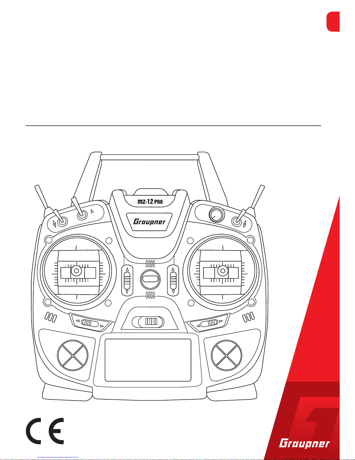
12 channel 2,4 GHz transmitter
mz-12PRO HoTT
Manual
Copyright © Graupner/SJ GmbH
Part 1
EN
Page 2

2 / 36
S1002.PRO_sh_V2
Page 3

3 / 36
S1002.PRO_sh_V2
Index
Introduction .............................................................................. 5
Service center ............................................................................ 5
Intended use ............................................................................. 6
Target group ....................................................................................6
Package content ........................................................................ 6
Technical data ............................................................................ 7
Symbol description .................................................................... 7
Safety notes ............................................................................... 8
For your safety by handling the transmitter ..................................9
For your safety by handling the battery .........................................9
Description of the transmitter ................................................. 11
Control elements on the transmitter ...........................................11
Connections and fixtures ..............................................................13
Attaching the transmitter neck-strap ........................................13
Jack socket .................................................................................13
Data socket .................................................................................13
Micro USB charging socket, see section "Battery charging" .....13
Transmitter preparation ........................................................... 14
Adjusting the length of the control sticks ....................................14
Opening the transmitter housing .................................................14
Neutralizing the control sticks ...................................................15
Brake spring and ratchet ............................................................16
Control sticks centering force ....................................................16
Closing the transmitter housing ...................................................16
Transmitter power supply .............................................................16
Installing the battery ..................................................................16
Charge the battery .....................................................................17
Removing the transmitter battery ............................................17
Low voltage warning ..................................................................17
Battery use timer in the display .................................................17
Starting up the transmitter ...................................................... 18
Use and menu functions ...............................................................19
Four-way keys .............................................................................19
Short-Cuts ..................................................................................20
Display and touchpad ................................................................22
Symbols in the info list of the display ........................................22
Display of the transmitter mode ...............................................22
Function field in the display .......................................................23
Hidden mode .............................................................................24
Stick calibration ..........................................................................24
Binding a receiver .........................................................................25
Page 4

4 / 36
S1002.PRO_sh_V2
Adjusting the control mode ..........................................................26
Display "USB connected" ..............................................................28
Charge the battery .....................................................................28
Joystick .......................................................................................28
PC COM Port ..............................................................................28
Servo display ........................................................................... 29
Firmware update ..................................................................... 32
Transmitter software update ........................................................32
Restoring the transmitter software ..............................................33
SIMPLIFIED DECLARATION OF CONFORMITY ............................ 34
Notes on environmental protection ......................................... 35
Care and maintenance ............................................................. 35
Warranty certification .............................................................. 35
Page 5
5 / 36
S1002.PRO_sh_V2
Introduction
Thank you very much for purchasing a Graupner mz-12 Pro HoTT
transmitter.
Read the manual carefully to use the transmitter optimally und first
of all to safely control your models. If you experience any trouble
during operation, take the instructions to help or ask your dealer or
Graupner Service Centre.
Due to technical changes, the information may be changed in this
manual without prior notice. Be always updated by checking periodically on our website,
www.graupner.de to be always uptodate with
the products and firmwares.
This product complies with national and European legal requirements.
To maintain this condition and to ensure safe operation, you must
read and follow this user manual and all the safety notes before
using the product!
Notes
• This manual is composed by two parts. Part 1 is contained in the
product's package content. Part 2 can be found in its last version
on www.graupner.de by the related item page.
• This manual is part of that product. It contains important information concerning operation and handling. Keep these instructions for future reference and give it to third person in case you
gave the product.
Service center
Graupner Central Service
Graupner/SJ GmbH
Henriettenstraße 96
D-73230 Kirchheim/Teck
Servicehotline
(+49) (0)7021/722-130
Monday - Thursday:
9:15 am - 4:00 pm
Friday:
9:15 am - 1:00 pm
service@graupner.de
Graupner USA
3941 Park Dr Suite 20-571
El Dorado Hills, CA 95762
Website: www.graupnerusa.com
Phone: +1 855-572-4746
Email:service@graupnerusa.com
Graupner in Internet For the service centers outside Germany please refer to our web site
www.graupner.de.
Page 6

6 / 36
S1002.PRO_sh_V2
Intended use
This transmitter system must only be used for the purpose specified
by the manufacturer for operation of remote control models without passengers. Any other type of use is impermissible and may
cause significant property damage and/or personal injury. No warranty or liability is therefore offered for any improper use not covered by these provisions.
In addition, it is explicitly pointed out that you must inform yourself
about the laws and regulations applicable at your respective starting
point before starting the remote control operation. Such conditions
may differ from state to state, but this must be followed in every
case.
Note
Read through this entire manual before you attempt to install or use
the transmitter.
Target group
The item is not a toy. It is not suitable for children under 14. The
operation of the transmitter must be performed by experienced
modelers. If you do not have sufficient knowledge about dealing
with radio-controlled models, please contact an experienced modeler or a model club.
Package content
• Transmitter mz-12 Pro HoTT
• 1s1p LiPo transmitter battery
• Transmitter strap
• Receiver (optional)
• Transmitter manual (Part 1)
• Receiver manual (optional)
The programming manual (manual part 2) can be found in its last
version on
www.graupner.de by the related item page.
Note
Graupner constantly works on the development of all products; we
reserve the right to change the item, its technology and equipment.
Page 7
7 / 36
S1002.PRO_sh_V2
Technical data
Transmitter mz-12 Pro HoTT
Frequency band 2,4 … 2,4835 GHz
Modulation FHSS
Transmitting power 100 mW EIRP
Control functions 12 functions of which 4 can be trimmed
Temperature range -10 … +55 °C
Antenna Integrated antenna
Operating voltage 3.4 … 5.5 V
Power consumption Approximately 180 mA
Dimensions Approx. 190 x 185 x 90 mm
Weight approx. 700
g with battery
Note
The technical data of the optional receiver are available in the manual included in the receiver package content.
Symbol description
!
Always observe the information indicated by this warning sign. Particularly those which are additionally marked with the words CAU-
TION or WARNING. The signal word WARNING indicates the poten-
tial for serious injury, the signal word CAUTION indicates possibility
of lighter injuries.
The signal word Note indicates potential malfunctions.
Attention indicates potential damages to objects.
Page 8

8 / 36
S1002.PRO_sh_V2
Safety notes
!
These safety instructions are intended not only to protect the product, but also for your own and other people’s safety. Therefore
please read this section very carefully before using the product!
• Do not leave the packaging material lying around, this could be
a dangerous toy for children.
• Persons, including children, with reduced physical, sensory or
mental capabilities, or lack of experience or knowledge, or not
capable to use safely the transmitter must not use the transmitter without supervision or instruction by a responsible person.
• Operation and use of radio-controlled models needs to be
learnt! If you have never operated a model of this type before,
start carefully and make yourself familiar with the model's
reactions to the remote control commands. Proceed always
responsibly.
• Protect all equipment from dust, dirt, moisture. All equipment
must be protected from vibration as well as excessive heat or
cold. The models may only be operated remotely in normal
outside temperatures such as from -10°C to +55°C.
• First, always perform a range and function test on the ground
before you start using your model. Only so you can grant a safe
use! How to perform a range test is explained in the Part 2 of
the manual.
• Always use all your HoTT components only with the latest
firmware version.
• If you have questions which cannot be answered by the operating manual, please contact us or another expert in the field.
Page 9
9 / 36
S1002.PRO_sh_V2
For your safety by handling the transmitter
!
WARNING
Also while programming the transmitter, make sure that a motor
connected in the model cannot accidentally start. Disconnect the
fuel supply or drive battery beforehand.
!
CAUTION
Avoid every kind of short-circuit in all sockets of the transmitter
and of the receiver! Risk of fire! Use only the suitable connectors.
In no case the electronic component of the transmitter or of the
receiver may be changed or modified. Any interference will void
the authorization.
Note
During transport protect the model and the transmitter from damages.
For your safety by handling the battery
!
CAUTION
• Protect all equipment from dust, dirt, moisture. Only use in dry
locations.
• Do not use any damaged battery.
• Any alterations to the battery can cause serious injury or burns.
• Batteries may not be heated, burned, short-circuited or charged
with excessive current or with reversed polarity.
• Combustible or highly flammable objects are to be kept away
from the charging area.
• Never leave the charger unattended when it is connected to
the power supply.
• Please charge your batteries only in rooms fitted with a smoke
detector.
• Always charge the battery with a suitable charger.
• The maximum quick charging current specified for the respective cell type may not be exceeded.
• If the battery heats up above 60°C while it is being charged,
stop charging and let the battery cool down to approximately
30 - 40°C.
Page 10

10 / 36
S1002.PRO_sh_V2
• Never charge batteries that have already been charged or hot
ones. If a cell in a battery pack has become particularly hot following a quick-charge process, this may indicate a defect in
that cell. Do not use the battery pack any more!
• The batteries may not be modified. Do not directly solder or
weld the cells.
• If handled improperly, there is a danger of fire, explosion, irritation and burns. To extinguish a fire use: water, CO
2
or sand.
• Leaked electrolyte is caustic! It should not be touched or come
into contact with your eyes. In case of emergency, rinse with a
large quantity of water and consult a Med. Doctor.
Special instructions
• To charge and discharge batteries, only use specifically designed
chargers/dischargers with balancer connector.
• The white connector (cell count + 1 pole) is designed for the connection to a LiPo balancer or a battery charger as a single cell
charger with a manual cell balancer.
Safety notes for stocking batteries
• Batteries may only be stored in dry rooms with an ambient temperature of +5°C to +25°C.
• If the LiPo battery must be stored for a longer period, the voltage
per cell should be about 3,8V. If the cell voltage drops below 3 V,
they must be recharged immediately. Deep discharge makes the
battery short-term, longer storage in discharged as well as fully
charged state make the battery in the long term useless.
Page 11
11 / 36
S1002.PRO_sh_V2
Description of the transmitter
8
6
1
2
3
4
5
7
9
108
11
12
13
14
15
16 17
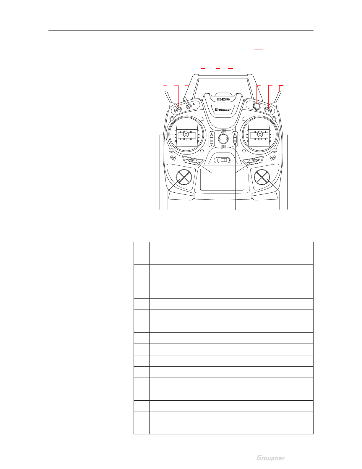
Control elements on the transmitter
1 antenna integrated in the case
2 Eyelet for neck strap
3 Proportional dial DV
4 2 way switch SW 3
5 3 way switch SW 6 and 7, push-switch, latching-switch
6 Right stick
7 Right four way keys
8 Trim
9 ON/OFF switch
10 LCD
11 Left four way keys
12 Left stick
13 3 way switch SW 4 and 5
14 2 way switch SW 1
15 2 way switch SW 2
16 Carrying handle
17 Central status LED
Page 12

12 / 36
S1002.PRO_sh_V2
mz-12PRO
1
1
1
1
1
1
11 3 4
5
1
2
1 Case screws
2 Battery case cover
3 3,5 mm jack to connect earphones or a DSC cable
4 Data socket to connect a smart box
5 Micro USB port, to use as:
Charge port, update port, joystick function
Page 13

13 / 36
S1002.PRO_sh_V2
Connections and fixtures
Attaching the transmitter neck-strap
On the upper side of the transmitter there is an eyelet which can be
used to hook a neck-strap.
Jack socket
The port for a 3,5 mm jack is located on the back of the transmitter.
Depending on the settings in the menu (OHRH or DSC) this interface
can be used as a earphone port or as a DSC cable port.
Headphone connection
Though this interface both acoustic signals and voice messages are
emitted.
The volume can be controlled by "Voice volume" and "Signal volume" in the general settings.
DSC connection
Through a DSC cable the port can serve to use the transmitter with
a simulator o to connect it with another one in Teacher/pupil mode.
Attention
When your transmitter is directly connected to a desktop computer
by a connecting cable (DSC cable) and/or a computer interface is
connected to your simulator, the transmitter may be destroyed
by electrostatic discharge. This type of connection should therefore
only be used if you protect yourself from electrostatic discharge
while operating the simulator by wearing a commercially available
grounding armband. Graupner therefore strongly recommends
only using wireless simulators.
Switch on the line "DSC output" of the menu "general Set." to DSC
mode if necessary. In this way you can change the base display too.
Right in the display appears "DSC".
To ensure a correct DSC connection, observe the following
1. Perform any necessary adaptations in the menu.
2. Connect one end of the DSC cable in the DSC port of the switchedoff transmitter and the other end to the device to be connected.
3. Switch the transmitter on.
Data socket
The data socket is suitable for connection of a smart box or an external Bluetooth module.
Micro USB charging socket, see section "Battery charging"
Voice volume
Back port
Region setting
3
OHRH
Europe
Signal volume
3
Display light
always
Page 14
14 / 36
S1002.PRO_sh_V2
Transmitter preparation
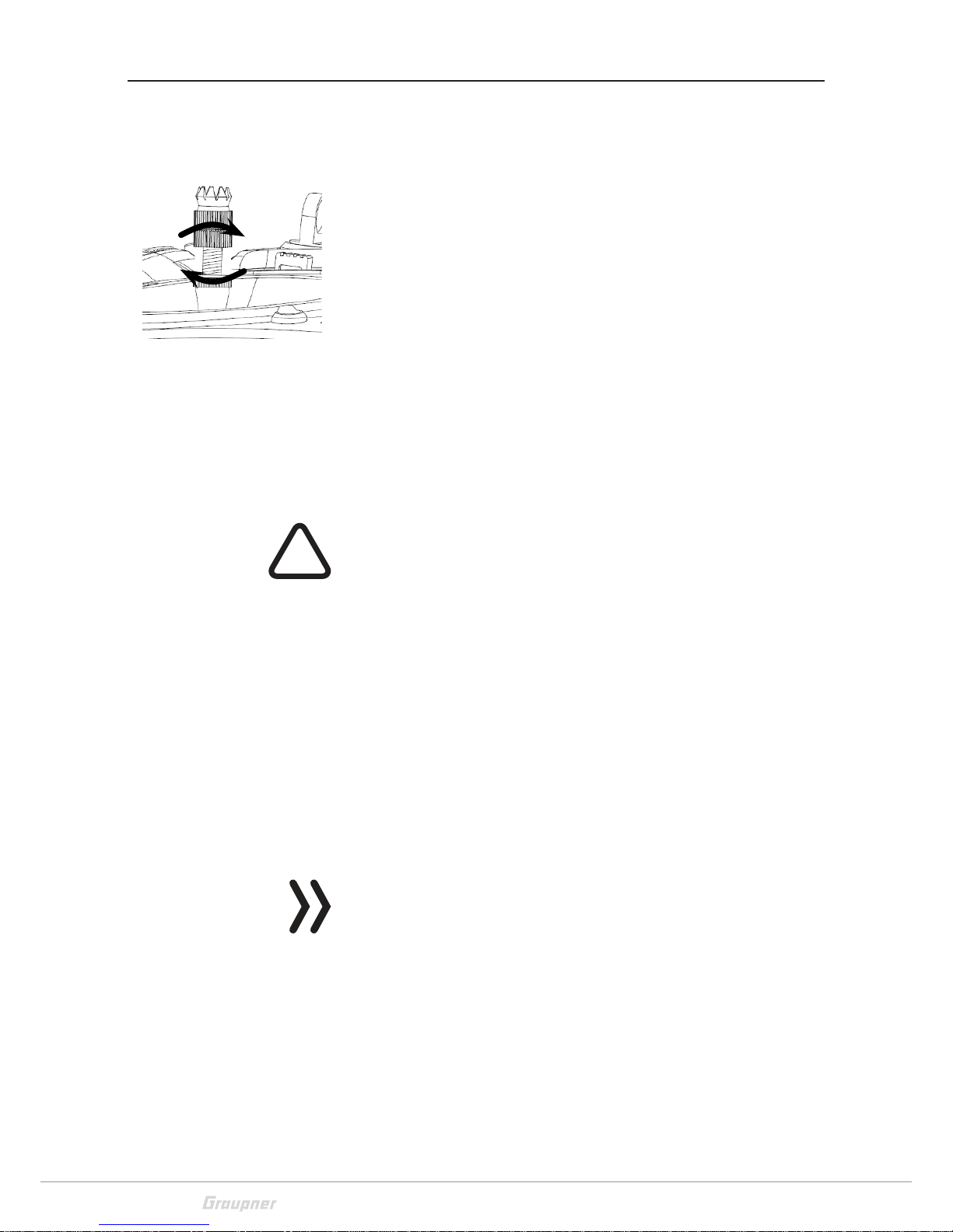
Adjusting the length of the control sticks
Length of both control stick can be adjusted. Hold down the bottom
half of the knurled grip, and loosen the screwed connection by turning the top part.
You can now lengthen or shorten the control stick by screwing it up
or down. Then clamp the top and bottom part of the grip by rotating them against each other.
Opening the transmitter housing
The transmitter should be opened only in the following cases:
• If a self centering stick has to be converted in non self centering
• If a non self centering stick has to be converted in self centering
• To set the control stick centering force
!
CAUTION
Never switch the transmitter on while the housing is open. Risk of
short-circuit! Before opening the housing remove the batteries.
Open step by step
1. Before opening the housing switch the transmitter off.
2. Open the battery case.
3. Remove the transmitter battery lifting it from one side and gently
release it from the Velcro tape.
4. Retire the connection plug.
5. Unscrew the eight screws with a cross-screwdriver.
6. Hold both housing halves with both hands and let the screws fall
on a proper surface turning the transmitter upside-down.
7. Rotate the lower half carefully and fold it to the bottom.
Note
Cables connect the lower half of the housing with the upper part
electronic components. This connection must not be damaged! Do
not touch the electronic boards.
Page 15

15 / 36
S1002.PRO_sh_V2
2
2
1
3
3
3
3
4
4
1 Transmitter antenna integrated in the handle
2 Adjust screws for brake spring (outer)
and ratchet (inner)
3 Stick self centering force adjust screws
4 Screw to convert from neutralizing to non neutralizing and
vice versa
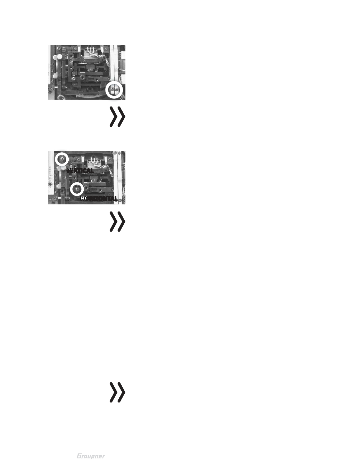
Neutralizing the control sticks
Both control sticks can be set from neutralizing to non-neutralizing
and vice versa. Locate in the right-hand control stick gimbal the
screw surrounded by a white circle in the picture.
Turn the screw toward the inside of the transmitter until the relevant
control stick can move freely from stop to stop, or turn it outward
until the control stick resets itself independently.
Note
The left-hand control stick gimbal is specular to the left one, so that
here the screw is located right under the middle.
Page 16
16 / 36
S1002.PRO_sh_V2
Brake spring and ratchet
The outboard screw of the two marked in the figure adjust the braking force.
The inboard screw adjusts the strength of the ratchet for the respective control stick.
Note
The left-hand control stick gimbal is specular to the left one, so that
here the screws are located left on the top side.
Control sticks centering force
The control sticks' restoring force can also be adjusted. The adjustment is located next to the return springs.
By turning the respective adjust screw the spring force can be
adjusted:
Right turn = return harder
Left turn = return softer
Note
The left-hand control stick gimbal is specular to the left one, so that
here the screws are located left in the middle.
Closing the transmitter housing
Closing step by step
1. Check if the upper and the lower part of the transmitter housing
are correctly coupled and the tiny cables are properly placed.
2. Screw the housing screws in their original position.
3. Connect the battery.
4. Close the battery case.
Transmitter power supply
The mz-12 Pro HoTT transmitter is normally delivered with a 1s2p
LiPo battery.
Installing the battery
Note
Pay attention when inserting the battery to the correct position and
make sure the contacts are solid. Interruptions of the power supply
to the transmitter during the use of the models can lead to big danger for your self and for other people!
VERTICAL
HORIZONTAL
VERTICALVERTICAL
HORIZONTALHORIZONTAL
Page 17

17 / 36
S1002.PRO_sh_V2
Connect the battery plug in the transmitter socket with the correct
polarity. Next to the socket the same symbols are printed: Red = +
Black/Brown = -
Place the battery into its compartment and close the cover.
Charge the battery
The transmitter battery is charged by means of the micro USB socket
on the back of the transmitter with the charging currents (5 V / max.
0.5 A) which are common to USB2 ports. To do this, the included USB
cable must be connected to a USB compatible charger.
The charging process is shown through the red lightning Graupner
text. The indication quits when, with switched off transmitter, the
battery is full.
If the transmitter is switched on the charge time is longer than if the
transmitter is switched off.
!
WARNING
The charger should always be supervised during charge and it
should be used only in rooms fitted with a smoke detector.
Removing the transmitter battery
Remove the battery case cover. Detach the battery by lifting it from
the side of the Velcro and then gently pull the plug of the lead wire.
Possibly charge the battery outside the transmitter according to the
instructions of the charger.
Low voltage warning
The transmitter battery voltage should be monitored in the LCD display during operation. In case the voltage drops under a preset
threshold, standard setting 3,6 V, an acoustic warning signal is emitted and in the display appears in a warning note "battery needs
charging".
Now at the latest, stop operation and recharge the transmitter battery!
Battery use timer in the display
The battery use timer is shown in the lower left part of the display.
The battery use time is added at every use. After every charge or battery exchange the timer is reset to "00:00". This happens only if the
battery voltage increases at least of 0,3V.
M-0 1
1:23h
Stop
Log
0:00
0:00
5.5V
3.5V
NR
0:0V
Alpha 110
BIND?
OK
Battery
must be
charged !!
Page 18

18 / 36
S1002.PRO_sh_V2
Starting up the transmitter
At the factory, the first six model memories are preloaded with a
Copter model from the Graupner product range so that each of
these 6 models can be put into operation immediately after the
binding of a receiver.
It is important to know this before the transmitter is put into operation, since the throttle / pitch position is first checked on the side of
the software after switching on the transmitter. If these are outside
the idle range, and there is a risk of spinning rotors, an audible warning will sound and the warning message shown on the left will be
displayed. In order to stop them both, the left stick is to be brought
to the pilot-side stop.
As soon as the left stick is at the backstop, the warning "Throttle too
high!" is blanked out or not even displayed if it is already "at the rear"
when the transmitter is switched on. In both cases, the question
"BIND OK?“ is visible.
You can decide to wait until the question "BIND OK?" disappears
automatically or you can shorten the waiting time manually, by pushing the ENT button of the right four-way button:
• In the one case, the "Fail Safe" setting, which is only fragmentarily visible under the question "BIND OK?", is completely visible. This note, which is completely uninteresting in this situation,
is also automatically dimmed after a few seconds. Alternatively,
press the ENT key of the right four-way key to switch directly to
the menu selection, as shown on the left. Further information
can be found further back and in the manual part 2, which can
be found at
www.graupner.de on the product page.
• If you do not wait for "BIND OK?" to be hidden, you can press the
ENT key to change the focus directly to the "BIND"menu of the"
Transmitter Setting "menu. Here, a receiver which is already
ready for operation can be connected to the transmitter without
further detours. Further information can be found further back
and in the manual part 2, which can be found at www.graupner.de
on the product page.
M-01
0:01h
Stop
Log
0:00
0:00
5.5V
3.9V
NR
0:0V
Alpha 110
Throttle
too
high!
M-01
0:01h
Stop
Log
0:00
0:00
5.5V
3.9V
NR
0:0V
Alpha 110
Fail Safe
ein-
stellen
BIND?
OK
Model
memory
D/R
ExpoTxsetting
Ctl
setting
Servo
setting
Wing
mix
M. Type
phase
Th r.
curve
Control mode
2
Receiver output
Rx bind
–––
Range test
99sec
RF module
OFF
Page 19
19 / 36
S1002.PRO_sh_V2
Use and menu functions
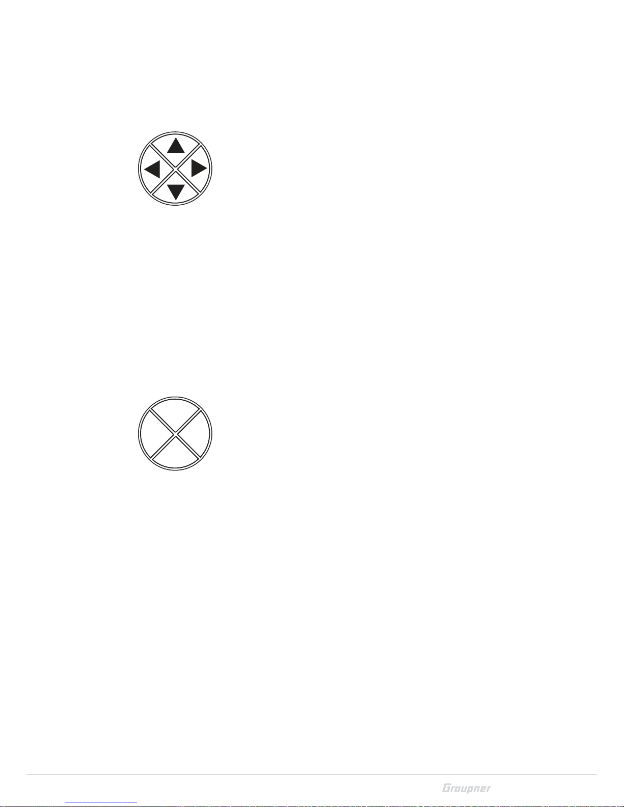
Four-way keys
Buttons to the left of the display
Hereinafter referred to as left, right upper and lower selection keys.
These keys are used to scroll through lists, columns, etc., in the same
way as their arrow directions, and values are changed.
Furthermore,
• Pressing one of these selection buttons from the base display will
bring up the "display telemetry data".
• Simultaneously press the left and the right selection keys to
reset in almost every value field a changed parameter back to the
default value. (CLEAR function).
• Simultaneously press the left and the right selection keys to recall
the sensors selection within the menu "Settings & data view" of
the "Telemetry" menu To change within the sensors push the
upper and the lower key.
• Simultaneously press the left and the right selection keys to recall
the "Hidden mode" from the base display of the transmitter as
from almost every menu position.
Buttons to the right of the display
• ENT button
- The ENT key is used mainly to confirm a selection made
through the selection keys. For example a menu selected
through the selection key can be opened by pushing the ENT
ke y.
- Push the ENT key to recall the selection menu from the base
display.
- Push the ENT key to activate and deactivate or confirm
changed values in activated (represented with inverted contrast) value fields within the setting menu.
• ESC button
Pressing the ESC button brings about a stepwise back to the basic
display.
Any setting changed in the meantime is retained.
• VIEW button
Pushing the four-way keys will cause a jump from the transmitter's base screen or from almost any menu position to the "Servo
display" menu.
• TLM button
Pushing the TLM key will cause a jump from the transmitter's
base screen or from almost any menu position to the "Telemetry" menu.
ENT
VIEW
ESC
TLM
Page 20

20 / 36
S1002.PRO_sh_V2
Note
In the event the four way keys do not exhibit any functionality
immediately after switching the transmitter off and then on again
right away, this is not a fault. Just switch the transmitter off again
then wait for several seconds before switching it on again.
Short-Cuts
• CLEAR
Simultaneous touch of the left and the right selection keys of the
left four way keys will restore the active entry field's changed
parameter value back to its default value.
• "Servo display"
Pushing the four-way keys will cause a jump from the transmitter's base screen or from almost any menu position to the "Servo
display" menu.
• "Telemetry" menu
Pushing the TLM key will cause a jump from the transmitter's
base screen or from almost any menu position to the "Telemetry" menu.
- Within the "Setting & data view" sub-menu of the "Teleme-
try" menu, it is possible to recall the sensor selection by pushing simultaneously the left and the right selection keys.
- The desired sensor can be selected in a rotation order through
the upper and lower selection keys.
Push the ESC key to come back to the exit position.
• Telemetry data display
You can move from the base display of the transmitter to the
"Telemetry data display" pushing one of the selection keys.
- Within the "Telemetry data display" you can recall the list of
the selectable sensors through the upper and lower selection
keys.
- Push the ESC or ENT key to move back to the base display.
Note
A complete description of the "Telemetry menu" and "Telemetry
data display" can be found in the Part 2 of the manual available for
download on www.graupner.de/Productpage.
Page 21

21 / 36
S1002.PRO_sh_V2
• "HIDDEN MODE"
Simultaneously press the left, the right and the lower selection
keys of the four-ways key to open the "Hidden mode" menu from
the base display of the transmitter as from almost every menu
position.
• Key lock
The four-way keys can be locked by pushing simultaneously the
TLM and VIEW keys for about 1 second in the base display.
- The key lock function is displayed by a lock symbol: The con-
trols remain operational.
- Push again the TLM and VIEW keys for about 1 second to
remove the key lock.
Page 22

22 / 36
S1002.PRO_sh_V2
Display and touchpad
M-01
1:23h
Stop
Flight
0:00
0:00
5.5V
3.9V
NR
5:1V
GRAUBELE
DSC
1
2
3
4
5
6
7
8
4
4
11
9
10
1 Model name
2 Memory 1 ... 250
3 Model type display
Plane, helicopter, copter, truck, boat models
4 Optical display of the trim position
5 Flight chronometer in min:s (forward/reverse)
6 Flight or drive chronometer in min:s (forward/reverse)
7 Transmitter battery voltage
(when a determined threshold is trespassed a warn message is displayed, contemporary a warn signal is emitted).
8 Transmitter use timer since last charge in h:min
9 Display of the transmitter mode
10 Status display
10 Phase name
Symbols in the info list of the display
No receiver in range
Display of the signal strength of the signal coming back from receiver
Button lock inactive / active
The right info-field is empty in case of not bound model memory
The active model memory is bound to a receiver
No connection to receiver
Current operating voltage of the receiver power supply with symbol
display of the power supply charge state
Display of the transmitter mode
NR: normal mode
TP: Teacher/pupil mode
0.0 V
5.2 V
Page 23

23 / 36
S1002.PRO_sh_V2
Function field in the display
Depending on the given menu, certain function fields will appear on
the bottom display line.
A marked function is activated by pushing the ENT key.
SET (SET)
SEL (SELECT)
STO (STORE)
SYM Set values symmetrically
ASY Set values asymmetrically
Switch symbol field
(assignment of all types of switches)
After the selection of the so marked column
change to the following page
Come back with ESC
SET SEL STO SYM ASY
Page 24

24 / 36
S1002.PRO_sh_V2
Hidden mode
Simultaneously press the left, the right and the lower selection keys
of the four-ways key to open the "Hidden mode" menu from almost
every menu position.
Stick calibration
If the middle position of the self neutralizing control stick is not
exactly 0 % of the control course, this can probably be corrected in
this menu.
Verifying the stick calibration step by step
1. Change to the "Model memory" menu.
2. Initialize a free model memory with a suitable model memory.
3. Nothing should be changed in the settings and trim positions.
4. Change to the "Servo display" menu push the VIEW key of the
four-way key.
5. If all of the self neutralizing control sticks is in its middle position,
the display of the control channels 2 ... 4 should look like the representation on the left.
The not self neutralizing control stick of the channel 1 is placed,
according to this display, on its end point on the idle position side.
If the display looks as shown, everything is ok and the previously created model memory can be deleted again.
If the display deviates from the desired values, these can be calibrated in the "Stick calibration" sub-menu of the "HIDDEN MODE"
menu.
Stick calibration step by step
1. Leave the model memory created as described in "Checking the
stick Calibration Step-by-Step" activated.
2. Push simultaneously the left, the right and the lower selection
keys.
3. Push the ENT button of the right four-way button.
The two flashing arrows indicate the actual position of the control stick to be calibrated.
4. Possibly use the selection buttons on the left four-way button to
select the position of the control stick to be calibrated.
ശ Gently push the control stick to the end points.
5. Push the ENT key.
6. Use the same procedure for the control stick positions.
7. Push the ESC key to stop the procedure.
HIDDEN MODE
STICK CALIBRATION
STICK CALIBRATION
0%
1
3
5
7
+
0%
0%
9
11
0%
0%
2
4
6
8
+
0%
0%
0%
0%
10
12
0%
–100%
0%
0%
Page 25

25 / 36
S1002.PRO_sh_V2
Binding a receiver
To establish a connection with the transmitter, Graupner HoTT
receivers must first be "bound" to at least one model memory in "its"
Graupner HoTT transmitter. This process is generally called "binding" and it can be repeated all the times it is needed.
This binding of a receiver is normally performed always model memory specifically, but it can be changed in every moment to transmitter specific, for every not-bound model memory of the same transmitter in the menu line "Binding type".
The complete sequence of the binding process results from the combination of the description of the transmitter-side part of the binding process in part 2 of the transmitter instructions as well as from
the description of the receiver-specific procedure to be found in the
respective receiver manual.
Basic procedure step by step
1. Move transmitter and receiver at a moderate distance from each
other.
2. Switch the mz-12 Pro HoTT transmitter on without RF module or
set the RF module on "OFF" in the "RF module" line of the "Tx setting" menu.
3. Select the "Tx setting" menu in the transmitter.
4. Push the ENT key.
5. Use the selection keys to move to the "Bound receiver" line.
6. Switch the receiver system power supply on.
... Receiver with SET button
7. Push the SET button on the receiver for approx. 3 seconds.
... Receiver without SET button
7. The receiver is automatically in binding mode for a few seconds
after switch on.
8. Push the ENT key on the transmitter to start the binding process
on the transmitter side.
If the LED on the receiver indicates the correct connection according
to its description and in the value field of the line "Bound receiver"
appears the abbreviation of the receiver name, the binding process
has been completed successfully. Otherwise change the positions of
the devices and repeat the entire procedure.
Model
memory
Wing
mix
M. Type
phase
Servo
setting
Ctl
setting
D/R
Expo
Tx
setting
Thr.
curve
Control mode
2
Receiver output
Rx bind
–––
Range test
99sec
RF module
OFF
Control mode
2
Receiver output
Rx bind
–––
Range test
99sec
RF module
OFF
Page 26

26 / 36
S1002.PRO_sh_V2
Adjusting the control mode
The transmitter is sent out of the factory with the control mode 2
software. That is the reason why also every new model memory will
be initialized with the control mode 2.
However, this default value can always be adapted to the user's own
habits in the "Control mode" line of the "Tx settings" menu.
Change control model step-by-step
1. Move to the "Tx settings" menu.
The value field of the "Control mode" line is already framed.
2. Push the ENT key.
3. Set the desired control mode through the selection keys:
4. Push the ENT key.
5. Leave the menu pushing the ESC key.
‖ The following control modes are available:
-
(Fixed-wing models)
MODE 2 (Throttle left)
Elevator
Elevator
Rudder
Rudder
Full throttle
Motor idle
Querruder
Querruder
Full throttle
Motor idle
Rudder
Rudder
Elevator
Elevator
Aileron
Aileron
Elevator
Elevator
Aileron
Aileron
Full throttle
Motor idle
Rudder
Rudder
Full throttle
Motor idle
Aileron
Aileron
Elevator
Elevator
Rudder
Rudder
MODE 1 (Throttle right)
MODE 3 (Throttle right)
MODE 4 (Throttle left)
- (Helicopter models)
MODE 2 (Throttle left)
Nick
Nick
Tail rotor
Tail rotor
Motor / Pitch
Motor / Pitch
Roll
Roll
Motor / Pitch
Motor / Pitch
Tail rotor
Tail rotor
Nick
Nick
Roll
Roll
Nick
Nick
Roll
Roll
Motor / Pitch
Motor / Pitch
Tail rotor
Tail rotor
Motor / Pitch
Motor / Pitch
Roll
Roll
Nick
Nick
Tail rotor
Tail rotor
MODE 1 (Throttle right)
MODE 3 (Throttle right)
MODE 4 (Throttle left)
Control mode
2
Receiver output
Rx bind
–––
Range test
99sec
RF module
OFF
Page 27

27 / 36
S1002.PRO_sh_V2
-
(Copter)
MODE 2 (Throttle/Pitch left)
Nick
Nick
Yaw
Yaw
Throttle/Pitch
Throttle/Pitch
Roll
Roll
Throttle/Pitch
Throttle/Pitch
Yaw
Yaw
Nick
Nick
Roll
Roll
Nick
Nick
Roll
Roll
Throttle/Pitch
Throttle/Pitch
Yaw
Yaw
Throttle/Pitch
Throttle/Pitch
Roll
Roll
Nick
Nick
Yaw
Yaw
MODE 1 (Throttle/Pitch right)
MODE 3 (Throttle/Pitch right)
MODE 4 (Throttle/Pitch left)
- (Truck and boat models)
MODE 2 (for/backward left)
left
right
forward/backward
forward/backward
forward/backward
forward/backward
left
right
forward/backward
forward/backward
left
right
forward/backward
forward/backward
left
right
MODE 1 (for/backward right)
MODE 3 (for/backward right)
MODE 4 (for/backward left)
.
Page 28

28 / 36
S1002.PRO_sh_V2
Display "USB connected"
Charge the battery
As long as a USB cable is connected to the switched-off transmitter
and this is connected to a suitable USB power source, the transmitter is automatically charged until the battery is full.
If the transmitter is switched on during a charging process, a selection menu appears in the display. In this "Charge battery" is activated
by default and a time display up on the right counts backwards from
10:
• You can wait until this window disappears or the operation is
abbreviated by pressing the ENT key.
• Within the remaining time, one of the other two lines can be
selected with the selection keys, and then the ENT key can be
pressed.
Joystick
The "Joystick" line must be selected if the transmitter is to be recognized as a "joystick" by a PC connected via USB cable, for example,
to operate a flight simulator.
In the "USBjoystick" line of the "General settings" menu the control
course can be adjusted within 0 … 100 % or from -100 % to +100 %.
The standard setting suitable for the most flight simulators is 0 …
100 %.
PC COM Port
Select the "PC COM Port" line if the transmitter is connected to a PC
for update reasons.
M-01
0:01h
Stop
Log
0:00
0:00
5.5V
3.9V
NR
0:0V
Alpha 110
Gas
zu
hoch!
USB connected 7
PC COM Port
Joystick
Battery charge
USBjoystick
Back port
DATA sel.
DSC output
0~ 100
OHRH
PPM10
Telemetry
Signal volume
3
Page 29
29 / 36
S1002.PRO_sh_V2
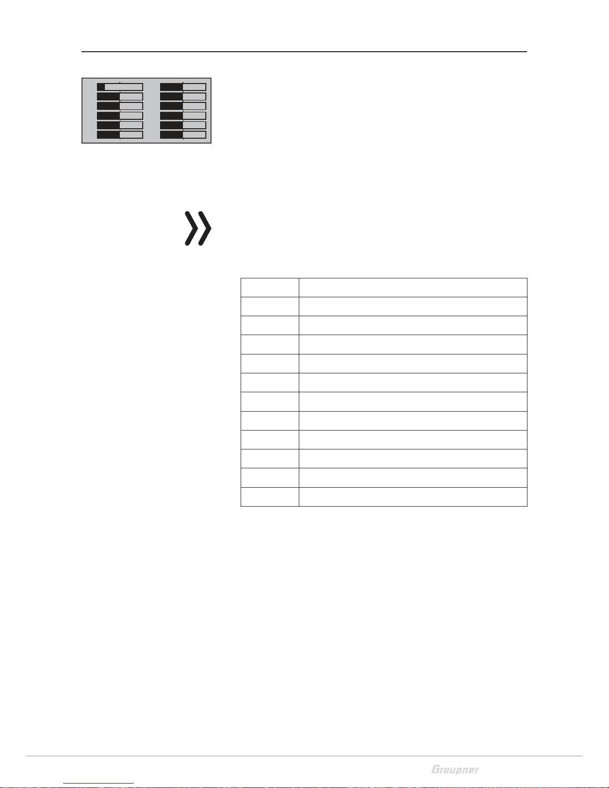
Servo display
The graphical representation of the current servo position can be
recalled at any time by pushing the VIEW key of the right four-way
keys from the base display so as from almost every other menu positions.
The current setting of each servo is displayed precisely between
-150% and +150% of the normal path taking into account the control
and servo settings, dual rate/expo functions, the interaction between
the linear and curve mixes, etc.
0% equals the middle position of the servo.
Attention
All the program steps on the model have to be tested before first
use to make sure there are no errors!
• For fixed wing models, the display follows the assignment below:
Bar 1 Throttle/brake servo or speed controller
Bar 2 Aileron or left aileron
Bar 3 Elevator or elevator/rudder in a V-tail
Bar 4 Rudder or rudder/elevator in a V-tail
Bar 5 Aileron right / free channel
Bar 6 Free or flap or flap left
Bar 7 Free or flap right
Bar 8 Free or 2nd elevator servo
Bar 9 Free or special function
Bar 10 Free or special function
Bar 11 Free or special function
Bar 12 Free or special function
1
3
5
7
+
0%
0%
9
11
0%
0%
2
4
6
8
+
0%
0%
0%
0%
10
12
0%
–100%
0%
0%
Page 30

30 / 36
S1002.PRO_sh_V2
• For helicopter models, the display follows the assignment below:
Bar 1 Pitch or roll (2) or nick (2) servo
Bar 2 Roll (1) servo
Bar 3 Nick (1) servo
Bar 4 Tail servo (gyro)
Bar 5 Nick (2) servo
Bar 6 Throttle servo or governor
Bar 7 Gyro
Bar 8 Speed controller
Bar 9 Free or special function
Bar 10 Free or special function
Bar 11 Free or special function
Bar 12 Free or special function
• The display follows the assignment below for copter models:
Bar 1 Pitch
Bar 2 Roll
Bar 3 Nick
Bar 4 Yaw
Bar 5 Free or special function
Bar 6 Free or special function
Bar 7 Free or special function
Bar 8 Free or special function
Bar 9 Free or special function
Bar 10 Free or special function
Bar 11 Free or special function
Bar 12 Free or special function
Page 31

31 / 36
S1002.PRO_sh_V2
• The display follows the assignment below for trucks:
Bar 1 Throttle/brake or forward/backward function
Bar 2 Left/right function
Bar 3 Free or special function
Bar 4 Free or special function
Bar 5 Free or special function
Bar 6 Free or special function
Bar 7 Free or special function
Bar 8 Free or special function
Bar 9 Free or special function
Bar 10 Free or special function
Bar 11 Free or special function
Bar 12 Free or special function
Pushing the ESC key of the right four-way keys you turn back to the
related output point.
Notes
• The servo display refers exclusively to the original sequence of
the servos. It does not refer to any changes to the outputs made
in the "Transmitter settings" menu, or via telemetry in
the "Receiver output " sub-menu of the "Transmitter setting"
menu.
• The count of the channels displayed in this menu refers to the
12 control channels available in this transmitter mz-12 Pro HoTT.
The number of usable channels depends on the type of receiver
as well as the number of connected servos and may therefore
be significantly less.
Page 32
32 / 36
S1002.PRO_sh_V2
Firmware update
Firmware updates of the transmitter are carried out via the back
micro USB port and the setting "PC COM Port" in the transmitter
using a laptop or PC with Windows 7 ... 10.
The required programs and files are enclosed in a software pack and
can be found for the corresponding product at
www.graupner.de.
Download this software package from the Internet, and unpack it on
your Windows PC or laptop.
The update is carried out via the "Firmware Upgrade" program section of the program "Firmware_Upgrade_gr_Studio". Please follow
the notes of the software. The further procedure is also described in
detail in the manual contained in the data package. You can also singularly download these from the download page of the product at
www.graupner.de.
Notes
• Please note that compatible firmware is required for reliable
communication between the HoTT components. The programs
and files that are required for updates are therefore combined
into a single pack that is currently named "HoTT_Software_
V4.zip".
• Only operate your transmitter using the current software version. The current firmware version can be found on the Internet
at
www.graupner.de.
Transmitter software update
Perform update step by step
1. Before each update check the transmitter battery charge status.
2. Connect the back micro USB port of the switched off transmitter
through the included USB cable to a PC.
ശ Do not disconnect the link to the computer during an update!
Make sure that the link between the transmitter and computer is operational.
3. Switch the transmitter on, select in "PC COM Port" in the display
and push the ENT key.
4. Select the correct COM port in the program part "Port select" of
the "Firmware_Upgrade_gr_Studio".
5. Launch the Firmware_Upgrade_gr_Studio" and store for safety
reasons all the occupied model memories through the program
part "Model Data" to be able to restore them.
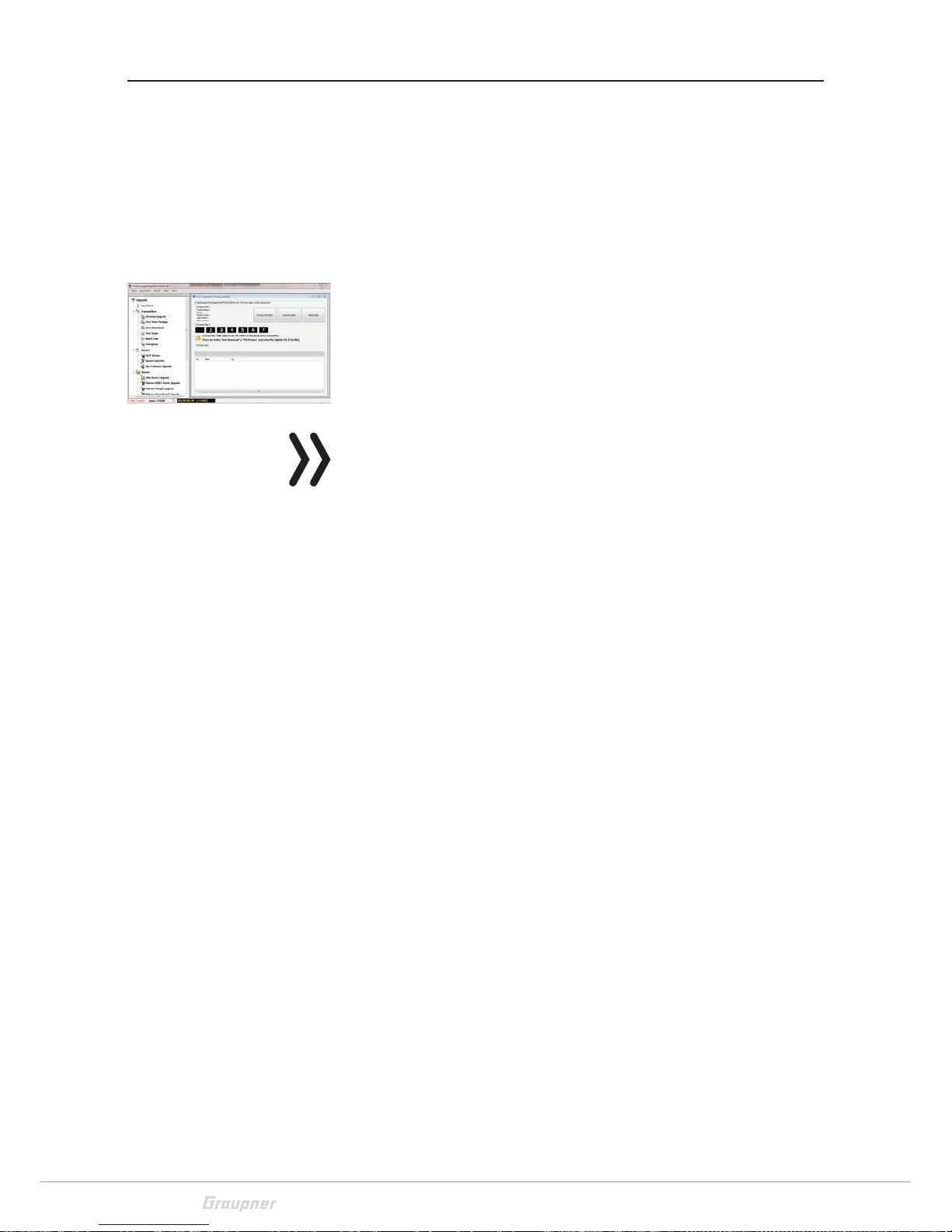
6. Launch the "Firmware Upgrade" program section of the program
"Firmware_Upgrade_gr_Studio".
Page 33

33 / 36
S1002.PRO_sh_V2
7. Select "Load automatically" or "Open file".
8. Select the "mz-12Pro_...bin" file.
The data transfer to the transmitter begins.
9. The end of the data transfer will be indicated by the update program. The transmitter indicates the end of the transfer though
the power on melody.
10. Switch off the transmitter and interrupt the USB connection to
the PC.
11. After each update, check if the model functions are correct.
Restoring the transmitter software
If a firmware update for the transmitter is unsuccessful or the transmitter program freezes and the transmitter cannot be turned off
using the "POWER" switch, then remove the transmitter's battery
after setting the switch to "POWER = OFF" position, or pull the plug
from the transmitter battery. While making sure that the POWER
switch is in the "OFF" position, wait a few seconds and then reconnect the disconnected battery.
In this case as well, download a current software package, as
described at the beginning of this section, from the Internet and
unzip it in your computer or, if you have already done this, start the
"Firmware_Update_gr_Studio" and follow the information in the
section "Restoration" in the instructions provided in the software
package.
Page 34

34 / 36
S1002.PRO_sh_V2
SIMPLIFIED DECLARATION OF CONFORMITY
Graupner/SJ hereby declares that the S1002.Pro mz-12 Pro HoTT
complies with the Directive 2014/53/EU.
The full text of the EU Declaration of Conformity is available at the
following Internet address: www.graupner.de
Page 35

35 / 36
S1002.PRO_sh_V2
Notes on environmental protection
If this symbol is on the product, instructions for use or packaging, it
indicates that the product may not be disposed with normal household waste once it has reached the end of its service life. It must be
turned over to a recycling collection point for electric and electronic
apparatus.
Individual markings indicate which materials can be recycled. You
make an important contribution to protection of the environment by
utilizing facilities for reuse, material recycling or other means of
exploiting obsolete equipment.
Batteries must be removed from the unit and disposed of separately
at an appropriate collection point. Please inquire if necessary from
the local authority for the appropriate disposal site.
Care and maintenance
The product does not need any maintenance. Always protect it
against dust, dirt and moisture.
Clean the product only with a dry cloth (do not use detergent!) lightly
rub.
Warranty certification
Graupner/SJ GmbH, Henriettenstrassee 96, 73230 Kirchheim/Teck
grants from the date of purchase of this product for a period of 24
months. The warranty applies only to the material or operational
defects already existing when you purchased the item. Damage due
to misuse, wear, overloading, incorrect accessories or improper handling are excluded from the guarantee. The legal rights and claims
are not affected by this guarantee. Please check exactly defects
before a claim or send the product, because we have to ask you to
pay shipping costs if the item is free from defects.
These operating instruction are exclusively for information purposes
and are subject to change without prior notification. The current
version can be found on the Internet at
www.graupner.de on the
relevant product page. In addition, the company Graupner/SJ has no
responsibility or liability for any errors or inaccuracies that may
appear in construction or operation manuals.
Not liable for printing errors.
P
Page 36

 Loading...