

Page 1
RC-SOCCERBOT
Operating Instructions
Order No. R1001
Page 2
1. Contents
2. Warnings and Safety Notes
- Introduction
- Warnings and Safety Notes
- Electrostatic charges and discharges
- Kits
- Appropriate usage
- Liability exclusion
- Components and accessories
- Environmental Protection Notes
- The RC-SOCCERBOT robot
3. Assembling the RC-SOCCERBOT
3.1 Assembling the wheels
3.2 Prepare the motors
3.3 Assembling the drive unit
3.4 Assembling the striker
3.5 Mounting the spacers and drive units
3.6 Mounting the striker to the drive platform
3.7 Attaching the controllerboard
3.8 Connecting the actuators
3.9 Mounting the power supply cables
3.10 Fixing the plastic cover
4. Using the RC-SOCCERBOT
4.1 Power supply
4.2 Radio control
4.3 Programming the robot on the PC
4.4 Specification and Conformity
5. Controllerboard
Guarantee
1. Contents
2 Contents
2
3
4
5
6
8
10
12
14
16
18
20
22
24
28
29
30
32
Page 3
Introduction
Please take the time to read right through the following description very carefully before assembling and operating your
new robot; this is the only way to ensure that you can exploit its characteristics and functions to the full. It is particularly
important to observe the Warnings, Safety Notes and Operating Information. These instructions should be stored in a
safe place; if you ever dispose of the robot, you must pass on these instructions to the new owner.
If you intend to operate the model with an optional transmitter and receiver, read and observe the Warnings and Safety
Notes included in the Operating Instructions supplied with them.
See www.graupner-robotics.com to download 3D-CAD assembly animations for RC-SOCCERBOT. The robot can be
expanded by extremely many accessorie parts. You can order them all in our online shop.
SAFETY IS NO ACCIDENT
Warnings and Safety Notes
Read this section very carefully!
• The robot is not suitable for children under fourteen years of age.
• The kit contains a larger number of small parts which could be swallowed. It is therefore important to keep the model
well away from small children.
• Never touch the electronic components on the controllerboard with any metallic object, as short-circuits and electro static discharge may destroy these parts.
• When handling the controllerboard make sure you are working on a non-conductive surface, to avoid any risk of
short-circuits.
• Disconnect any power source from the controllerboard when connecting or disconnecting components of any kind to
it.
• Take great care over the polarity of the connectors when connecting any component to the controllerboard. Reversed
polarity could cause permanent damage to any or all components.
• The moment that voltage is present at the controllerboard it is possible that any motors connected to it could carry
out unexpected movements caused by your created programm.
For this reason:
- Ensure that there is plenty of space around the model, and remove any liquid containers from the area
around the robot.
- Switch the robot off immediately if somebody or something comes into the danger area around the model
when it is being operated.
• Protect the robot from dust, damp, rain, heat (e.g. direct sunshine), cold and vibration. Use only in dry conditions.
• Never touch the robot while it is processing a program. Injury hazard!
• The robot must only be operated indoors; it is not protected against environmental influences.
• Do not operate the robot in any environment where combustible or explosive dusts, gases or fluids are present.
• Check the robot regularly for damage to mechanical parts and cables. Components which are damaged or wet must
not be re-used, even after you have dried them out again. Use only those components and accessories which we
specifically recommend.
• When deploying cables ensure that they are not subject to mechanical strain, and are not kinked or squashed. Ensu re that all connectors are firmly seated and safe. Do not pull on the wires when undoing connections!
• Deploy electrical leads neatly, without crossing them over, and take great care to avoid any positive contact making
contact with any negative contact. Secure all cables in such a way that they cannot possibly make contact with the
robot’s moving parts.
• It is not permissible to carry out modifications of any kind to the components.
• Use only genuine RC-SOCCERBOT batteries and accessories.
• Avoid all forms of reversed polarity and short-circuit, as the components are not protected against such errors.
• Never allow the robot to endanger persons or animals; keep the model well away from others.
• If you wish to use the option of radio controlled operation, you must first check that the channel on which you are
transmitting is not already in use. Never operate the robot if you are not sure whether your channel is vacant. If there
are other modellers in the vicinity, ask them which channels they are using before you switch on.
• Please remember that tools can be dangerous.
2. Warnings and Safety Notes
Warnings and Safety Notes 3
Page 4
4 Warnings and Safety Notes
• Do not exceed the recommended operating voltage. Higher voltages can result in components overheating, and
electrical leads may even melt. This could ruin the model or even cause a fire.
• Never connect an external power supply to the robot. External power may destroy parts of the model, and there is a
fire risk.
• When the battery is almost flat, the robot’s movements will become significantly slower. However, you should always
recharge the battery well before this becomes noticeable. Replace damaged or exhausted batteries in good time.
Always observe the charging information supplied by the battery manufacturer, and keep strictly to the stated charge
times. Do not leave batteries on charge unsupervised. Never attempt to recharge dry cells (explosion risk). All the
batteries must be charged before every session with the robot.
• Disconnect all power sources from your robot if it is not to be used for a long period.
• Never clean the mechanical parts, electronic components etc. using cleaning agents, petrol or similar materials.
• Before using the robot, read through the battery instructions very carefully, and be sure to observe the information
and recommendations stated there.
Electrostatic charges and discharges
Your own body and even the robot itself may become electrostatically charged under certain circumstances - especially when aerial humidity is very low. The characteristics of the floor covering on which the robot is operated also play a
significant role in this phenomenon. Any static charge is dissipated instantly when contact is made with an electrically
conductive material, and such discharges may destroy the robot’s electronic components. For this reason you should
always dissipate static charges in your body by touching any large earthed object (e.g. a metal water pipe or a cold
heating radiator) before handling the model. If the robot itself is charged electrostatically, and discharges itself against
a conductive object, the result may be that the model malfunctions.
Kits
All kits made by the Graupner company are subject to constant materials checking procedures during the production
process, and we hope that you are satisfied with the contents of your kit. If you encounter problems or have queries,
please try to find the answer by reading through the manual. If you cannot solve the problem, you will probably find the
answer in the Graupner Robotics Forum at:
www.graupner-robotics.com
We are constantly working on further development of the technical characteristics of our products, and for this reason
we reserve the right to introduce changes to the kit contents in terms of dimensions, design, technology, materials,
components and fittings at any time and without prior notification. Please understand that we will not entertain claims
based on illustrations, stated information and descriptions contained in these instructions.
Appropriate usage
This robot is fitted with a programmable controllerboard which enables you to create motion sequences and call them
up again. The robot was developed to provide an experimental basis for the study of robotics, and as a medium for
testing newly created programs under practical conditions.
We do not approve the use of the robot in any manner other than that described in this manual.
The robot is not designed for commercial applications.
Changes in production methods may require us to modify the design of some of the set components. Such changes will
not affect the function and application of those parts.
2. Warnings and Safety Notes
Page 5

Warnings and Safety Notes 5
Liability exclusion
You have acquired a kit which can be assembled into a fully working robot when fitted out with suitable accessories.
However, we as manufacturers have no control over the way you build and operate your model, nor how you install, operate and maintain the associated components, and for this reason we are obliged to deny all liability for loss, damage or
costs which are incurred due to the incompetent or incorrect use and operation of our products, or which are connected
with such operation in any way. Unless otherwise prescribed by binding law, the obligation of the GRAUPNER company
to pay compensation, regardless of the legal argument employed, is excluded. This includes personal injury, death,
damage to buildings, damage due to loss of business or turnover, interruption of business or other direct or indirect
consequent damage whose root cause was the operation of the model.
The total liability in all cases is limited to the amount of money which you actually paid for the kit.
This model is built and operated at the sole and express responsibility of the operator. The only way to avoid injury
to persons and damage to property is to handle and operate the robot with the greatest care and consideration at all
times.
Before you operate the robot for the first time it is important to check whether your private third party liability insurance
policy covers you for operating models of this type. If you are not sure, take out a special policy designed to cover the
risks inherent in RC modelling.
These Safety Notes must be kept in a safe place. If you ever dispose of the model, be sure to pass them on to the new
owner.
Components and accessories
GRAUPNER GmbH & Co. KG, as manufacturer of this model, recommends that you use components and accessories
which have been tested and approved by GRAUPNER for their suitability, function and safety. The company accepts
product liability if you observe this advice. GRAUPNER does not accept liability if you use unapproved parts or accessories made by other manufacturers, as we are not in a position to assess every individual product made by other
companies for their suitability and safety.
The sole purpose of this manual is to provide information. We reserve the right to alter the information without prior
notification, and it must not be viewed as an obligation on the part of the GRAUPNER company. GRAUPNER accepts
no responsibility or liability for errors or inaccuracies which may occur in the information section of this manual.
Environmental Protection Notes
The presence of this symbol on a product or its packaging, or in the instructions, means that
you must not dispose of that item, or the electronic components contained within it, in the
ordinary domestic waste when the product comes to the end of its useful life. The correct
method of disposal is to take it to your local collection point for recycling electrical and
electronic equipment.
Individual markings indicate which materials can be recycled and re-used. You can make an important contribution to the
protection of our shared environment by re-using the product, recycling the basic materials or re-processing redundant
equipment in other ways.
Dry cells and rechargeable batteries must be removed from the device and taken separately to your local battery disposal centre.
If you do not know the location of your nearest recycling centre, please enquire at your local council office.
The RC-SOCCERBOT robot
Many thanks for your decision to purchase this product. The robot you have acquired is a high-quality model of considerable technical sophistication.
… for this reason please note the following: …
• Read through the Operating Instructions attentively.
• Keep strictly to the assembly instructions.
• This model is not a toy for small children.
2. Warnings and Safety Notes
Page 6
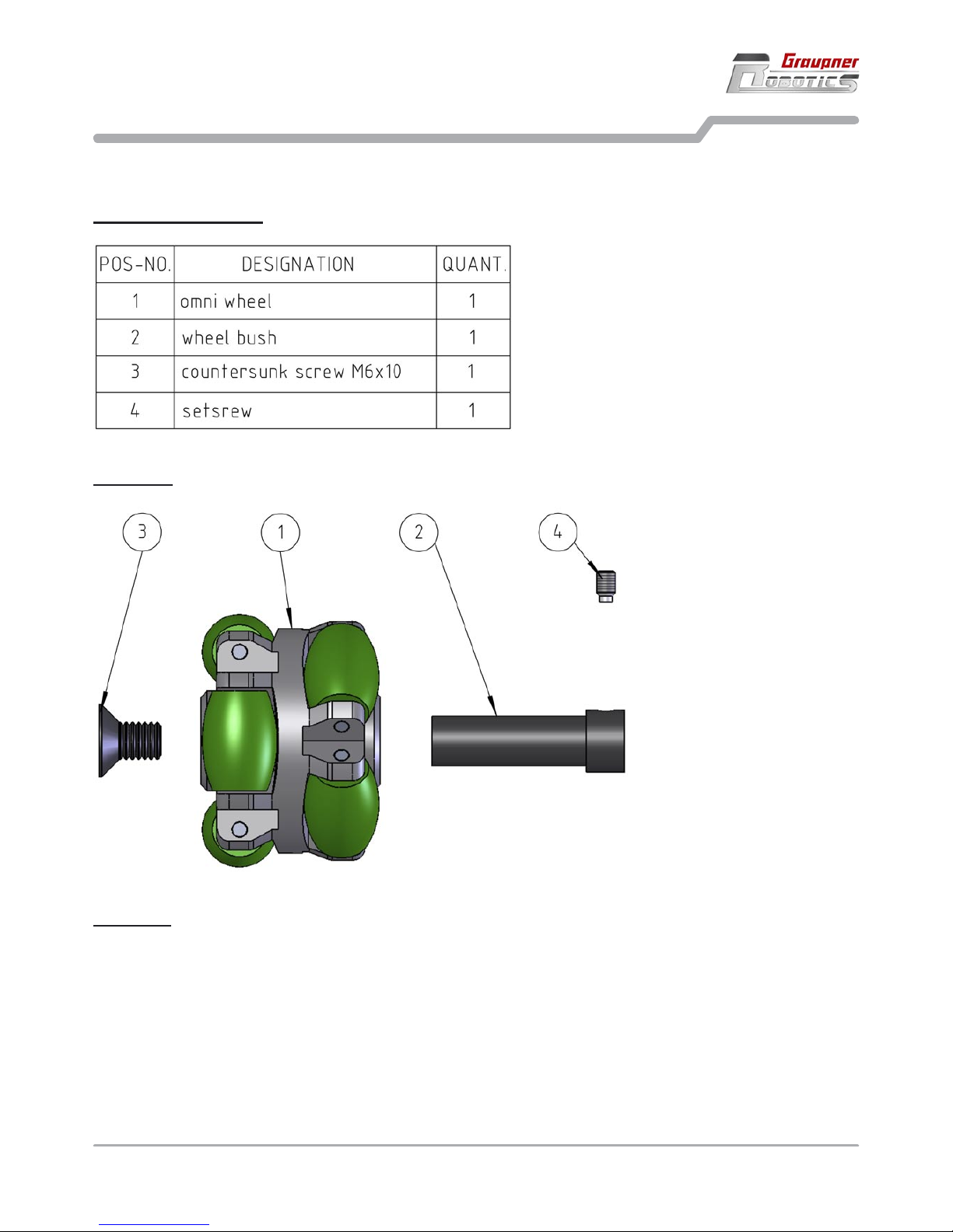
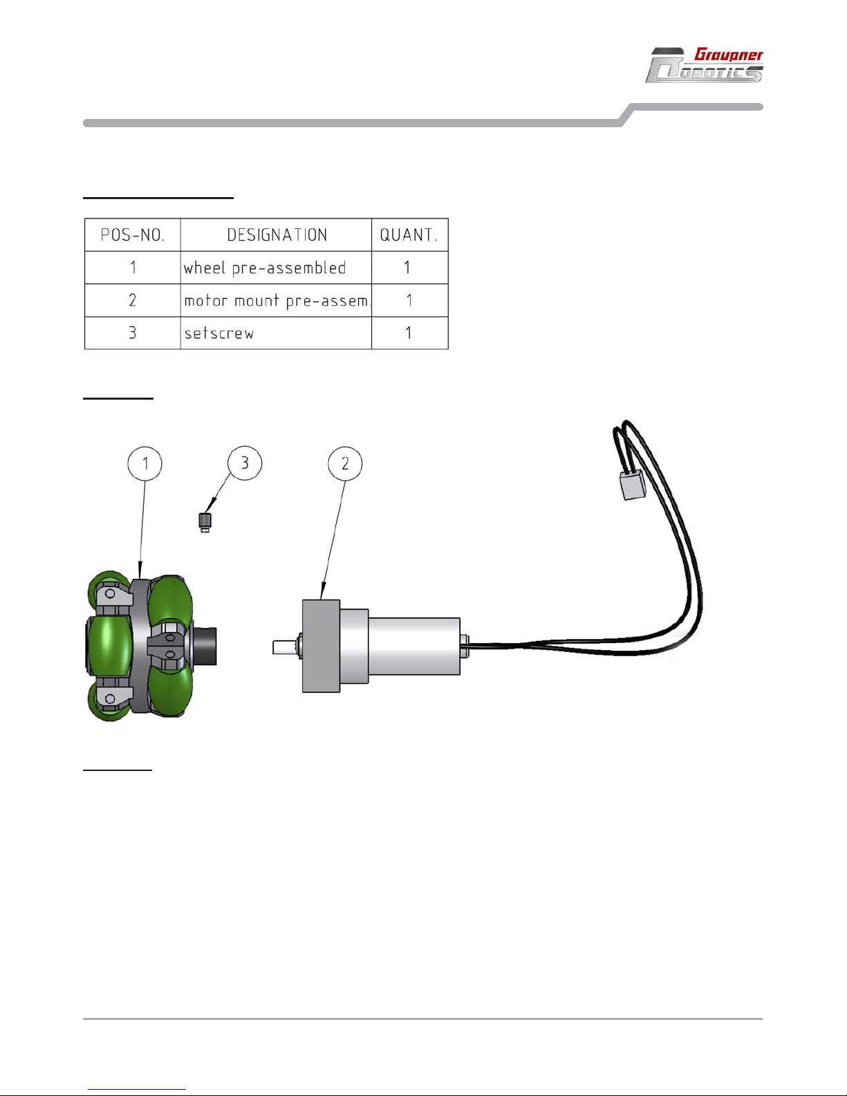
3.1 Assembling the wheels
3. Assembling the RC-SOCCERBOT
6 Assembling the RC-SOCCERBOT - Assembling the wheels
3.1 Assembling the wheels
Required components
How to do
Screw the setscrew (4) into the wheel bush (2).
Push the wheel bush (2) as far as possible into the omni wheel (1).
Fix the inserted wheel bush (2) using the countersunk (3).
Because altogether three of these wheels are required, must be repeated these assembly steps yet
twice.
•
•
•
•
Procedure
Page 7
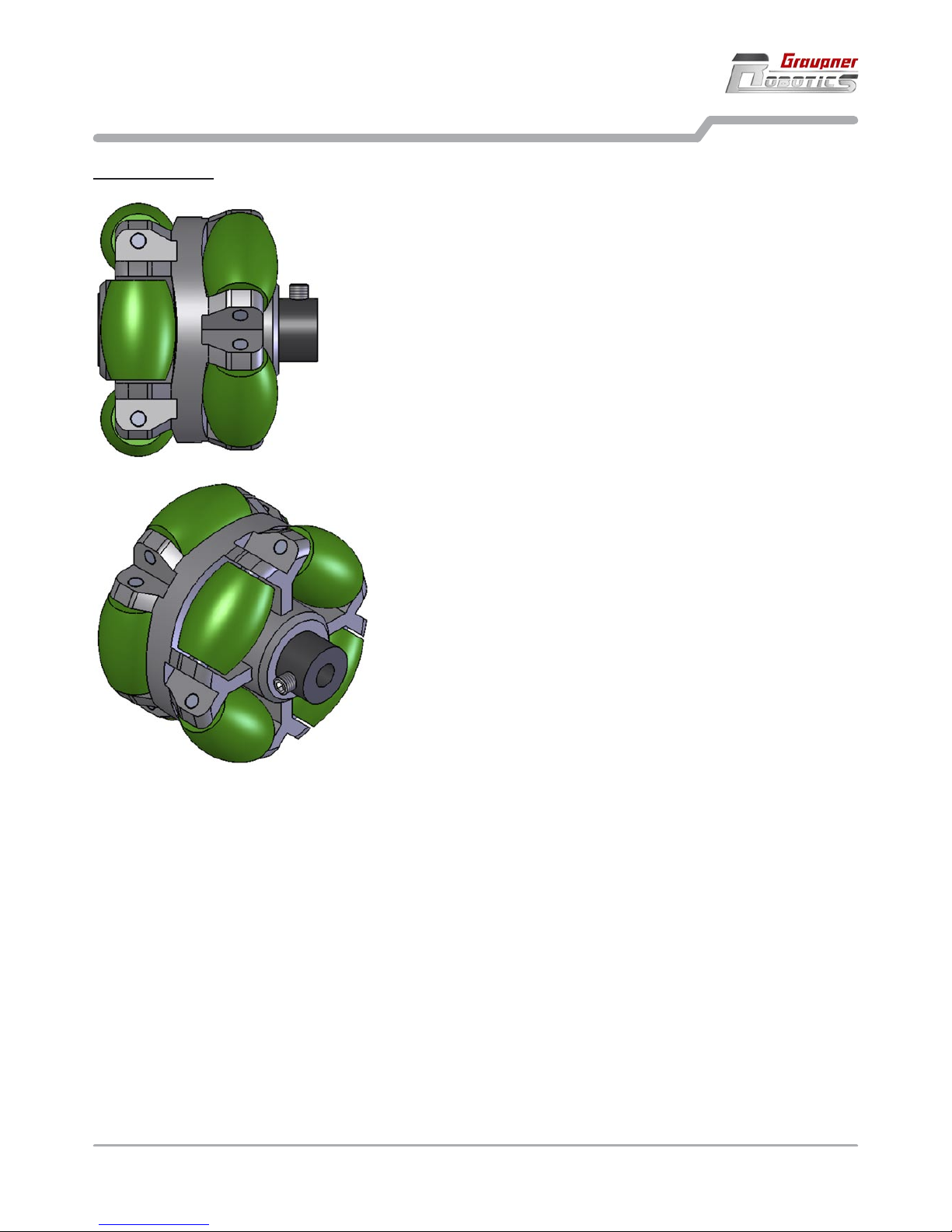
3.1 Assembling the wheels
3. Assembling the RC-SOCCERBOT
Assembling the RC-SOCCERBOT - Assembling the wheels 7
Ready mounted
Page 8
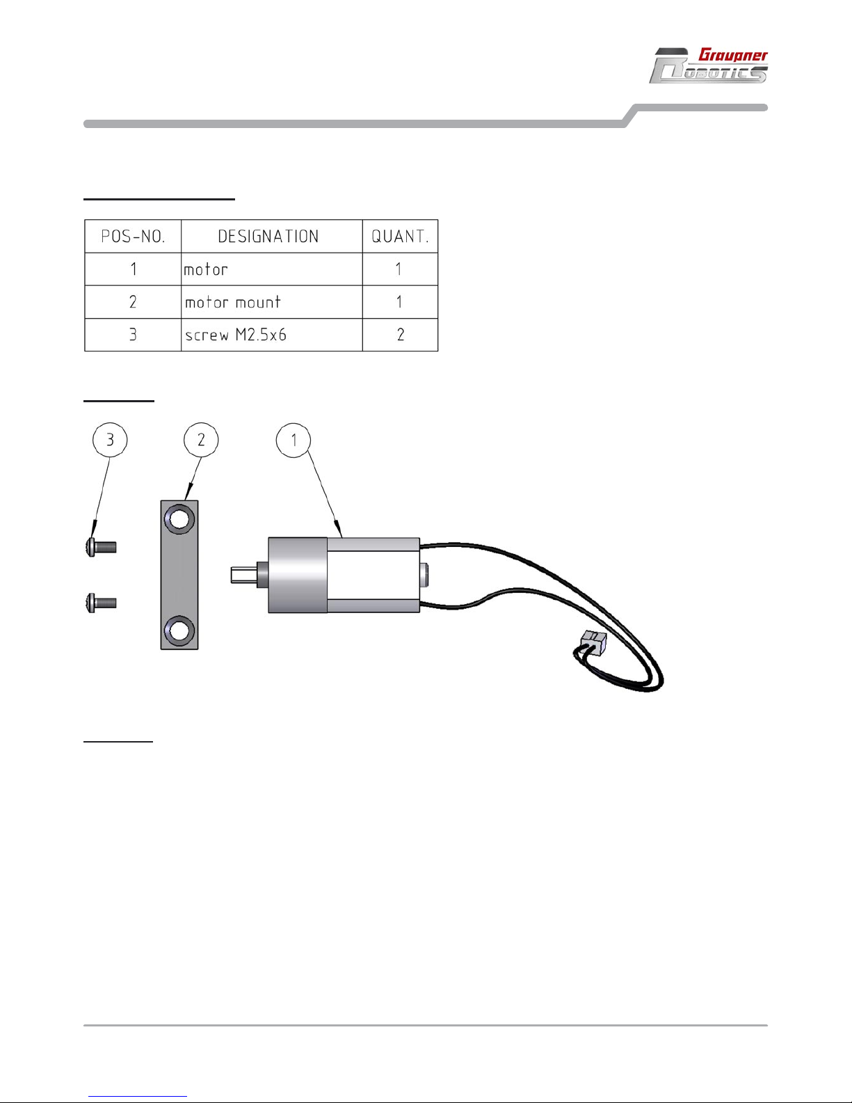
3.2 Prepare the motors
3. Assembling the RC-SOCCERBOT
3.2 Prepare the motors
Required components
8 Assembling the RC-SOCCERBOT - Prepare the motors
Procedure
How to do
Push in motor (1) into the suitable, round opening of the motor mount (2).
Fix the pushed in motor (1) and the motor mount (2) by using 2x screw (3).
Because altogether three of these motors are required, must be repeated these assembly steps yet
twice.
•
•
•
Page 9
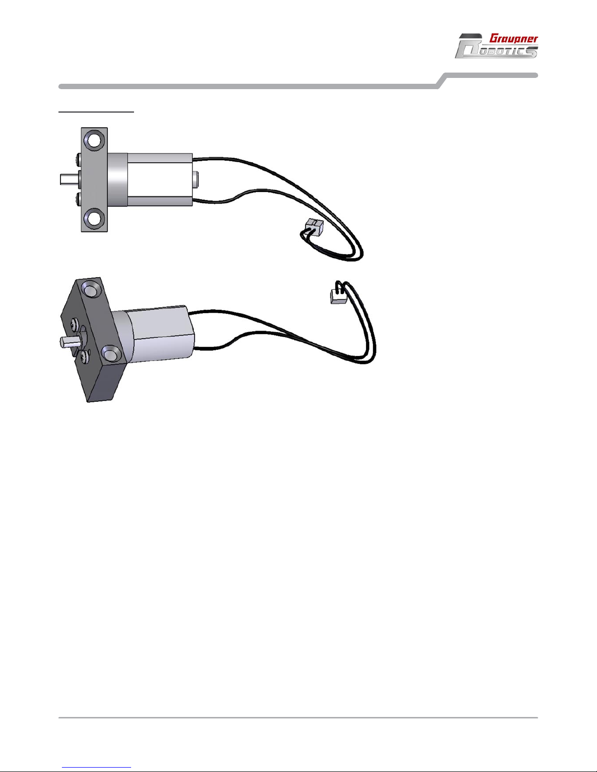
3.2 Prepare the motors
3. Assembling the RC-SOCCERBOT
Assembling the RC-SOCCERBOT - Prepare the motors 9
Ready mounted
Page 10
3.3 Assembling the drive unit
3. Assembling the RC-SOCCERBOT
10 Assembling the RC-SOCCERBOT - Assembling the drive unit
3.3 Assembling the drive unit
Required components
Procedure
How to do
Remove the mounted setscrew (3) from the wheel bush of the omni wheel (1).
Push the bush of the omni wheel (1) to the shift of the motor mount (2).
Screw in the setscrew again into the wheel bush of the omni wheel (1) and fix therewith the motor shaft.
Note that the setscrew (3) encounters on the flattened out side of the motor shaft.
Because altogether three of these wheels are required, must be repeated these assembly steps yet
twice.
•
•
•
•
Page 11
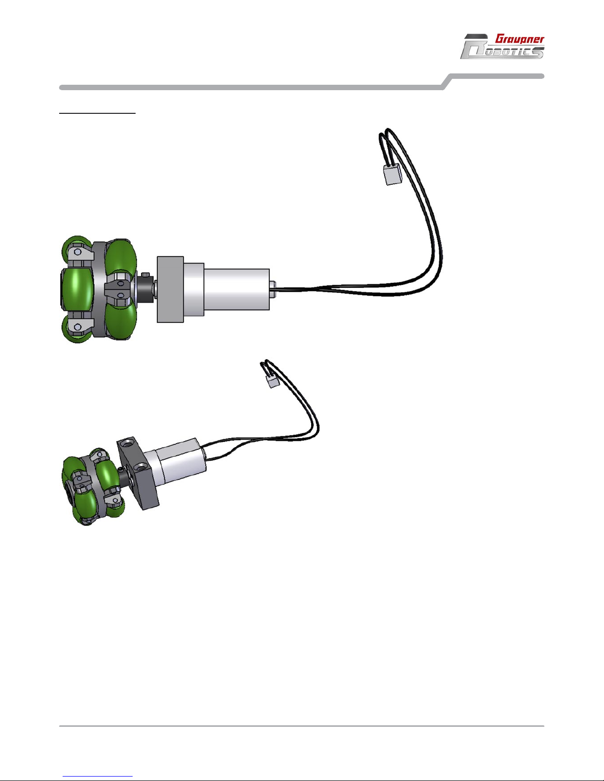
Assembling the RC-SOCCERBOT - Assembling the drive unit 11
3.3 Assembling the drive unit
3. Assembling the RC-SOCCERBOT
Ready mounted
Page 12

3.4 Assembling the striker
3. Assembling the RC-SOCCERBOT
3.4 Assembling the striker
Required components
12 Assembling the RC-SOCCERBOT - Assembling the striker
Procedure
How to do
Mount the spring (4) on the round mobile part of the striker mechanics (2).
Push the round mobile part of the striker mechanics (2) into the magnet (1).
Fix the magnet (1) to the striker mechanics (2) by using 4x screw (3).
•
•
•
Page 13

3.4 Assembling the striker
3. Assembling the RC-SOCCERBOT
Assembling the RC-SOCCERBOT - Assembling the striker 13
Ready mounted
Page 14

3.5 Mounting the spacers and drive units
3. Assembling the RC-SOCCERBOT
14 Assembling the RC-SOCCERBOT - Mounting the spacers and drive units
3.5 Mounting the spacers and drive units
Required components
Procedure
Page 15

How to do
Fix the 4x spacer (3) on the base plate (1) by using 4x screw (2).
Fix the 3x drive unit (4) on the underside of the base plate by using 6x screw (5).
•
•
3.5 Mounting the spacers and drive units
3. Assembling the RC-SOCCERBOT
Assembling the RC-SOCCERBOT - Mounting the spacers and drive units 15
Ready mounted
Page 16

3.6 Mounting the striker to the drive platform
3. Assembling the RC-SOCCERBOT
3.6 Mounting the striker to the drive platform
Required components
16 Assembling the RC-SOCCERBOT - Mounting the striker to the drive platform
Procedure
Page 17

How to do
Fix the 4x spacer (2) on the drive platform (1) by using 4x screw (3).
Fix the striker (4) on the 4x spacer (2) by using 4x screw (3).
•
•
3.6 Mounting the striker to the drive platform
3. Assembling the RC-SOCCERBOT
Assembling the RC-SOCCERBOT - Mounting the striker to the drive platform 17
Ready mounted
Page 18

3.7 Attaching the controllerboard
3. Assembling the RC-SOCCERBOT
18 Assembling the RC-SOCCERBOT - Attaching the controllerboard
3.7 Attaching the controllerboard
Required components
Procedure
How to do
Fix the controllerboard (2) on the spacers of the drive platform (1) by using 4x screw (3).•
Page 19

Ready mounted
3.7 Attaching the controllerboard
3. Assembling the RC-SOCCERBOT
Assembling the RC-SOCCERBOT - Attaching the controllerboard 19
Page 20

3.8 Connecting the actuators
3. Assembling the RC-SOCCERBOT
3.8 Connecting the actuators
Procedure
20 Assembling the RC-SOCCERBOT - Connecting the actuators
How to do
Lead the motor cables (black marked) through the larger borings of the drive platform towards the controllerboard.
Connect the cable of motor „front left“ to the bushing „Mo0“ of the controllerboard, note at the same time
the encoding of connector and bushing.
Connect the cable of motor „front right“ to the bushing „Mo1“ of the controllerboard, note at the same time
the encoding of connector and bushing.
Connect the cable of motor „back“ to the bushing „Mo2“ of the controllerboard, note at the same time the
encoding of connector and bushing.
Connect the cable of the striker (red marked) to the bushing „Mo5“ of the controllerboard, note at the
same time the encoding of connector and bushing.
•
•
•
•
•
Page 21

3.8 Connecting the actuators
3. Assembling the RC-SOCCERBOT
Assembling the RC-SOCCERBOT - Connecting the actuators 21
Ready mounted
Page 22

3.9 Mounting the power supply cables
3. Assembling the RC-SOCCERBOT
3.9 Mounting the power supply cables
Required components - (Battery (3) not included in the kit)
22 Assembling the RC-SOCCERBOT - Mounting the power supply cables
Page 23

3.9 Mounting the power supply cables
3. Assembling the RC-SOCCERBOT
Assembling the RC-SOCCERBOT - Mounting the power supply cables 23
How to do
Lead the charging jack (1) through the corresponding, larger boring of the drive platform and screw from
above.
•
Stick main switch (2) from above through the boring next to the charging jack (1) and screw from below. •
The red and black cable of the main switch (2) is connected with the cables of the charging jack (1), pay
attention at the same time to the correct color encoding.
The smaller white cable of the main switch (2) is connected with the controllerboard, note at the same
time the encoding of connector and bushing.
Finally a rechargeable battery can be connected for the power supply. The battery is not included in the
kit, we recommend Order No. R7100 - battery 2 x 6-NiMH1100, 7.2 V / 1.1 Ah.
•
•
•
Page 24

3.10 Fixing the plastic cover
3. Assembling the RC-SOCCERBOT
24 Assembling the RC-SOCCERBOT - Fixing the plastic cover
3.10 Fixing the plastic cover
Required components
Procedure
Page 25

3.10 Fixing the plastic cover
3. Assembling the RC-SOCCERBOT
Assembling the RC-SOCCERBOT - Fixing the plastic cover 25
How to do
First of all the plastic cover must be freed by the fabrication contingent edges. This can take place for
example by means of some scissors. Note to cut the designations exactly along. First cut at the lower
edge along in a circle around the plastic cover. After that the cuts of the wheels and the striker are made.
Make the four holes for the metal clips best with a hole puncher at the prescribed designations. Finally
are processed the cutting edges with a fine sandpaper.
Now the plastic cover (2) can be mounted on the drive platform (1) and can be fixed by using
4x metal clip (3).
•
•
Page 26

3.10 Fixing the plastic cover
3. Assembling the RC-SOCCERBOT
26 Assembling the RC-SOCCERBOT - Fixing the plastic cover
Ready mounted
Page 27

Assembling the RC-SOCCERBOT - Fixing the plastic cover 27
3.10 Fixing the plastic cover
3. Assembling the RC-SOCCERBOT
Comments
The plastic cover can now be labeled or painted. Examples for such decal sheets can be found in the download area of the homepage www.graupner-robotics.com.
Page 28

4. Using the RC-SOCCERBOT
Introduction
The RC-SOCCERBOT can be used with a RC transmitter or can be used as an “autonomous robot“ with free
programming on the PC. Both possibilities are briefly described in this chapter. For both possibilities and for
the power supply additional components are required
4.1 Power supply
Power supply and charging
Order No. R7100 - 2 x 6-NiMH1100 battery, 7.2 V / 1.1 Ah
Order No. R7001 - Plug-type battery charger, 7.2 V, 120 mA
4.2 Radio control
Radio control
Operate the robot forward, reverse, left / right turn, rotation, power shot and also with own, new movement
sequences by using transmitter and receiver.
Order No. R9100 - RB14SCAN 40 MHz receiver.
Order No. 4725 - Transmitter mc-12 40 MHz or any GRAUPNER/JR 40 MHz stick transmitter with at least
six functions.
The required adapter cable for connecting the receiver to the controllerboard comes in the RC-SOCCERBOT
box.
The adapter cable is connected with the receiver cable and the white plug is connected to the input „Digital
7“. The receiver is sticked to the base plate with velcro or double tape, best. The antenna cable can be laid
inside the robot or laid outside through the plastic cover using a plastic tube. The antenna cable has to be
laid with distance to the motors!
The basic programm for radio control is already preinstalled on the controllerboard, so that you can use the
robot immediately after powering on. The left remote control stick moves the robot to the front, back, left and
right. The right stick lets the robot rotate in place and activate the striker. The directions of the sticks can vary
according to attitudes of the transmitter. Read in addition the operation instructions of the transmitter.
This basic program can be found on the CD or under www.graupner-robotics.com. Please have a look to
download further programs.
28 Using the RC-SOCCERBOT - Power supply - Radio control
4.1 Power supply
4.2 Radio control
Page 29

Using the RC-SOCCERBOT - Programming the robot on the PC - Specification and Conformity 29
4. Using the RC-SOCCERBOT
4.3 Programming the robot on the PC
4.3 Programming the robot on the PC
Programming the robot on the PC
Develop new functions for the radio control or completely other software solutions for instance the line following in the C++ computer language.
Beginning programmers can use a type of flow chart to create new sequences!
Order No. R7300 - Programming set with parallel download cable
Order No. R7310 - USB download adapter
Order No. R1001.110 - Training / Teacher accompanying book with a lot of examples!
See our online shop to order extremely many accessorie parts to create different programs and software
solutions.
In the teacher accompanying book you will find different practices with solutions for the programming and
handling.
4.4 Specification and Conformity
Specification
Diameter approx. 210 mm
Height with plastic cover approx. 170 mm
Weight approx. 1000 g
Dimensions of CPU board approx. 48 x 98 x 15 mm
EU conformity declaration
Graupner GmbH & Co. KG, Henriettenstrasse 94 - 96, D-73230 Kirchheim/Teck, Germany, hereby confirms
that the RC-SOCCERBOT kit, in the version distributed by the company, fulfils the requirements of the harmonised EU directives when assembled exactly as described in these instructions. This declaration is invalidated if the device is modified in any way without our authorisation.
This product conforms to RoHS.
4.4 Specification and Conformity
Page 30

30 Controllerboard
5. Controllerboard
Controller
Atmel ATmega128 controller.
16 MHz clock for 16 mio. instructions per second.
128 KB Flash memory for own programs.
4 KB RAM memory for data.
4 KB EPROM for non-volatile data.
I²C bus for extensions (e.g. LC-display, ...).
I/O ports
2 x on-board buttons.
2 x on-board LEDs .
8 x analog inputs for analog sensors (e.g. distance sensors, line sensors).
8 x digital inputs for digital sensors (e.g. buttons, bumper, emergency OFF).
6 x motor outputs (forward/reverse 255 increments each), typically for DC motors up to 600 mA.
The inputs can be switched as outputs at the TTL level by software.
Further data
Power requirement: 7 - 12V
Self-resetting fuse
Buttons
•
•
•
•
•
•
•
•
•
•
•
•
•
•
8 analog input
6 motor output
I²C bus
download
plug
fuse
power
connector
power
LED
2 button
2 LED
controller
ATmega128
8 digital
input
Button Controller pin
T0 PG4
T1 PG3
8 power output
Page 31

Controllerboard 31
Sensor input
The switchable output provide 5V at max. 100 mA.
5. Controllerboard
+5V (switchable)
Signal
GND (ground)
Plug 5V output Signal
An0 PC0 PF0
An1 PC1 PF1
An2 PC2 PF2
An3 PC3 PF3
An4 PF4
An5 PF5
An6 PF6
An7 PF7
Di0 PC4 PA0
Di1 PC5 PA1
Di2 PC6 PE2
Di3 PC7 PE3
Di4 PE4
Di5 PE5
Di6 PE6
Di7 PE7
LEDs
LED Controller pin
L0 PB0
L1 PB2
I²C bus
Bus pin Controller pin
1 SDA PC1
4 SCL PC0
1 SDA (data)
2 Vcc (power)
3 GND (ground)
4 SCL (clock)
Download plug
IDC-6 standard by Atmel
Plug pin Controller pin
1 MISO PB6
3 SCK PB7
4 MOSI PB5
5 Reset RESET
1 MISO
2 Vcc (5V)
3 SCK
4 MOSI
5 Reset
6 GND (ground)
Page 32

Wi r ge w äh r en a uf d ie s e s E rze u gn i s e i ne / T his pr o duc t is / Su r ce pro d ui t no u s a c cor d on s un e
Garantie von
warrantied for
garantie de
2 4
Monaten
month
mois
Die Fa. Graupner GmbH & Co. KG, Henriettenstraße, 94-96 73230 Kirchheim/Teck gewährt ab dem
Kaufdatum auf dieses Produkt eine Garantie von 24
Monaten.
Die Garantie gilt nur für die bereits beim Kauf des
Produktes vorhandenen Material- oder Funktionsmängel. Schäden die auf Abnützung, Überlastung,
falsches Zubehör oder unsachgemäße Behandlung
zurückzuführen sind, sind von der Garantie ausgeschlossen.
Die gesetzlichen Rechte und Gewährleistungsansprüche des Verbrauchers werden durch diese Garantie nicht berührt.
Bitte überprüfen Sie vor einer Reklamation oder
Rücksendung das Produkt genau auf Mängel, da
wir Ihnen bei Mängelfreiheit die entstandenen Unkosten in Rechnung stellen müssen.
Graupner GmbH & Co. KG, Henriettenstraße 9496, 73230 Kirchheim/Teck, Germany guarantees
this product for a period of 24 months from date of
purchase.
The guarantee applies only to such material or
operational defects witch are present at the time of
purchase of the product.
Damage due to wear, overloading, incompetent
handling or the use of incorrect accessories is not
covered by the guarantee.
The user´s legal rights and claims under garantee
are not affected by this guarantee.
Please check the product carefully for defects before you are make a claim or send the item to us,
since we are obliged to make a charge for our cost
if the product is found to be free of faults.
La société Graupner GmbH & Co. KG, Henriettenstraße 94-96, 73230 Kirchheim/Teck, Allemagne,
accorde sur ce produit une garantie de 24 mois à
partir de la date d´achat.
La garantie prend effet uniquement sur les vices de
fonctionnement et de matériel du produit acheté.
Les dommages dûs à de l´usure, à de la surcharge,
à de mauvais accessoires ou à d´une application
inadaptée, sont exclus de la garantie.Cette garantie
ne remet pas en cause les droits et prétentions légaux du consommateur.
Avant toute réclamation et tout retour du prouit, veuillez s.v.p. cotrôler et noter exactement les défauts ou
vices du produit, car tout autre frais relatif au produit
vous sera facturé.
Servicestellen / Service / Service après-vente
Graupner-Zentralservice
Graupner GmbH & Co. KG
Postfach 1242
D-73220 Kirchheim
Servicehotline
(+49)(01805) 472876
Montag - Freitag 9:30 -11:30
und 13:00 -15:00 Uhr
Espana
FA - Sol S.A.
C. Avinyo 4
E 8240 Manresa
(+34) 93 87 34 23 4
France
Graupner France
Gérard Altmayer
86, rue ST. Antoine
F 57601 Forbach-Oeting
(+33) 3 87 85 62 12
Italia
GiMax
Via Manzoni, no. 8
I 25064 Gussago
(+39) 03 0 25 22 73 2
Sverige
Baltechno Electronics
Box 5307
S 40227 Göteborg
(+46) 31 70 73 00 0
Schweiz
Graupner Service
Wehntalerstr. 37
CH 8181 Höri
(+41) 43 26 66 58 3
UK
GLIDERS
Brunel Drive
Newark, Nottinghamshire
NG24 2EG
(+44) 16 36 61 05 39
Ceská Republika/Slovenská
Republika
RC Service Z. Hnizdil
Letecka 666/22
CZ-16100 Praha 6 - Ruzyne
(+42) 2 33 31 30 95
Luxembourg
Kit Flammang
129, route d’Arlon
L 8009 Strassen
(+35) 23 12 23 2
Belgie/Nederland
Jan van Mouwerik
Slot de Houvelaan 30
NL 3155 Maasland VT
(+31)10 59 13 59 4
Garantie-Urkunde
Warranty certificate / Certificat de garantie
Robot RC-SOCCERBOT Order No. R1001
Übergabedatum, Date of purchase/delivery, Date de remise
Name des Käufers, Owner´s name, Nom de l´acheteur
Strasse, Wohnort, Complete adress, Domicie et rue
Firmenstempel und Unterschrift des Einzelhändlers, Stamp and signature of
dealer, Cachet de la f irme et signature du detailant
32 Guarantee
Page 33

Notes 33
Notes
Page 34

© 2007 by GRAUPNER GmbH & Co. KG,
Henriettenstr. 94-96, D-73230 Kirchheim/Teck Germany
eMail: info@graupner.de
Internet: www.graupner-robotics.com
PN.KK-01
 Loading...