

Page 1
1
GRAUPNER GmbH & Co. KG D-73230 KIRCHHEIM/TECK GERMANY
Keine Haftung für Druckfehler. Technische Änderungen vorbehalten! 04/2007
ID# 0057887
Montageanleitung für das Modell PITTS S12 1400, Best.-Nr. 9570
Beschreibung des Modells
Die GRAUPNER PITTS S12 1400 ist ein Nachbau des amerikanischen
Kunstflugdoppeldeckers. Das Modell ist voll kunstflugtauglich und lässt sich über alle drei
Achsen steuern. Sowohl im Freien als auch in der Halle sind nur dem Können des Piloten
Grenzen gesetzt. Durch große Ruderklappen können auch extreme 3D-Flugfiguren geflogen
werden.
Technische Daten
Spannweite ca. 1400 mm
Länge ü.a. ca. 1510 mm
Flächeninhalt ca. 71,1 dm²
Flächenbelastung ca. 21,6 g/dm²
Fluggewicht je nach
Ausrüstung 1540g
Page 2

2
GRAUPNER GmbH & Co. KG D-73230 KIRCHHEIM/TECK GERMANY
Keine Haftung für Druckfehler. Technische Änderungen vorbehalten! 04/2007
ID# 0057887
Wichtige Sicherheitshinweise
Sie haben einen Bausatz erworben, aus dem – zusammen mit entsprechendem geeignetem Zubehör – ein funktionsfähiges
RC-Modell fertiggestellt werden kann. Die Einhaltung der Montage- und Betriebsanleitung im Zusammenhang mit dem
Modell sowie die Installation, der Betrieb, die Verwendung und Wartung der mit dem Modell zusammenhängenden
Komponenten können von GRAUPNER nicht überwacht werden. Daher übernimmt GRAUPNER keinerlei Haftung für
Verluste, Schäden oder Kosten, die sich aus dem fehlerhaften Betrieb, aus fehlerhaftem Verhalten bzw. in irgendeiner
Weise mit dem Vorgenannten zusammenhängend ergeben. Soweit vom Gesetzgeber nicht zwingend vorgeschrieben, ist die
Verpflichtung der Firma GRAUPNER zur Leistung von Schadensersatz, aus welchem Grund auch immer ausgeschlossen
(inkl. Personenschäden, Tod, Beschädigung von Gebäuden sowie auch Schäden durch Umsatz- oder Geschäftsverlust,
durch Geschäftsunterbrechung oder andere indirekte oder direkte Folgeschäden), die von dem Einsatz des Modells
herrühren.
Die Gesamthaftung ist unter allen Umständen und in jedem Fall beschränkt auf den Betrag, den Sie tatsächlich für dieses
Modell gezahlt haben.
Die Inbetriebnahme und der Betrieb des Modells erfolgt einzig und allein auf Gefahr des Betreibers. Nur ein
vorsichtiger und überlegter Umgang beim Betrieb schützt vor Personen- und Sachschäden.
Nach der neuen Regelung des §103 Abs. 3 LuftVZO müssen alle Flugmodelle, egal ob Slowflyer, Parkflyer, Segelflugzeuge,
Flugmodelle mit Antrieben jeglicher Art vor Aufnahme des Flugbetriebs versichert sein. Schließen Sie daher eine spezielle
RC-Modell-Haftplichtversicherung ab. Fragen hierzu werden Ihnen vom Fachhandel gerne beantwortet.
Diese Sicherheitshinweise müssen unbedingt aufbewahrt werden und müssen bei einem Weiterverkauf des Modells an den
Käufer weitergegeben werden.
Herstellererklärung Fa. Graupner GmbH & Co KG,
Henriettenstr. 94 -96, D 73230 Kirchheim/Teck
Inhalt der Herstellererklärung:
Sollten sich Mängel an Material oder Verarbeitung an einem von uns in der Bundesrepublik Deutschland vertriebenen, durch
einen Verbraucher (§ 13 BGB) erworbenen Gegenstand zeigen, übernehmen wir, die Fa. Graupner GmbH & Co KG,
Kirchheim/Teck im nachstehenden Umfang die Mängelbeseitigung für den Gegenstand.
Rechte aus dieser Herstellererklärung kann der Verbraucher nicht geltend machen, wenn die Beeinträchtigung der
Brauchbarkeit des Gegenstandes auf natürlicher Abnutzung, unsachgemäßer Verwendung (einschließlich Einbau) oder
Einwirkung von außen beruht.
Diese Herstellererklärung lässt die gesetzlichen oder vertraglich eingeräumten Mängelansprüche und –rechte des
Verbrauchers aus dem Kaufvertrag gegenüber seinem Verkäufer (Händler) unberührt.
Umfang der Garantieleistung
Im Garantiefall leisten wir nach unserer Wahl Reparatur oder Ersatz der mangelbehafteten Ware. Weitergehende
Ansprüche, insbesondere Ansprüche auf Erstattung von Kosten im Zusammenhang mit dem Mangel (z.B. Ein/Ausbaukosten) und der Ersatz von Folgeschäden sind – soweit gesetzlich zugelassen – ausgeschlossen. Ansprüche aus
gesetzlichen Regelungen, insbesondere nach dem Produkthaftungsgesetz, werden hierdurch nicht berührt.
Voraussetzung der Garantieleistung
Der Käufer hat den Garantieanspruch schriftlich unter Beifügung des Originals des Kaufbelegs (z.B. Rechnung, Quittung,
Lieferschein) und dieser Garantiekarte geltend zu machen. Er hat zudem die defekte Ware auf seine Kosten an die o.g.
Adresse einzusenden. Die Einsendung hat an folgende Adresse zu erfolgen:
Fa. Graupner GmbH & CO KG, Reklamationsabteilung,
Henriettenstr.94 -96, D 73230 Kirchheim/Teck
Der Käufer soll dabei den Material- oder Verarbeitungsfehler oder die Symptome des Fehlers so konkret benennen, dass
eine Überprüfung unserer Garantiepflicht möglich wird.
Der Transport des Gegenstandes vom Verbraucher zu uns als auch der Rücktransport erfolgen auf Gefahr des
Verbrauchers.
Gültigkeitsdauer
Diese Erklärung ist nur für während der Anspruchsfrist bei uns geltend gemachten Ansprüche aus dieser Erklärung gültig.
Die Anspruchsfrist beträgt 24 Monate ab Kauf des Gerätes durch den Verbraucher bei einem Händler in der Bundesrepublik
Deutschland (Kaufdatum). Werden Mängel nach Ablauf der Anspruchsfrist angezeigt oder die zur Geltendmachung von
Mängeln nach dieser Erklärung geforderten Nachweise oder Dokumente erst nach Ablauf der Anspruchsfrist vorgelegt, so
stehen dem Käufer keine Rechte oder Ansprüche aus dieser Erklärung zu.
Page 3

3
GRAUPNER GmbH & Co. KG D-73230 KIRCHHEIM/TECK GERMANY
Keine Haftung für Druckfehler. Technische Änderungen vorbehalten! 04/2007
ID# 0057887
Verjährung
Soweit wir einen innerhalb der Anspruchsfrist ordnungsgemäß geltend gemachten Anspruch aus dieser Erklärung nicht
anerkenne, verjähren sämtliche Ansprüche aus dieser Erklärung in 6 Monaten vom Zeitpunkt der Geltendmachung an,
jedoch nicht vor Ende der Anspruchsfrist.
Anwendbares Recht
Auf diese Erklärung und die sich daraus ergebenden Ansprüche, Rechte und Pflichten findet ausschließlich das materielle
deutsche Recht ohne die Normen des Internationalen Privatrechts sowie unter Ausschluss des UN-Kaufrechts Anwendung.
Folgende Punkte müssen unbedingt beachtet werden:
Das Modell ist nicht für Kinder unter 14 Jahren geeignet. Nicht volljährige Jugendliche dürfen das Modell nur
unter der Aufsicht eines Erziehungsberechtigten betreiben.
Jeder Modellflieger hat sich so zu verhalten, dass die öffentliche Sicherheit und Ordnung, insbesondere
andere Personen und Sachen, sowie die Ordnung des Modellflugbetriebs nicht gefährdet oder gestört
wird.
Der Betreiber muss im Besitz seiner vollen körperlichen und geistigen Fähigkeiten sein. Wie beim
Autofahren, ist der Betrieb des Flugmodells unter Alkohol oder Drogeneinwirkung nicht erlaubt.
Fragen, die die Sicherheit beim Betrieb des RC-Flugmodells betreffen, werden Ihnen vom Fachhandel gerne
beantwortet.
Fernsteuer-Flugmodelle sind sehr anspruchsvolle und gefährliche Gegenstände und erfordern vom Betreiber
einen hohen Sachverstand, Können und Verantwortungsbewusstsein.
Rechtlich gesehen, ist ein Flugmodell ein Luftfahrzeug und unterliegt entsprechenden Gesetzen, die
unbedingt eingehalten werden müssen. Die Broschüre »Modellflugrecht, Paragrafen und mehr«, Best.-Nr.
8034.01, stellt eine Zusammenfassung dieser Gesetze dar; sie kann auch beim Fachhandel eingesehen
werden. Ferner müssen rechtliche Auflagen, die die Fernlenkanlage betreffen, beachtet werden.
Entsprechende Hinweise finden Sie in der Bedienungsanleitung Ihrer Fernsteueranlage.
Ein RC-Flugmodell kann nur funktionsfähig sein und den Erwartungen entsprechen, wenn es im Sinne der
Bauanleitung sorgfältigst gebaut wurde. Nur ein vorsichtiger und überlegter Umgang beim Betrieb schützt vor
Personen- und Sachschäden. Niemand würde sich in ein Flugzeug setzen und - ohne vorausgegangene
Schulung - versuchen, damit zu fliegen. Auch Modellfliegen will gelernt sein. Bitte wenden Sie sich dazu an
erfahrene Modellflieger, an Vereine oder Modellflugschulen. Ferner sei auf den Fachhandel und die
einschlägige Fachpresse verwiesen. Am besten als Club-Mitglied auf zugelassenem Modellflugplatz fliegen.
Beim erstmaligen Steuern eines Flugmodells ist es von Vorteil, wenn ein erfahrener Helfer bei der
Überprüfung und den ersten Flügen zur Seite steht.
Es dürfen nur die dem Bausatz enthaltenen Teile, sowie die ausdrücklich von uns empfohlenen Graupner
Zubehör und Ersatzteile verwendet werden.
Wird auch nur eine Komponente der Antriebseinheit geändert, ist ein sicherer Betrieb nicht mehr
gewährleistet und es erlischt jeglicher etwaiger Garantieanspruch.
Beachten Sie immer beim Einsatz und Laden der LiPo-Akkus die jeweiligen Sicherheitsvorschriften der
Akkus. Diese sind den Akkus und dem Ladegerät beigelegt.
Das Flugmodell niemals in der Nähe von Hochspannungsleitungen, Industriegelände, in Wohngebieten,
öffentlichen Straßen, Plätzen, Schulhöfen, Parks und Spielplätzen usw. fliegen lassen.
Informieren Sie alle Passanten und Zuschauer vor der Inbetriebnahme über alle möglichen Gefahren, die von
Ihrem Modell ausgehen und ermahnen diese, sich in ausreichendem Schutzabstand, wenigstens 5 m hinter
der Luftschraubenebene, aufzuhalten.
Stets mit dem notwendigen Sicherheitsabstand zu Personen oder Gegenständen fliegen; niemals Personen
in niedriger Höhe überfliegen oder auf sie zufliegen!
Betreiben Sie Ihr Modell niemals in Naturschutz- und Landschaftsschutzgebieten.
Betrieben Sie es niemals bei widrigen Witterungsbedingungen, wie z. B. Regen, Gewitter, stärkerem Wind
und Temperaturen unter –5°C oder über +35°C
Kontrollieren Sie, bevor Sie das Modell betreiben, dieses auf eine sichere Funktion der Fernsteuerung sowie
die Steckverbindungen auf sichere und feste Verbindung.
Verwenden Sie immer nur passende, verpolungssichere Steckverbindungen. Alle stromführenden
Leitungen, Steckverbindungen, sowie die Antriebsbatterie, bei Selbstkonfektionierung, kurzschlusssicher
isolieren. Kombinieren Sie niemals unterschiedliche, z. B. Blech- und Goldkontakte, da hier keine sichere
Funktion gewährleistet ist.
Die Akkus müssen vor dem Betrieb geladen werden und die Reichweite der Fernsteuerung muss überprüft
werden. Besonders der Senderakku muss vor jedem Einsatz geladen werden.
Prüfen Sie, ob der von Ihnen genutzte Kanal frei ist. Betreiben Sie Ihr Modell niemals, wenn Sie sich nicht
sicher sind, ob der Kanal frei ist. Wenn andere Modellbauer in der Nähe sind, fragen Sie diese nach dem
verwendeten Kanal.
Page 4

4
GRAUPNER GmbH & Co. KG D-73230 KIRCHHEIM/TECK GERMANY
Keine Haftung für Druckfehler. Technische Änderungen vorbehalten! 04/2007
ID# 0057887
Beachten Sie die Empfehlungen und Hinweise zu Ihrer Fernsteuerung und Zubehörteilen.
Arbeiten Sie an den Antriebsteilen nur bei abgezogener Motorstromversorgung.
Bei angeschlossenem Fahrakku dürfen Sie und andere Personen niemals in den Bereich des Propellers
kommen, da durch diese eine erhebliche Verletzungsgefahr besteht.
Die empfohlene Betriebsspannung nicht übersteigen. Eine höhere Spannung kann zum Überhitzen der
Motoren bzw. des Fahrtreglers führen oder die elektrischen Leitungen können durchschmoren. Dadurch kann
das Modell zerstört werden, da z. B. ein Schwelbrand entstehen kann.
Achten Sie auf Leichtläufigkeit aller Antriebskomponenten.
Achten Sie darauf, dass die Servos in ihrem Verfahrweg mechanisch nicht begrenzt werden.
Batterien und Akkus dürfen nicht kurzgeschlossen werden, sowie nicht direkt dem Wasser ausgesetzt
werden.
Lassen Sie den Motor und den Fahrtregler nach jeder Fahrt abkühlen. Fassen Sie die möglicherweise heißen
Teile nicht an.
Entnehmen Sie die Akkus beim Transport und Nichtgebrauch des Modells.
Setzen Sie das Modell nicht starker Luftfeuchtigkeit, Hitze, Kälte sowie Schmutz aus. Das Modell im Sommer
nicht im heißen Auto liegen lassen.
Sichern Sie das Modell und RC-Komponenten beim Transport gegen Beschädigung sowie Verrutschen.
Bringen Sie bei einer evtl. Bergung des Modells sich nicht selbst sowie andere in Gefahr.
Vor jedem Flug eine Überprüfung der kompletten RC-Anlage, sowie des Flugmodells auf volle
Funktionstüchtigkeit und Reichweite durchführen.
Dabei ist zu beachten, dass bei der Inbetriebnahme die Motorsteuerfunktion am Sender immer zuerst in
AUS-Stellung gebracht wird. Danach Sender und dann erst Empfangsanlage einschalten, um ein
unkontrolliertes Anlaufen des Elektromotors zu vermeiden. Gleichfalls gilt immer zuerst Empfangsanlage
ausschalten, danach erst den Sender.
Überprüfen Sie, dass die Ruder sich entsprechend der Steuerknüppelbetätigung bewegen.
Beim Bewegen des Querruder-Steuerknüppels nach rechts, muss das rechte Querruder nach oben und das
linke Querruder nach unten ausschlagen.
Beim Bewegen des Seitenruder-Steuerknüppels nach rechts, muss das Seitenruder, in Flugrichtung
gesehen, nach rechts ausschlagen.
Beim Bewegen des Höhen-/Tiefenruder-Knüppels nach hinten, zum Bauch, müssen beide Ruder nach oben
ausschlagen.
Beim Fliegen keine abrupten Steuerknüppelbewegungen durchführen.
Mit diesen Hinweisen soll auf die vielfältigen Gefahren hingewiesen werden, die durch unsachgemäße und
verantwortungslose Handhabung entstehen können. Richtig und gewissenhaft betrieben ist Modellflug eine
kreative, lehrreiche und erholsame Freizeitgestaltung.
Überprüfung vor dem Start
Vor jedem Einsatz korrekte Funktion und Reichweite überprüfen. Dazu Senderantenne einschrauben und dann
auf vollständige Länge ausziehen. Dann den Sender einschalten, ebenso den Empfänger. Aus entsprechendem
Abstand vom Modell kontrollieren, ob alle Ruder einwandfrei funktionieren und in der richtigen Richtung
ausschlagen.
Diese Überprüfung bei laufendem Motor wiederholen, während ein Helfer das Modell festhält.
Beim erstmaligen Steuern eines Flugmodells ist es von Vorteil, wenn ein erfahrener Helfer bei der Überprüfung und den
ersten Flügen zur Seite steht.
Material – Material Geeignete Klebstoffe
Kunststoff allgemein – Depron Styroporsekundenkleber/ UHU POR/5min Epoxy
Depron – Depron Styroporsekundenkleber/ UHU POR/5min Epoxy
Depron – Metall Styroporsekundenkleber/ UHU POR/5min Epoxy
CFK – CFK Sekundenkleber/5min Epoxy
Beachten Sie die Verarbeitungshinweise der Klebstoffe! Achten Sie auf besondere Hinweise in der
Montageanleitung über den Einsatz bestimmter Klebstoffe! Bei Verwendung von Spiritus und anderen
Lösungsmitteln als Reinigungsmittel, sind besondere Vorsichtsmaßnahmen nötig. Richten Sie sich nach den
jeweiligen Verarbeitungsrichtlinien.
Page 5
5
GRAUPNER GmbH & Co. KG D-73230 KIRCHHEIM/TECK GERMANY
Keine Haftung für Druckfehler. Technische Änderungen vorbehalten! 04/2007
ID# 0057887
Montageanleitung
1. Zur Vereinfachung und besseren Verständnis der Anleitung schneiden Sie die Stückliste und die Seite
mit den Pos.-Nr. der Laserteile aus der Anleitung, um bei den einzelnen Baustufen immer den direkten
Zugriff zu haben.
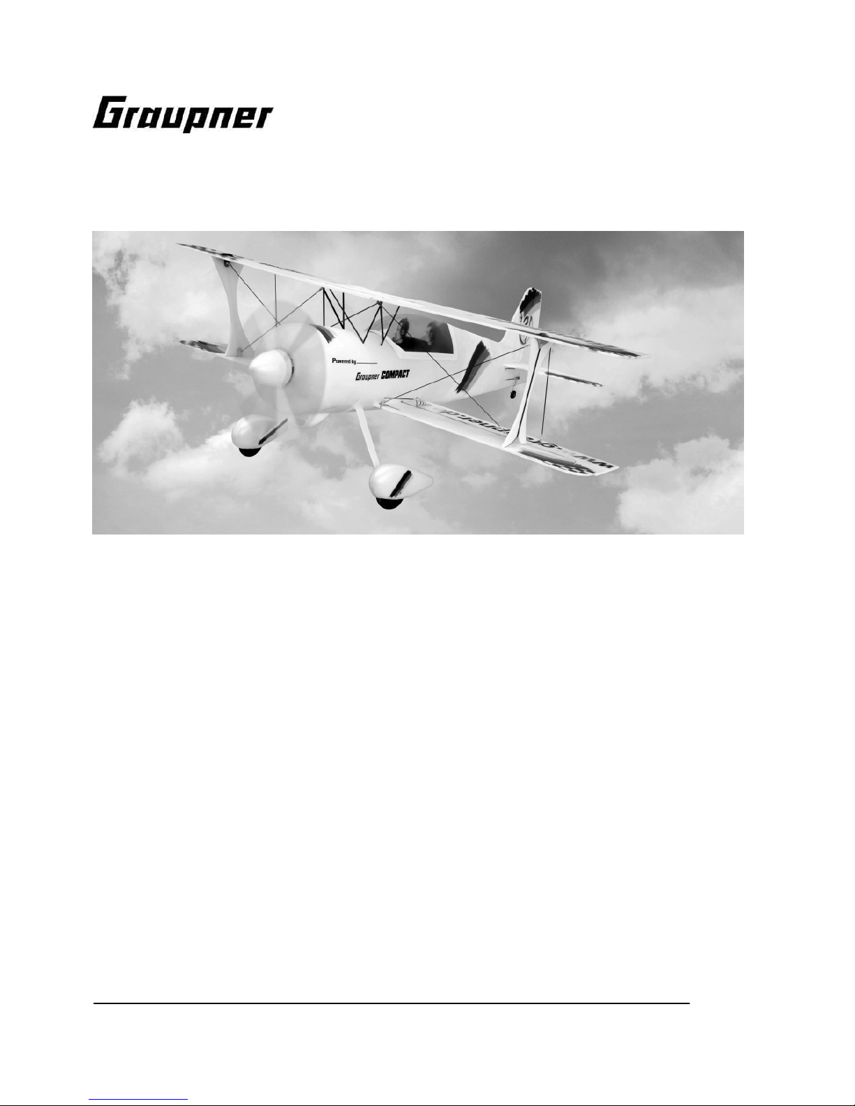
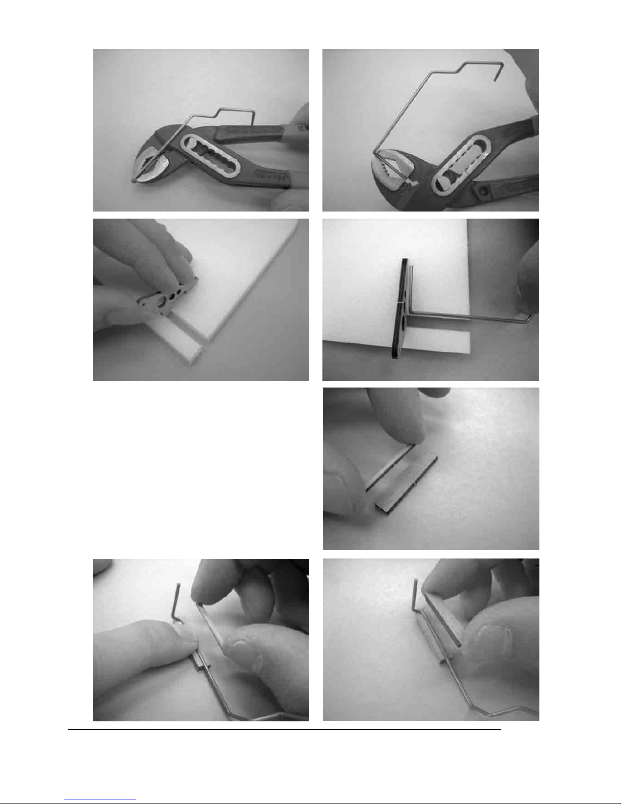
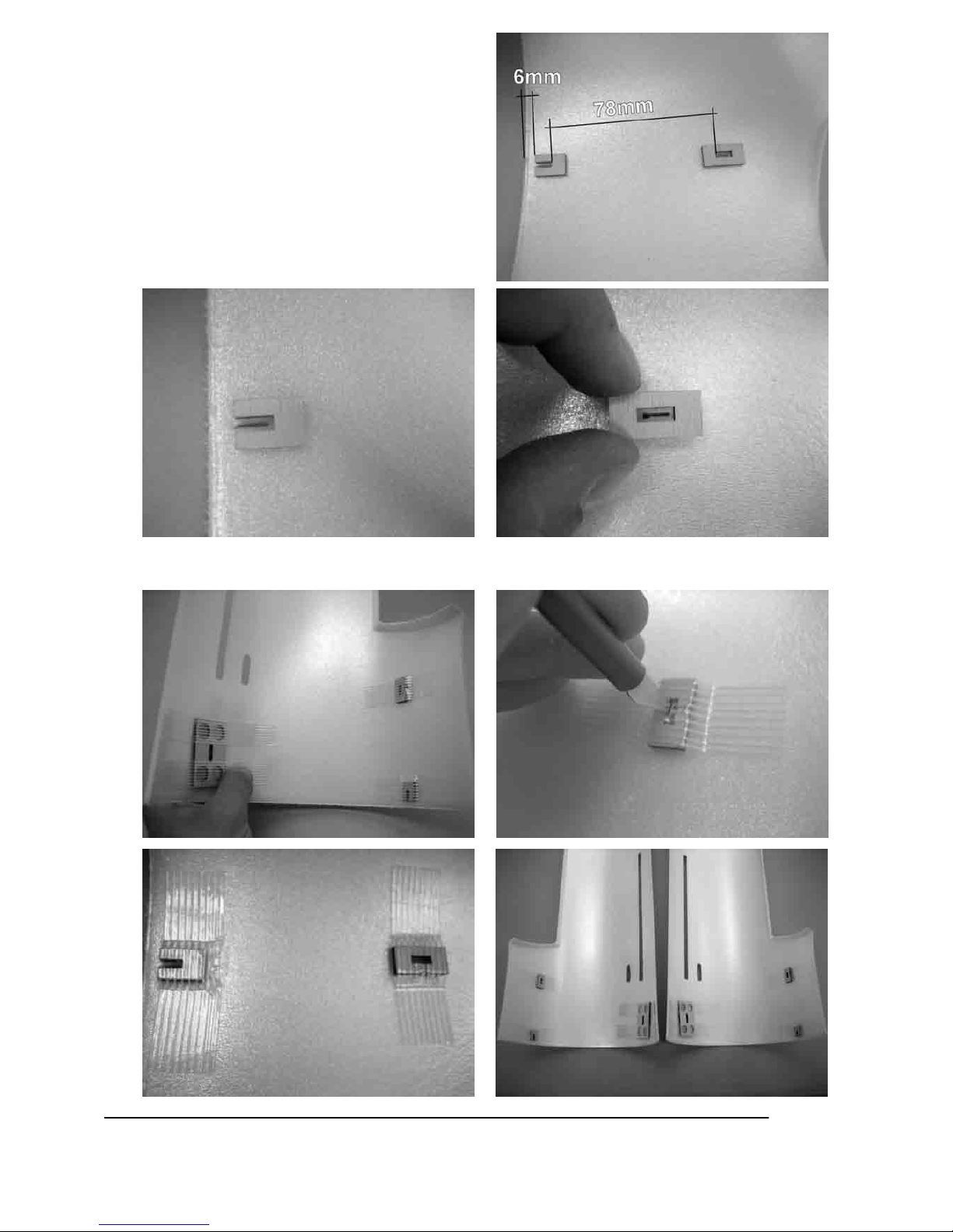
2. Als ersten Schritt längen Sie am besten alle CFKStäbe auf die in der Stückliste angegebenen
Längen ab. Beachten Sie hierbei die
Reihenfolge in der Stückliste. Für eine bessere
Verbindung der CFK-Teile, die nicht mit UHUpor verklebt werden, gilt vor dem Verkleben an
der zu verklebenden Stelle anschleifen.
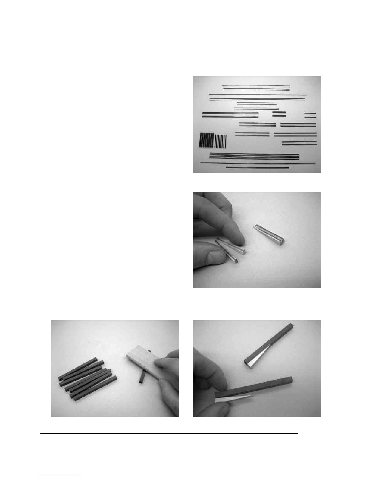
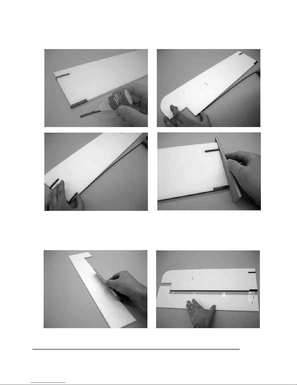
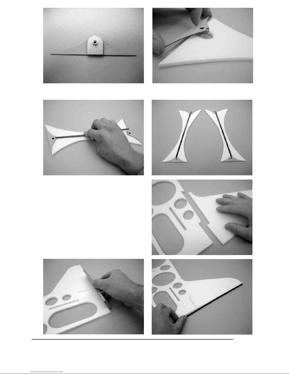
3. Verkleben Sie mit Sekundenkleber jeweils zwei
der vier Verbindungskeile (21) miteinander.
4. Schleifen Sie die Flächensteckungsrohre (7) an. Verkleben Sie die Verbindungskeile (21) bündig mit
der Endkante des Flächensteckungsrohres (7).
Page 6
6
GRAUPNER GmbH & Co. KG D-73230 KIRCHHEIM/TECK GERMANY
Keine Haftung für Druckfehler. Technische Änderungen vorbehalten! 04/2007
ID# 0057887
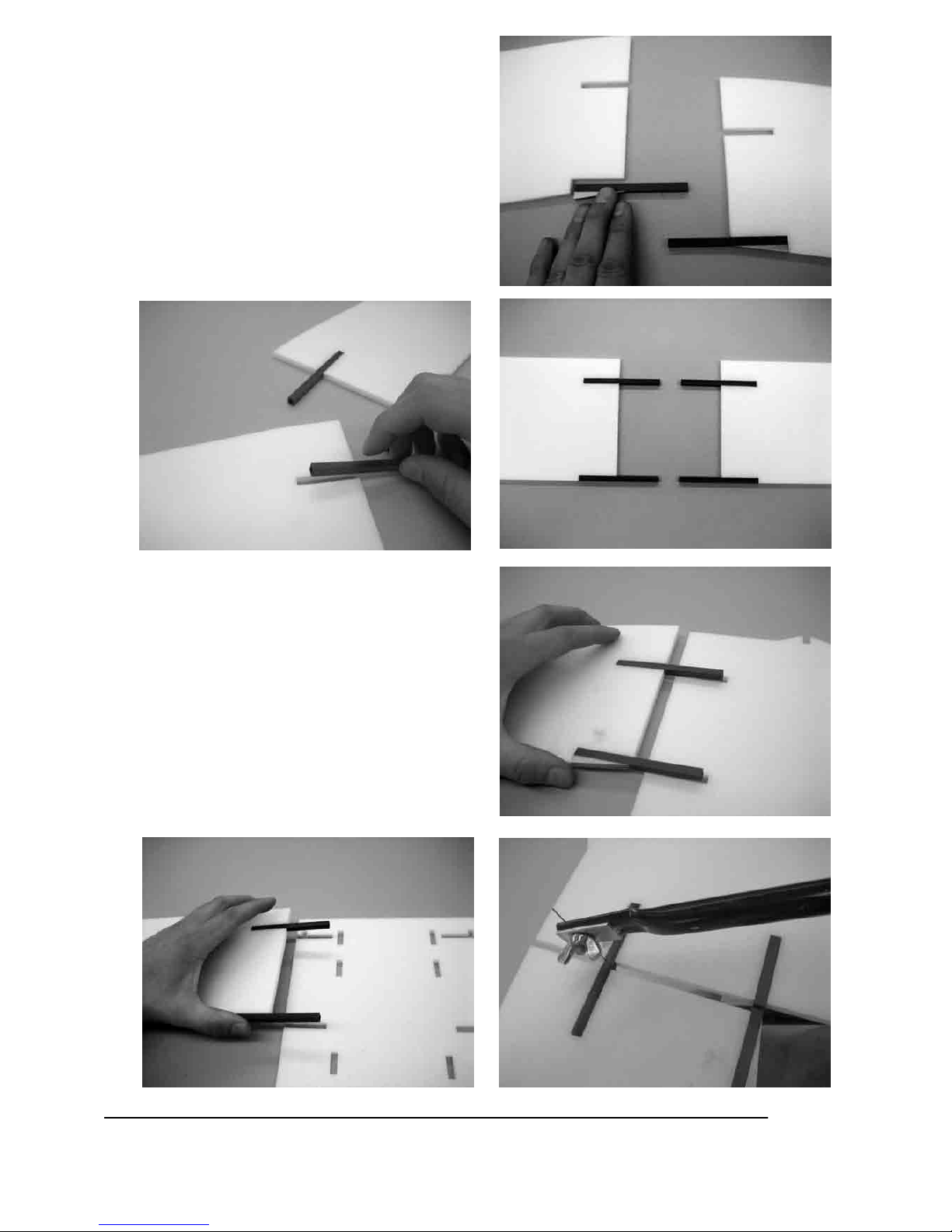
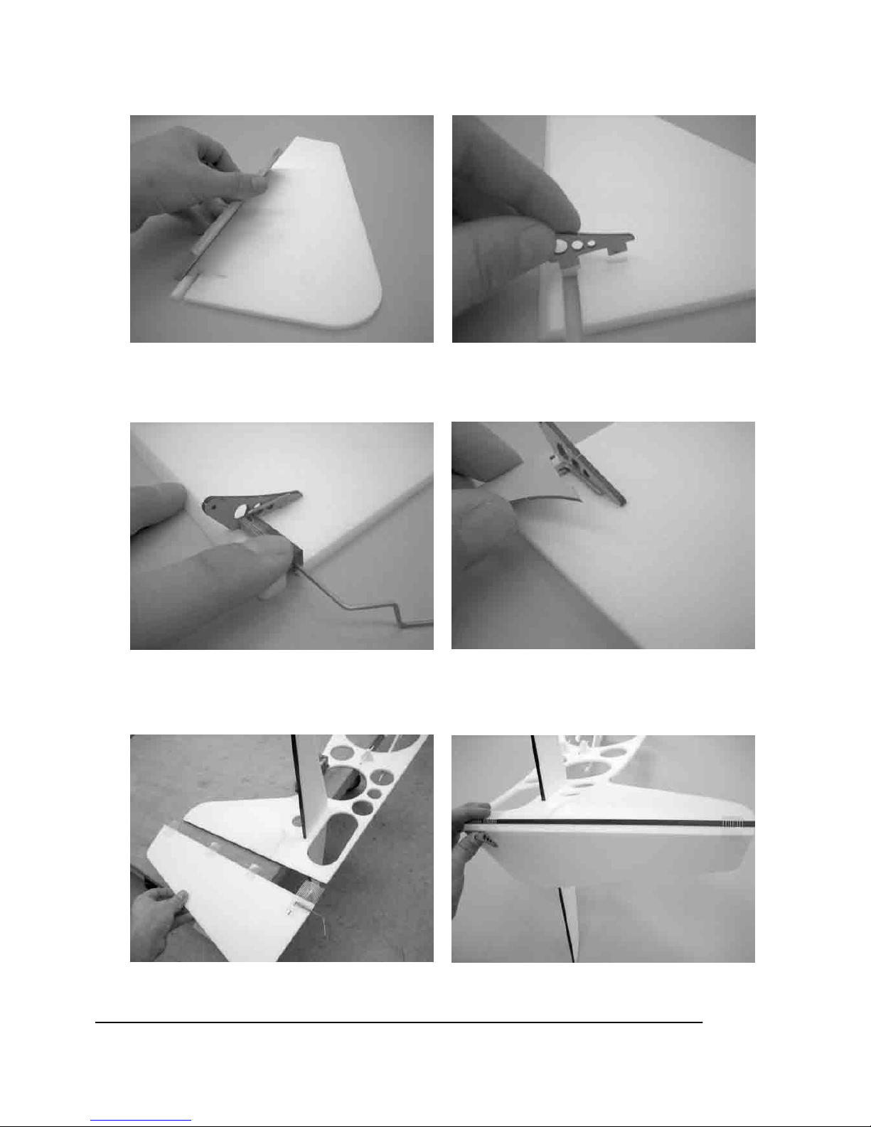
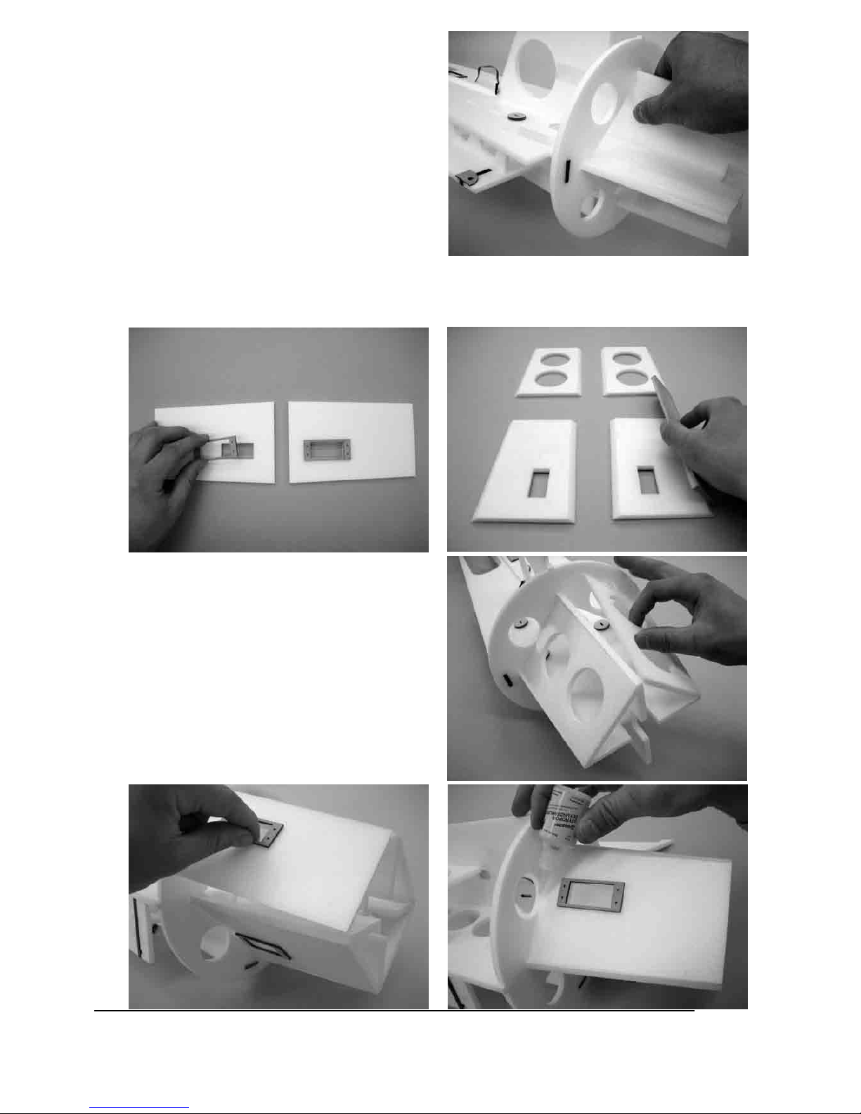
5. Kleben Sie mit 5 min Epoxy die
Flächensteckungsrohre(7) wie auf den folgenden
Bildern in die Tragflächen(22,23) ein.
6. Nun die Tragflächen mit den
Tragflächenmittelstücken (24,25) verkleben und
mit einer Laubsäge die Steckungsrohre(7) in der
Mitte durchtrennen. Die überstehenden Enden
der Steckungsrohre noch nicht bündig
schleifen, erst nach Komplettierung der
Tragflächen.
Page 7
7
GRAUPNER GmbH & Co. KG D-73230 KIRCHHEIM/TECK GERMANY
Keine Haftung für Druckfehler. Technische Änderungen vorbehalten! 04/2007
ID# 0057887
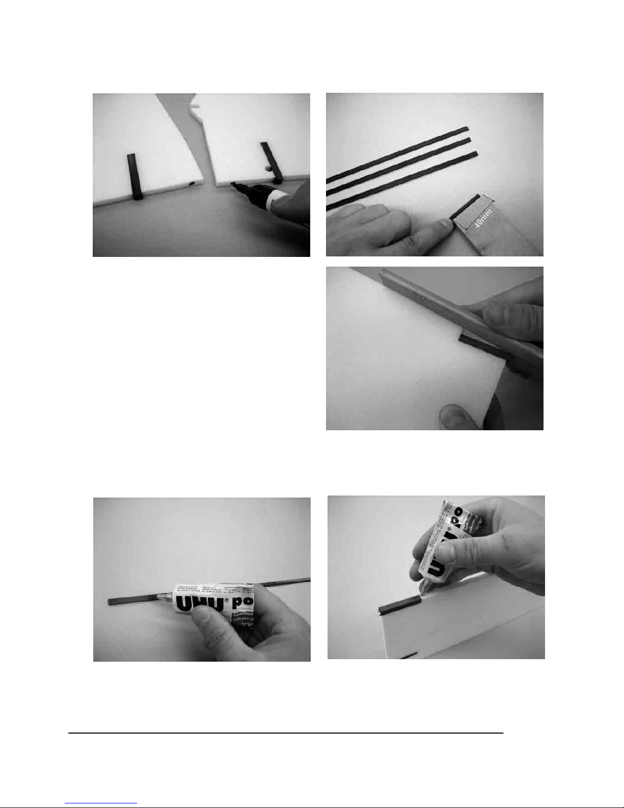
7. Kennzeichnen Sie z.B. die obere linke und die untere linke Tragfläche um später einen passgenauen
Sitz der Tragflächen zu gewährleisten. Danach schleifen Sie die Tragflächenverstärkung (14) auf einer
Seite 40mm breit an.
8. Verschleifen Sie die Verbindungskeile (21) und
das Flächensteckungsrohr (7) bündig mit der
Tragflächenendkante (nur an den oberen
Tragflächen nötig)
9. Tragflächen und Tragflächenverstärkung (14) mit UHU-por einstreichen und ablüften lassen. Darauf
achten, dass nur die nicht angeschliffenen und nur die Depron®- Teile mit UHU-por
eingestrichen werden, da die angeschliffenen Teile mit dickflüssigem Sekundenkleber verklebt
werden. Dies gilt für alle Bauschritte die diesem gleichen oder ähneln.
Page 8
8
GRAUPNER GmbH & Co. KG D-73230 KIRCHHEIM/TECK GERMANY
Keine Haftung für Druckfehler. Technische Änderungen vorbehalten! 04/2007
ID# 0057887
10. Auf die angeschliffene Stelle der Tragflächenverstärkung dickflüssigen Sekundenkleber geben und die
Verstärkung an die Tragflächenendkante kleben. Die obere Tragfläche ist länger als die untere und
somit die Verstärkung kürzer. Hier die Verstärkung vom Steckungsrohr aus ankleben wie auf
den Bildern zu sehen. Danach Steckung und Verstärkung mit dem Flügel bündig schleifen.
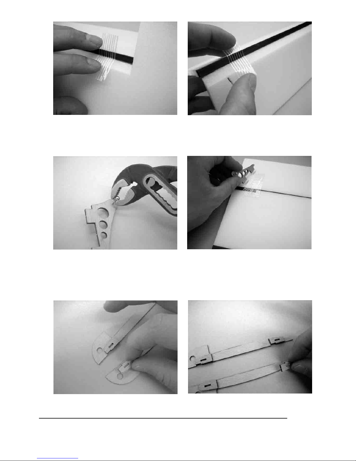
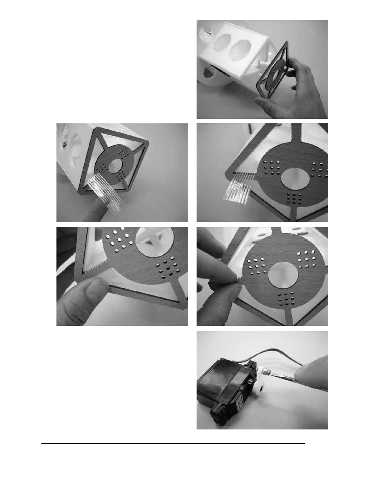
11. Nun die Querruder (26,27) 45° Fasen (darauf achten, dass rechte und linke Ruder gebaut werden
)und mit Glasfaserklebeband (28) an die Tragflächen ankleben. Auf der Gegenseite das erste und letzte
Scharnier kontern.
Page 9
9
GRAUPNER GmbH & Co. KG D-73230 KIRCHHEIM/TECK GERMANY
Keine Haftung für Druckfehler. Technische Änderungen vorbehalten! 04/2007
ID# 0057887
12. In die Querruder- Ruderhörner (29) die Kugelbolzen (30) eindrehen und das Ruderhorn in die
Aussparung der unteren Querruder einkleben. Die Kugelbolzen müssen nach außen zeigen.
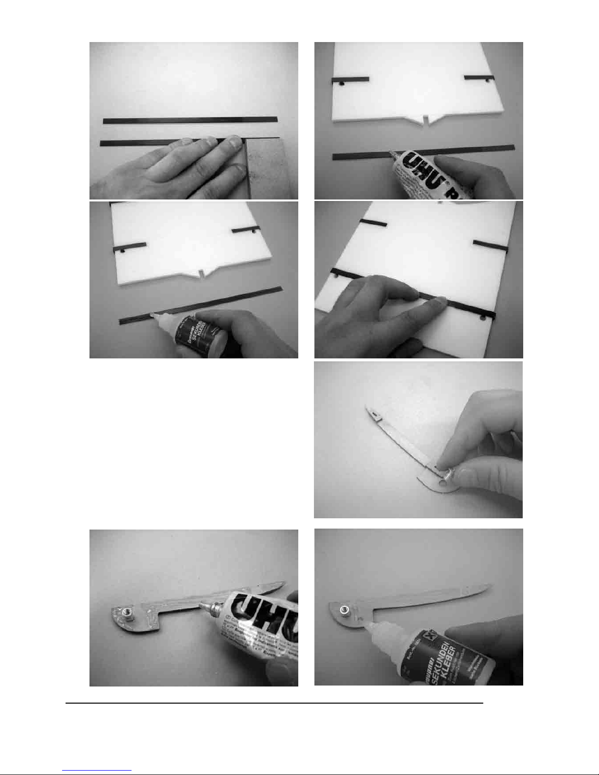
13. Mit dickflüssigem Sekundenkleber die Strebenaufnahmen vorn (31) und Strebenaufnahmen hinten (32)
mit der Mittelflügelaufnahme (33) verkleben. Darauf achten, dass ein linkes und ein rechtes Teil
entsteht.
Page 10
10
GRAUPNER GmbH & Co. KG D-73230 KIRCHHEIM/TECK GERMANY
Keine Haftung für Druckfehler. Technische Änderungen vorbehalten! 04/2007
ID# 0057887
14. Schleifen Sie die Mittelflügelverstärkung auf einer Seite rechts und links an und verkleben diese wie
beim Bauschritt 9+10 mit dem Tragflächenmittelstück (24,25)
15. Stecken Sie den Gewindebuchse (34) in die
Mittelflügelaufnahme (33) und verkleben diese mit
dem oberen Tragflächenmittelstück (24). Der
Gewindebuchse wird hier nur zum Ausrichten
der Aufnahmen benötigt, er wird erst später
eingeklebt
Page 11

11
GRAUPNER GmbH & Co. KG D-73230 KIRCHHEIM/TECK GERMANY
Keine Haftung für Druckfehler. Technische Änderungen vorbehalten! 04/2007
ID# 0057887
16. Die Verspannungsaufnahme (35) nach dem
gleichen System aufkleben. Dann die
Steckungsrohre etc. mit den
Tragflächenmittelstücken bündig verschleifen.
Page 12
12
GRAUPNER GmbH & Co. KG D-73230 KIRCHHEIM/TECK GERMANY
Keine Haftung für Druckfehler. Technische Änderungen vorbehalten! 04/2007
ID# 0057887
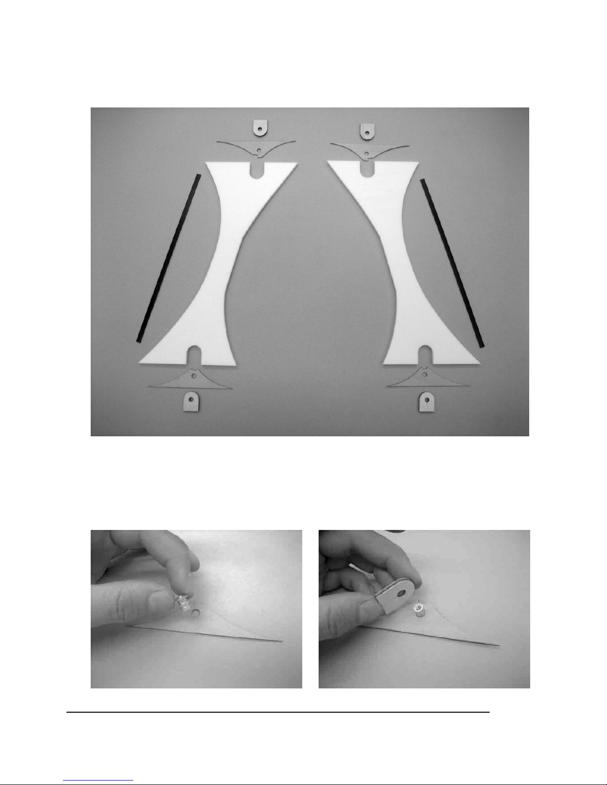
17. Um Fehler bei der Montage der Einzelteile zu vermeiden (für rechte und linke Strebe)sollten Sie alle
Teile für den Strebenbau wie auf dem Bild vor sich hinlegen:
Strebenverstärkung (15), Strebenseitenhalterung oben (36), Strebenseitenhalterung unten (37),
Strebenführung (38) und Streben (39).
18. Gewindebuchse in die Strebenseitenhalterung(36,37) einschieben, über Gewindebuchsee(34) die
Strebenführung(38) mit dickflüssigem- Sekundenkleber auf die Strebenseitenhalterung (36,37) kleben.
Darauf achten, dass an die Gewindebuchsee kein Klebstoff kommt, diese wird nur zum
Ausrichten benötigt und sollte nach dem Verkleben herausnehmbar sein. Dann die komplette
Halterung mit UHU-por bündig zur Ober- oder Unterkante der Strebe (39) verkleben.
Page 13
13
GRAUPNER GmbH & Co. KG D-73230 KIRCHHEIM/TECK GERMANY
Keine Haftung für Druckfehler. Technische Änderungen vorbehalten! 04/2007
ID# 0057887
19. Nun die Strebenverstärkung (15) mit UHU-por auf die Strebe (39) und mit Sekundenkleber in die
Halterung einkleben.
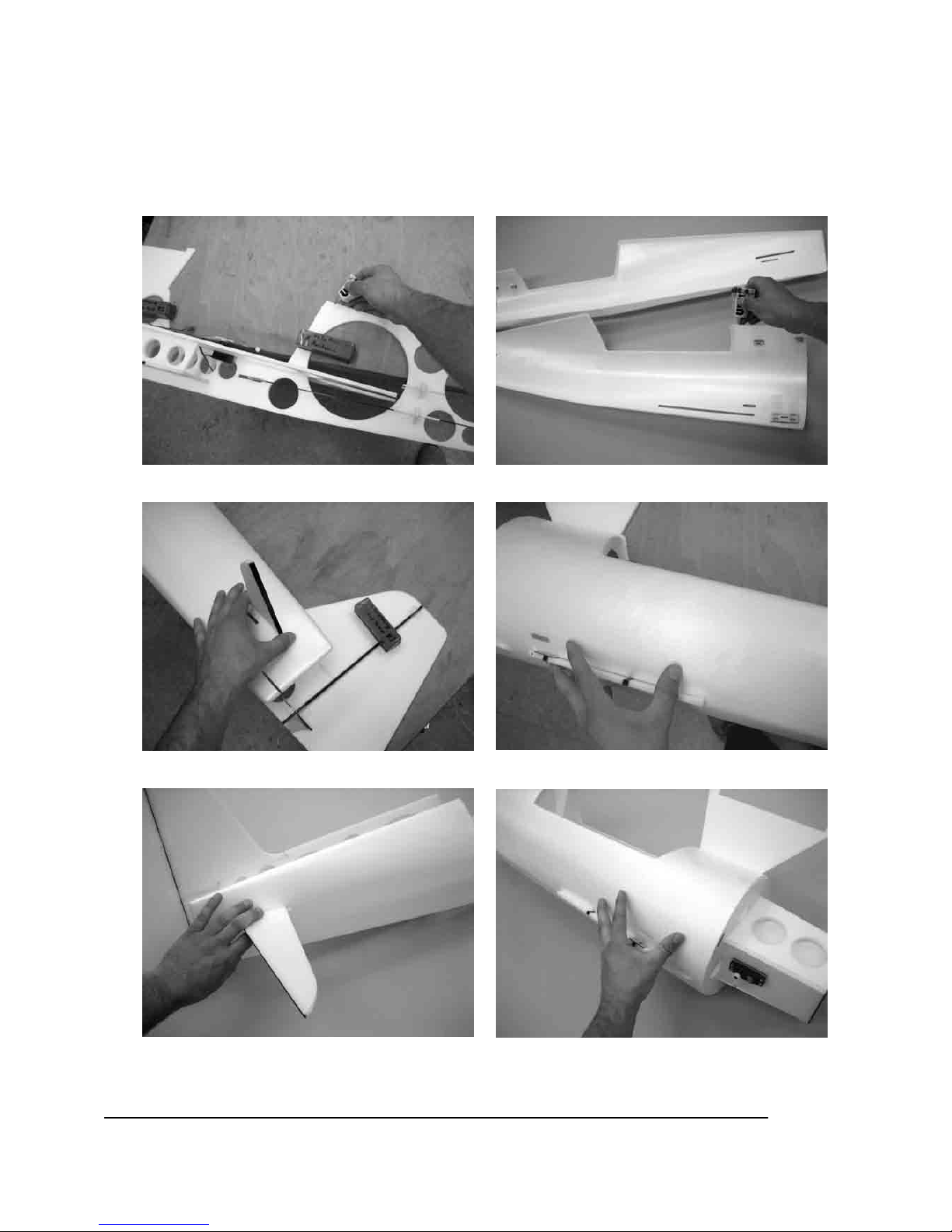
20. Mit UHU-por das Seitenleitwerk (40) an das
Rumpfmittelteil (41) kleben. Schleifen Sie an die
Endkante eine ca.15° Fase und kleben dort bündig
zur spitzen Kante mit UHU-por die
Seitenruderverstärkung (17) an
Page 14
14
GRAUPNER GmbH & Co. KG D-73230 KIRCHHEIM/TECK GERMANY
Keine Haftung für Druckfehler. Technische Änderungen vorbehalten! 04/2007
ID# 0057887
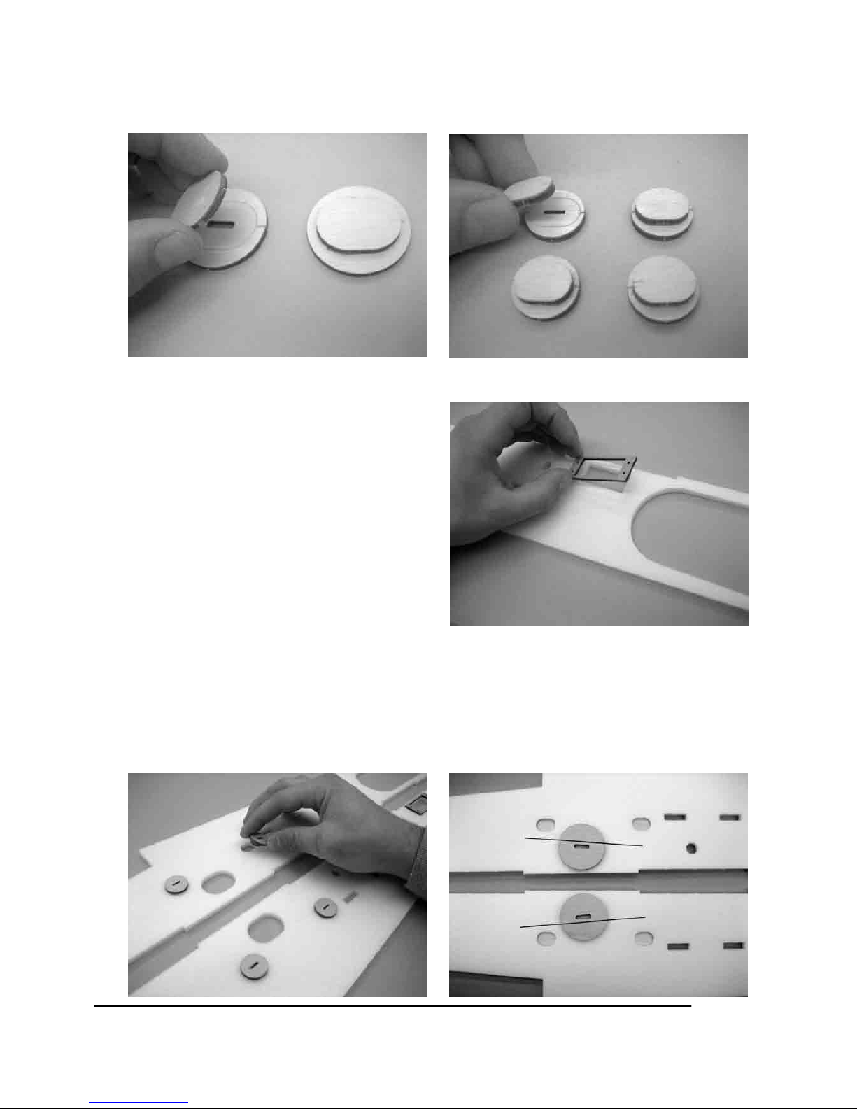
21. Mit dickflüssigem Sekundenkleber die großen Zentrierungsplättchen (42) auf die Fahrwerksaufnahme
(43) und die kleinen Zentrierungsplättchen (44) auf die Baldachinaufnahme (45) kleben. Darauf achten,
dass die Zentrierungsplättchen mit der Gravur genau übereinstimmen.
22. Bei den nächsten zwei Bauschritten sehr
genau auf die Bilder achten, damit die
Servohalterung und die Aufnahmen auf der
richtigen Seite der Längsspanten angeklebt
werden. Mit UHU-por auf den linken Längsspant
(45) eine der Servohalterungen(46 oder 47 bei 47
in der Aussparung vermitteln) über die Aussparung
kleben.
23. Die Baldachin- und Fahrwerksaufnahmen mit UHU-por in die Längsspanten (45,48) einkleben. Die
Fahrwerksaufnahmen zeigen vorne weiter auseinander.
Page 15
15
GRAUPNER GmbH & Co. KG D-73230 KIRCHHEIM/TECK GERMANY
Keine Haftung für Druckfehler. Technische Änderungen vorbehalten! 04/2007
ID# 0057887
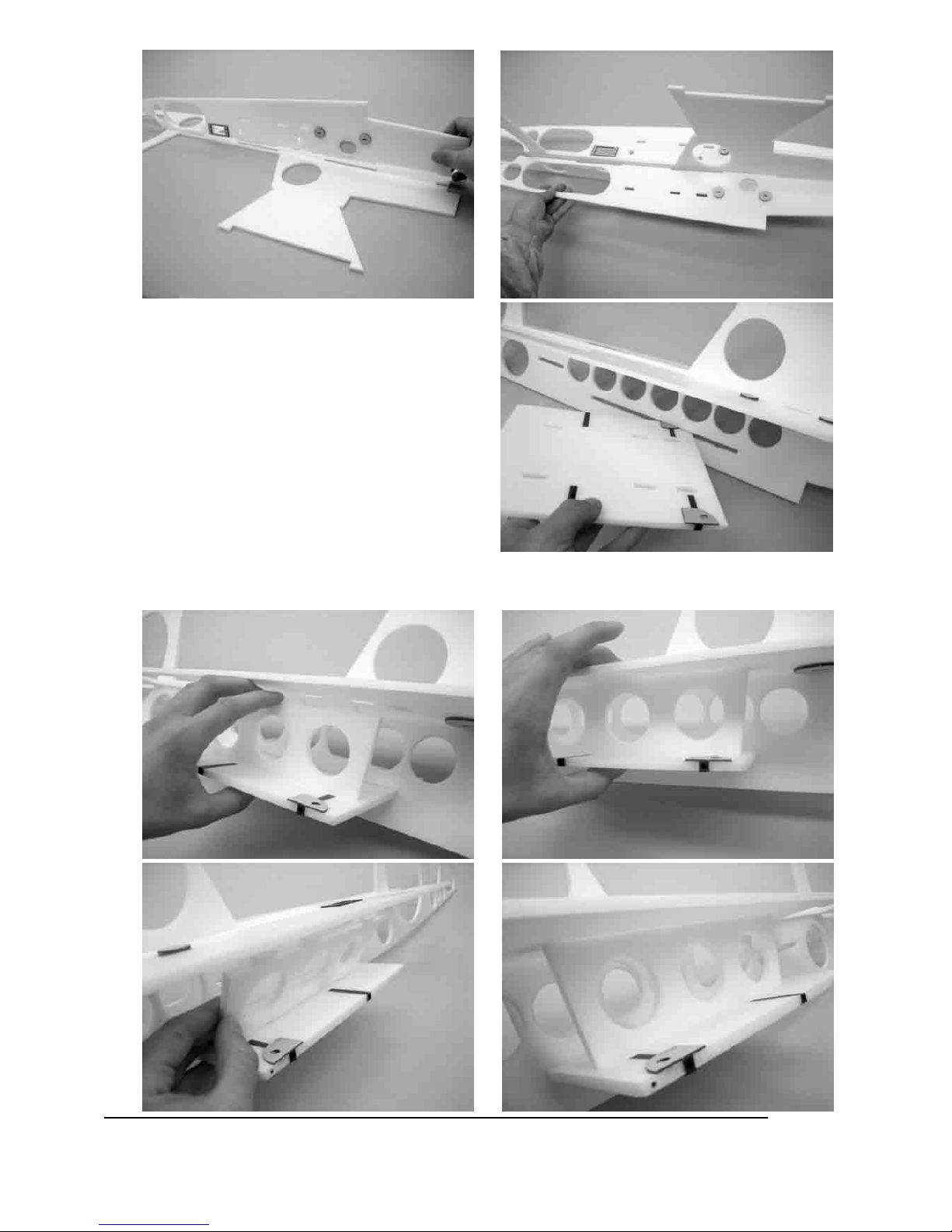
24. Mit UHU-por die Längsspanten (45,48) in das Rumpfmittelteil (41) einkleben.
25. Das untere Tragflächenmittelstück in das
Rumpfgerippe einschieben.
26. Die Verbindungsspanten (49) unter leichtem Druck in die Aussparungen einsetzen, dann das
Mittelstück von vorne her ausrichten, dass die Verbindungsspanten(49) im rechten Winkel zum
Mittelstück und zum Rumpf stehen.
Page 16
16
GRAUPNER GmbH & Co. KG D-73230 KIRCHHEIM/TECK GERMANY
Keine Haftung für Druckfehler. Technische Änderungen vorbehalten! 04/2007
ID# 0057887
27. Mit Styropor-Sekundenkleber die
Bowdenzugrohre(50) in die Gestängeführungen
(51,52) einkleben. Kleben Sie dann die
Seitenrudergestängeführung (52) in die untere
Aussparung auf die linke Seite des
Rumpfmittelteiles und die
Höhenrudergestängeführungen von beiden Seiten
in die darüber liegende Aussparung.
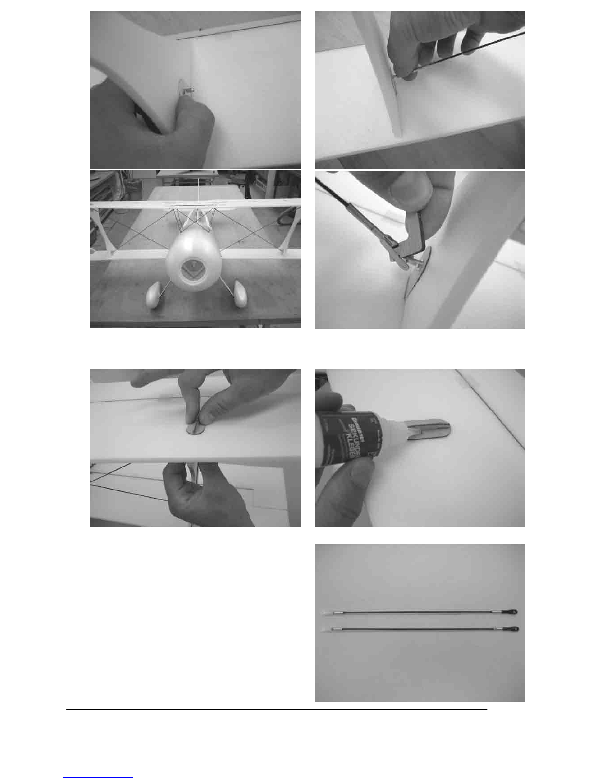
28. Schleifen Sie an die Endkante des Höhenleitwerkes (53) eine ca.15° Fase und kleben dort bündig zur
spitzen Kante mit UHU-por die Höhenruderverstärkung (18) an.
29. Kleben Sie nun das Höhenleitwerk (53) 90° zum
Rumpfmittelteil mit Styropor-Sekundenkleber ein.
Am Höhenleitwerk (53) sind vorn und hinten in der
Mitte des Leitwerks 6mm breite Halbkreise
ausgelasert die das Ausrichten erleichtern.
Page 17
17
GRAUPNER GmbH & Co. KG D-73230 KIRCHHEIM/TECK GERMANY
Keine Haftung für Druckfehler. Technische Änderungen vorbehalten! 04/2007
ID# 0057887
30. Biegen Sie den Spornradbügel (54) ca. 91 °auf. Stecken Sie zur Kontrolle ein Ruderhorn (56) in das
Seitenruder (55), der Sporenradbügel sollte nun parallel zum Ruderhorn und der Aussparung verlaufen.
31. Kleben Sie mit dickflüssigem Sekundenkleber
zuerst die kurze Aufdickung (58) bündig zur
Längsseite in die untere linke Ecke der
Spornradbügelaufnahme (57). Dann den
Spornradbügel an die kurze Aufdickung (58)
anlegen und die lange Aufdickung (59) und den
Spornradbügel (54) verkleben. Um den Kasten zu
schließen die zweite Spornradbügelaufnahme (57)
aufkleben.
Page 18
18
GRAUPNER GmbH & Co. KG D-73230 KIRCHHEIM/TECK GERMANY
Keine Haftung für Druckfehler. Technische Änderungen vorbehalten! 04/2007
ID# 0057887
32. Schleifen Sie an das Seitenruder (55) eine 45° Fase und kleben dann mit Styropor-Sekundenkleber das
Ruderhorn ein.
33. Den Spornradbügel mit der Aufnahme in die Aussparung im Seitenruder und an das Ruderhorn (56)
kleben. Die Zusatzverstärkung (60) mit UHU-por und mit dickflüssigem Sekundenkleber ankleben.
34. Mit Glasfaserklebeband das Seitenruder an den Rumpf montieren und von der Gegenseite die beiden
äußeren Klebestreifen kontern.
Page 19
19
GRAUPNER GmbH & Co. KG D-73230 KIRCHHEIM/TECK GERMANY
Keine Haftung für Druckfehler. Technische Änderungen vorbehalten! 04/2007
ID# 0057887
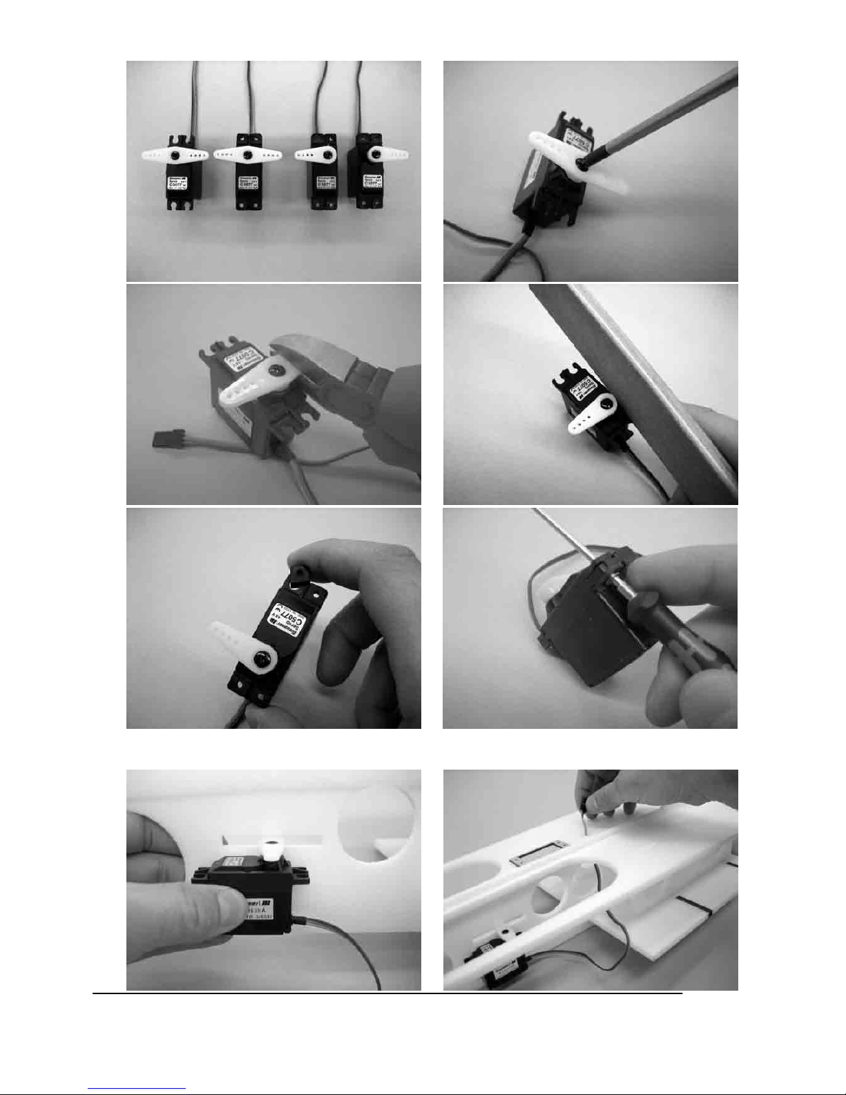
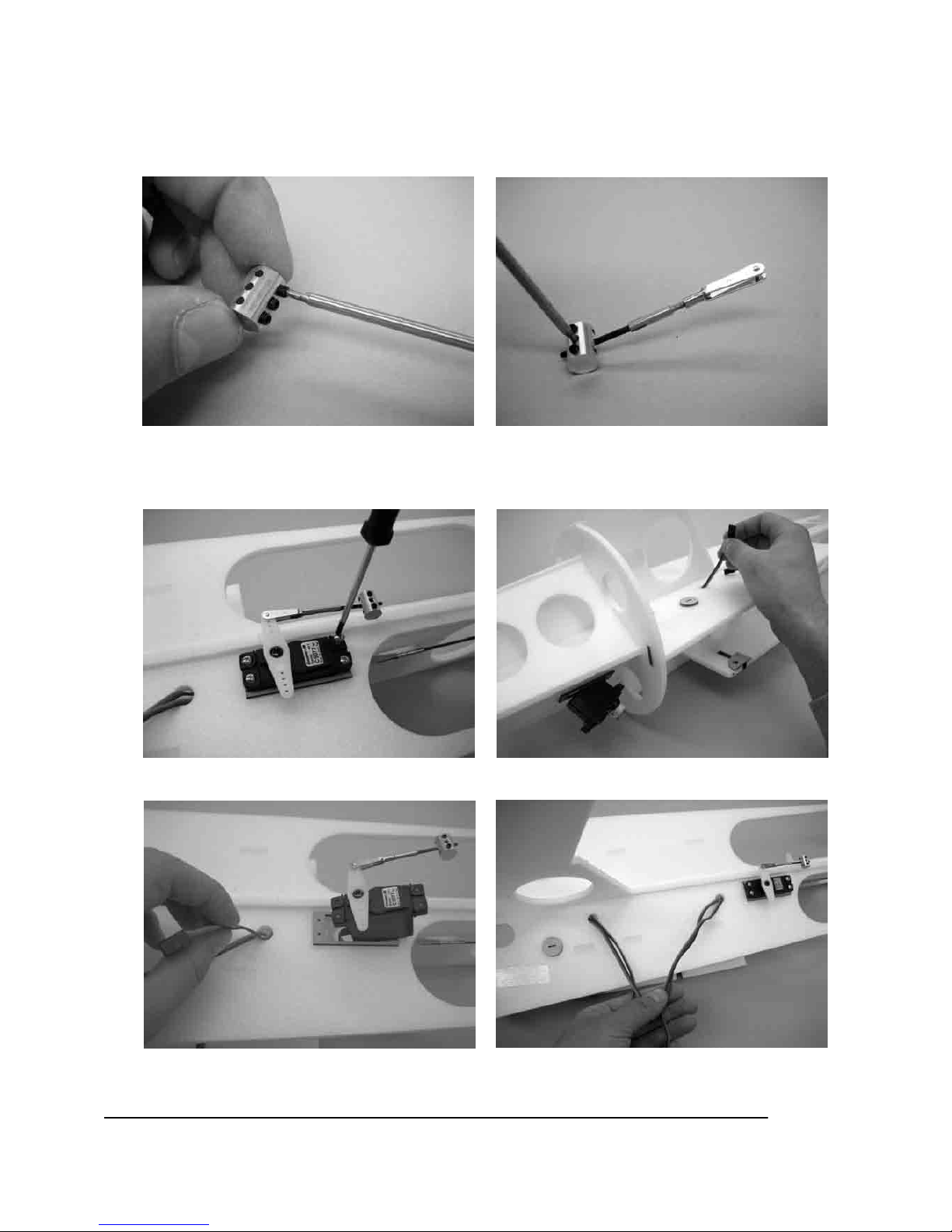
35. Montieren Sie die Hochlast- Servoarme (61) und die Servobefestigungen. Die Hochlast- Servoarme wie
auf den folgenden Bildern kürzen und verputzen.
36. Mit UHU-por das Seitenruderservo mittig zum Schlitz an den Rumpf kleben.
Page 20

20
GRAUPNER GmbH & Co. KG D-73230 KIRCHHEIM/TECK GERMANY
Keine Haftung für Druckfehler. Technische Änderungen vorbehalten! 04/2007
ID# 0057887
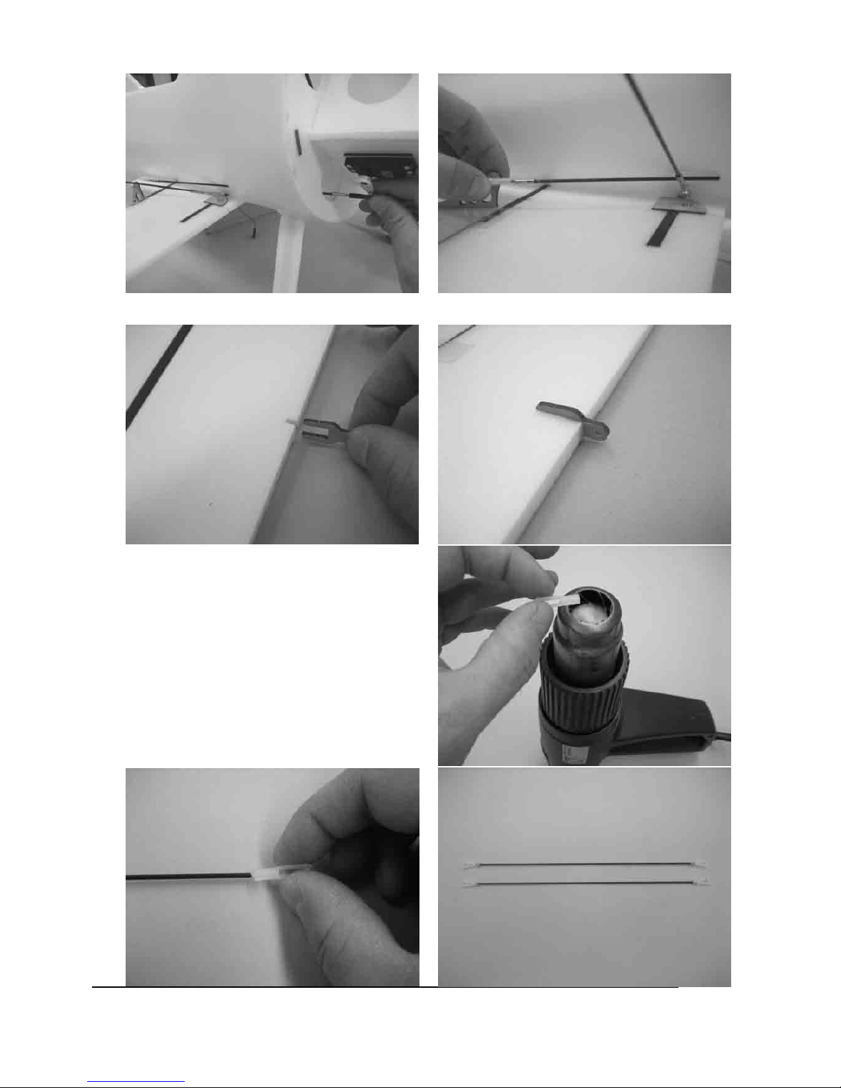
37. Mit dickflüssigem Sekundenkleber die Löthülse (62) auf das auf beiden Seiten angeraute
Seitenrudergestänge (3) aufkleben und den Gabelkopf (63) aufdrehen. Darauf achten, dass die
Löthülse bis zum Anschlag aufgeschoben wird. Dies gilt für alle Bauschritte die diesem gleichen
oder ähneln.
38. Seitenrudergestänge (3) einführen in der Löthülse verkleben und die Gabelköpfe in den Servoarm, bzw.
in das Ruderhorn einhängen.
Page 21
21
GRAUPNER GmbH & Co. KG D-73230 KIRCHHEIM/TECK GERMANY
Keine Haftung für Druckfehler. Technische Änderungen vorbehalten! 04/2007
ID# 0057887
39. Wichtig: Kleben Sie in einem Abstand von ca. 15mm parallel zur Außenkante des Motordomes auf
jede Seite einen ca. 240mm langes Glasfaserklebeband (28).
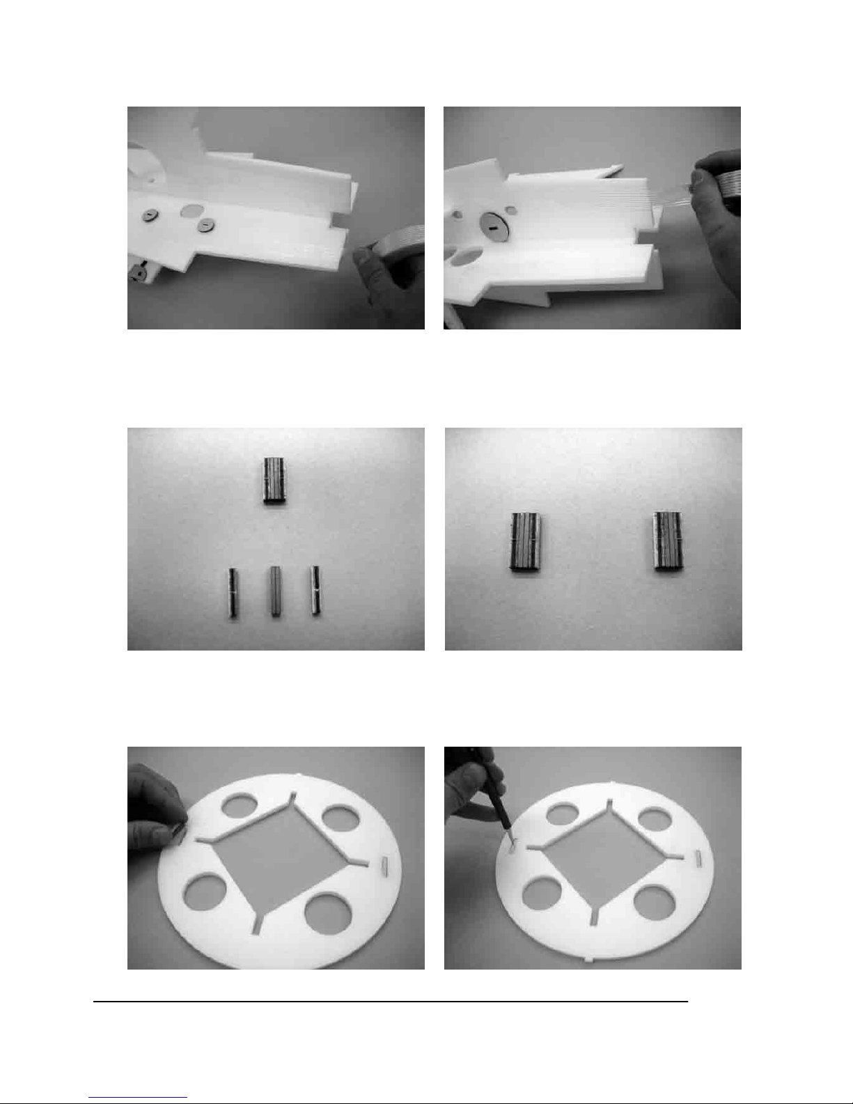
40. Mit dickflüssigem Sekundenkleber rechts und links auf zwei sich anziehende Magneten (64) die
Aufdickungen (65) bündig aufkleben. Sie benötigen dies zwei mal. Markieren Sie die
zueinandergehörigen Magnetpaare.
41. Trennen Sie die Magnetpaare von einander und kleben von jedem Paar eins mit StyroporSekundenkleber in die Aussparungen des vorderen Rumpfspantes (66), so dass diese mit der
Magnetseite bündig mit dem Rumpfspant (66) auf dem Baubrett aufliegen.
Page 22
22
GRAUPNER GmbH & Co. KG D-73230 KIRCHHEIM/TECK GERMANY
Keine Haftung für Druckfehler. Technische Änderungen vorbehalten! 04/2007
ID# 0057887
42. Schieben Sie den Rumpfspant von vorn auf das
Rumpfkreuz. Verkleben Sie die beiden Teile mit
Styropor-Sekundenkleber
43. Mit UHU-por die Servohalterung (46 oder47)auf die Motordomverstärkung (67) aufkleben und an die
Motordomverstärkungen (67 und 68) eine 45° Fase schleifen. Darauf achten, dass rechte und linke
Teile hergestellt werden.
44. Wie auf den Bildern die Motordomverstärkungen
mit UHU-por und mit Styropor-Sekundenkleber an
das Rumpfkreuz kleben.
Page 23
23
GRAUPNER GmbH & Co. KG D-73230 KIRCHHEIM/TECK GERMANY
Keine Haftung für Druckfehler. Technische Änderungen vorbehalten! 04/2007
ID# 0057887
45. Mit UHU-por den Motorspant an den Motordom
kleben und mit Glasfaserklebeband (28 ca. 50mm
lang) sichern.
46. Schrauben Sie nun die Kugel des Kugelgelenkes
(70) mit der Schraube (71) an den Servoarm.
Page 24
24
GRAUPNER GmbH & Co. KG D-73230 KIRCHHEIM/TECK GERMANY
Keine Haftung für Druckfehler. Technische Änderungen vorbehalten! 04/2007
ID# 0057887
47. Kleben Sie auf das vordere Höhenrudergestänge 2 (20) eine Löthülse (62). Drehen Sie einen
Gabelkopf (63) auf. Befestigen Sie dann den Duo- Gestängeanschluss (72) mit einem Gewindestift (73)
am Gestänge. Das Gestänge in den Servoarm des Höhenruderservos einhängen.
48. Schrauben Sie die Querruder- und das Höhenruder- Servo mit den dem Servo beiliegenden Schrauben
in das Rumpfkreuz ein. Verlegen Sie die Kabel der Servos wie auf den Bildern.
Page 25
25
GRAUPNER GmbH & Co. KG D-73230 KIRCHHEIM/TECK GERMANY
Keine Haftung für Druckfehler. Technische Änderungen vorbehalten! 04/2007
ID# 0057887
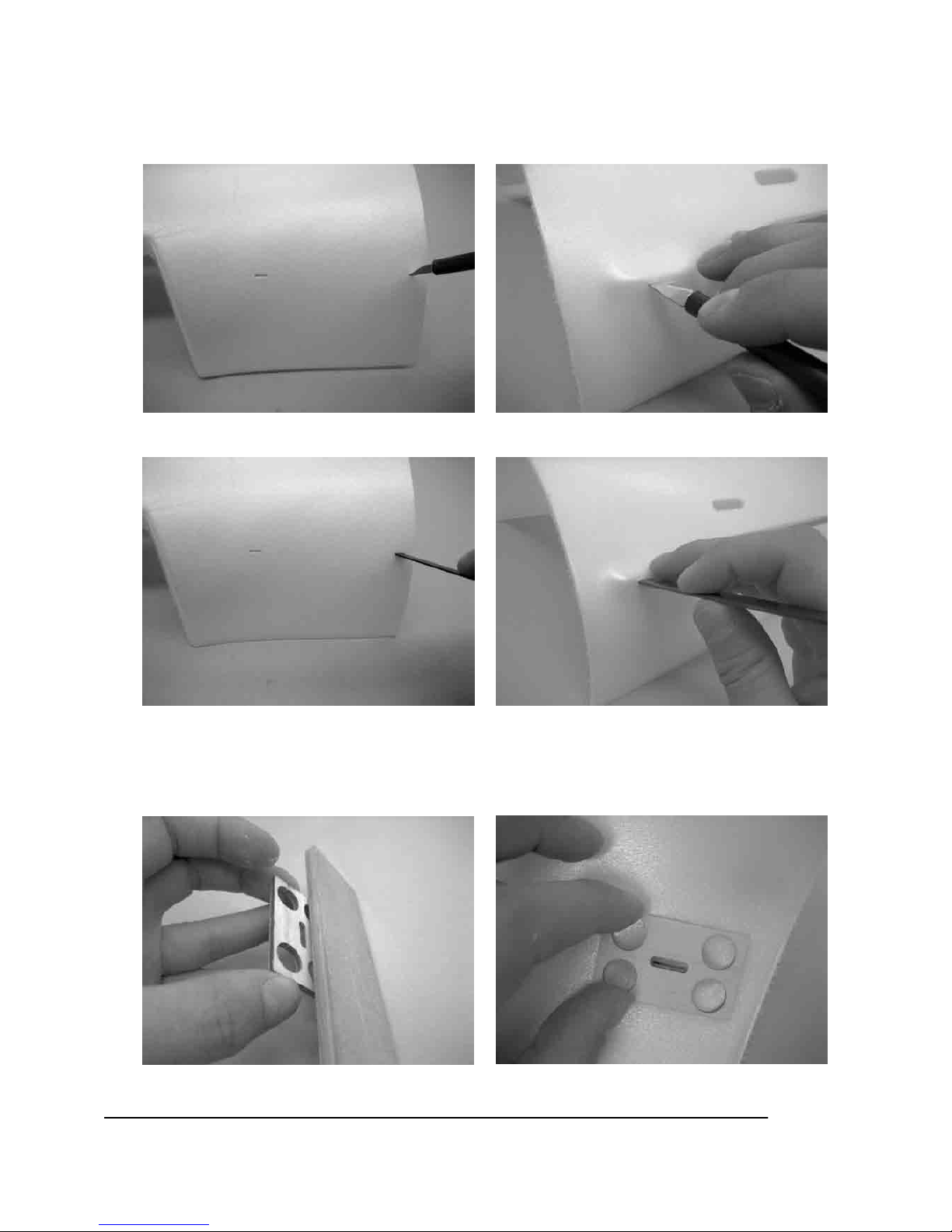
49. Die linke- und rechte Rumpfhälfte (74 und 75) mit einem Messer an den Markierungen für
Baldachinstreben und Fahrwerksbeine durchstechen und mit den jeweiligen CFK- Stäben den Schlitz
aufweiten. Die Schlitze keinesfalls länger als die Markierung einschneiden.
50. Die Fahrwerksdurchführung (76) an die Rundung des Rumpfes anpassen und mit UHU-por ankleben.
Die Aussparung im Rumpf und in der Fahrwerksdurchführung sollten bei der direkten Draufsicht
übereinstimmen.
Page 26
26
GRAUPNER GmbH & Co. KG D-73230 KIRCHHEIM/TECK GERMANY
Keine Haftung für Druckfehler. Technische Änderungen vorbehalten! 04/2007
ID# 0057887
51. Mit UHU-por die vordere- und hintere
Baldachindurchführung (77,78) ankleben. Hierbei
auf die Maße achten!
52. Über die Durchführungen Glasfaserklebeband (28) zur Verstärkung kleben.
Page 27
27
GRAUPNER GmbH & Co. KG D-73230 KIRCHHEIM/TECK GERMANY
Keine Haftung für Druckfehler. Technische Änderungen vorbehalten! 04/2007
ID# 0057887
53. Vor dem nächsten Bauschritt sollten Sie die Rumpfhälften probehalber Aufschieben um zu sehen in
welche Richtung Sie die Halbschalen drücken müssen. Legen Sie das Rumpfkreuz auf die Tischkante
und beschweren es. Nun nur auf die Rumpfsenkrechte und die Stoßkanten der Rumpfhalbschale UHUpor aufbringen und ca. 1 - 2min ablüften lassen. Direkt vor dem aufschieben der Rumpfhalbschale, auf
den Längsspant und den Rumpfspant UHU-por auftragen (Nass- Verklebung). Nun die Halbschale
aufschieben und andrücken. Verfahren Sie mit der zweiten Rumpfhälfte gleich. Dann das Höhenleitwerk
mit den Rumpfhalbschalen verkleben.
Page 28

28
GRAUPNER GmbH & Co. KG D-73230 KIRCHHEIM/TECK GERMANY
Keine Haftung für Druckfehler. Technische Änderungen vorbehalten! 04/2007
ID# 0057887
54. Schleifen Sie an die Höhenruder (79) eine 45° Fase. Kleben Sie mit Styropor-Sekundenkleber die
Ruderhörner (56) ein.
55. Einseitig auf das Höhenruder-Gestänge (1) Löthülse und Gabelkopf anbringen. Die fertigen Gestänge in
die Ruderhörner einhängen und Glasfaserklebeband (28) aufkleben.
56. Führen Sie das Höhenrudergestänge in den Rumpf durch die Bowdenzugrohre in den DuoGestängeanschluss ein. Montieren Sie die Höhenruder an der Höhenruderdämpfungsfläche. Stellen Sie
die Ruder auf Neutral. Klemmen Sie die Gestänge im Duo Gestängeanschluss fest.
Page 29

29
GRAUPNER GmbH & Co. KG D-73230 KIRCHHEIM/TECK GERMANY
Keine Haftung für Druckfehler. Technische Änderungen vorbehalten! 04/2007
ID# 0057887
57. Schleifen Sie die Fahrwerksverstärkung (6) ganzflächig und das Fahrwerksbein (5) auf der Länge der
Fahrwerksverstärkung (6) an. Mit dickflüssigem Sekundenkleber die beiden Teile bündig zu einander
verkleben.
58. Bohren Sie mittig ein 4mm Loch 15mm von der Unterkannte des Fahrwerkbeines. Ziehen Sie den
Bohrer nach unten um ein schräges Loch zu bekommen. Der Winkel sollte ca. 60° betragen.
Page 30

30
GRAUPNER GmbH & Co. KG D-73230 KIRCHHEIM/TECK GERMANY
Keine Haftung für Druckfehler. Technische Änderungen vorbehalten! 04/2007
ID# 0057887
59. Stecken Sie die Fahrwerksbeine in den Rumpf
(noch nicht verkleben), führen Sie die
Radachsen (9) in die Bohrung ein. Legen Sie ein
Stahllineal vom rechten zum linken
Fahrwerksbein, heften Sie nun mit dünnflüssigem
Sekundenkleber die Radachsen parallel zum
Baubrett und mit etwas Vorspur in die
Fahrwerksbeine. Zur Kontrolle des richtigen
Winkels legen Sie die Fahrwerksbeine
nebeneinander, die Radachsen sollten dann oben
ca. 2mm auseinander stehen. Mit 5 min Epoxy die
Radachse verkleben.
60. Mit UHU-por die Radachsenführung (80) deckend
zu der Bohrung in den Radverkleidungshälften (81
und 82) kleben. Radverkleidungshälften (83 und
84) mit Radverkleidungshälften (81 und 82)
verkleben
Page 31

31
GRAUPNER GmbH & Co. KG D-73230 KIRCHHEIM/TECK GERMANY
Keine Haftung für Druckfehler. Technische Änderungen vorbehalten! 04/2007
ID# 0057887
61. Schieben Sie zwei Führungsringe (84) auf die Radachse, führen Sie das Rad in die Radverkleidung ein,
nun die Radverkleidung und das Rad aufschieben, zur Sicherung wieder zwei Führungsringe (84)
aufschieben.
62. Gewindestift (73) in Stellring (85) zwei
Gewindegänge eindrehen. Messing- Rohrniet (86)
in Spornrad (87) einschieben, Stellring
aufschieben und an Spornradbügel montieren.
Page 32

32
GRAUPNER GmbH & Co. KG D-73230 KIRCHHEIM/TECK GERMANY
Keine Haftung für Druckfehler. Technische Änderungen vorbehalten! 04/2007
ID# 0057887
63. Fahrwerk in den Rumpf schieben, Radverkleidungen ausrichten und mit Styropor-Sekundenkleber
heften. Das Fahrwerk aus dem Rumpf entnehmen und mit dünnflüssigem Sekundenkleber den
Führungsring (84) mit der Radachsenführung und der Radachse verkleben. Nun das Rad in der
Radverkleidung ausrichten und mit den Führungsringen auf der Position mit dünnflüssigem
Sekundenkleber sichern. Darauf achten, dass kein Sekundenkleber in die Radnabe gelangt.
Überstand der Radachse bündig mit der Radverkleidung verschleifen.
Page 33

33
GRAUPNER GmbH & Co. KG D-73230 KIRCHHEIM/TECK GERMANY
Keine Haftung für Druckfehler. Technische Änderungen vorbehalten! 04/2007
ID# 0057887
64. Mit UHU-por die Fahrwerksattrappen (88) auf das
Fahrwerk mittig und bündig zur Radverkleidung
kleben. Das Fahrwerk in den Rumpf stecken und
solange kürzen, bis die Fahrwerksattrappe am
Rumpf anliegt. Fahrwerk noch nicht in den
Rumpf einkleben.
Page 34

34
GRAUPNER GmbH & Co. KG D-73230 KIRCHHEIM/TECK GERMANY
Keine Haftung für Druckfehler. Technische Änderungen vorbehalten! 04/2007
ID# 0057887
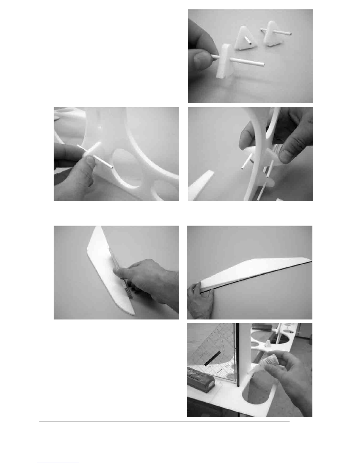
65. Rauen Sie die Baldachinstreben (12 und 13) auf
beiden Seiten 3mm breit an. Schieben Sie diese
dann in den Rumpf ein. Montieren Sie das obere
Tragflächenmittelstück auf der
Baldachinschablone und stecken Sie die
Baldachinstreben in die vorgesehenen
Aussparungen.
66. Mit Dickflüssigem- Sekundenkleber die Baldachinstreben einkleben.
Page 35

35
GRAUPNER GmbH & Co. KG D-73230 KIRCHHEIM/TECK GERMANY
Keine Haftung für Druckfehler. Technische Änderungen vorbehalten! 04/2007
ID# 0057887
67. Die Montagehilfen vorsichtig wegbrechen.
68. Die Baldachinverstrebung (19) und die
Baldachinstreben anrauen. Vor dem Einkleben
der Baldachinstreben die Passung überprüfen,
die Streben sollten ohne Druck passen. Nun
mit Styropor-Sekundenkleber und mit
dickflüssigem Sekundenkleber (oder 5min epoxy)
die Streben ankleben.
Page 36

36
GRAUPNER GmbH & Co. KG D-73230 KIRCHHEIM/TECK GERMANY
Keine Haftung für Druckfehler. Technische Änderungen vorbehalten! 04/2007
ID# 0057887
69. Nun das Fahrwerk anschleifen und einkleben.
Page 37

37
GRAUPNER GmbH & Co. KG D-73230 KIRCHHEIM/TECK GERMANY
Keine Haftung für Druckfehler. Technische Änderungen vorbehalten! 04/2007
ID# 0057887
70. Nun die restlichen Magneten von Bauschritt 41 an den Rumpfspant anbringen, den Motorhaubenspant
(89) aufschieben und die Magnete mit dem Motorhaubenspant verkleben. Darauf achten das der
Motorhaubenspant sauber anliegt. Den Motorhaubenspant wieder vom Rumpf trennen hierzu
verwenden Sie am besten ein Stahllineal.
71. Den Motorhaubespant auf das Baubrett legen mit der Magnetseite nach unten. Nun die
Motorhaubenlängsspanten (90) in die Aussparungen einschieben und mit Styropor-Sekundenkleber
einkleben. Den Motorhaubenverstärkungsspant (91) aufschieben und mit Styropor-Sekundenkleber
verkleben
Page 38

38
GRAUPNER GmbH & Co. KG D-73230 KIRCHHEIM/TECK GERMANY
Keine Haftung für Druckfehler. Technische Änderungen vorbehalten! 04/2007
ID# 0057887
72. Mit UHU-por Motorhaubenhalbschalen (92) bündig zum Motorhaubenspant (90) aufkleben. Sollte nach
Aufschieben der Motorhaube eine leichte Kante zwischen Rumpf und Haube sein, so können Sie die
Motorhaube mit leichtem Druck und Reiben dem Rumpf anpassen, dies ist fertigungstechnisch nicht
anders möglich.
73. Trennen Sie die Ölkühlerhalbschalen (93 und 94) mit etwas Übermaß an der Schneidelinie ab. Mit
UHU-por die Halbschalen zusammenkleben und an der Vorderseite eine Öffnung freischneiden.
Page 39

39
GRAUPNER GmbH & Co. KG D-73230 KIRCHHEIM/TECK GERMANY
Keine Haftung für Druckfehler. Technische Änderungen vorbehalten! 04/2007
ID# 0057887
74. Legen Sie einen ausreichend breiten und langen Streifen Schleifpapier (100er Körnung) auf die
Motorhaube. Schleifen Sie den Ölkühler passend ein und kleben ihn mit UHU-por ca. 15mm von der
hinterkante Motorhaube mittig auf.
75. Drehen Sie in den Gewindebuchse (34) die
Augenschraube (95) ein. Bei vier der
Gewindebuchseen bis zum Anschlag und beim
Rest lassen Sie einen Gewindegang frei. Kürzen
Sie das überstehende Gewinde.
76. Kleben Sie mit 5min Epoxy die Verspannungshalterung in das obere und das untere
Tragflächenmittelstück ein, so dass sich die Augenschrauben noch drehen lassen.
Page 40

40
GRAUPNER GmbH & Co. KG D-73230 KIRCHHEIM/TECK GERMANY
Keine Haftung für Druckfehler. Technische Änderungen vorbehalten! 04/2007
ID# 0057887
77. Fertigen Sie die Tragflächenverspannung (10 und 11) an und hängen diese in die Halterungen ein. Die
Verspannung (10) wird am Baldachin eingehängt und die Verspannung (11) an der unteren Tragfläche.
78. Kleben Sie mit UHU-por die Halterungsführung (95) deckend zur Aussparung in den Flügeln auf. Auf
den oberen Flügeln oben und auf den unteren Flügeln unten. Schieben Sie dann die Strebenhalterung
(96) durch die Führung und den Flügel hindurch.
79. Stecken Sie die Flächensteckungen (8) in die
Tragflächen und montieren diese am Rumpf.
Stecken Sie die Streben auf die Strebenhalterung
und schieben die Verspannungshalterung durch
die Strebe und die Strebenhalterung. Dann die
Verspannung in die Halterung einhängen. Dies an
allen Flügeln wiederhohlen. Durch Verdrehen der
Gabelköpfe an der Verspannung die Tragflächen
ausrichten. Die Gabelköpfe können nach dem
Ausrichten mit dünnflüssigem Sekundenkleber
gesichert werden. Mit dem Gabelkopföffner (97)
können die Gabelköpfe schnell und einfach
geöffnet und ausgehängt werden.
Page 41

41
GRAUPNER GmbH & Co. KG D-73230 KIRCHHEIM/TECK GERMANY
Keine Haftung für Druckfehler. Technische Änderungen vorbehalten! 04/2007
ID# 0057887
Page 42
42
GRAUPNER GmbH & Co. KG D-73230 KIRCHHEIM/TECK GERMANY
Keine Haftung für Druckfehler. Technische Änderungen vorbehalten! 04/2007
ID# 0057887
80. Die Strebenhalterungen an die Durchführungen andrücken und mit dickflüssigem Sekundenkleber
verkleben. Darauf achten das die Halterungen den gleichen Winkel wie die Streben haben.
81. Löthülsen (62) auf das Querrudergestänge (4)
aufkleben. Drehen Sie auf der einen Seite den
Kugelgelenkträger schwarz (98) und auf der
anderen Seite den Kugelgelenkträger natur (99)
auf.
Page 43
43
GRAUPNER GmbH & Co. KG D-73230 KIRCHHEIM/TECK GERMANY
Keine Haftung für Druckfehler. Technische Änderungen vorbehalten! 04/2007
ID# 0057887
82. Drücken Sie die Kugelgelenkträger auf die Kugeln. Stellen Sie die Servos in die Neutralstellung und
justieren die Gestängelänge durch Ein- oder Ausdrehen der Kugelgelenkträger, so dass die Querruder
auf neutral stehen.
83. Mit Styropor-Sekundenkleber die Verbindungsruderhörner (100) in die Aussparungen der Querruder
einkleben.
84. Fertigen Sie Querruderverbindungsgestänge
(2)an. Mit einem Heißluftföhn den
Kunststoffgabelkopf (101) erwärmen und auf den
CFK- Stab aufschieben.
Page 44

44
GRAUPNER GmbH & Co. KG D-73230 KIRCHHEIM/TECK GERMANY
Keine Haftung für Druckfehler. Technische Änderungen vorbehalten! 04/2007
ID# 0057887
85. Das Gestänge in die Ruderhörner einhängen und wenn nötig nachjustieren.
86. Stecken Sie die dem Motor beiliegenden Schrauben in die Bohrungen der Motorhalterung (102) und
verkleben die beiden Teile mit dickflüssigem Sekundenkleber. Darauf achten, dass kein Klebstoff an
die Schrauben gelangt.
87. Montieren Sie den Motor, achten Sie auf die
Befestigungsrichtung wie auf dem Bild rechts.
88. Die Befestigungsschrauben (103) in die Halterung
einschieben.
Page 45

45
GRAUPNER GmbH & Co. KG D-73230 KIRCHHEIM/TECK GERMANY
Keine Haftung für Druckfehler. Technische Änderungen vorbehalten! 04/2007
ID# 0057887
89. Die Gummitüllen (104) aufstecken und die Antriebseinheit am Motorträger montieren.
90. Mit dünnflüssigem Sekundenkleber in die Spinnerhalteplatten (105) die Magneten (64) bündig zur
Spinnerhalteplattefläche einkleben. Dabei auf die Anziehungsrichtung der Magnete achten, dass
rechte und linke Teile entstehen und der Spinner in beide Richtungen montiert werden kann.
91. Die Magneten in die Spinnergrundplatte (106) bündig zur Fläche einkleben und die Spinnerhalteplatten
deckend darauf ausrichten.
Page 46
46
GRAUPNER GmbH & Co. KG D-73230 KIRCHHEIM/TECK GERMANY
Keine Haftung für Druckfehler. Technische Änderungen vorbehalten! 04/2007
ID# 0057887
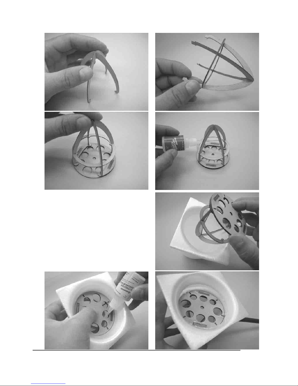
92. Die Spinnerführungsspanten (107,108 und 109 ) zusammenschieben. In die Halterplatten und die
Grundplatte einführen und mit dünnflüssigem Sekundenkleber heften . Darauf achten das kein
Klebstoff zwischen die Platten gerät. Danach die Spinnergrundplatte (106) vom Spinnergerüst
trennen und mit dickflüssigem Sekundenkleber nachkleben.
93. Das Spinnergerüst in die Spinnerkappe (110)
einschieben und unter leichtem Druck mit
Styropor-Sekundenkleber heften. Dann das
überstehende Spinnermaterial mit einem leichten
Überstand abtrennen und bündig mit der
Spinnergrundplatte verschleifen. Die
Spinnergrundplatte entfernen und das
Spinnergerüst nachkleben.
Page 47

47
GRAUPNER GmbH & Co. KG D-73230 KIRCHHEIM/TECK GERMANY
Keine Haftung für Druckfehler. Technische Änderungen vorbehalten! 04/2007
ID# 0057887
94. Montieren Sie die Luftschraubenaufnahme (111) am Motor. Schieben Sie dann die Spinnergrundplatte
und das Luftschrauben Zwischenstück (112) auf. Die Luftschrauben am Luftschraubenmittelstück (113)
montieren. Die Blatthalterschrauben mit Schraubensicherungslack sichern. Wie auf den Bildern,
die Luftschrauben Einheit an der Spinnergrundplatte ausrichten und montieren.
Page 48

48
GRAUPNER GmbH & Co. KG D-73230 KIRCHHEIM/TECK GERMANY
Keine Haftung für Druckfehler. Technische Änderungen vorbehalten! 04/2007
ID# 0057887
95. Das Akku- Reglerkabel um ca. 80mm verlängern und den Regler an den Motor anschließen (gelb zu
gelb, rot zu schwarz und blau zu rot). Den Regler mit Klettband oder mit UHU-por befestigen. Dann
Regler und Servos am Empfänger anschließen. Ebenfalls mit Klettband oder mit UHU-por befestigen.
Antennenkabel im Rumpf verlegen.
96. Kleben Sie eine Seite des Haken- und
Schlaufenbandes (114) in den Rumpf. Die andere
Seite auf den Akku.
97. Klappen Sie die Luftschraubenplätter nach vorne.
Schieben Sie dann die Motorhaube auf den
Rumpf auf. Nun aus der Spinnerkappe die
Aussparungen für die Luftschraube ausschneiden
und den Spinner auf der Grundplatte montieren.
Page 49

49
GRAUPNER GmbH & Co. KG D-73230 KIRCHHEIM/TECK GERMANY
Keine Haftung für Druckfehler. Technische Änderungen vorbehalten! 04/2007
ID# 0057887
98. Legen Sie den Haubenrahmen (115) mit der
Unterseite auf ihr Baubrett. Die Unterseite ist die
Seite mit der Gravur. Dann die Magneten bündig
zur Unterseite mit Styropor-Sekundenkleber
einkleben.
99. Kleben mit Styropor-Sekundenkleber Sie die Armaturenbrettverstärkung (116) in das Armaturenbrett
(117). Das Armaturenbrett dann mit Styropor-Sekundenkleber in die Aussparungen im Haubenrahmen
einkleben.
100. Mit Styropor-Sekundenkleber die Magnete in den Rumpf einkleben. Darauf achten, dass sich die
Magnete zum Haubenrahmen anziehen und nicht abstoßen.
Page 50

50
GRAUPNER GmbH & Co. KG D-73230 KIRCHHEIM/TECK GERMANY
Keine Haftung für Druckfehler. Technische Änderungen vorbehalten! 04/2007
ID# 0057887
101. Biegen Sie den Haubenrahmen an der Gravur nach oben. Geben Sie in den hier entstandenen Spalt
hinten und vorn etwas Styropor-Sekundenkleber. Styropor-Sekundenkleber nur bis ca. 25mm ans
Ende des Spaltes. Den Haubenrahmen auf den Rumpf setzen und Styropor-Sekundenkleber
aushärten lassen.
102. Mit Glasfaserklebeband den Knick verstärken.
103. Wenn Sie möchten können Sie den
Haubenrahmen Lackieren. Dies sollten Sie dann
jetzt tun, da es zu einem späteren Zeitpunk
schwer oder nicht mehr möglich ist.
104. Auf den Haubenrahmen und die Pilotenköpfe
(118) das Dekor aufkleben.
Page 51

51
GRAUPNER GmbH & Co. KG D-73230 KIRCHHEIM/TECK GERMANY
Keine Haftung für Druckfehler. Technische Änderungen vorbehalten! 04/2007
ID# 0057887
105. Mit Styropor-Sekundenkleber oder mit UHU-por
den Pilot in den Haubenrahmen einkleben.
106. Die Kabinenhaube (119) an der Schneidelinie
austrennen
107. Den Haubenrahmen auf den Rumpf setzen und der Rundung des Rumpfes anpassen. Ab und zu die
Passgenauigkeit der Kabinenhaube (119) kontrollieren.
108. Beim nächsten Bauschritt sollten Sie zu zweit
arbeiten, um eine unnötige Verschmutzung der
Haube mit UHU-por zu vermeiden. Markieren
Sie die Position der Haube auf dem Rumpf,
hierzu kann die Trennnaht des Rumpfes und der
Haubenrahmen als Positionierungshilfe
genommen werden. Tragen Sie auf die Seiten
des Haubenrahmen UHU-por auf. Dann die
Haube aufsetzen, abnehmen und ablüften
lassen. Auf die Haubenrahmenspanten UHU-por
auftragen, Haube aufsetzen und UHU-por
aushärten lassen. Nach ca. 10- 15 min kann die
Kabinenhaube abgenommen werden.
Page 52

52
GRAUPNER GmbH & Co. KG D-73230 KIRCHHEIM/TECK GERMANY
Keine Haftung für Druckfehler. Technische Änderungen vorbehalten! 04/2007
ID# 0057887
109. Der Haubenrahmen kann entweder mit Styroporlack lackiert, oder mit den Dekorbogen beklebt
werden
Page 53

53
GRAUPNER GmbH & Co. KG D-73230 KIRCHHEIM/TECK GERMANY
Keine Haftung für Druckfehler. Technische Änderungen vorbehalten! 04/2007
ID# 0057887
Stückliste
Pos. Benennung Anzahl Material Abmessung, Stärke und Länge in mm
1 Höhenruder-Gestänge (1) 2 CFK-Stab Rund Ø 2mm x 575mm
2 Querruderverbindungs-Gestänge 2 CFK-Stab Rund Ø 2mm x 268mm Rest von Höhenruder-
Gestänge
3 Seitenruder-Gestänge 1 CFK-Stab Rund Ø 2mm x 590mm
4
Querruder –Gestänge
2
CFK-Stab Rund
Ø 2mm x 230mm Rest von Seitenruder –
Gestänge und das 2. von dem beiliegenden
330mm CFK-Stab
5 Fahrwerksbein 2 CFK-Stab Flach 12 x 2,0 x 335mm
6 Fahrwerksverstärkung 2 CFK-Stab Flach 12 x 2,0 x 80mm Rest von Fahrwerksbein
7 Flächensteckungsrohr
8 CFK-Stab Vierkant
innen Ø 4mm
6 x 6 x innen Ø 4 x 85mm
8 Flächensteckung 8 CFK-Stab Rund Ø 4 x 80mm
9 Radachse 2 CFK-Stab Rund Ø 4 x 70mm Rest von Flächensteckung
10 Tragflächenverspannung (1) 2 CFK-Stab Rund Ø 1,6 x 405mm
11 Tragflächenverspannung (2) 2 CFK-Stab Rund Ø 1,6 x 420mm
12 Baldachinstreben vorn 2 CFK-Stab Flach 6 x 1 x 205mm
13 Baldachinstreben hinten 2 CFK-Stab Flach 6 x 1 x 208mm
14 Tragflächenverstärkung 4 CFK-Stab Flach 6 x 1 x 2 Stäbe halbieren
15 Strebenverstärkung 2 CFK-Stab Flach 6 x 1 x 244mm
16 Mittelflügelverstärkung 2 CFK-Stab Flach 6 x 1 x 198mm Rest von Strebenverstärkung
17 Seitenruderverstärkung 1 CFK-Stab Flach 6 x 1 x 343mm
18 Höhenruderverstärkung 1 CFK-Stab Flach 6 x 1 x 634mm Rest von Seitenruderverstärkung
19 Baldachinverstrebung 2 CFK-Stab Flach 6 x 1 x 191mm aus Resten
20 Höhenrudergestänge (2) 1 CFK-Stab Rund Ø 2 x 30mm aus Resten
21 Verbindungskeile 4 Birke Laserteil 3mm
22 Obere Tragflächen 2 Depron® Laserteil, 6mm stark
23 Untere Tragflächen 2 Depron® Laserteil, 6mm stark
24 Oberes Tragflächenmittelstück 1 Depron® Laserteil, 6mm stark
25 Unteres Tragflächenmittelstück 1 Depron® Laserteil, 6mm stark
26 Obere Querruder 2 Depron® Laserteil, 6mm stark
27 Untere Querruder 2 Depron® Laserteil, 6mm stark
28 Glasfaserklebeband Best.- Nr.98709 Je nach Bedarf, nicht im Bausatz enthalten
29 Querruder- Ruderhorn 2 Buche Laserteil, 2mm stark
30 Kugelbolzen 2 Stahl Fertigteil mit 2mm Gewinde
31 Strebenaufnahme vorn 2 Buche Laserteil, 2mm stark
32 Strebenaufnahme hinten 2 Buche Laserteil, 2mm stark
33 Mittelflügelaufnahme 2 Buche Laserteil, 1mm stark
34 Gewindebuchse 8 Aluminium Drehteil
35 Verspannungsaufnahme 2 Buche Laserteil, 1mm stark
36 Strebenseitenhalterung oben 2 Buche Laserteil, 1mm stark
37 Strebenseitenhalterung unten 2 Buche Laserteil, 1mm stark
38 Strebenführung 4 Birke Laserteil, 3mm stark
39 Streben 2 Depron® Laserteil, 6mm stark
40 Seitenleitwerk 1 Depron® Laserteil, 6mm stark
41 Rumpfmittelteil 1 Depron® Laserteil, 6mm stark
42 Zentrierungsplättchen groß 2 Birke Laserteil, 3mm stark
43 Fahrwerksaufnahme 2 Birke Laserteil, 3mm stark
44 Zentrierungsplättchen klein 4 Birke Laserteil, 3mm stark
45 Baldachinaufnahme 4 Birke Laserteil, 3mm stark
45 Längsspant links 1 Depron® Laserteil, 6mm stark
46 Servohalterung C 5077 3 Buche Laserteil, 2mm stark
47 Servohalterung DS 3728 oder DS
3781
3 Buche
Laserteil, 2mm stark
48 Längsspant rechts 1 Depron® Laserteil, 6mm stark
Page 54

54
GRAUPNER GmbH & Co. KG D-73230 KIRCHHEIM/TECK GERMANY
Keine Haftung für Druckfehler. Technische Änderungen vorbehalten! 04/2007
ID# 0057887
49 Verbindungsspant 2 Depron® Laserteil, 6mm stark
50 Bowdenzugrohr 3 Hart- PVC 3,2 x 2,2mm 70mm lang
51 Gestängeführung Höhenruder 2 Depron® Laserteil, 6mm stark
52 Gestängeführung Seitenruder 1 Depron® Laserteil, 6mm stark
53 Höhenleitwerk 1 Depron® Laserteil, 6mm stark
54 Spornradbügel 1 Stahl Biegeteil 1,5mm
55 Seitenruder 1 Depron® Laserteil, 6mm stark
56 Ruderhorn 3 Buche Laserteil, 2mm stark
57 Spornradbügelaufnahme 2 Buche Laserteil, 2mm stark
58 Aufdickung kurz 1 Buche Laserteil, 1mm stark
59 Aufdickung lang 1 Buche Laserteil, 2mm stark
60 Zusatzverstärkung 1 Buche Laserteil, 1mm stark
61 Hochlast- Servoarme 4 Best.-Nr. 3544 Nicht im Bausatz enthalten
62 Löthülse 17 Stahl Drehteil
63 Gabelkopf 13 Stahl Biegeteil
64 Magnet 12 20 x 4 x 1,8mm
65 Aufdickung für Magnete 4 Birke Laserteil, 3mm stark
66 Vorderer- Rumpfspant 1 Depron® Laserteil, 6mm stark
67 Motordomverstärkung unten 2 Depron® Laserteil, 6mm stark
68 Motordomverstärkung oben 2 Depron® Laserteil, 6mm stark
69 Motorspant 1 Buche Laserteil, 2mm stark
70 Kugelgelenk 2 Kunststoff Spritzteil mit Messingkugel
71 Zylinderschraube mit Schlitz 2 Stahl M2 x 8mm
72 Duo Gestängeanschluss 1 Aluminium Frästeil
73 Gewindestift 4 Stahl M 3 x 3mm
74 Rumpfhälfte rechts 1 Depron® Tiefziehteil 3mm
75 Rumpfhälfte links 1 Depron® Tiefziehteil 3mm
76 Fahrwerksdurchführung 2 Birke Laserteil, 3mm stark
77 Baldachindurchführung vorn 2 Birke Laserteil, 3mm stark
78 Baldachindurchführung hinten 2 Birke Laserteil, 3mm stark
79 Höhenruder 2 Depron® Laserteil, 6mm stark
80 Radachsenführung 2 Birke Laserteil, 3mm stark
81 Radverkleidungshälfte rechts
außen
1 Depron®
Tiefziehteil 3mm
82 Radverkleidungshälfte links
außen
1 Depron®
Tiefziehteil 3mm
83 Radverkleidungshälfte rechts
innen
1 Depron®
Tiefziehteil 3mm
84 Radverkleidungshälfte links
innen
1 Depron®
Tiefziehteil 3mm
84 Führungsringe 8 Birke Laserteil, 3mm stark
85 Stellring 1 Messing Ø2,1 x 6,0mm
86 Messing- Rohrniete 1 Messing Ø2 x 0,2 x 15mm
87 Spornrad 1 Ø 15mm
88 Fahrwerksattrappen 2 Depron® Laserteil, 3mm stark
89 Motorhaubenspant 1 Depron® Laserteil, 6mm stark
90 Motorhaubenlängsspant 1 Depron® Laserteil, 6mm stark
91 Motorhaubenverstärkungsspant 1 Depron® Laserteil, 6mm stark
92 Motorhaubenhalbschalen 2 Depron® Tiefziehteil 3mm
93 Ölkühlerhalbschale rechts 1 Depron® Tiefziehteil 3mm
94 Ölkühlerhalbschale links 1 Depron® Tiefziehteil 3mm
95 Halterungsführung 4 Buche Laserteil, 1mm stark
96 Strebenhalterung 4 Birke Laserteil, 3mm stark
97 Gabelkopföffner 1 Buche Laserteil, 2mm stark
98 Kugelgelenkträger schwarz 2 Kunststoff Spritzteil
99 Kugelgelenkträger natur 2 Kunststoff Spritzteil
100 Verbindungsruderhörner 4 Buche Laserteil, 2mm stark
101 Kunststoffgabelkopf 4 Kunststoff Spritzteil
Page 55
55
GRAUPNER GmbH & Co. KG D-73230 KIRCHHEIM/TECK GERMANY
Keine Haftung für Druckfehler. Technische Änderungen vorbehalten! 04/2007
ID# 0057887
102 Motorhalterung 2 Buche Laserteil, 2mm stark
103 Befestigungsschrauben 3 Stahl M3 x 16mm mit Innensechskant
104 Gummitüllen 6 Gummi 7 x 4 x 3mm
105 Spinnerhalteplatten 2 Buche Laserteil, 2mm stark
106 Spinnergrundplatte 1 Buche Laserteil, 2mm stark
107 Spinnerführungsspant 1 Buche Laserteil, 1mm stark
108 Spinnerführungsspant 1 Buche Laserteil, 1mm stark
109 Spinnerführungsspant 1 Buche Laserteil, 1mm stark
110 Spinnerkappe 1 Depron® Tiefziehteil 6mm
111 Luftschraubenaufnahme 1 Best.-Nr. 7690.4 Nicht im Bausatz enthalten
112
CFK- LuftschraubenZwischenstück
1 Best.-Nr. 197.625 Nicht im Bausatz enthalten
113 Luftschraubenmittelstück 1 Best.-Nr. 6060.10 Nicht im Bausatz enthalten
114 Haken- und Schlaufenband 1 Best.-Nr.3368.1 Nicht im Bausatz enthalten
115 Haubenrahmen 1 Depron® Laserteil, 3mm stark
116 Armaturenbrettverstärkung 1 Depron® Laserteil, 3mm stark
117 Armaturenbrett 1 Depron® Laserteil, 3mm stark
118 Pilotenköpfe 2 Depron® Laserteil, 3mm stark
119 Kabinenhaube 1 ABS Tiefziehteil 0,5mm
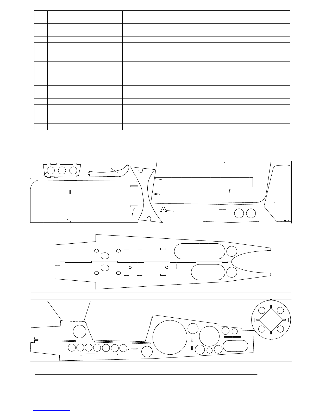
Positionsnummern der Laserteile
23
22
26
27
39
49
51
67
68
79
90
45
48
41
66
Page 56

56
GRAUPNER GmbH & Co. KG D-73230 KIRCHHEIM/TECK GERMANY
Keine Haftung für Druckfehler. Technische Änderungen vorbehalten! 04/2007
ID# 0057887
24
25
40
52
53
55
89
91
88
88
115
117
116
118
118
21
38 38
38
38
42
42
43
43
44
44
44 44
45
45 45
45
76
76
77
78
80
80
84
84
96
96
96
96
65
Page 57

57
GRAUPNER GmbH & Co. KG D-73230 KIRCHHEIM/TECK GERMANY
Keine Haftung für Druckfehler. Technische Änderungen vorbehalten! 04/2007
ID# 0057887
29
31
32
46
47
56
56
56
57
69
97
102
102
105
105
105
100
100
100
100
33
33
35
35
36
36
37
37
58
59
60
95
95
95
95
107
108
109
Page 58

58
GRAUPNER GmbH & Co. KG D-73230 KIRCHHEIM/TECK GERMANY
Keine Haftung für Druckfehler. Technische Änderungen vorbehalten! 04/2007
ID# 0057887
Einstellung des Modells
Ruderausschläge:
Schwerpunkt: 60 – 65 mm von der Nasenleiste der unteren Tragfläche nach hinten.
Erstflug: Laden sie die Akkus und Testen Sie die Funktion und Reichweite des Modells. Suchen Sie sich
einen Tag mit möglichst wenig (besser Windstille)aus. Nach dem Austrimmen des Modells und
dem Kennenlernen des Flugverhaltens können Sie mit den ersten Kunstflugfiguren beginnen.
Empfohlenes Zubehör
Nicht im Baukasten enthalten
1x COMPAKT 540 14,4 V Best.- Nr. 7721
4x Servo C5077 Best.- Nr. 3103 oder
4x Servo DS 3728 Best.- Nr. 5158 oder
4x Servo DS 3781 Best.- Nr. 5161
1x Empfänger R700 Best.- Nr. 3551 oder
1x Empfänger SMC 14 Best.- Nr. 7033
1x Antriebsakku 4 LiPo 2100 14,8V Best.- Nr. 7643.4
1x Regler Genius 70 Best.- Nr. 2897.G35
1x Ersatzluftschraubenblätter Best.- Nr. 1336.33.18
1x Luftschraubenaufnahme Best.- Nr. 7690.5
1x GFK- Luftschrauben- Zwischenstück Best.- Nr. 197.625
1x Hochlast- Servoarme Best.- Nr. 3544
1x Haken- und Schlaufenband Best.-Nr.3368.1
1x Luftschraubenmittelstück Best.-Nr. 6060.10
Fernlenkanlage
Ab MX 12 Best.- Nr. 7422
Geeignet sind auch andere Graupner JR/ 35 MHz FM – Fernlenkanlagen.
Optionales Zubehör und Werkzeug ( nicht im Baukasten enthalten)
1x Styropor Sekundenkleber Best.- Nr. 5820
1x Dünnflüssiger Sekundenkleber Best.- Nr. 5822
1x Dickflüssigen Sekundenkleber Best.- Nr. 5823
1x 5 min epoxy Devcon Best.- Nr. 961.28
1x UHU por Best.- Nr. 959
1x Aktivatorspray für Sekundenkleber Best.- Nr. 953.150
1x Glasfaserklebeband Best.- Nr. 98709
Höhenruder nach oben und unten 100mm
Seitenruder nach rechts und links 110mm
Querruder nach oben und unten 55mm
Page 59

59
GRAUPNER GmbH & Co. KG D-73230 KIRCHHEIM/TECK GERMANY
Keine Haftung für Druckfehler. Technische Änderungen vorbehalten! 04/2007
ID# 0057887
Building instructions for the PITTS S12 1400, Order No. 9570
The model
The GRAUPNER PITTS S12 is a model of the American aerobatic biplane, with “full-house”
controls and excellent aerobatic capability. The aeroplane’s performance, indoors and
outdoors, is limited only by the pilot’s skills on the sticks. The machine’s large control
surfaces make it capable of extreme 3-D manoeuvres as well as standard aerobatics.
Specification
Wingspan approx. 1400 mm
Overall length approx. 1510 mm
Wing area approx. 71,1 dm²
Wing loading approx. 21,6 g/dm²
Weight, according to fittings 1540g
GRAUPNER GmbH & Co. KG D-73230 KIRCHHEIM/TECK GERMANY
No liability for printing errors. We reserve the right to introduce modifications. ID# 0057872 02/2007
Manufacturer’s declaration from Graupner GmbH & Co. KG
Content of the manufacturer’s declaration
If material defects or manufacturing faults should arise in a product distributed by us in the
Federal Republic of Germany and purchased by a consumer (§ 13 BGB), we, Graupner
GmbH & Co. KG, D-73230 Kirchheim/Teck, Germany, acknowledge the obligation to correct
those defects within the limitations described below.
The consumer is not entitled to exploit this manufacturer’s declaration if the failure in the
usability of the product is due to natural wear, use under competition conditions, incompetent
or improper use (including incorrect installation) or external influences.
This manufacturer’s declaration does not affect the consumer’s legal or contractual rights
regarding defects arising from the purchase contract between the consumer and the vendor
(dealer).
Extent of the guarantee
If a claim is made under guarantee, we undertake at our discretion to repair or replace the
defective goods. We will not consider supplementary claims, especially for reimbursement of
costs relating to the defect (e.g. installation / removal costs) and compensation for
consequent damages unless they are allowed by statute. This does not affect claims based
on legal regulations, especially according to product liability law.
Guarantee requirements
The purchaser is required to make the guarantee claim in writing, and must enclose original
proof of purchase (e.g. invoice, receipt, delivery note) and this guarantee card. He must send
the defective goods to us at his own cost, using the following address:
Page 60

60
GRAUPNER GmbH & Co. KG D-73230 KIRCHHEIM/TECK GERMANY
Keine Haftung für Druckfehler. Technische Änderungen vorbehalten! 04/2007
ID# 0057887
Graupner GmbH & Co. KG, Service Department,
Henriettenstr. 94 - 96, D-73230 Kirchheim / Teck, Germany
The purchaser should state the material defect or manufacturing fault, or the symptoms of the
fault, in as accurate a manner as possible, so that we can check if our guarantee obligation is
applicable.
The goods are transported from the consumer to us and from us to the consumer at the risk
of the consumer.
Duration of validity
This declaration only applies to claims made to us during the claim period as stated in this
declaration. The claim period is 24 months from the date of purchase of the product by the
consumer from a dealer in the Federal Republic of Germany (date of purchase). If a defect
arises after the end of the claim period, or if the evidence or documents required according to
this declaration in order to make the claim valid are not presented until after this period, then
the consumer forfeits any rights or claims from this declaration.
Limitation by lapse of time
If we do not acknowledge the validity of a claim based on this declaration within the claim
period, all claims based on this declaration are barred by the statute of limitations after six
months from the time of implementation; however, this cannot occur before the end of the
claim period.
Applicable law
This declaration, and the claims, rights and obligations arising from it, are based exclusively
on the pertinent German Law, without the norms of international private law, and excluding
UN retail law.
Important Safety Notes
You have acquired a kit which can be assembled into a fully working RC model when fitted
out with suitable accessories. However, we as manufacturers have no control over the way
you build and operate your RC model aircraft, nor how you install, operate and maintain the
associated components, and for this reason we are obliged to deny all liability for loss,
damage or costs which are incurred due to the incorrect use of our products or due to
incompetent behaviour on the part of the user, or which are connected with such operation in
any way. Unless otherwise prescribed by binding law, the obligation of the GRAUPNER
company to pay compensation, regardless of the legal argument employed, is excluded. This
includes personal injury, death, damage to buildings, damages due to loss of business or
turnover, interruption of business or other direct or indirect consequent damage whose root
cause was the operation of the model.
The total liability in all cases and under all circumstances is limited to the amount of money
which you actually paid for the model.
This model is built and flown at the sole and express responsibility of the operator.
The only way to avoid injury to persons and damage to property is to handle and
operate the model with the greatest care and consideration at all times.
According to the new regulation of §103 Paragraph 3 of the LuftVZO (German Aviation
Approvals Office), all model aircraft - whether slow-flyer, park-flyer, glider, or model aircraft
propelled by any form of power plant - must be insured before the model is operated. If you
are not sure about this, please ask at your local model shop where the staff will be glad to
Page 61

61
GRAUPNER GmbH & Co. KG D-73230 KIRCHHEIM/TECK GERMANY
Keine Haftung für Druckfehler. Technische Änderungen vorbehalten! 04/2007
ID# 0057887
advise you.
These safety notes must be kept in a safe place. If you ever dispose of the model, be sure to
pass them on to the new owner.
The following points are important and must be observed at all times:
• This model is not suitable for young persons under 16 years of age. Young people under
this age may safely operate the model, but only under the supervision of an adult or
guardian.
• All model flyers must behave in such a way that there is no danger of them
endangering or adversely affecting public safety and order, and especially other
people and property.
• The operator of the model must be in full possession of his or her bodily and mental
faculties. As with car driving, operating a model aircraft under the influence of alcohol or
drugs is not permissible under any circumstances.
• If you have any questions regarding the safe operation of your RC model aeroplane,
please turn to your local model shop in the first instance, as the staff will be pleased to
help you.
• Radio-controlled model aircraft are extremely demanding and potentially dangerous
objects, and require a high level of expertise, skill and responsibility from the operator.
• In legal terms our models are classed as aircraft, and as such are subject to legal
regulations and restrictions which must be observed at all times. Our brochure
“Modellflugrecht, Paragrafen und mehr” (Model Aviation Law, Legal Requirements and
more) is available under Order No. 8034.01, and contains a summary of all these rules.
Your local model shop should have a copy which you can read. There are also Post
Office regulations concerning your radio control system, and these must be observed.
Refer to your RC system instructions for more details.
• A radio-controlled model aircraft can only work properly and fulfil your expectations if it is
built very carefully and in accordance with the building instructions. If you wish to avoid
injuring people and damaging property it is essential to be careful and painstaking at all
stages of building and operating your model. Nobody would climb into a full-size aircraft
and try to fly it without undergoing training beforehand, and model flying is a skill which
also needs to be learned. We suggest that you ask an experienced model flyer for help,
or join a model club or flight training school. Your local model shop and the specialist
magazines are excellent sources of information. If at all possible, it is always best to join
a club and fly at the approved model flying site.
• If you are flying a model aircraft for the first time we strongly recommend that you ask an
experienced modeller to check the aeroplane first and be ready to help you during the
first few flights.
• Be sure to use only those parts included in the kit, together with other genuine Graupner
accessories and replacement parts as recommended expressly by us. Even if you
change a single component you can no longer be sure that the system will work reliably,
and such changes also invalidate your guarantee.
• Always read and observe the safety notes supplied with the batteries and the charger
when using and charging LiPo batteries.
• Never fly the model close to high-tension overhead cables, industrial areas, residential
areas, public roads, squares, school playgrounds, parks and playing fields etc.
• If there are passers-by or spectators at your flying site, make sure that they are aware of
the dangers inherent in your activity before you start the motor, and insist that they keep
a safe distance away - at least 5 m behind the propeller plane.
• Always keep a safe distance away from people and objects when flying; never fly low
over people’s heads, and never fly directly towards them.
• Never fly your model in protected sites, animal or plant sanctuaries or sites of special
scientific interest (SSSIs).
Page 62

62
GRAUPNER GmbH & Co. KG D-73230 KIRCHHEIM/TECK GERMANY
Keine Haftung für Druckfehler. Technische Änderungen vorbehalten! 04/2007
ID# 0057887
• Never fly the model in adverse conditions, e.g. rain, storm or strong wind, or
temperatures below -5°C or above +35°C.
• Before you fly the model check that the radio control system is working reliably, and that
all connections are firmly seated.
• Use only matching polarised electrical connectors. The flight battery, all cables and
connectors must be insulated carefully to prevent short-circuits, especially if you make
them up yourself. Never combine connectors with contacts of different materials, e.g. tinplated and gold-plated, as the connections will not be reliable in the long-term.
• The batteries must be given a full charge before the model is flown, and it is important to
check the effective range of the radio control system. It is particularly important that the
transmitter should be fully charged before each flying session.
• Ensure that the frequency you intend to use is not already in use by other modellers.
Never fly your model if you are not certain that your channel is free. If there are other
modellers in the vicinity, ask them specifically which channels they are using.
• Read and observe the instructions and recommendations supplied with your radio control
system and accessories.
• Always disconnect the power system from the flight battery before carrying out any work
on these components.
• When the drive battery is connected keep well clear of the area around the propeller,
as this represents the greatest risk of accident and injury. Make sure any spectators do
the same.
• Do not be tempted to exceed the recommended operating voltage. Higher voltages may
cause the motor to overheat, and the electrical cables may even melt. If this should
happen, the model could easily be ruined or even catch fire.
• Ensure that all the power system components are free-moving.
• Check that your servos are not mechanically obstructed at any point in their full travel.
• Dry cells and rechargeable batteries must never be short-circuited - fire hazard.
• Allow the motor and speed controller to cool down after every flight. Take care not to
touch the hot parts.
• Remove the rechargeable battery if the model is to be transported, or will not be used for
a long period.
• Do not subject the model to high levels of humidity, heat, cold or dirt, and never leave it in
a hot car in the Summer.
• Secure the model and your RC equipment carefully when transporting them. They may
be seriously damaged if they are free to slide about,.
• If you have to recover the model after an out-landing, take care not to risk your own
life or that of others.
Care and maintenance
• Clean the model carefully after every session.
• Clean the model and the radio control components using suitable cleaning agents only.
Ask your local model shop if you are not sure.
Notes on building the model
• Before you start construction it is essential to read right through these instructions, using
the Parts List constantly as a reference. In general terms the Building Instructions and
the Parts List reflect the sequence of assembly. Be sure to study the stage photos when
building, as they are a valuable source of additional information.
• Bear in mind the possible hazards involved in the use of tools.
• You will need a sanding block for sanding the edges of the pre-cut Depron parts, and for
chamfering the edges of hinged panels. Make this by sticking abrasive paper to a flat
wooden block using double-sided adhesive tape. 120-grit and 240-grit abrasives have
Page 63

63
GRAUPNER GmbH & Co. KG D-73230 KIRCHHEIM/TECK GERMANY
Keine Haftung für Druckfehler. Technische Änderungen vorbehalten! 04/2007
ID# 0057887
proved ideal.
• Deploy all cables neatly, wherever possible without crossing them over. It is of
fundamental importance never to allow a positive wire to make electrical contact with a
negative wire. Deploy all motor cables in such a way that there is no chance of them
contacting any rotating parts of the power system. Use cable ties or adhesive tape for
this.
• Deploy the receiver aerial as far from all high-current wires as possible (at least 3 cm).
• Please ensure that the only materials to make contact with the Depron surfaces are
foam-compatible adhesives and cleaning agents, as other solvents may dissolve and
destroy the surface.
• Recommended adhesives for gluing various materials:
Material - material Suitable adhesives
Plastic generally - Depron Foam cyano / UHU por
Depron - Depron Foam cyano / UHU por
Depron - metal Foam cyano / UHU por
Read and observe the instructions supplied with all adhesives! The building instructions inform you
when to use particular glues. If you wish to use white spirit or other solvent as a cleaning agent, note
that special safety measures are required. Read the instructions supplied with these materials.
Assembly instructions
1. Cut out the Parts List from the instructions, and the page showing the part numbers of
the laser-cut components, so that you always have direct access to this information
during the building process. This will make construction easier, and help you to
understand the instructions.
2. The first step should be to cut all the CFRP (carbon fibre) rods to the lengths stated in the
Parts List. Please keep to the sequence stated in the Parts List. Unless the
material is to be glued using UHU-por, we recommend that you sand the material
lightly at all joint positions to provide a “key” for the adhesive.
3. Glue together the four connecting wedges (21) in pairs using cyano-acrylate glue
(“cyano”).
4. Sand the wing joiner tubes (7) lightly, and glue the connecting wedges (21) to them, flush
with the end of the tubes.
5. Glue the wing joiner tubes (7) in the wing panels (22, 23) using 5-minute epoxy, as
shown in the following pictures.
6. The wings can now be glued to the wing centre sections (24, 25). Allow the glue to set
hard, then cut through the joiner tubes (7) in the centre using a fretsaw. Do not sand
the ends of the joiner tubes flush at this point; this is carried out when the wings
are complete.
7. Mark, say, the top left and bottom left wing panels to ensure that you join the correct
panels later. Lightly sand the wing trailing edge reinforcements (14) at one end over a
length of 40 mm.
8. Sand back the connecting wedges (21) and the wing joiner tubes (7) flush with the trailing
edge of the wing (top wings only).
Page 64

64
GRAUPNER GmbH & Co. KG D-73230 KIRCHHEIM/TECK GERMANY
Keine Haftung für Druckfehler. Technische Änderungen vorbehalten! 04/2007
ID# 0057887
9. Apply UHU-por to the wing panels and the wing reinforcements (14), and allow the glue
to air-dry. Take care to apply the UHU-por only to the non-sanded parts and the
Depron® components, as the sanded parts will be glued using high-viscosity
cyano-acrylate (“thick cyano”). This applies to all stages which are similar to this
procedure.
10. Apply thick cyano to the sanded area of the wing trailing edge reinforcement, and glue
the reinforcement to the trailing edge of the wing. Note that the top wing is longer
than the bottom wing, and so the reinforcements are shorter. Glue the
reinforcements to the joiner tubes first, as shown in the pictures. Allow the glue to
set hard, then sand back the joiner tubes and the carbon reinforcements flush with the
wing.
11. Chamfer the leading edge of the ailerons (26, 27) at 45°, and attach them to the wings
using the glass fibre adhesive tape (28). Take care to produce a handed pair of
ailerons: they are different left and right. Apply short pieces of tape to the underside
of the hinge line to secure the inboard and outboard hinges.
12. Screw the ball-end bolts (30) into the aileron horns (29), and glue the horns in the slots in
the bottom ailerons. Note that the linkage balls must face outward.
13. Attach the front strut supports (31) and the rear strut supports (32) to the wing centre
section supports (33) using thick cyano. Take care to produce a handed pair (one left
and one right component).
14. Lightly sand the right and left ends of one face of the wing centre section reinforcements
(16), and glue these to the top and bottom wing centre sections (24, 25) as described in
Stages 9 + 10.
15. Insert the aluminium threaded sleeves (34) in the centre section supports (33) and glue
the supports to the top wing centre section (24). The threaded sleeves are only
required at this moment for aligning the supports; they are glued in place at a
later stage.
16. Glue the rigging supports (35) in place using the same method, then sand back the joiner
tubes etc. flush with the wing centre sections.
17. To avoid errors when assembling the right and left wing struts, we suggest that you lay
out all the parts for the strut assemblies as shown in the picture:
Carbon strut reinforcements (15), top strut end supports (36), bottom strut end supports
(37), strut guides (38) and struts (39).
18. Insert the threaded sleeves (34) in the strut end supports (36, 37), and glue the strut
guides (38) to the strut end supports (36, 37) using thick cyano, aligning the parts with
the threaded sleeves (34). Ensure that no glue gets onto the threaded sleeves, as
these parts are only used for alignment; it should be possible to remove them
once the glue has hardened. Now glue the complete strut support assemblies in the
ends of the wing struts (39) using UHU-por, flush with the top or bottom edge of the
Depron parts.
19. Glue the strut reinforcements (15) to the wing struts (39) using UHU-por; glue them to the
hardwood supports using cyano.
Page 65

65
GRAUPNER GmbH & Co. KG D-73230 KIRCHHEIM/TECK GERMANY
Keine Haftung für Druckfehler. Technische Änderungen vorbehalten! 04/2007
ID# 0057887
20. Glue the fin (40) to the fuselage spine (41) using UHU-por. Sand the trailing edge of the
fin to a chamfer of about 15°, and glue the carbon rudder reinforcement (17) to the
chamfered face using UHU-por, flush with the acute edge of the Depron.
21. Glue the large locating plates (42) to the undercarriage supports (43), and the small
locating plates (44) to the cabane supports (45) using thick cyano. Take care to line up
the locating plates exactly with the marked lines.
22. Before carrying out the next two stages, please follow the illustrations very
carefully so that the servo holder and the plywood pieces are glued to the correct
side of the longeron. Glue one of the servo mounts (46 or 47; if 47, centre it in the
opening) over the aperture in the left-hand fuselage side panel (45) using UHU-por.
23. glue the cabane supports and the undercarriage supports in the left and right fuselage
side panels (45, 48) using UHU-por. Note that the undercarriage supports should be
splayed out at the front.
24. Glue the fuselage side panels (45, 48) to the central fuselage spine (41) using UHU-por.
25. Slide the bottom wing centre section into the fuselage framework.
26. Fit the support formers (49) in the slots using light pressure, then adjust the position of
the centre section so that the support formers (49) are exactly at right-angles to the
wing centre section and the fuselage when viewed from the nose.
27. Glue the snake outer sleeves (50) in the pushrod guides (51, 52) using foam cyano. Glue
the rudder pushrod guide (52) in the bottom slot in the left-hand side of the fuselage
spine, and the elevator pushrod guides in the opposite slot from both sides.
28. Sand the trailing edge of the tailplane (53) to a chamfer of about 15°, and glue the carbon
tailplane reinforcement (18) to the angled face using UHU-por, flush with the acute edge
of the Depron.
29. The tailplane (53) can now be glued to the fuselage using foam cyano, taking care to
keep it at 90° to the central fuselage spine. You will find laser-cut 6 mm Ø semi-circles
in the front and rear of the tailplane (53) which are intended to help you position the
panel accurately.
30. Open up the tailwheel unit (54) to an angle of about 91°. To check the angle, insert the
horn (56) in the rudder (55); the tailwheel unit should now lie parallel to the horn and the
slot.
31. Glue the short in-fill piece (58) to the bottom left-hand corner of the tailwheel unit support
(57) using thick cyano; position it flush with the long side. Place the tailwheel unit
against the short in-fill piece (58) and glue the long in-fill piece (59) in place, gluing the
tailwheel unit (54) at the same time. Glue the second tailwheel unit support (57) on top
to complete the sealed box.
32. Sand the leading edge of the rudder (55) to a 45° chamfer, and glue the horn in the slot
using foam cyano.
33. Glue the tailwheel assembly in the slot in the rudder, and to the rudder horn (56). Glue
the supplementary reinforcement (60) in place using UHU-por and thick cyano.
Page 66

66
GRAUPNER GmbH & Co. KG D-73230 KIRCHHEIM/TECK GERMANY
Keine Haftung für Druckfehler. Technische Änderungen vorbehalten! 04/2007
ID# 0057887
34. Attach the rudder to the fuselage spine and the fin using glass fibre adhesive tape, and
apply two short pieces of tape to the opposite side to secure the hinges.
35. Mount the heavy-duty servo output arms (61), the rubber grommets and the metal
spacers on the servos. Cut down the output arms and clean up the cut edges as shown
in the following pictures.
36. Glue the rudder servo in the fuselage using UHU-por, positioning the output arm in the
centre of the slot.
37. Lightly sand both ends of the rudder pushrod (3) and glue a metal threaded coupler (62)
to it using thick cyano. Screw a steel clevis (63) on the coupler. Ensure that the
pushrod is inserted to the full depth of the threaded coupler; the same applies to
all other stages which are similar to this procedure.
38. Slip the rudder pushrod (3) through the snake outers, glue it into the second threaded
coupler, and connect the clevises to the servo output arm and the rudder horn.
39. Important: cut two pieces of glass-fibre adhesive tape (28) about 240 mm long and stick
them to both sides of the motor dome; they should be parallel to the outside edges, and
spaced about 15 mm from them.
40. Select two magnets (64) and check that they attract each other, then glue the in-fill
pieces (65) on both sides of them using thick cyano; keep the edges flush. Repeat the
procedure with the second pair of magnets. Mark the magnet pairs, so that you can be
sure they will attract.
41. Separate the magnet pairs from each other, and glue one of each pair in the slots in the
front fuselage former (66) using foam cyano; the magnets should be fitted with the
attracting face flush with the fuselage former (66).
42. Press the fuselage former onto the fuselage framework from the front, and glue the parts
together using foam cyano.
43. Glue the servo mount (46 or 47) to the bottom motor dome reinforcement (67) using
UHU-por, and sand the edges of the motor dome reinforcements (67 and 68) to a 45°
chamfer. Remember to produce two handed pairs (different left and right).
44. Glue the motor dome reinforcements to the fuselage framework using UHU-por and foam
cyano, as shown in the pictures.
45. Glue the plywood motor bulkhead (69) to the motor dome using UHU-por, and apply a 50
mm length of glass fibre tape (28) to the joints to reinforce them.
46. Remove the ball from the ball-link (70) and attach it to the servo output arm using the
machine screw (71).
47. Glue a threaded coupler (62) to the front elevator pushrod 2 (20), and screw a clevis (63)
on the coupler. Fit the pushrod through the central hole in the Duo pushrod connector
(72), and tighten the grubscrew (73) to secure it. Connect the pushrod to the output arm
of the elevator servo.
48. Fix the aileron and elevator servos to the fuselage framework using the retaining screws
Page 67

67
GRAUPNER GmbH & Co. KG D-73230 KIRCHHEIM/TECK GERMANY
Keine Haftung für Druckfehler. Technische Änderungen vorbehalten! 04/2007
ID# 0057887
supplied with the servos. Deploy the servo leads as shown in the illustrations.
49. Use a knife to pierce slots in the left and right fuselage shells (74 and 75) at the marked
points to accept the cabane struts and the undercarriage legs. Open up the slots to the
correct size using the carbon rods. Take care not to cut the slots longer than the
marked size.
50. Sand the plywood undercarriage doublers (76) to match the curvature of the fuselage,
and glue them in place using UHU-por. The slots in the fuselage and the undercarriage
doublers should line up when viewed directly from above.
51. Glue the front and rear cabane doublers (77, 78) in place using UHU-por. Keep to the
dimensions stated in the photo.
52. Apply pieces of glass-fibre tape (28) over the doublers to reinforce the joints.
53. Before the next stage you should provisionally fit the fuselage shells over the basic
structure to establish where you have to press the shells into place. Lay the fuselage
structure on the bench, projecting over the edge as shown, and weight it down. Apply
UHU-por to the fuselage structure and the edges of the shell, and allow the adhesive to
air-dry for one or two minutes. Just before fitting the half-shell on the structure, apply
UHU-por to the edges of the side panel and the fuselage former (wet joint). Now fit the
half-shell and press it into place. Repeat the procedure with the second fuselage shell.
Then glue the elevator to the fuselage semi shells.
54. Chamfer the leading edge of the elevators (79) at 45° as shown. Glue the horns (56) in
the slots in the elevators using foam cyano.
55. Attach a threaded coupler and clevis to one end of each of the elevator pushrods (1).
Connect the prepared pushrods to the elevator horns, and apply the glass fibre tape
(28) as shown.
56. Slip the elevator pushrods into the fuselage through the outer sleeves and into the vacant
holes in the Duo pushrod connector. Offer up the elevators to the tailplane, and set
them to neutral (centre). Tighten the grubscrews in the Duo pushrod connector to clamp
the pushrods.
57. Sand the whole surface of the carbon undercarriage reinforcements (6), and lightly sand
the carbon undercarriage legs (5) over the length of the joint area with the
undercarriage reinforcements (6). Glue the two pairs of parts together using thick cyano,
taking care to keep the edges flush.
58. Drill a central 4 mm Ø hole at the end of each undercarriage leg at a point 15 mm from
the bottom edge. Pull the drill downward as shown, so as to obtain an angled hole; the
angle should be about 60°.
59. Insert the undercarriage legs in the fuselage (do not glue them), and fit the wheel axles
(9) in the angled holes. Lay a steel ruler between the right and left undercarriage legs,
and position the wheel axles parallel to the building board and with slight toe-in; tack the
axles to the legs with a little thin cyano. You can check that the angle is correct by
placing the undercarriage legs side by side as shown; the wheel axles should then be
about 2 mm apart at the top. When you are satisfied, apply 5-minute epoxy round the
axle joints to reinforce them.
Page 68

68
GRAUPNER GmbH & Co. KG D-73230 KIRCHHEIM/TECK GERMANY
Keine Haftung für Druckfehler. Technische Änderungen vorbehalten! 04/2007
ID# 0057887
60. Glue the wheel axle doublers (80) in the outer wheel spat shells (81, 82) using UHU-por,
lining up the holes carefully. Glue the inner wheel spat shells (83, 84) to the outer shells
(81, 82).
61. Slip two plywood locating rings (84) on each wheel axle, and fit the wheels in the wheel
spats. Slip the wheel spats and the wheels on the axles, and fit a further two locating
rings (84) on the axle to hold the parts in place.
62. Fit the grubscrew (73) in the collet (85) and screw it in by two full turns. Insert the brass
tubular rivet (86) in the tailwheel (87), fit the collet, and attach these parts to the
tailwheel unit.
63. Slide the undercarriage legs into the fuselage, position the wheel spats as shown in the
photo, and tack them to the legs using foam cyano. Remove the undercarriage from the
fuselage and glue the locating rings (84) to the wheel axle doublers and the wheel axles
using thin cyano. Now position the wheels in the spats, slide the locating rings into
position, and secure them with tiny drops of thin cyano. Take great care to avoid glue
running into the wheel hubs. Sand back the end of the wheel axles flush with the
spats.
64. Glue the undercarriage leg fairings (88) to the undercarriage using UHU-por; they should
be central relative to the wheel legs, and butt up against the wheel spats. Slide the
undercarriage units into the fuselage and shorten the fairings to the point where they
just rest against the fuselage. Do not glue the undercarriage units to the fuselage at
this stage.
65. Roughen the cabane struts (12, 13) at both ends over a distance of 3 mm, and insert the
struts in the fuselage. Place the top wing centre section on the cabane template and
insert the cabane struts in the appropriate slots.
66. Glue the cabane struts in place using thick cyano.
67. Carefully break off the jig sections of the cabane template, which are no longer needed.
68. Lightly sand the cabane braces (19) and the cabane struts. Check that the cabane
struts are a snug fit; it should not be necessary to press the struts into position.
Glue the cabane braces in place using foam cyano, thick cyano or 5-minute epoxy.
69. The undercarriage legs can now be sanded lightly, inserted, and glued to the fuselage.
70. Attach the remaining magnets from Stage 41 to the fuselage former. Fit the cowl former
(89) on the fuselage former and glue the magnets to the cowl former. Take care that
the cowl former makes good contact. Allow the glue to set hard, then separate the
cowl former from the fuselage again, using a steel ruler as a lever.
71. Lay the cowl former on the building board with the magnet side facing down. Fit the cowl
stringers (90) in the slots, and glue them in place using foam cyano. Add the cowl
reinforcing former (91) as shown, and secure it with foam cyano.
72. Use UHU-por to glue the cowl shells (92) to the cowl former (90), keeping the edges
flush. If there is a slight gap between the fuselage and the cowl when you fit the
moulding on the fuselage, you can push the cowl gently against the fuselage and rub
Page 69

69
GRAUPNER GmbH & Co. KG D-73230 KIRCHHEIM/TECK GERMANY
Keine Haftung für Druckfehler. Technische Änderungen vorbehalten! 04/2007
ID# 0057887
the parts together to obtain a closer fit; for technical reasons there is no other way of
closing the gap.
73. Cut out the oil cooler shells (93, 94) slightly oversize, i.e. working just outside the marked
lines. Glue the shells together using UHU-por and cut out the front opening once the
glue has set hard.
74. Cut a piece of 100-grit abrasive paper to an appropriate width and length and lay it on the
cowl as shown. Carefully rub the oil cooler against the glasspaper so that it takes up the
curvature of the cowl. Glue the oil cooler to the cowl at a point about 15 mm from the
rear edge using UHU-por.
75. Screw the ring-screws (95) into the threaded sleeves (34): fit four of the screws to their
full depth, and leave one full thread free for the remainder. Cut off the excess threaded
length of the ring-screws.
76. Epoxy the rigging supports in the top and bottom wing centre sections; check that it is still
possible to rotate the ring-screws.
77. Prepare the carbon wing rigging rods (10, 11) and connect them to the supports. The rod
(10) is hung in the canopy and rod (11) is hung in the lower wing.
78. Use UHU-por to glue the rigging doublers (95) to the wings, in line with the slots: attach
them to the top of the top wings, and the bottom of the bottom wings. Fit the strut
holders (96) through the doublers and the wings.
79. Slide the wing joiners (8) into the wings, and fit them on the fuselage. Attach the struts to
the strut holders, and slip the rigging supports through the struts and the strut holders.
Connect the rigging rods to the holders. Repeat this procedure on all the wings. Screw
the clevises on the rigging rods in or out in order to align the wings correctly. When you
are confident that all is well, fix the clevises to the rods with a drop of thin cyano. The
clevises can be opened and disconnected quickly and easily using the clevis opener
(97).
80. Press the strut holders against the doublers, and glue them in place using thick cyano.
Ensure that the holders are at the same angle as the struts.
81. Glue the threaded couplers (62) to the aileron pushrods (4). Screw the black ball-link (98)
on the one end, and the natural ball-link (99) on the other.
82. Press the ball-links onto the linkage balls on the aileron servos. Set the servos to neutral,
and screw the ball-links in or out to adjust the length of the pushrods until all the
ailerons are at neutral (centre).
83. Glue the link horns (100) in the notches in the ailerons using foam cyano.
84. The aileron link rods (2) can now be assembled: heat the plastic clevises (101) gently
using a heat-gun, and push them onto the carbon rods.
85. Connect the pushrods to the link horns and adjust them if necessary.
86. Insert the retaining screws (supplied with the motor) in the holes in the motor mounts
(102), and glue the two parts together using thick cyano. Don’t get glue on the
Page 70

70
GRAUPNER GmbH & Co. KG D-73230 KIRCHHEIM/TECK GERMANY
Keine Haftung für Druckfehler. Technische Änderungen vorbehalten! 04/2007
ID# 0057887
screws.
87. Install the motor; note the orientation as shown in the right-hand illustration.
88. Fit the retaining screws (103) in the motor mount.
89. Push the rubber grommets (104) onto the retaining screws, and attach the motor
assembly to the motor bulkhead (69).
90. Glue the magnets (64) in the slots in the spinner locating plates (105) using thin cyano,
keeping them flush with the surface of the plates. Check the orientation (attraction /
repulsion) of the magnets. Ensure that you make one right and one left part, and
check that the spinner can be mounted either way round.
91. Glue the magnets in the spinner backplate (106), keeping them flush with the surface,
and place the spinner locating plates on top.
92. Assemble the spinner formers (107, 108, 109) as shown in the photo. Insert the bottom
end of the formers in the retaining plates and the backplate, and tack the parts together
using thin cyano. Take care to avoid glue running between the plates. Allow the glue
to set hard, then separate the spinner backplate (106) from the internal spinner
framework, and apply thick cyano to all the joints to reinforce them.
93. Place the internal spinner framework in the spinner cap (110) and tack the parts together
using foam cyano. Allow the glue to set hard, then cut off the projecting spinner
material, leaving a slight excess; sand it back flush with the spinner backplate. Remove
the spinner backplate and apply more glue to the spinner framework to reinforce the
joints.
94. Attach the propeller hub (111) to the motor, then slide the spinner backplate and the
propeller spacer (112) on the motor shaft. Attach the propeller blades to the propeller
hub (113). Secure the blade holder screws with a drop of thread-lock fluid. Align
the propeller assembly on the spinner backplate as shown in the pictures, and fix the
parts together.
95. Extend the battery / speed controller leads by about 80 mm, and connect the speed
controller to the motor (yellow to yellow, red to black, and blue to red). Mount the
controller inside the fuselage using Velcro tape or UHU-por. Connect the speed
controller and servos to the receiver, and install the receiver in the fuselage, again using
Velcro tape or UHU-por. Deploy the receiver aerial inside the fuselage.
96. Stick one side of the Velcro tape (114) inside the fuselage, and the other side to the flight
battery.
97. Fold the propeller blades forward, and fit the cowl onto the fuselage. Now cut away the
spinner cap to clear the propeller blades, and attach the spinner to the backplate.
98. Lay the canopy frame (115) on the building board, underside facing down. The
underside is the engraved side. Use foam cyano to glue the magnets to it, flush with
the underside.
99. Glue the instrument panel support (116) to the instrument panel (117) using foam cyano,
then glue the instrument panel in the slots in the canopy frame, again using foam cyano.
Page 71

71
GRAUPNER GmbH & Co. KG D-73230 KIRCHHEIM/TECK GERMANY
Keine Haftung für Druckfehler. Technische Änderungen vorbehalten! 04/2007
ID# 0057887
100. Glue the magnets in the fuselage using foam cyano. Check beforehand that the
magnets attract those in the canopy frame, and do not repel them.
101. Bend the canopy frame upward at the engraved line, and apply a little foam cyano on
both sides of the resultant gap. Apply the adhesive only in the centre; leave about
25 mm unglued at each end. Place the canopy frame on the fuselage and allow the
foam cyano to set hard.
102. Apply glass fibre tape to reinforce the angled area.
103. If you wish, the canopy frame can now be painted. Painting should be carried out at this
stage, as it may be difficult or even impossible at a later stage.
104. Stick the decals on the canopy frame and the pilot heads (118).
105. Glue the pilot in the canopy frame using foam cyano or UHU-por.
106. Cut out the canopy (119) along the marked lines.
107. Place the canopy frame on the fuselage and trim it to follow the curvature of the top
decking. Check at intervals that the canopy (119) still fits over the frame.
108. The next stage requires two pairs of hands to avoid soiling the canopy with excess
adhesive. Mark the position of the canopy on the fuselage, using the fuselage joint line
and the canopy frame as a guide. Apply UHU-por to both sides of the canopy frame,
then place the canopy over it and press it into place to transfer the adhesive. Remove
the canopy again and allow the glue to air-dry. Apply UHU-por to the canopy frame
formers. Fit the canopy, press it into position and leave the adhesive to set hard; it is
safe to remove the canopy again after about 10 to 15 minutes.
109. The canopy can either be painted using foam paints, or finished off with the decals
supplied.
Parts List
Part Description No. off Material Size, thickness and length in mm
1 Elevator pushrod (1) 2 Round CFRP rod 2 mm Ø x 575 mm
2 Aileron link rod 2 Round CFRP rod 2 mm Ø x 268 mm, remainder of
elevator pushrods
3 Rudder pushrod 1 Round CFRP rod 2 mm Ø x 590 mm
4 Aileron pushrod 2 Round CFRP rod 2 mm Ø x 230 mm, remainder of
rudder pushrod and part 2. of
the 330 mm CFRP rod supplied
5 Undercarriage leg 2 Flat CFRP strip 12 x 2.0 x 335 mm
6 Undercarriage reinforcement 2 Flat CFRP strip 12 x 2.0 x 80 mm, remainder of
undercarriage legs
7 Wing joiner tube 8 Square CFRP 6 x 6 x 4 I.D. x 85 mm
tube, 4 mm I.D.
8 Wing joiner rod 8 Round CFRP rod 4 Ø x 80 mm
9 Wheel axle 2 Round CFRP rod 4 Ø x 70 mm, remainder from
wing joiner
10 Wing rigging rod (1) 2 Round CFRP rod 1.6 Ø x 405 mm
11 Wing rigging rod (2) 2 Round CFRP rod 1.6 Ø x 420 mm
12 Front cabane strut 2 Flat CFRP strip 6 x 1 x 205 mm
13 Rear cabane strut 2 Flat CFRP strip 6 x 1 x 208 mm
14 Wing trailing edge reinforcement 4 Flat CFRP strip 6 x 1 x 2 mm, cut strips in half
15 Wing strut reinforcement 2 Flat CFRP strip 6 x 1 x 244 mm
16 Wing centre section reinforcement 2 Flat CFRP strip 6 x 1 x 198 mm, remainder from
Page 72

72
GRAUPNER GmbH & Co. KG D-73230 KIRCHHEIM/TECK GERMANY
Keine Haftung für Druckfehler. Technische Änderungen vorbehalten! 04/2007
ID# 0057887
strut reinforcement
17 Fin reinforcement 1 Flat CFRP strip 6 x 1 x 343 mm
18 Tailplane reinforcement 1 Flat CFRP strip 6 x 1 x 634 mm, remainder from
rudder reinforcement
19 Cabane brace 2 Flat CFRP strip 6 x 1 x 191 mm, from scrap
20 Elevator pushrod (2) 1 Round CFRP rod 2 Ø x 30 mm, from scrap
21 Connecting wedge 4 Birch Laser-cut, 3 mm
22 Top wing panel 2 Depron® Laser-cut, 6 mm thick
23 Bottom wing panel 2 Depron® Laser-cut, 6 mm thick
24 Top wing centre section 1 Depron® Laser-cut, 6 mm thick
25 Bottom wing centre section 1 Depron® Laser-cut, 6 mm thick
26 Top aileron 2 Depron® Laser-cut, 6 mm thick
27 Bottom aileron 2 Depron® Laser-cut, 6 mm thick
28 Glass fibre adhesive tape - Order No. 98709 As required; not included in the kit
29 Aileron horn 2 Beech Laser-cut, 2 mm thick
30 Ball-end bolt 2 Steel Ready made, M2 thread
31 Front strut support 2 Beech Laser-cut, 2 mm thick
32 Rear strut support 2 Beech Laser-cut, 2 mm thick
33 Wing centre section support 2 Beech Laser-cut, 1 mm thick
34 Threaded sleeve 8 Aluminium Machined part
35 Rigging support 2 Beech Laser-cut, 1 mm thick
36 Top strut end support 2 Beech Laser-cut, 1 mm thick
37 Bottom strut end support 2 Beech Laser-cut, 1 mm thick
38 Strut guide 4 Birch Laser-cut, 3 mm thick
39 Wing strut 2 Depron® Laser-cut, 6 mm thick
40 Fin 1 Depron® Laser-cut, 6 mm thick
41 Central fuselage spine 1 Depron® Laser-cut, 6 mm thick
42 Large locating plate 2 Birch Laser-cut, 3 mm thick
43 Undercarriage support 2 Birch Laser-cut, 3 mm thick
44 Small locating plate 4 Birch Laser-cut, 3 mm thick
45 Cabane support 4 Birch Laser-cut, 3 mm thick
45 Left fuselage side panel 1 Depron® Laser-cut, 6 mm thick
46 Servo mount, C 5077 3 Beech Laser-cut, 2 mm thick
47 Servo mount, DS 3728 or DS 3781 3 Beech Laser-cut, 2 mm thick
48 Right fuselage side panel 1 Depron® Laser-cut, 6 mm thick
49 Support former 2 Depron® Laser-cut, 6 mm thick
50 Snake outer sleeve 3 Hard PVC 3.2 x 2.2 mm, 70 mm long
51 Elevator pushrod guide 2 Depron® Laser-cut, 6 mm thick
52 Rudder pushrod guide 1 Depron® Laser-cut, 6 mm thick
53 Tailplane 1 Depron® Laser-cut, 6 mm thick
54 Tailwheel unit 1 Steel Pre-formed, 1.5 mm Ø
55 Rudder 1 Depron® Laser-cut, 6 mm thick
56 Horn 3 Beech Laser-cut, 2 mm thick
57 Tailwheel unit support 2 Beech Laser-cut, 2 mm thick
58 Short in-fill piece 1 Beech Laser-cut, 1 mm thick
59 Long in-fill piece 1 Beech Laser-cut, 2 mm thick
60 Supplementary rudder reinforcement 1 Beech Laser-cut, 1 mm thick
61 Heavy-duty servo output arm 4 Order No. 3544 Not included in the kit
62 Threaded coupler 17 Steel Machined
63 Clevis 13 Steel Pre-formed
64 Magnet 12 - 20 x 4 x 1.8 mm
65 In-fill piece for magnet 4 Birch Laser-cut, 3 mm thick
66 Front fuselage former 1 Depron® Laser-cut, 6 mm thick
67 Bottom motor dome reinforcement 2 Depron® Laser-cut, 6 mm thick
68 Top motor dome reinforcement 2 Depron® Laser-cut, 6 mm thick
69 Motor bulkhead 1 Beech Laser-cut, 2 mm thick
70 Ball-link 2 Plastic Inj. moulded, with brass ball
71 Cheesehead slot-head screw 2 Steel M2 x 8 mm
72 Duo pushrod connector 1 Aluminium Machined
73 Grubscrew 4 Steel M3 x 3 mm
74 Right fuselage shell 1 Depron® Vac.-moulded, 3 mm thick
75 Left fuselage shell 1 Depron® Vac.-moulded, 3 mm thick
76 Undercarriage doubler 2 Birch Laser-cut, 3 mm thick
77 Front cabane doubler 2 Birch Laser-cut, 3 mm thick
Page 73

73
GRAUPNER GmbH & Co. KG D-73230 KIRCHHEIM/TECK GERMANY
Keine Haftung für Druckfehler. Technische Änderungen vorbehalten! 04/2007
ID# 0057887
78 Rear cabane doubler 2 Birch Laser-cut, 3 mm thick
79 Elevator 2 Depron® Laser-cut, 6 mm thick
80 Wheel axle doubler 2 Birch Laser-cut, 3 mm thick
81 Outer right wheel spat shell 1 Depron® Vac.-moulded, 3 mm thick
82 Outer left wheel spat shell 1 Depron® Vac.-moulded, 3 mm thick
83 Inside right wheel spat shell 1 Depron® Vac.-moulded, 3 mm thick
84 Inside left wheel spat shell 1 Depron® Vac.-moulded, 3 mm thick
84 Locating ring 8 Birch Laser-cut, 3 mm thick
85 Collet 1 Brass 2.1 Ø x 6.0 mm
86 Brass tubular rivet 1 Brass 2 Ø x 0.2 x 15 mm
87 Tailwheel 1 - 15 mm Ø
88 Undercarriage leg fairing 2 Depron® Laser-cut, 3 mm thick
89 Cowl former 1 Depron® Laser-cut, 6 mm thick
90 Cowl stringer 1 Depron® Laser-cut, 6 mm thick
91 Cowl reinforcing former 1 Depron® Laser-cut, 6 mm thick
92 Cowl shell 2 Depron® Vac.-moulded, 3 mm thick
93 Right oil cooler shell 1 Depron® Vac.-moulded, 3 mm thick
94 Left oil cooler shell 1 Depron® Vac.-moulded, 3 mm thick
95 Rigging doubler 4 Beech Laser-cut, 1 mm thick
96 Strut holder 4 Birch Laser-cut, 3 mm thick
97 Clevis opener 1 Beech Laser-cut, 2 mm thick
98 Black ball-link 2 Plastic Inj. moulded
99 Natural ball-link 2 Plastic Inj. moulded
100 Aileron link rod horn 4 Beech Laser-cut, 2 mm thick
101 Plastic clevis 4 Plastic Inj. moulded
102 Motor mount 2 Beech Laser-cut, 2 mm thick
103 Motor mount retaining screw 3 Steel M3 x 16 mm, socket-head
104 Grommet 6 Rubber 7 x 4 x 3 mm
105 Spinner locating plate 2 Beech Laser-cut, 2 mm thick
106 Spinner backplate 1 Beech Laser-cut, 2 mm thick
107 Spinner former 1 Beech Laser-cut, 1 mm thick
108 Spinner former 1 Beech Laser-cut, 1 mm thick
109 Spinner former 1 Beech Laser-cut, 1 mm thick
110 Spinner cap 1 Depron® Vac.-moulded, 6 mm thick
111 Propeller hub 1 Order No. 7690.4 Not included in the kit
112 CFRP propeller spacer 1 Order No. 197.625 Not included in the kit
113 Propeller hub 1 Order No. 6060.10 Not included in the kit
114 Velcro tape 1 Order No. 3368.1 Not included in the kit
115 Canopy frame 1 Depron® Laser-cut, 3 mm thick
116 Instrument panel support 1 Depron® Laser-cut, 3 mm thick
117 Instrument panel 1 Depron® Laser-cut, 3 mm thick
118 Pilot’s head 2 Depron® Laser-cut, 3 mm thick
119 Canopy 1 ABS Vac.-moulded, 0.5 mm thick
Numbers of the laser-cut parts
Model set-up
Control surface travels
Elevator 100 mm up, 100 mm down
Rudder 110 mm right, 110 mm left
Ailerons 55 mm up, 55 mm down
Centre of Gravity: 60 - 65 mm aft of the bottom wing root leading edge.
First flight: Charge the batteries, check all the model’s working systems, and carry
out a range check. Wait for a day with as little air movement as possible
(flat calm is best). Trim the model out and take your time to become
accustomed to its handling, before gradually exploring its aerobatic
Page 74

74
GRAUPNER GmbH & Co. KG D-73230 KIRCHHEIM/TECK GERMANY
Keine Haftung für Druckfehler. Technische Änderungen vorbehalten! 04/2007
ID# 0057887
capabilities.
Recommended accessories
Not included in the kit
1 x COMPACT 540 14.4 V Order No. 7721
4 x C5077 servo Order No. 3103, or
4 x DS 3728 servo Order No. 5158, or
4 x DS 3781 servo Order No. 5161
1 x R700 receiver Order No. 3551, or
1 x SMC 14 receiver Order No. 7033
1 x LiPo flight battery, 2100 mAh / 14.8 V Order No. 7643.4
1 x Genius 70 speed controller Order No. 2897.G35
1 x Replacement propeller blades Order No. 1336.33.18
1 x Propeller hub Order No. 7690.5
1 x GRP propeller spacer Order No. 197.625
1 x Heavy-duty servo output arm Order No. 3544
1 x Velcro tape Order No. 3368.1
1 x Propeller hub Order No. 6060.10
Radio control system
Min. mx-12 Order No. 7422
Other Graupner/JR 35 MHz FM radio control systems are also suitable.
Optional accessories and tools (not included in the kit)
1 x Styrofoam cyano-acrylate glue (“foam cyano”) Order No. 5820
1 x Thin cyano-acrylate glue (“thin cyano”) Order No. 5822
1 x Thick cyano-acrylate glue (“thick cyano”) Order No. 5823
1 x Devcon 5-minute epoxy Order No. 961.28
1 x UHU-por adhesive Order No. 959
1 x Cyano-acrylate activator spray Order No. 953.150
1 x Glass fibre adhesive tape Order No. 98709
Item numbers of the laser components
Page 75

75
GRAUPNER GmbH & Co. KG D-73230 KIRCHHEIM/TECK GERMANY
Keine Haftung für Druckfehler. Technische Änderungen vorbehalten! 04/2007
ID# 0057887
Instructions de montage pour le modèle PITTS S12 1400, Réf. N°9570
Description du modèle
Le PITTS S12 GRAUPNER est une reproduction du biplan de voltige américain. Ce modèle est totalement apte
à la voltige et piloté sur les trous axes. Aussi bien en extérieur qu’en salle, ses seules limites sont les
connaissances du pilote. Grâce aux gouvernes de grande surface, la voltige extrême en 3D pourra aussi être
effectuée.
Caractéristiques techniques
Envergure, env. 1400 mm
Longueur hors-tout, env. 1510 mm
Surface alaire, env. 71,1 dm²
Charge alaire, env. 21,6 g/dm²
Poids en ordre de vol,
selon équipement 1540g
Conditions de garantie:
La garantie comprend la réparation gratuite ou l'échange des pièces présentant un défaut
de fabrication ou de matière pendant une durée de 24 mois, à compter de la date de
l'achat. Toutes autres réclamations sont exclues. Les frais de transport et d'emballage
sont à la charge de l'acheteur. Nous déclinons toute responsabilité pour les détériorations
survenues au cours du transport. Le retour au Service après Vente GRAUPNER, ou du
Pays concerné doit être accompagné d'une description du défaut constaté et de la facture
correspondante avec la date de l'achat. Le bénéfice de la garantie sera perdu lorsque le
défaut de la pièce ou du modèle sera dû à un accident, à une manipulation incorrecte ou
à une mauvaise utilisation
Conseils de sécurité importants
Vous avez fait l'acquisition d'une boite de construction avec les accessoires correspondants
qui vont vous permettre la réalisation d'un modèle radiocommandé. Le respect des
instructions de montage et d'utilisation relatives au modèle ainsi que l'installation, l'utilisation
et l'entretien des éléments de son équipement ne peuvent pas être surveillés par la Firme
GRAUPNER. C'est pourquoi nous déclinons toute responsabilité concernent les pertes, les
dommages ou les coûts résultants d'une mauvaise utilisation ou d'un fonctionnement
défectueux. Tant qu'elle n'y a pas été contrainte par le législateur, la responsabilité de la
Firme GRAUPNER n'est aucunement engagée pour les dédommagements (incluant les
dégâts personnels, les cas de décès, la détérioration de bâtiments ainsi que le
remboursement des pertes commerciales dues à une interruption d'activité ou à la suite
d'autres conséquences directes ou indirectes) provenant de l'utilisation du modèle.
L'ensemble de sa responsabilité est en toutes circonstances et dans chaque cas strictement
limitée au montant que vous avez réellement payé pour ce modèle.
Page 76

76
GRAUPNER GmbH & Co. KG D-73230 KIRCHHEIM/TECK GERMANY
Keine Haftung für Druckfehler. Technische Änderungen vorbehalten! 04/2007
ID# 0057887
L'utilisation du modèle se fait uniquement aux risques et périls de son utilisateur.
Seule une utilisation prudente et responsable évitera de causer des dégâts
personnels et matériels.
Les modèles motorisés de tous genres doivent être assurés avant leur utilisation. Contractez
pour cela une assurance spéciale pour les modèles radiocommandés. Demandez à votre
revendeur qui vous renseignera volontiers.
Ces conseils de sécurité devront être soigneusement conservés et remis à l’acheteur en cas
de revente du modèle.
Les points suivants devront être impérativement observés :
• Ce modèle ne convient pas aux enfants en dessous de 16 ans. Les jeunes gens
insuffisamment âgés devront utiliser le modèle uniquement sous la surveillance d’un
adulte compétent.
• Chaque modéliste doit se comporter de façon à ce que l'ordre et la sécurité publiques,
vis-à-vis des autres personnes et des biens, ainsi que l'activité des autres modélistes ne
soient pas mis en danger, ni perturbés.
• L'utilisateur doit être en pleine possession de ses facultés physiques et mentales.
Comme pour la conduite des automobiles, le pilotage des modèles volants sous l'effet de
l'alcool ou de la drogue n'est pas autorisé.
• Demandez à votre revendeur les mesures de sécurité à prendre avec l’utilisation d’un
modèle R/C, il vous renseignera volontiers.
• Les modèles d'avions R/C sont des appareils pouvant être dangereux et qui exigent de
leur utilisateur une grande compétence et la conscience de sa responsabilité.
• Un modèle volant R/C ne peut évoluer correctement que s'il a été construit et réglé
conformément aux instructions de montage et seule une utilisation prudente et
responsable évitera de provoquer des dommages matériels ou corporels. Le pilotage sûr
d’un modèle réduit n’est possible qu’après un entraînement ou un écolage appropriés.
Faites-vous assister par un modéliste expérimenté, ou inscrivez-vous dans une
association ou dans une école de pilotage. Consultez pour cela votre revendeur et la
Presse spécialisée. Le mieux est de faire partie d'un club d'aéromodélisme pour pouvoir
voler sur un terrain autorisé.
• Pour les premiers essais d’un modèle volant, il est toujours avantageux d’avoir un aide
expérimenté à se côtés pour assister les premiers vols.
• Il conviendra d'utiliser exclusivement les éléments fournis dans la boite de construction
ainsi que les accessoires d'origine Graupner et les pièces détachées conseillées. Si un
seul composant de la propulsion est remplacé, une parfaite sécurité de fonctionnement
de peut plus être assurée et peut entraîner la perte du bénéfice de la garantie.
• Observez toujours les prescriptions de sécurité pour l’utilisation et la charge des accus
LiPo ; celles-ci sont jointes avec les accus et le chargeur correspondant.
• Ne faites jamais voler votre modèle à proximité des lignes à haute tension, dans les
zones industrielles, les agglomérations, sur les voies publiques, les places, dans les
cours d'école, les parcs et les aires de jeux, etc…
• Avant de faire voler votre modèle, informez tous les passants et les spectateurs sur les
dangers qu'il peut présenter et demandez-leur de se tenir à une distance de sécurité d’au
moins 5 m derrière le champ de rotation de l’hélice.
• Tenez-vous à une distance de sécurité suffisante de personnes ou d'objets; ne survolez
jamais de personnes à basse altitude et ne volez jamais dans leur direction !
• Ne faites jamais évoluer votre modèle dans une nature protégée
• Ne volez jamais par de mauvaises conditions atmosphériques, par ex. sous la puis, un
orage, un vent fort ou par des températures en dessous de -5°C ou de +35°C.
Page 77

77
GRAUPNER GmbH & Co. KG D-73230 KIRCHHEIM/TECK GERMANY
Keine Haftung für Druckfehler. Technische Änderungen vorbehalten! 04/2007
ID# 0057887
• Avant chaque utilisation du modèle, vérifiez le bon fonctionnement de l’installation R/C
ainsi que le ferme branchement de tous les connecteurs.
• Utilisez toujours des connecteurs adaptés entre eux avec sécurité contre les inversions
de polarité. Tous les conducteurs de courant, les connexions ainsi que les batteries de
confection personnelle devront être isolés contre les court circuits. Ne combinez jamais
des connecteurs différents, par ex. des contacts en tôle avec des contacts dorés, car ici
aucune sécurité de fonction ne pourra être garantie.
• Les accus d’émission et de propulsion devront être chargés avant chaque utilisation et la
portée de l’installation R/C devra être vérifiée.
• Assurez-vous que la fréquence que vous utilisez est libre. Ne faites jamais voler votre
modèle tant que vous n’êtres pas sûr que votre fréquence n’est pas déjà occupée.
Lorsque d’autres modélistes se trouvent sur place, demandez-leur la fréquence qu’ils
utilisent.
• Observez les conseils donnés dans les instructions d’utilisation de votre ensemble R/C et
de ses accessoires.
• Travaillez sur la propulsion uniquement avec l’alimentation du moteur déconnectée.
• Lorsque l’accu de propulsion est connecté, ne vous tenez jamais vous-même ni d’autres
personnes dans le champ de rotation de l’hélice car elle présente un sérieux danger de
blessure.
• La tension d’alimentation conseillée ne devra pas être dépassée. Une tension trop élevée
peut faire surchauffer le moteur et le régulateur, ou les conducteurs électriques peuvent
fondre. Le modèle peut ainsi prendre feu et être détruit.
• Veillez à la libre rotation de la propulsion.
• Veillez à ce que les servos puissent se déplacer sur la totalité de leur course, sans
limitation mécanique.
• Les batteries et les accus ne devront pas être mis en court-circuit, ni en contact direct
avec de l’eau.
• Laissez le moteur et le régulateur de vitesse se refroidir après chaque utilisation. Touchez
le moins possible ces éléments échauffés.
• Retirez les accus pour le transport et lorsque le modèle n’est pas utilisé.
• Ne soumettez pas le modèle à une forte humidité, une chaleur ou un froid excessifs, ainsi
qu’aux salissures. Ne laissez pas le modèle dans une voiture surchauffée en été.
• Protégez le modèle et les éléments R/C durant le transport.
Entretien
• Nettoyez le modèle après chaque utilisation.
• Nettoyez le modèle et les éléments R/C uniquement avec un produit de adapté.
Renseignez-vous pour cela auprès de votre revendeur
Conseils pour la construction du modèle
• Lisez entièrement ces instructions avant de commencer les assemblages du modèle. Les
photos de montage seront utilisées en complément, car elles apportent des informations
supplémentaires.
• Veillez aux dangers possibles avec l’utilisation des outils.
• Pour pouvoir surfacer ou biseauter les pièces découpées en Depron, collez du papier
abrasif sur un morceau de bois lisse avec de la bande adhésive double face ; les grains
120 et 240 conviennent le mieux.
• Disposez proprement le câblage électrique sans faire de croisements. Les conducteurs
Plus ne doivent en aucun cas venir en contact avec les conducteurs Moins. Fixez tous les
fils vers le moteur de façon à ce qu’ils ne puissent pas toucher les pièces en rotation de la
propulsion, par ex. avec des colliers d’attache ou de la bande adhésive.
Page 78

78
GRAUPNER GmbH & Co. KG D-73230 KIRCHHEIM/TECK GERMANY
Keine Haftung für Druckfehler. Technische Änderungen vorbehalten! 04/2007
ID# 0057887
• Eloignez le plus possible le fil d’antenne de réception des conducteurs de courant de forte
intensité (au moins à 3 cm).
• Veillez à ce que seuls des colles et des produits de nettoyage compatibles avec le
Styropor viennent en contact avec les surfaces en Depron, car le solvant qu’ils
contiennent pourrait dissoudre et détruire cette matière.
• Colles conseillées pour le collage des matières :
Matière sur matière Colles conseillées
Plastique en général - Depron Colle seconde pour Styropor/ UHU POR
Depron sur Depron Colle seconde pour Styropor/ UHU POR
Depron sur Métal Colle seconde pour Styropor/ UHU POR
Observez le mode d’emploi des colles! Veillez aux conseils particuliers pour l’utilisation des qualités de colles
indiqués dans les instructions de montage. Des précautions particulières sont à prendre pour l’utilisation de
l’alcool et des autres solvants ; se référer à chaque mode d’emploi.
Instructions de montage
1. Pour une simplification et une meilleure compréhension des assemblages, découpez la liste des pièces et
la page avec les numéros des pièces découpées au Laser dans ces instructions pour avoir un accès direct
au cours des différents stades de montage.
2. Couper tout d’abord toutes les tiges en fibre de carbone à la longueur indiquée dans la liste des pièces.
Pour cela, observer l’ordre dans la liste des pièces. Pour obtenir une meilleure liaison des pièces en
fibre de carbone, elles ne devront pas être collées avec de la UHU por et les surfaces de collage
devront être poncées avec d’effectuer celui-ci.
3. Coller entre elles deux des quatre clavettes de liaison (21).
4. Poncer les tubes de jonction d’aile (7). Coller les clavettes de liaison (21) de niveau avec l’extrémité des
tubes de jonction d’aile.
5. Coller les tubes de jonction (7) dans les panneaux d’aile (22, 23) avec de la colle epoxy 5 minutes, comme
montré sur les illustrations suivantes.
6. Coller maintenant les panneaux d’aile avec les parties centrales (24, 25) et séparer les tubes de jonction (7)
dans le milieu avec une scie. Ne pas encore poncer de niveau les extrémités dépassantes des tubes
de jonction ; ceci se fera après avoir complété les ailes.
7. Repérer par ex. le panneau d’aile supérieure gauche et le panneau d’aile inférieure gauche pour garantir un
positionnement ultérieur exact des ailes. Poncer ensuite les renforts d’aile (14) sur une largeur de 40mm sur
un côté.
8. Poncer les clavettes de liaison (21) et les tubes de jonction (7) de niveau avec le bord de fuite de l’aile
(nécessaire seulement sur l’aile supérieure).
9. Enduire les panneaux et les renforts d’aile (14) de UHU por et la laisser s’évaporer. Veiller à enduire de
UHU por seulement les pièces non poncées et seulement en Depron, car les pièces poncées devront
être collées avec de la colle seconde épaisse. Ceci est valable pour tous les stades de montage du
même genre ou similaires.
10. Appliquer de la colle seconde épaisse sur l’emplacement poncé des renforts d’aile et coller ces derniers sur
le bord de fuite des ailes. L’aile supérieure est plus longue sur l’aile inférieure et le renfort devra ainsi
être raccourci. Ici, le renfort du tube de jonction sera collé comme montré sur les illustrations.
Poncer ensuite le tube et le renfort de niveau avec l’aile.
11. Biseauter maintenant les volets d’ailerons (26, 27) sur 45°.(veiller à réaliser des volets droit et gauche)
et les monter sur les ailes avec de la bande adhésive en fibre de verre (28). Doubler la première et la
dernière charnière sur la face opposée.
Page 79

79
GRAUPNER GmbH & Co. KG D-73230 KIRCHHEIM/TECK GERMANY
Keine Haftung für Druckfehler. Technische Änderungen vorbehalten! 04/2007
ID# 0057887
12. Visser les rotules (30) dans les guignols (29) et coller ces derniers dans l’ouverture des volets d’ailerons
inférieurs ; la rotule doit être orientée vers l’extérieur.
13. Coller les supports de hauban avant (31) et arrière (32) avec le support de la partie centrale d’aile (33) avec
de la colle seconde épaisse. Veiller à réaliser une pièce droite et une gauche.
14. Poncer le renfort des parties centrales d’aile sur un côté droit et gauche et le coller avec ces dernières (24,
25) comme indiqué aux stades de montage 9 + 10.
15. Introduire la douille filetée (34) dans le support de parte centrale d’aile (33) et coller celui-ci avec la partie
centrale de l’aile supérieure (24). La douille filetée sert seulement ici pour aligner le support, elle sera
collée ultérieurement.
16. Coller les supports du haubanage (34) selon le même système. Poncer ensuite les tubes de jonction,
etc...de niveau avec les parties centrales d’aile.
17. Pour éviter une erreur dans le montage des différentes pièces (pour les haubanages droit et gauche),
disposer toutes les pièces devant soi, comme montré sur l’illustration :
Les renforts de hauban (15), les supports supérieurs de mât d’entre plan (36), les supports inférieurs de mât
d’entre plan (37), les guides de haubans (38) et les mâts d’entre plan (39).
18. Insérer une douille filetée (34) dans les supports de hauban (36, 37), coller les guides (38) sur les supports
de hauban (36, 37) avec de la colle seconde épaisse. Veiller à ce que de la colle ne pénètre pas dans la
douille filetée, celle-ci est seulement nécessaire pour l’alignement et devra pouvoir être retirée après
le collage. Coller ensuite les supports complets de niveau avec les bords supérieur et inférieur des mâts
d’entre plan (39).
19. Coller maintenant les renforts (15) sur les mâts d’entre plan 39) avec de la UHU por et dans les supports
avec de la colle seconde.
20. Coller la dérive (40) dans la partie centrale du fuselage (41) avec de la UHU por. Poncer un chanfrein d’env.
15° sur le bord de fuite et coller le renfort (17) pour la gouverne de direction, de niveau avec le bord pointu,
avec de la UHU por.
21. Coller les grosses plaquettes de centrage (42) sur le support du train d’atterrissage (43) et les petites
plaquettes de centrage (44) sur le support de la cabane (45). Veiller à ce que les plaquettes de centrage
concordent exactement avec la gravure.
22. Veuillez suivre aux illustrations avant d'exécuter les deux prochains stades de montage pour que le
support de servo et le contre-plaqué seront fixer au côté correct du longeron. Coller l’un des supports
de servo (46 ou 47, avec 47 ménager une ouverture) sur le couple longitudinal (45) avec de la UHU por.
23. Coller les supports de la cabane et du train d’atterrissage dans les couples longitudinaux (45, 48) avec de la
UHU por.
24. Coller les couples longitudinaux (45, 48) dans la partie centrale du fuselage (41).
25. Introduite la partie centrale de l’aile inférieure dans la structure du fuselage.
26. Insérer les couples de liaison (49) sous une légère pression dans les ouvertures, aligner ensuite la pièce
centrale de l’avant de façon à ce que les couples (49) forment un angle droit vers la pièce centrale et vers le
fuselage.
27. Coller les gaines de transmission (50) dans les guides (51, 52) avec de la colle seconde pour Styropor.
Coller ensuite le guide de la transmission de direction (52) dans l’ouverture inférieure sur le côté gauche de
la partie centrale du fuselage et les guides des transmissions de profondeur dans l’ouverture qui se trouve
sur les deux côtés.
28. Poncer un chanfrein d’env. 15° sur le bord de fuite du stabilisateur (53) et coller le renfort (18) pour la
gouverne de profondeur, de niveau avec le bord pointu, avec de la UHU por.
29. Coller maintenant le stabilisateur (53) à 90° dans la partie centrale du fuselage avec de la colle seconde
pour Styropor. Des ouvertures en forme de demi-cercle de 6mm de largeur découpée au Laser à l’avant et-
Page 80

80
GRAUPNER GmbH & Co. KG D-73230 KIRCHHEIM/TECK GERMANY
Keine Haftung für Druckfehler. Technische Änderungen vorbehalten! 04/2007
ID# 0057887
à l‘arrière dans le milieu du stabilisateur facilitent son alignement.
30. Plier la fourche de la roulette de queue (54) sur env. 90°. Introduire pour contrôler un guignol (56) dans la
gouverne de direction (55) ; la fourche de la roulette doit être parallèle au guignol dans le prolongement de
l’ouverture.
31. Coller d’abord le remplissage court (58) de niveau avec le côté longitudinal dans l’angle inférieur gauche du
support de la roulette de queue (57). Placer ensuite le support sur le remplissage court (58) et coller le
remplissage long (59) et la fourche de la roulette de queue (54). Coller le deuxième support de la roulette
de queue (57) pour fermer la boite.
32. .Poncer un chanfrein de 45° sur la gouverne de direction (55) et coller ensuite le guignol avec de la colle
seconde pour Stryropor.
33. Coller la fourche de la roulette de queue avec le support dans l’ouverture de la gouverne de direction et sur
le guignol (56). Coller le renforcement supplémentaire (60) avec de la UHU por et de la colle seconde
épaisse.
34. Monter la gouverne de direction sur le plan fixe avec de la bande adhésive en fibre de verre et renforcer
l’articulation sur la face opposée.
35. Monter les palonniers spéciaux (61) et les fixations de servo. Raccourcir les palonniers spéciaux et les
poncer comme montré sur les illustrations suivantes.
36. Coller le servo de direction centré sur la fente dans le fuselage avec de la UHU por.
37. Coller une douille à souder sur les deux extrémités dépolies de la tringlerie de profondeur en fibre de
carbone (3) et visser dessus les chapes (63). Veiller à ce que les douilles à souder soient poussées
jusqu’en butée sur la tringlerie. Ceci est valable pour tous les stades de montage du même genre ou
similaires.
38. Connecter maintenant les chapes de la tringlerie sur le palonnier du servo et sur le guignol de la gouverne.
39. Important : Coller une bande de bande adhésive en fibre de verre (28) de 240mm de longueur à une
distance d’env. 15mm parallèlement au bord extérieur et de chaque côté du capot moteur.
40. Coller les remplissages (65) à droite et à gauche, de niveau sur deux paires d’aimants (64), avec de la colle
seconde épaisse. Repérer les aires d’aimants correspondantes.
41. Séparer les paires d’aimants l’une de l’autre et coller chaque partie dans les ouvertures du couple avant du
fuselage (66) de façon à ce que celles-ci reposent avec le côté magnétique de niveau avec le couple (66)
sur le chantier de montage.
42. Pousser le couple du fuselage par l’avant dans la croix du fuselage et coller les deux pièces avec de la colle
seconde pour Styropor.
43. Coller le support de servo (46 ou 47) sur le renfort du capot moteur (67) et poncer un chanfrein de 45° sur
les renforts (67 et 68). Veiller à réaliser une pièce droite et une gauche.
44. Coller les renforts du capot moteur avec de la UHU por et sur la croix du fuselage avec de la colle seconde
pour Styropor.
45. Coller le couple moteur dans le capot et renforcer le collage avec de la bande adhésive en fibre de verre
(28, sur env. 50mm de longueur).
46. Visser maintenant la rotule des chapes (70) avec les vis (71) sur le palonnier des servos.
47. Coller une douille à souder (62) sur la tringlerie de profondeur avant 2 (20) et visser dessus une chape (63).
Fixer ensuite le raccord de tringlerie Duo (72) avec une vis pointeau (73) sur la tringlerie et la connecter sur
le palonnier du servo de profondeur.
48. Fixer les servos d’ailerons et de profondeur dans la croix du fuselage avec les vis fournies parmi leurs
accessoires. Disposer le cordon des servos comme montré sur les illustrations.
Page 81

81
GRAUPNER GmbH & Co. KG D-73230 KIRCHHEIM/TECK GERMANY
Keine Haftung für Druckfehler. Technische Änderungen vorbehalten! 04/2007
ID# 0057887
49. Percer aux emplacements marqués les moitiés de fuselage gauche et droite (74 et 75) avec un couteau
pour les mâts de la cabane et les jambes du train d’atterrissage et agrandir les fentes avec chaque tige en
fibre de carbone. Inciser en aucun cas les fentes plus longues que les marquages.
50. Ajuster les traverses du train d’atterrissage (76) à la rondeur du fuselage et les coller avec de la UHU por.
L’ouverture dans le fuselage et dans les traverses doivent correspondre avec une vue de dessus directe.
51. Coller les traverses avant et arrière de la cabane (77, 78) avec de la UHU por. Veiller ici aux dimensions !
52. Coller de la bande adhésive en fibre de verre (28) sur les traverses pour les renforcer.
53. Avant le prochain stade de montage, les moitiés du fuselage devront être provisoirement assemblées pour
voir dans quelle direction les demies coquilles devront être pressées. Poser la croix du fuselage sur le bord
d’une table et la charger. Appliquer de la UHU por uniquement sur la verticale du fuselage et sur les bords
de contact des demi coquilles et la laisser s’évaporer durant 1 à 2 minutes. Appliquer de la UHU por sur le
couple longitudinal et sur le couple du fuselage directement avant d’assembler les demies coquilles
(Collage humide). Assembler et presser maintenant en place la demie coquille. Procéder de la même
façon avec la deuxième moitié du fuselage). Coller l'empennage de la profondeur avec les demis coques du
fuselage.
54. Poncer un chanfrein de 45° sur la gouverne de profondeur (79). Coller le guignol (56) avec de la colle
seconde pour Styropor.
55. Coller une douille à souder avec une chape sur une extrémité de la tringlerie de profondeur (1). Connecter
la tringlerie terminée sur le guignol de gouverne et coller la bande adhésive en fibre de verre (28).
56. Introduire la tringlerie de profondeur dans le fuselage par la gaine extérieure dans le raccord de tringlerie
Duo. Monter la gouverne de profondeur sur le plan fixe du stabilisateur et la placer en position neutre.
Bloquer la tringlerie dans le raccord Duo.
57. Surfacer les renforts (6) et les jambes du train d’atterrissage (5) sur la longueur des renforts (6). Coller les
deux pièces de niveau entre elles avec de la colle seconde pour Styropor.
58. Percer un trou central de 4mm à 15mm du bord inférieur des jambes du train d’atterrissage. Tirer le foret
vers le bas pour obtenir un perçage oblique ; l’angle doit être d’env. 60°.
59. Mettre en place les jambes du train d’atterrissage dans le fuselage (ne pas encore les coller), introduire
les axes de roue (9) dans les perçages. Placer un réglet métallique de la jambe droite vers la jambe
gauche, fixer maintenant les axes de roue dans le perçage des jambes parallèlement au chantier de
montage et avec un peu de pinçage. Pour contrôler l’angle correct, poser les jambes l’une à côté de l’autre,
les axes de roue doivent être à env. 2mm au dessus l’un de l’autre. Bien coller maintenant les axes de roue
avec de l’epoxy 5 minutes.
60. Recouvrir de UHU por les guides d’axe de roue (80) pour les coller dans le perçage des moitiés des
carénages de roue (81 et 82). Coller les moitiés des carénages de roue (83 et 84) dans les moitiés (81 et
82).
61. Glisser deux bagues de guidage (84) sur les axes de roue, introduire les roues dans les carénages et le tout
sur les axes, placer à nouveau deux bagues de guidage (84) par sécurité.
62. Visser une vis pointeau (73) sur deux filets dans la bague d’arrêt (85). Placer l’œillet en laiton (86) dans la
roulette de queue (87) et bloquer la bague d’arrêt sur la fourche.
63. Introduire le train d’atterrissage dans le fuselage, aligner les carénages de roue et les fixer avec de la colle
seconde pour Styropor. Retirer le train d’atterrissage du fuselage et coller les bagues de guidage (84) avec
les guides et les axes de roue. Aligner maintenant les roues dans les carénages et les retenir dans leur
position en collant les bagues de guidage avec de la colle seconde fluide. Veiller à ce que la colle ne
pénètre pas dans le moyeu des roues. Poncer la longueur excédentaire des axes de niveau avec les
carénages de roue.
64. Coller les jambes factices (88) centralement sur celles du train d’atterrissage et de niveau avec les
carénages de roue avec de la UHU por. Introduire le train dans le fuselage et le raccourcir jusqu’à ce que
les jambes factices s’alignent avec le fuselage. Ne pas encore coller le train d’atterrissage dans le
fuselage.
Page 82

82
GRAUPNER GmbH & Co. KG D-73230 KIRCHHEIM/TECK GERMANY
Keine Haftung für Druckfehler. Technische Änderungen vorbehalten! 04/2007
ID# 0057887
65. Dépolir les mâts de cabane (12 et 13) sur 3mm de largeur sur les deux côtés et les introduire ensuite dans
le fuselage. Monter la partie centrale de l’aile supérieure sur le gabarit de la cabane et introduire les mâts
dans les ouvertures prévues.
66. Coller les mâts de la cabane avec de la colle seconde épaisse.
67. Dégager avec précaution le gabarit de montage.
68. Dépolir le haubanage et les mâts de la cabane. Vérifier l’ajustage avant le collage des pièces de la
cabane qui doivent s’adapter sans pression. Coller maintenant les mâts avec de la colle seconde pour
Styropor ou épaisse (ou de l’epoxy 5 minutes).
69. Mettre en place et coller maintenant le train d’atterrissage.
70. Poser les aimants restants du stade de montage 41 sur le couple du fuselage, placer le couple du capot
moteur (89) et coller les aimants sur celui-ci. Veiller à ce que le couple du capot moteur s’aligne
correctement. Retirer ensuite ce couple du fuselage, pour cela utiliser un réglet métallique.
71. Poser le couple du capot moteur sur le chantier de montage avec les aimants en dessous. Introduire
maintenant le couple longitudinal (90) dans les ouvertures et le coller avec de la colle seconde pour
Styropor. Mettre en place le renfort (91) et le coller également avec de la colle seconde pour Styropor.
72. Coller les demies coquilles du capot moteur (92) de niveau avec le couple (90) avec de la UHU por. Si
après avoir mis en place le capot moteur un léger bord subsiste entre le fuselage et le capot, ce dernier
pourra être ajusté avec une légère pression et en frottant le fuselage ; ceci n’est pas possible autrement
pour une raison de technique de fabrication.
73. Séparer les demies coquilles du radiateur d’huile (93 et 94) avec un peu de sur dimension sur la ligne de
découpe. Coller les demies coquilles ensemble avec de la UHU por et dégager une ouverture sur la face
avant.
74. Poser une bande de papier abrasif suffisamment large et longue (Grain 100) sur le capot moteur. Poncer le
radiateur d’huile pour l’ajuster et le coller au milieu et à env.15mm du bord arrière du capot moteur avec de
la UHU por.
75. Visser les vis à œillet (95) dans les douilles filetées (34). Fileter quatre douilles jusqu’en butée et laisser un
filet libre. Raccourcir les longueurs de filetage excédentaires.
76. Coller les supports de haubanage sur la partie centrale des ailes supérieure et inférieure avec de l’epoxy 5
minutes.de façon à ce que les vis à œillet puissent encore être tournées.
Confectionner les haubanages d’aile (10 et 11) et les accrocher dans les supports. Le hauban (10) est fixé au
baldaquin et le hauban (11) est fixé à l'aile inférieure
77. Coller les guides de support (95) pour couvrir l’ouverture sur le dessus de l’aile supérieure et sur le dessous
de l’aile inférieure avec de la UHU por. Pousser ensuite les supports de haubanage (96) dans les guides et
au travers de l’aile.
78. Introduire les broches de jonction (8) dans les ailes et monter celles-ci sur le fuselage. Monter les mâts
d’entre plan et le haubanage en se référant aux illustrations. La même opération est à répéter sur tous les
panneaux d’aile. Aligner ces derniers en tournant la chape sur le haubanage ; celle-ci pourra être bloquée
après l’alignement avec de la colle seconde fluide. La chape pourra être rapidement et facilement ouverte et
reconnectée avec l’ouvreur de chape (97).
79. Presser les supports de haubanage sur les guides et les coller avec de la colle seconde épaisse. Veiller à
ce que les supports aient le même angle que les haubans.
80. Coller les douilles à souder sur les tringleries d’ailerons (4). Tourner la chape à rotule noire (98) sur une
extrémité et la chape à rotule nature (99) sur l’autre extrémité.
81. Presser les chapes sur les rotules. Placer les servos en position neutre et régler les tringleries en vissant ou
en dévissant les chapes à rotule de façon à mettre les volets d’ailerons également en position neutre.
Page 83

83
GRAUPNER GmbH & Co. KG D-73230 KIRCHHEIM/TECK GERMANY
Keine Haftung für Druckfehler. Technische Änderungen vorbehalten! 04/2007
ID# 0057887
82. Coller les guignols de liaison (100) dans l’ouverture des volets d’ailerons avec de la colle seconde pour
Styropor.
83. Confectionner les tringleries de liaison d’ailerons (2). Chauffer les chapes en plastique (101) avec un
séchoir électrique et les glisser sur les tipes en fibre de carbone.
84. Connecter les tringleries sur les guignols et les régler si nécessaire.
85. Introduire les vis fournies avec le moteur dans les perçages du support moteur (102) et coller les deux
pièces avec de la colle seconde épaisse. Veiller à ce que de la colle ne coule pas sur les vis.
86. Monter le moteur en se référant au sens de fixation montré sur l’illustration de droite.
87. Introduire les vis de fixation (103) dans le support.
88. Insérer les passe fils en caoutchouc (104) et monter le groupe de propulsion sur le support moteur.
89. Coller les aimants (64) dans les plaquettes d’arrêt du cône d’hélice (105). Pour cela, veiller au sens
d’attraction des aimants, les pièces droite et gauche s’attirent et le cône pourra être monté dans les
deux sens.
90. Coller les aimants en surface dans l’embase du cône (106) et aligner les plaquettes d’arrêt par-dessus.
91. Introduire ensemble les couples du cône (107, 108 et 109). Les introduire dans les plaquettes d’arrêt et
dans l’embase et les fixer avec de la colle seconde épaisse. Veiller à ce que de la colle ne pénètre pas
entre les plaquettes. Séparer ensuite l’embase du cône (106) de la structure du cône et parfaire le collage
avec de la colle seconde épaisse.
92. Introduire la structure du cône dans l’embout (110) et la fixer sous une légère pression avec de la colle
seconde pour Styropor. Séparer ensuite la matière excédentaire et la poncer de niveau avec l’embase du
cône. Retirer l’embase et parfaire le collage de la structure du cône.
93. Monter le support d’hélice (111) sur le moteur. Placer ensuite dessus l’embase et la pièce intermédiaire
d’hélice (112). Monter l’hélice sur la pièce centrale (113). Bloquer les vis des pales de l’hélice avec du
freine filet. Aligner l’ensemble de l’hélice sur l’embase du cône et le monter.
94. Rallonger le cordon de raccordement à l’accu du régulateur sur env. 80mm et relier ce dernier au moteur
(jaune vers jaune, rouge vers noir et bleu vers rouge). Fixer le régulateur avec de la bande à crampons ou
de la UHU por. Connecter ensuite le régulateur et les servos sur le récepteur. Fixer le récepteur de même
avec de la bande à crampons ou de la UHU por. Disposer le fil d’antenne de réception dans le fuselage.
95. Coller une partie de la bande à crampons (114) dans le fuselage et l’autre sur l’accu.
96. Replier les pales de l’hélice vers l’avant. Mettre ensuite en place le capot moteur sur le fuselage. Découper
maintenant les ouvertures dans l’embout du cône pour les pales de l’hélice et le monter sur l’embase.
97. Poser le dessous de l’encadrement de la verrière de cabine (115) sur le chantier de montage. Le dessous
est le côté avec la gravure. Coller ensuite les aimants de niveau sur le dessous avec de la colle seconde
pour styropor.
98. Coller le renfort (116) dans la planche de bord (117). Coller ensuite cette dernière dans les ouvertures de
l’encadrement de la verrière avec de la colle seconde pour Styropor.
99. Coller l’aimant dans le fuselage avec de la colle seconde pour Styropor. Veiller à ce que l’aimant ne gêne
pas le retrait de la verrière de cabine.
100. Plier l’encadrement de la verrière sur la gravure vers le haut. Appliquer un peu de colle seconde pour
Styropor.dans l’espace subsistant ici à l’arrière et à l’avant. Appliquer la colle seulement jusqu’à env.
25mm de l’extrémité des espaces. Placer l’encadrement sur le fuselage et laisser sécher la colle
seconde.
101. Renforcer la pliure avec de la bande adhésive en fibre de verre.
102. L’encadrement de la verrière pourra être peint si désiré. Ceci devra alors être fait maintenant, car ce
Page 84

84
GRAUPNER GmbH & Co. KG D-73230 KIRCHHEIM/TECK GERMANY
Keine Haftung für Druckfehler. Technische Änderungen vorbehalten! 04/2007
ID# 0057887
serait difficile ou plus possible ultérieurement.
103. Coller les décorations sur l’encadrement et sur les têtes de pilote.
104. Coller les pilotes dans l’encadrement avec de la colle seconde pour Styropor ou de la UHU por
105. Découper la verrière de cabine (119) le long des lignes marquées.
106. Placer l’encadrement de la verrière sur le fuselage et l’ajuster à l’arrondi de celui-ci. Contrôler l’ajustage
de la verrière de cabine (119).
107. Il faudra travailler à deux dans le prochain stade de montage pour éviter une salissure inutile de la
verrière avec la UHU por. Marquer la position de la verrière sur le fuselage ; pour cela le joint de séparation
du fuselage et l’encadrement de la verrière pourront être pris comme repères de positionnement. Appliquer
de la UHU por sur les côtés de l’encadrement. Mettre ensuite la verrière en place, la retirer et laisser la colle
s’évaporer. Appliquer de la UHU por sur les couples de l’encadrement, placer la verrière et laisser sécher la
colle. La verrière pourra être retirée après 10 à 15 minutes.
108. L’encadrement de la verrière pourra être peint avec de la peinture pour Styropor ou fini avec le motif de
décoration collé.
Liste des pièces
Pce
N° Désignation Qté Matériel Dimensions, épaisseur et longueur en mm.
1 Tringleries de profondeur (1) 2 Rond F. de carbone Ø 2mm x 575mm
2 Tringleries de liaison d’ailerons
2
Rond F. de carbone
Ø 2mm x 268mm Reste des tringleries de
profondeur
3 Tringlerie de direction 1
Rond F. de carbone
Ø 2mm x 590mm
4
Tringleries d’ailerons
2
Rond F. de carbone
Ø 2mm x 230mm Reste de la tringlerie
d’ailerons et des 2 tiges de fibre de carbone de
330mm fournies
5 Jambes de train d’atterrissage 2 Plat F. de carbone 12 x 2,0 x 335mm
6 Renforts de train d’atterrissage 2 Plat F. de carbone 12 x 2,0 x 80mm Reste des jambes du train
7 Tubes de jonction d’aile
8 Carré F. de
carbone Ø int.4mm
6 x 6 x int. Ø 4 x 85mm
8 Broches de jonction d’aile 8
Rond F. de carbone
Ø 4 x 80mm
9 Axes de roue 2
Rond F. de carbone
Ø 4 x 70mm Reste des broches de jonction
10 Haubans d’aile (1) 2
Rond F. de carbone
Ø 1,6 x 405mm
11 Haubans d’aile (2) 2
Rond F. de carbone
Ø 1,6 x 420mm
12 Mâts de cabane avant 2 Plat F. de carbone 6 x 1 x 205mm
13 Mâts de cabane arrière 2 Plat F. de carbone 6 x 1 x 208mm
14 Renforts d’aile 4 Plat F. de carbone 6 x 1 x 2 Partager en deux parties égales
15 Renforts de mât d’entre plan 2 Plat F. de carbone 6 x 1 x 244mm
16 Renforts de partie centrale d’aile 2 Plat F. de carbone 6 x 1 x 198mm Reste de renforts de mâts
17 Rendort de gouverne de direction 1 Plat F. de carbone 6 x 1 x 343mm
18 Renfort de gouverne de prof. 1 Plat F. de carbone 6 x 1 x 634mm Reste renfort de gouverne dir.
19 Entretroises de cabane 2 Plat F. de carbone 6 x 1 x 191mm en chutes
20 Tringlerie de profondeur (2) 1
Rond F. de carbone
Ø 2 x 30mm en chute
21 Clavettes de liaison 4 Bouleau Découpe Laser 3mm
22 Panneaux d’aile supérieure 2 Depron® Découpe Lase 6mm
23 Panneaux d’aile inférieureUntere 2 Depron® Découpe Laser 6mm
24 Partrie centrale d’aile supérieure 1 Depron® Découpe Laser 6mm
25 Partie centrale d’aile inférieure 1 Depron® Découpe Laser 6mm
26 Volets d’ailerons supérieure 2 Depron® Découpe Laser 6mm
27 Volets d’ailerons inférieurs 2 Depron® Découpe Laser 6mm
28 Bande adhésive en fibre de verre
Réf. N°98709 Selon besoin, non fourni dans le kit de montage
29 Guignols d’ailerons 2 Hêtre Découpe Laser 2mm
30 Rotules 2 Acier Pièces finies avec filetage 2mm
Page 85

85
GRAUPNER GmbH & Co. KG D-73230 KIRCHHEIM/TECK GERMANY
Keine Haftung für Druckfehler. Technische Änderungen vorbehalten! 04/2007
ID# 0057887
31 Supports de haubanage avant 2 Hêtre Découpe Laser 2mm
32 Supports de haubanage arrière 2 Hêtre Découpe Laser 2mm
33 Supports de partie centrale d’aile 2 Hêtre Découpe Laser 1mm
34 Douilles filetées 8 Aluminium Pièces tournéres
35 Supports de haubanage 2 Hêtre Découpe Laser 1mm
36 Supports de haubans supérieurs 2 Hêtre Découpe Laser 1mm
37 Supports de haubans inférieurs 2 Hêtre Découpe Laser 1mm
38 Strebenführung 4 Bouleau Découpe Laser 3mm
39 Mâts d’entre plan 2 Depron® Découpe Laser 6mm
40 Dérive 1 Depron® Découpe Laser 6mm
41 Partie centrale de fuselage 1 Depron® Découpe Laser 6mm
42 Plaquettes de centrage, grandes 2 Bouleau Découpe Laser 3mm
43 Supports de train d’atterrissage 2 Bouleau Découpe Laser 3mm
44 Plaquettes de centrage, petites 4 Bouleau Découpe Laser 3mm
45 Supports de cabane 4 Bouleau Découpe Laser 3mm
45 Couple longitudinal gauche 1 Depron® Découpe Laser 6mm
46 Support de servo C 5077 3 Buche Découpe Laser 2mm
47 Support de servo DS 3728 ou
DS 3781
3 Buche
Découpe Laser 2mm
48 Couple longitudinal droit 1 Depron® Découpe Laser 6mm
49 Couples de liaison 2 Depron® Découpe Laser 6mm
50 Gaines de transmission 3 PVC 3,2 x 2,2mm, long. 70mm
51 Guides de tringleries de prof. 2 Depron® Découpe Laser 6mm
52 Guides de tringlerie de direction. 1 Depron® Découpe Laser 6mm
53 Stabilisateur 1 Depron® Découpe Laser 6mm
54 Fourche de roulette de queue 1 Acier Pièce façonnée 1,5mm
55 Gouverne de direction 1 Depron® Découpe Laser 6mm
56 Guignols de gouverne 3 Hêtre Découpe Laser 2mm
57 Supports de roulette de queue 2 Hêtre Découpe Laser 2mm
58 Remplissage court 1 Hêtre Découpe Laser 1mm
59 Remplissage long 1 Hêtre Découpe Laser 2mm
60 Renfort supplémentaire 1 Hêtre Découpe Laser 1mm
61 Palonniers de servo renforcés 4 Réf. N° 3544 Non fournis dans le kit de montage
62 Douilles à souder 17 Acier Pièces tournées
63 Chapes 13 Acier Pièces finies
64 Aimants 12 20 x 4 x 1,8mm
65 Rempmlissages pour aimants 4 Bouleau Découpe Laser 3mm
66 Couple avant de fuselage 1 Depron® Découpe Laser 6mm
67
Renforts inférieurs de capot moteur
2 Depron® Découpe Laser 6mm
68
Renforts supérieurs de capot moteur
2 Depron® Découpe Laser 6mm
69 Couple moteur 1 Hêtre Découpe Laser 2mm
70 Chapes à rotule 2 Plastique Pièces injectées avec rotule en laiton
71 Vis à tête cylindrique 2 Acier M2 x 8mm
72 Raccord de tringlerie Duo 1 Aluminium Pièces finies
73 Vis pointeau 4 Acier M 3 x 3mm
74 Moitié de fuselage droite 1 Depron® Pièce moulée 3mm
75 Moitié de fuselage gauche 1 Depron® Pièce moulée 3mm
76 Traverses de train d’atterriissage 2 Bouleau Découpe Laser 3mm
77 Traverses avant de cabane 2 Bouleau Découpe Laser 3mm
78 Traverses arrière de cabane 2 Bouleau Découpe Laser 3mm
79 Gouvernes de profpondeur 2 Depron® Découpe Laser 6mm
80 Guides d’axe de roue 2 Bouleau Découpe Laser 3mm
81 Moitié extérieure de carénage de
roue droit
1 Depron®
Pièce moulée 3mm
82 Moitié extérieure de carénage de
roue gauche
1 Depron®
Pièce moulée 3mm
83 Moitié intérieure de carénage de
roue droit
1 Depron®
Pièce moulée 3mm
Page 86

86
GRAUPNER GmbH & Co. KG D-73230 KIRCHHEIM/TECK GERMANY
Keine Haftung für Druckfehler. Technische Änderungen vorbehalten! 04/2007
ID# 0057887
84 intérieure de carénage de roue
gauche
1 Depron®
Pièce moulée 3mm
84 Bagues de guidage 8 Bouleau Découpes Laser 3mm
85 Bague d’arrêt 1 Laiton Ø2,1 x 6,0mm
86 River en laiton 1 Laiton Ø2 x 0,2 x 15mm
87 Roulette de queue 1 Ø 15mm
88 Jambes de train factices 2 Depron® Découpes Laser Laserteil, 3mm stark
89 Couple de capot moteur 1 Depron® Découpes Laser 6mm
90 Couple longitudinal de capot 1 Depron® Découpes Laser 6mm
91 Couple de renfort de capot 1 Depron® Découpes Laser 6mm
92 Demies coquilles de capot moteur 2 Depron® Pièces moulées 3mm
93 Demie coquille droite de radiateur 1 Depron® Pièce moulée 3mm
94
Demie coquille gauche de radiateur
1 Depron® Pièce moulée 3mm
95 Supports de guide 4 Hêtre Découpes Laser 1mm
96 Supports de haubanage 4 Bouleau Découpes Laser 3mm
97 Ouvreur de chape 1 Hêtre Découpe Laser 2mm
98 Chapes à rotule noires 2 Plastique Pièces injectées
99 Chapes à rotule natures 2 Plastique Pièces injectées
100 Guignols de liaison 4 Hêtre Découpes Laser 2mm
101 Chapes en plastique 4 Plastique Pièces injectées
102 Supports moteur 2 Hêtre Découpes Laser 2mm
103 Vis de fixation 3 Acier M3 x 16mm à six pans intérieurs
104 Passe fils en caoutchouc 6 Caoutchouc 7 x 4 x 3mm
105 Plaquettes d’arrêt de cône 2 Hêtre Découpe Laser 2mm
106 Embase de cône 1 Hêtre Découpe Laser 2mm
107 Couple de cône 1 Hêtre Découpe Laser 1mm
108 Couple de cône 1 Hêtre Découpe Laser 1mm
109 Couple de cône 1 Hêtre Découpe Laser 1mm
110 Embout de cône 1 Depron® Pièce moulée 6mm
111 Support d’hélice 1 Réf. N°7690.4 Non fourni dans le lit de montage
112
Pièce intermédiaire d’hélice en
fibre de carbone
1 Réf. N°197.625 Non fourni dans le lit de montage
113 Pièce centrale d’hélice 1 Réf. N°6060.10 Non fourni dans le lit de montage
114 Bande à crampons 1 Réf. N°3368.1 Non fourni dans le lit de montage
115 Encadrement de verrière 1 Depron® Découpe Laser 3mm
116 Renfort de planche de bord 1 Depron® Découpe Laser 3mm
117 Planche de bord 1 Depron® Découpe Laser 3mm
118 Têtes de pilote 2 Depron® Découpe Laser 3mm
119 Verrière de cabine 1 ABS Pièce moulée 0,5mm
Numéros des pièces découpées au Laser
Débattements des gouvernes
Centre de gravité : 60 à 65mm derrière le bord d’attaque de l’aile inférieure.
Premier vol : Chargez les accus et testez les fonctions du modèle et la portée de l’installation R/C. Chercher un
Profonfdeur 100mm vers le haut et vers le bas
Direction 110mm vers la droite et vers la gauche
Ailerons 55mm vers le haut et vers le bas
Page 87

87
GRAUPNER GmbH & Co. KG D-73230 KIRCHHEIM/TECK GERMANY
Keine Haftung für Druckfehler. Technische Änderungen vorbehalten! 04/2007
ID# 0057887
jour le plus calme possible (au mieux avec une faible brise). Après avoir trimmé le modèle et vous être
familiarisé avec son comportement en vol, vous pourrez commencer les premières figures de voltige.
Accessoires conseillés
Non fournis dans le kit de montage
1 Moteur COMPACT 540 14,4 V Réf. N°7721
4 Servos C 5077 Réf. N°3103, ou
4 Servos DS 3726 Réf. N°5148, ou
4 Servos DS 3781 Réf. N°5161
1 Récepteur R700 Réf. N°7051.41, ou
1 Récepteur SMC 14 Réf. N°7033
1 Accu de propulsion 4 LiPo 2100 14,8V Réf. N°7643.4
1 Régulateur Genius 70 Réf. N°2897.G35
1 Jeu de pales d’hélice de rechange Réf. N°1336.33.18
1 Support d’hélice Réf. N°7096.5
1 pièce intermédiaire en fibre de verre Réf. N°197.625
1 Palonnier de servo renforcé Réf. N°3544
1 Bande à crampons Réf. N°3368.1
1 Pièce centrale d’hélice Réf. N°6060.10
Ensemble R/C
A partir de mx-12, dans la bande des 41 MHz, Réf. N°4723.41.
Les autres ensembles FM Graupner/JR dans la bande des 41 MHz conviennent égalkement.
Accessoires et ingrédients en option (Non fournis dans le kit de montage) :
1 Colle seconde pour Styropor Réf. N°5820
1 Colle seconde fluide Réf. N°5822
1 Colle seconde épaisse Réf. N°5823
1 Colle epoxy 5 minutes Devcon Réf. N°961.28
1 Colle UHU por Réf. N°959
1 Activateur pour colle seconde Réf. N°953.150
1 Bande adhésive en fibre de verre Réf. N°98709
 Loading...