

Page 1
Manual
PEP
R/C electric airplane
No. 4318
EN
Copyright © Graupner/SJ GmbH
Page 2

Page 3

Index
Introduction ............................................................................. 5
Service centre ........................................................................... 5
Intended use ........................................................................... 6
Glue .......................................................................................... 6
Parts list No. 4318 .................................................................... 6
Technical data .......................................................................... 8
Required tools and facilities (not included) ............................ 8
Recommended accessories (not included) .............................. 8
Assembly step 1 ....................................................................... 9
Assembly step 2 ....................................................................... 9
Assembly step 3 ....................................................................... 9
Assembly step 4 ..................................................................... 10
Assembly step 5 ..................................................................... 10
Assembly step 6 ..................................................................... 11
Assembly step 7 ..................................................................... 11
Assembly step 8 ..................................................................... 11
Assembly step 9 ..................................................................... 12
Assembly step 10 ................................................................... 12
Assembly step 11 ................................................................... 13
Assembly step 12 ................................................................... 14
Assembly step 13 ................................................................... 14
Assembly step 14 ................................................................... 14
Assembly step 15 ................................................................... 15
Assembly step 16 ................................................................... 15
Assembly step 17 ................................................................... 15
4318_PN_V1
4318_PN_V1
Assembly step 18 ................................................................... 15
Assembly step 19 ................................................................... 15
Assembly step 20 ................................................................... 16
Assembly step 21 ................................................................... 16
Assembly step 22 ................................................................... 16
3 / 20
Page 4

Assembly step 23 ................................................................... 16
Assembly step 24 ................................................................... 17
Assembly step 25 ................................................................... 17
Assembly step 26 ................................................................... 17
Symbol description ................................................................ 18
Safety notes............................................................................ 18
Package content ..................................................................... 19
Care and maintenance ........................................................... 19
Warranty conditions .............................................................. 19
Page 5

Introduction
Thank you very much for purchasing the Graupner PEP. This 4318 is
extremely versatile. This manual is valid for all the models listed on
the cover sheet.
Read this manual carefully to achieve the best results with your 4318
and first of all to safely control your models. If you experience any
trouble during operation, take the instructions to help or ask your
dealer or
Due to technical changes, the information may be changed in this
manual without prior notice. Be always updated by checking periodically on our website,
the products and firmwares.
This product complies with national and European legal requirements.
To maintain this condition and to ensure safe operation, you must
read and follow this user manual and the safety notes before using
the product!
NOTE
This manual is part of that product. It contains important information concerning operation and handling. Keep these instructions
for future reference and give it to third person in case you gave the
product.
Graupner Service Centre.
www.graupner.de to be always uptodate with
Service centre
Graupner Central Service
Graupner/SJ GmbH
Henriettenstraße 96
D-73230 Kirchheim/Teck
Graupner USA
3941 Park Dr Suite 20-571
El Dorado Hills, CA 95762
Graupner in Internet For the service centers outside Germany please refer to our web site
www.graupner.de
Servicehotline
(+49) (0)7021/722-130
Monday - Thursday:
9:15 am - 4:00 pm
Friday:
9:15 am - 1:00 pm
service@graupner.de
Website: www.graupnerusa.com
Phone: +1 855-572-4746
Email:service@graupnerusa.com
4318_PN_V1
5 / 20
Page 6
Intended use
PEP is an electric airplane model for advanced beginners. It is suitable for 2S lipo batteries up to max. 2200 mAh. The flight characteristics and look of the model depend directly on the quality of the
bodywork, so the assembly of the model requires a precise and considered approach.
PEP is designed exclusively to be used in battery-powered, radio con-
trolled models, any other use is not allowed. For any improper use
no guarantee or liability is assumed.
Read through this entire manual before you attempt to install or use
the PEP.
Graupner/SJ constantly works on the development of all products;
we reserve the right to change the item, its technology and equipment.
Target group
The item is not a toy. It is not suitable for children under 14. Young
people should be overwied and helped by experienced model makers while assembling and flying this model. The assembly steps are
described as follows and illustrated with assembly photos and
sketches.
Glue
Parts list No. 4318
If you do not have sufficient knowledge about assembling and dealing with aircraft models, please contact an experienced modeler or
a model club.
UHU-Holzleim is suitable for almost all of the required gluing processes. For some adhesive joints, however, superglue is prescribed,
as indicated in the instructions below.
Nr. Name Pcs Material Dimension
in mm
1 Fuselage lower part 1 Balsa Laser part 6
2 Cover 1 Balsa Laser part 6
3 Fuselage lower part 1 Balsa Laser part 6
4 Bulkhead 1 Plywood Laser part 3
5 Bulkhead 1 Plywood Laser part 3
6 / 20
6 Bulkhead 1 Plywood Laser part 3
7 Bulkhead 1 Plywood Laser part 3
8 Reinforcement 2 Balsa Laser part 3
9 Reinforcement right 1 Balsa Laser part 3
10 Reinforcement left 1 Balsa Laser part 3
4318_PN_V1
Page 7

11 Triangle stick 4 Balsa 60 x 7 x7
12 Support 1 Plywood Laser part 3
13 Captive nut 2 Steel M3
14 Polyester band 1 Polyester 80 x 15 x 0,2
15 Fuselage side part right 1 Balsa Laser part 3
16 Fuselage side part left 1 Balsa Laser part 3
17 Pushrod tube 1 Plastic Ø 1,85/0,9
x 330
18 Sunk-head screw 2 Steel M3x6
19 Holder 1 Plywood Laser part 3
20 Cover part 1 Balsa Laser part 6
21 Cover part 1 Balsa Laser part 3
22 Cover fixation 1 Plywood Laser part 3
23 Reinforcement 1 Plywood Laser part 3
24 Cover lock 1 Plywood Laser part 1
25 Tapping screw 1 Steel Ø 2,9 x 9
26 Cover disc 1 Plywood Laser part 1
27 Elevator 1 Balsa Laser part 3
28 Conjunction part 2 Balsa Laser part 3
29 Elevator 1 Balsa Laser part 3
30 Rudder 1 Balsa Laser part 3
31 Rudder 1 Balsa Laser part 3
32 Elevator pushrod 1 Steel Ø 0,5 x 370
33 Rudder horn 3 Plywood Laser part 1
34 Rudder hinge
(not included)
35 Wing central part 1 Balsa Formed part 6
36 Reinforcement 1 Pine 750x6x6
37 Winglet 2 Balsa Formed part 6
38 Edge profile 1 Balsa 200x25x6
39 Edge profile 2 Balsa 135x25x6
40 Aileron 2 Balsa 273x25x6
41 Reinforcement 1 Plywood Laser part 1.4
42 Servo cover back 4 Balsa Laser part 6
43 Rudder linkage 2 Steel Ø 0,5 x 50
44 Reinforcement 2 Plastic Ø 1,85/0,9
1 Plastic 240x20x0.1
x 30
45 Servo cover front 4 Balsa Laser part 6
46 Reinforcement 1 Pine 220x7x1.5
47 Cable tray 1 Balsa Laser part 2
48 Cover
(not included)
2 Plastic 75x20x0.1
Page 8

49 Rudder hinge
(not included)
50 Sunk-head screw 2 Polyamide M3x16
2 Plastic 270 x 20 x
0,1
51 Decals sheet 1 Self-
52 Angle template 88° 1 Plywood Laser part 3
53 Support 1 Balsa Laser part 3
54 Sanding block 1 Hardwood 120x40x20
Technical data
Wingspan approx. 1000 mm
Length o.a. approx. 625 mm
Wing area approx. 10,8 dm²
Tailplane area approx. 2,2 dm²
Total surface area approx. 13 dm²
Flight weight approx. 365 g
Wing loading approx. 28 g/dm²
Current consumption approx. 10 A
Required tools and facilities (not included)
No. 958.60 UHU-Holzleim express
gluing film
180 x 65 x
0,1
No. 5821 Cyano glue
No. 953.150 Activator for cyano glue
No. 504.C.10,0 Building board appr. 1000 x 100x 10 mm
No. 980 Balsa cutter
No. 737 Balsa plane
No. 717 Fixing needles
No. 5779.2 Phillips screwdriver PH2
No. 693.1 Hinges tape
Small flat-nose pliers, side cutters, hand-operated saw, fibre pen, triangle ruler, ruler, soft pencil, scissors, transparent film
Recommended accessories (not included)
No. S1002.PRO.DE Transmitter mz-12 PRO HoTT.DE
No. 4318.90 RC conversion kit
No. 6464 Battery charger ULTRAMAT 14plus
No. 3037 Charge cable BEC
No. 207 Glattfix pore filler
8 / 20
No. 208 Brush
No. 1409 Spannfix-thinner
No. 700.1 Sanding paper
4318_PN_V1
Page 9

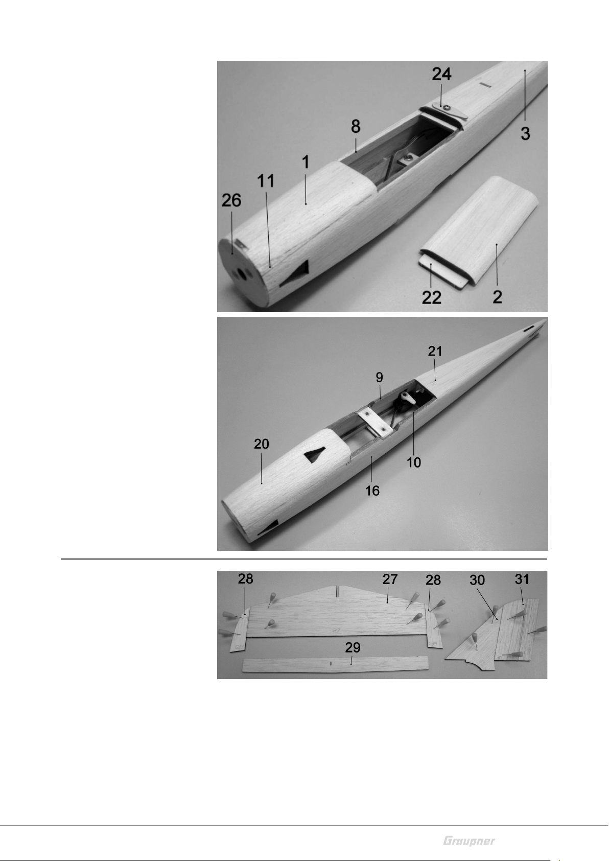
Assembly step 1
First mark a straight line in
the middle of the construction board, then cover the
construction board with
transparent film so that no
parts stick to it. Fasten the
fuselage bottom (1) and (3)
as well as the cover (2) congruently. Insert the cover (2)
loosely, do not glue it. Glue
the bulk (4) inclined by 2 °
forward using the angle template (52). This results in a
motor inclination of 2 °. Glue
the other bulks (5) to (7) ver-
tically.
Assembly step 2
Remove the cover (2). Chamfer the triangular strips (11)
at the back over a length of 2
cm, then glue them together
with the reinforcements (8)
and secure them. Make sure
that both reinforcements (8)
are exactly flush with the
outer edge of the fuselage
bottom parts (1) and (3).
Only when the adhesive has
dried out well, detach the
fuselage from the construction board and grind it sides
with the sanding block.
Assembly step 3
Glue the part (23), the hole
must match the one in the
fuselage bottom (3). Glue
the reinforcements (9) and
(10) with the triangular strips
(11) and secure them. Glue
the part (53). Press the nuts
(13) into the support (12)
and glue them with instant
glue. Make sure that no glue
penetrates the threads of
the nuts. Round off the outer
side edges of the support
(12) on the top, then glue in
the support. The rounded
edges are required so that
later the band (14) fits well.
4318_PN_V1
9 / 20
Page 10

Assembly step 4
After hardening the wood
glue, carefully remove the
fuselage from the construction board. Sand the outer
sides of the fuselage with
the sanding block (54) using
the coarse grained side. Do
not sand off the protruding
noses of part (53). Please
note that this sanding work
is carried out thoroughly,
this is very important for the
further construction and is
the prerequisite for an optimally shaped model fuselage.
Assembly step 5
Stick the polyester tape (14)
with superglue as shown in
the picture on the left. Apply
the super glue to the support (12) and reinforcements (9) and (10) before
stretching the polyester
tape. Please make sure that
this bonding process is carried out exclusively with
instant adhesive, as no other
adhesive ensures a sufficiently good bond between
polyester and plywood or
balsa wood. During the later
flight maneuvers the multiple fly forces of the model
weight must be absorbed by
the support (12).
10 / 20
4318_PN_V1
Page 11
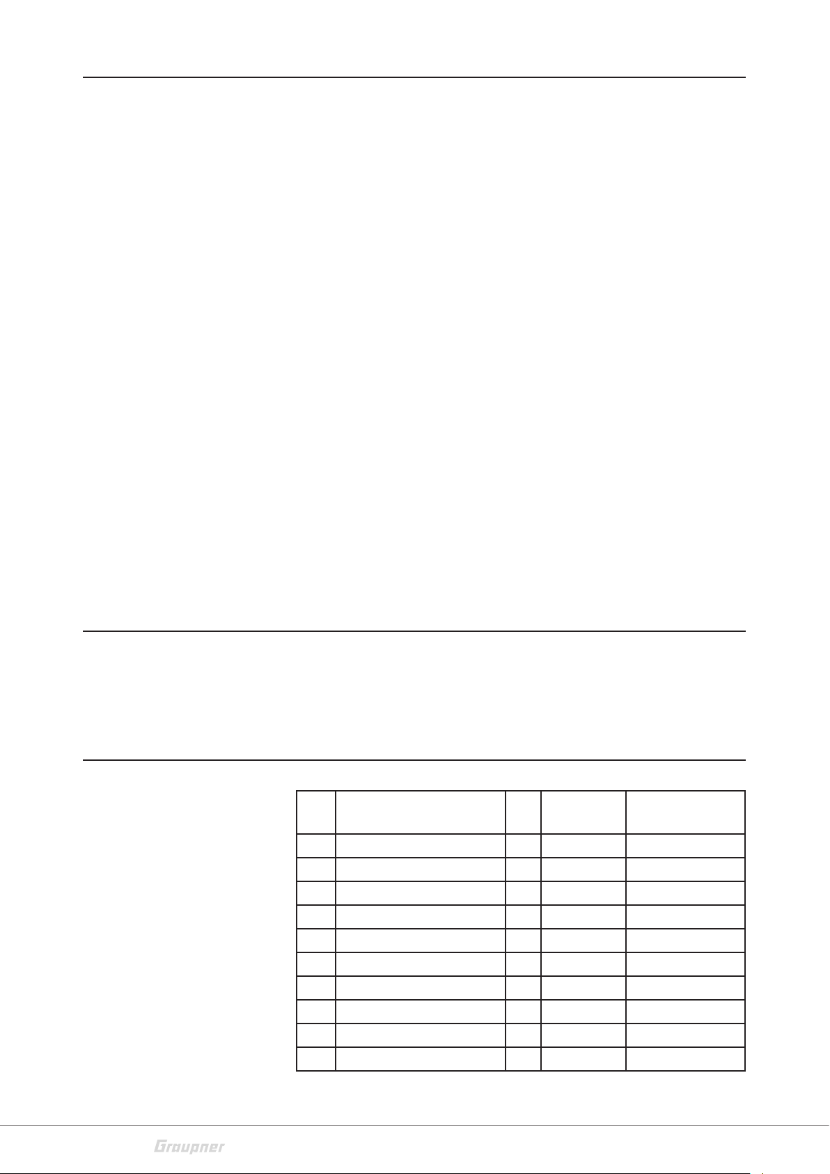
Assembly step 6
Cut off the ends of the polyester tape protruding below
and cut the tape over the
nuts (13). Try to install the
elevator servo from RC drive
set No. 4318.90 (No. 4318.90
is not included in the quickkit No. 4318). To do so, spare
the right-hand reinforcement (8) accordingly. This
process takes place only at
the present time, so that the
reinforcement (8) is rectilinear. The elevator servo can
already be fixed in the fuselage with a few drops of
instant glue. Make sure the
servo is flush with the outer
edge of the fuselage bottom.
Assembly step 7
Pin the fuselage back onto
the construction board with
fixing needles. Then glue
and fix the fuselage side
pieces (15) and (16). Make
absolutely sure that both
sides of the fuselage are
resting exactly on the construction board without any
gaps, and that super glue is
applied in the area of the
polyester tape (14). Insert
the pushrod outer tube (17)
and also glue in with the
instant adhesive.
Assembly step 8
Prepare the fuselage nose
cover (20) for further assembly. To do this, cut out the
field engraved in front with
the balsa cutter according to
the illustration. The recess
should be 5 mm deep, so
that later the motor leads
can have space. Sand the
end edge according to the
leading edge of the wing
4318_PN_V1
11 / 20
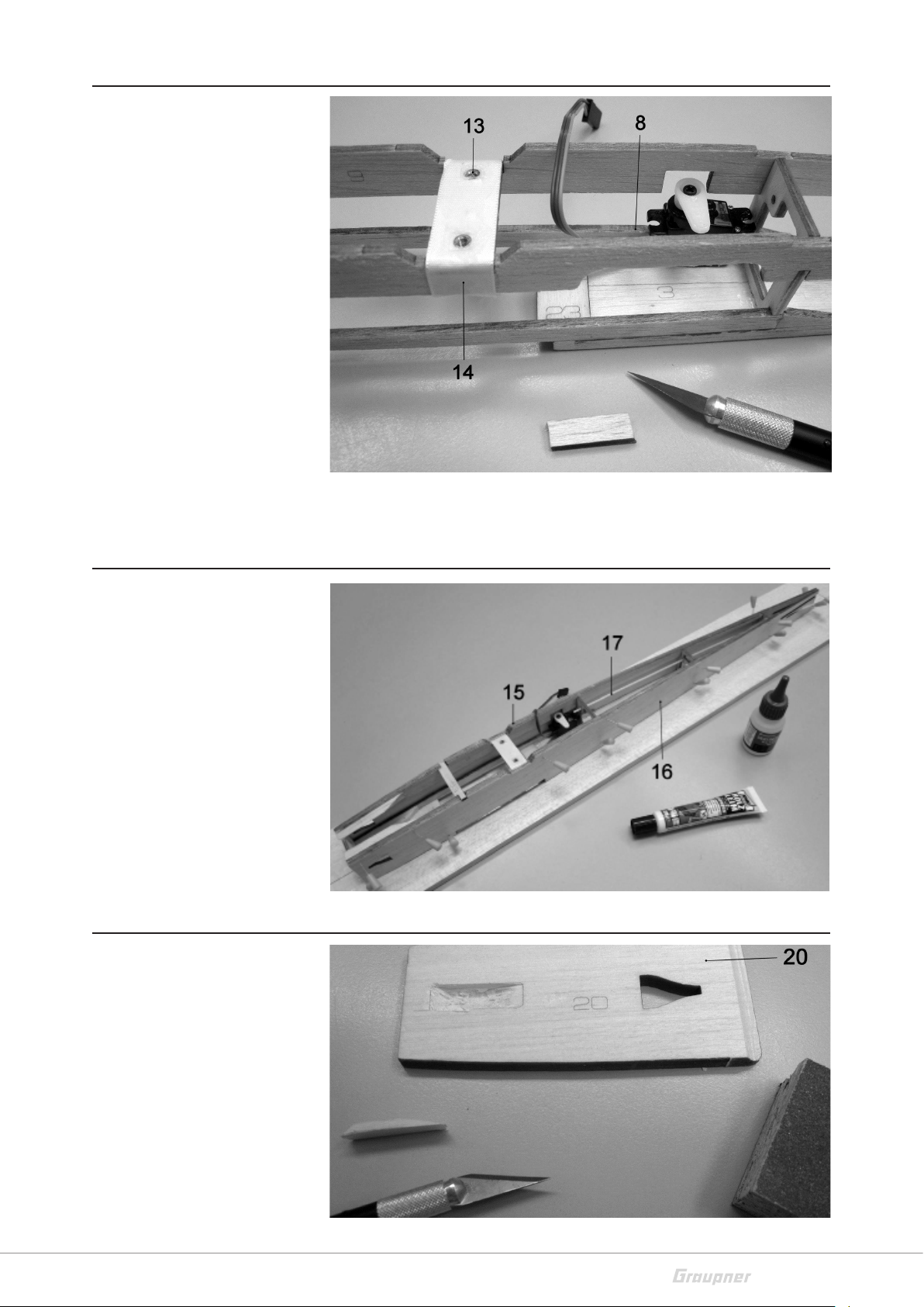
Page 12
(35) with the sanding block.
To check, attach the wing to
the building board as shown
in the figure and place part
(20). Please note, the small
radius is on the underside of
the wing, the top is profiled
to a depth of about 15 mm
finished with a large radius.
Assembly step 9
Thoroughly sand the top of
the fuselage with the sanding block (54), then glue on
the hull covers (20) and (21)
and secure them. Make
absolutely sure that the elevator support cover (21) is
glued exactly in the middle,
because otherwise later the
rudder sits off-center or
diagonally. Glue the parts
(19) and (22) onto the
engraved fields of the cover
(2).
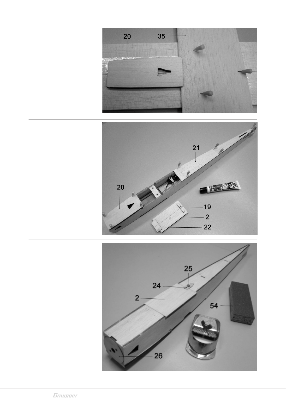
Assembly step 10
Insert the cover (2), screw
on the cap (24) with the
screw (25). Sand the front of
the fuselage and glue on the
front cover (26), use instant
adhesive; with wood glue
the thin plywood would
bend. Now give the hull its
shape by refining its aerodynamic shape.
12 / 20
4318_PN_V1
Page 13
The disc (26) serves as a
template. First round off the
fuselage edges with the
balsa plane, then with the
coarse-grained side of the
sanding block (54).
Make sure that the left and
right sides are evenly
rounded by removing the
cover (2). Lower the holes in
the bulkhead (4) and (26) for
the screws (18).
The figure on the left shows
the finished and sanded
upper side of the fuselage.
Please note that there is still
3 mm contact surface at the
tail end for the rudder. In the
area of the wing support,
grind the fuselage so far that
the upper edge of the fuselage side parts (15) and (16)
is only approx. 0.5 mm wide.
If the fuselage is optimally
shaped this has two positive
effects, on the one hand it
has a low air resistance and
on the other hand, the fuselage weight is reduced significantly. The fuselage
retains its good stability even
when rounded.
Assembly step 11
Glue and fix the tail parts as
shown. Bevel the front edge
of the elevator (29) at the
bottom by about 30 °, making sure that the slot for the
rudder horn (33) is on the
left side.
Round the front edges of
rudder and elevator using
the grinding block, not the
end edges.
4318_PN_V1
13 / 20
Page 14

Assembly step 12
Insert the prepared tail units
into the fuselage and align
them exactly, place the wing
(35) on the fuselage for control, sight from the front
whether the rudder is vertical and the elevator is parallel to the wing. If necessary,
check with a triangle ruler
placed on the wing. If all is
correct, as shown, apply a
few super glue in all corners
between the fuselage and
tail. The assembly of the
fuselage is complete.
Assembly step 13
Glue the reinforcement (36)
to the end edge of the wing
(35). Fix the strip (36) from
below with adhesive tape on
the wing without gaps. Then
tilt the bar slightly downwards and apply super glue
from the top, close it again
and immediately wipe off
the excess adhesive. Mark
the center line on the top
and bottom with a soft pencil, never press down firmly.
Assembly step 14
Place the wing centered on
the fuselage and align it at
right angles by means of a
square triangle. Then fix the
wing from the top with four
fixing needles. Open the flap
(2) and screw in the screws
(50) from below until they
impress a mark on the wing.
Remove the wing and
unscrew the screws (50).
14 / 20
4318_PN_V1
Page 15

Assembly step 15
Bevel the leading edge of
the reinforcement (41)
before sticking.
Then stick together with the
holes in the wing (35).
Check that the end edge is
parallel to the wing leading
edge and check the triangle
ruler.
Lower the holes for the screws (50) so that the screw heads do not protrude.
Assembly step 16
Cut off the end strips (38/39)
and glue them on, the underside should rest flat.
Then align the end strips
(39) to the contour of the
winglets.
Sand the top of the wing using the fine-grained side of the sanding block (54).
Assembly step 17
Glue the winglets (37) to the
wing by firmly attaching the
wing to the building board.
Loosely insert the ailerons
(40).
The V-shape of the winglets is 15 ° corresponding to 35 mm, measured at the end of the wing. When
the wood glue has hardened, sand the wing using the fine-grained side of the sanding block (54).
Assembly step 18
Glue the servo covers (42)
and (45) together and glue
them to the fastening straps
with a few instant glue.
Cover the servo housing
with adhesive tape so that it
will not be damaged when
sanding the balsa wood
parts. Unscrew the servo
lever. Streamline and sand
the panels.
Assembly step 19
Chamfer part (47) at the
back and glue on, put on
part (46) only loosely, as well
as the covered servos, mark
the contour of (45) on part
(46), saw it off, match the
front edge and stick on the parts (45) for part (46) below, then glue the servos.
4318_PN_V1
15 / 20
Page 16

Assembly step 20
The illustration shows the
fully installed aileron servos.
Insert the slots for the rudder horns (33) with the balsa
cutter into the ailerons (40).
Cut off the aileron linkage
(rest part of (32)) and trim
off with a pair of flat nose pliers at the end, first push on
the reinforcement (44) and
glue with superglue. Connect the ailerons to the wing
with hinge strap (49) (not
included). The assembly of
the wing is complete.
Assembly step 21
These parts of motor set No.
4318.90 are not needed, disassemble or remove. Note
that the motor set no.
4318.90 is not included in
the quick pack
No. 4318, it must be purchased separately as an accessory.
Assembly step 22
Install the CAM FOLDING
PROP according to instructions from No. 4318.90.
Insert the motor into the
fuselage and tighten with
the screws (18). The insertion of the motor is facilitated if an approximately 2
mm thick guide pin is
inserted from the front
through a hole in the associated mounting hole.
Assembly step 23
Lay the motor power line in
the fuselage as shown in the
picture, fix the speed controller and the power lines
to the fuselage wall with a
few superglue. Make sure
that the motor power lines
do not come into contact
with the rotating motor
housing.
16 / 20
4318_PN_V1
Page 17

Glue the rudder horn (33) in
the elevator (29), hook the
cranked end of the elevator
pushrod (32) into the rudder
horn, connect the elevator
(29) with hinged band to the
elevator.
Unhook the elevator pushrod at the front and attach it to the servo lever.
Assembly step 24
Mount the wing onto the
fuselage with the screws
(50). Install and tighten the
propeller. Connect the GR-12
HoTT receiver and insert it
behind the bulkhead (5).
Check all control functions
and bring all control surfaces
into neutral position. The
maximum control surface
excursions are 10 mm at the
aileron and 8 mm at the elevator, measured at the end
edge of the surface. I
t is not indispensable to
paint the model.
To protect the model against moisture, it can be painted 1 to 2 times with GLATTFIX pore filler. Before
and after the painting sand the surface with sanding paper No. 700.1.
Assembly step 25
Insert the battery as shown,
then balance the model. The
weighing takes place in ready
to fly state, ie with mounted
wing. The center of gravity is
measured at 50 mm from
the wing front edge. The
center of gravity is checked
by sustaining the model with
two fingers
at the center of gravity below the wing. The model should then be balanced and levelled. If necessary, move the battery.
Assembly step 26
Remove the individual writings (51) from the carrier foil and stick it to the desired position of the
model. The image on the packaging carton serves as a template. Paint the canopy with a black fiber
pen. Fly the model with neutral control surfaces in calm or light wind. An obstacle-free meadow is
ideally suited as a terrain. Start the model into the air by hand against the wind direction.
GRAUPNER Modellbau wishes many beautiful flights with the PEP model
4318_PN_V1
17 / 20
Page 18

Symbol description
!
!
!
Always observe the information indicated by this warning sign. Par-
ticularly those which are additionally marked with the words CAUTION or WARNING. The signal word WARNING indicates the
potential for serious injury, the signal word CAUTION indicates possibility of lighter injuries.
The signal word Note indicates potential malfunctions.
Attention indicates potential damages to objects.
Safety notes
General
These safety instructions are intended not only to protect your own
and other people’s safety, but also to protect the product. Therefore
please read this section very carefully before using the product!
Do not leave the packaging material lying around, this could be
a dangerous toy for children.
Persons, including children, with reduced physical, sensory or
mental capabilities, or lack of experience or knowledge, or not
capable to use safely the transmitter must not use the transmitter without supervision or instruction by a responsible person.
Operation and use of radio-controlled models needs to be learnt!
If you have never driven such a model, then start extra carefully
and make sure to be familiar with the reactions of the model to
the remote control commands. Proceed always responsibly. This
also means that you have for your own protection liability insurance.
Protect all equipment from dust, dirt, moisture. All equipment
must be protected from vibration as well as excessive heat or
cold. The models may only be operated remotely in normal outside temperatures such as from -10°C to +55°C.
For your safety by handling the transmitter
WARNING
Also while programming the transmitter, make sure that a connected motor cannot accidentally start. Disconnect the fuel supply or drive battery beforehand.
18 / 20
4318_PN_V1
Page 19

Package content
P
Care and maintenance
• Clear construction manual in German with detailed views.
• English, French and Italian manuals available for download.
• Laser cut boards made of balsa wood and plywood.
• Profile sawn end strips and ailerons made of balsa wood.
• Bowden cable pushrods for elevator.
• Fasteners for motor and wing.
• Decals with stamped lettering.
• Ready-to-use sanding block.
Notes on care
The product does not need any maintenance, it works so as it is without any special care. In your own interest please protect the model
from dust, dirty and humidity!
Warranty conditions
Graupner/SJ, Henriettenstrassee 96, 73230 Kirchheim/Teck grants
from the date of purchase of this product for a period of 24 months.
The warranty applies only to the material or operational defects
already existing when you purchased the item. Damage due to misuse, wear, overloading, incorrect accessories or improper handling
are excluded from the guarantee. The legal rights and claims are not
affected by this guarantee. Please check exactly defects before a
claim or send the product, because we have to ask you to pay shipping costs if the item is free from defects.
The present construction or user manual is for informational purposes only and may be changed without prior notice. The current
version can be found on the Internet at www.graupner.de on the relevant product page. In addition, the company
responsibility or liability for any errors or inaccuracies that may
appear in construction or operation manuals.
Not liable for printing errors.
Graupner/SJ has no
4318_PN_V1
19 / 20
Page 20

 Loading...