

Page 1
Manual
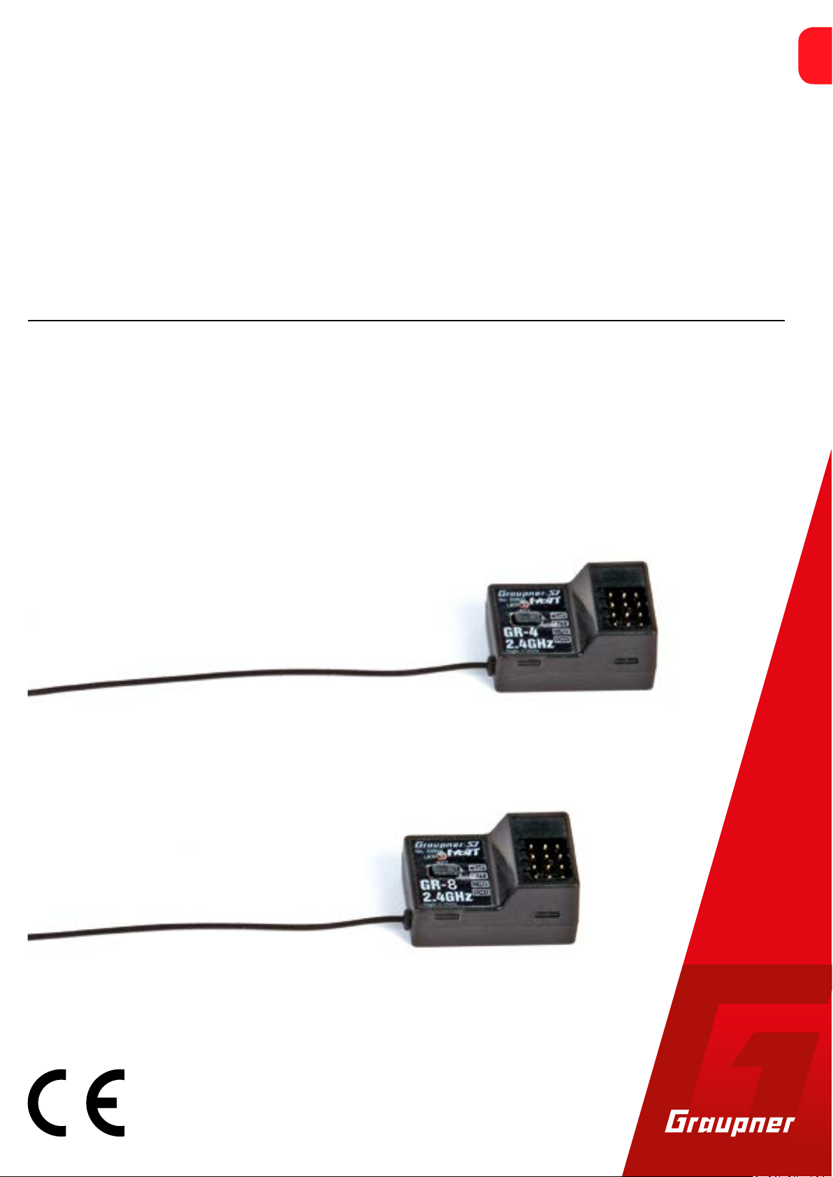
GR-4 HoTT and GR-8 HoTT V2
2 channel HoTT and 4 channel HoTT V2 receiver
No. 33502
No. 33504
EN
Copyright © Graupner/SJ GmbH
Page 2

Index
Introduction ......................................................................................4
Service centre ...................................................................................4
Intended use ....................................................................................5
Target group ....................................................................................5
Package content ................................................................................5
Technical data ...................................................................................6
accessories ......................................................................................6
Symbol description ...........................................................................6
Safety notes ......................................................................................7
For your safety by handling the transmitter and the receiver .......7
For your safety by handling the batteries ......................................8
Installing the receiver .....................................................................10
Connection assignment ................................................................10
Receiver GR-4 HoTT ...................................................................10
Receiver GR-8 HoTT V2 .............................................................10
Receiver binding ...........................................................................12
Receiver reset ...............................................................................13
"Telemetry" menu ..........................................................................14
SETTING & DATA VIEW ..................................................................14
Receiver GR-4 HoTT ...................................................................14
Receiver GR-8 HoTT V2 .............................................................15
Connection example .......................................................................18
… for electric driven models .........................................................18
… for model with I.C. engine .........................................................18
Firmware update ............................................................................20
SIMPLIFIED DECLARATION OF CONFORMITY ................................22
Manufacturer ................................................................................22
Notes on environmental protection ..............................................23
Care and maintenance ...................................................................23
Warranty conditions .......................................................................23
2 / 24 3 / 24
33502_33504_GR-4_GR-8_DE_V1sh 33502_33504_GR-4_GR-8_DE_V1sh
Page 3
Introduction
Intended use
Thank you very much for purchasing a Graupner GR-4 HoTT or GR-8
HoTT V2 receiver.
Read this manual carefully to achieve the best results with your
transmitter system and first of all to safely control your models. If
you experience any trouble during operation, take the instructions
to help or ask your dealer or Graupner Service Centre.
Due to technical changes, the information may be changed in this
manual without prior notice. Be always updated by checking periodically on our website, www.graupner.de to be always uptodate with
the products and firmwares.
This product complies with national and European legal requirements.
To maintain this condition and to ensure safe operation, you must
read and follow this user manual and all the safety notes before
using the product and you have to respect those notes also for future
use!
Note
This manual is part of that product. It contains important information concerning operation and handling. Keep these instructions for
future reference and give it to third person in case you gave the
product.
The receiver only be used for the purpose specified by the manufacturer for operation of remote controlled models without passengers. This includes all types of UAVs or all types of unmanned aerial
vehicles as well as all types of unmanned land and water vehicles.
Any other type of use is impermissible and may cause significant
property damage and/or personal injury. No warranty or liability is
therefore offered for any improper use not covered by these provisions.
In addition, it is explicitly pointed out that you must inform yourself
about the laws and regulations applicable at your respective starting
point before starting the remote control operation. Such conditions
may differ from state to state, but this must be followed in every
case.
Read through this entire manual before you attempt to install or use
the receiver.
Note
The GR-8 HoTT V2 receiver can only be bound to transmitters that
control the HoTT V2 transmission protocol. This receiver is not suitable for operation with "normal" HoTT transmitters. Suitable transmitters are currently only the Graupner transmitters X-8N and X-8E.
Service centre
Graupner Central Service
Graupner GmbH
Henriettenstrasse 96
D-73230 Kirchheim / Teck
Graupner USA
3941 Park Dr Suite 20-571
El Dorado Hills, CA 95762
Graupner in Internet For the service centers outside Germany please refer to our web site
www.graupner.de.
Servicehotline
(+49) (0)7021/722-130
Monday - Thursday:
9:15 am - 4:00 pm
Friday:
9:15 am - 1:00 pm
service@graupner.de
Website: www.graupnerusa.com
Phone: +1 855-572-4746
Email:service@graupnerusa.com
Target group
The item is not a toy. It is not suitable for children under 14. The
installation and operation of the receiver must be performed by
experienced modellers. If you do not have sufficient knowledge
about dealing with radio-controlled models, please contact an experienced modeller or a model club.
Package content
• Receiver GR-4 HoTT or GR-8 HoTT V2
• Manual
Note
Graupner/SJ works continuously to the further development of the
products. We must therefore reserve the right to change the scope
of delivery in terms of form, technology and equipment.
4 / 24 5 / 24
33502_33504_GR-4_GR-8_DE_V1sh 33502_33504_GR-4_GR-8_DE_V1sh
Page 4
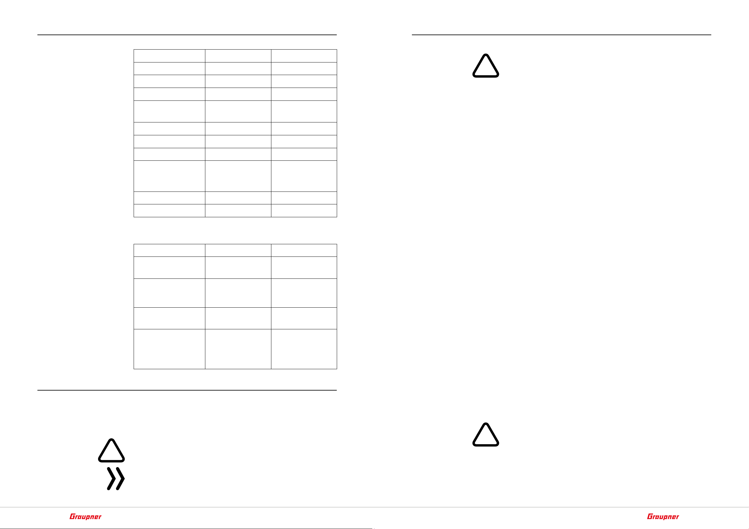
Technical data
!
!
!
Safety notes
accessories
GR-4 HoTT GR-8 HoTT V2
Operating voltage
Frequency 2,4 GHz 2,4 GHz
Modulation FHSS FHSS
Transmission protocol
Control functions 2 4
Power consumption
Temperature range
Antenna length 1x 145 mm,
Dimensions
Weight 6 g 6 g
Transmitter Standard transmit-
Servo
ESC S3026.T S3051
ESC with WiFi S3078
3,6 … 8,4 V 3,6 … 8,4 V
HoTT HoTT V2
approx. 35 mA approx. 70 mA
-15 ... +70 °C -15 ... +70 °C
1x 145 mm,
of which the last
30 mm active
30 x 21 x 15 mm 30 x 21 x 15 mm
GR-4 HoTT GR-8 HoTT V2
ter
Standard servos S4086
of which the last
30 mm active
X-8E and X-8N
S4087
S4088
S3052
S3084
S3085
S3086
These safety instructions are intended not only to protect the product, but also for your own and other people’s safety. Therefore please
read this section very carefully before using the product!
• Do not leave the packaging material lying around, this could be a
dangerous toy for children.
• Persons, including children, with reduced physical, sensory or
mental capabilities, or lack of experience or knowledge, or not
capable to use safely the receiver must not use the receiver without supervision or instruction by a responsible person.
• Operation and use of radio-controlled models needs to be learnt!
If you have never driven such a model, then start extra carefully
and make sure to be familiar with the reactions of the model to
the remote control commands. Proceed responsibly.
• First, always perform a range and function test on the ground (to
do so, hold your model tight), before you use your model. Repeat
the test with running motor and with short throttle bursts.
• Only use the components and spare parts that we recommend.
Always use matching, original Graupner plug-in connections of
the same design and material.
• Make sure that all of the plug-in connections are tight. When disconnecting the plug-in connections, do not pull the cables.
• Protect the receiver from dust, dirt, moisture and foreign parts.
Do not expose it to vibrations or to extreme heath or cold. The
models may only be operated remotely in normal outside temperatures such as from -10°C to +55°C.
• Always use all your HoTT components only with the latest firmware version.
• Before you start using the remote control model, you have to
check the further relevant laws and regulations. These laws you
must obey in every case. Pay attention to the possibly different
laws of the countries.
• Due to safety and licensing reasons (CE), any reconstruction and/
or modification of the product is prohibited.
• If you have questions which cannot be answered by the operating manual, please contact us or another expert in the field.
Symbol description
Always observe the information indicated by these warning signs.
Particularly those which are additionally marked with the words
CAUTION or WARNING.
The signal word WARNING indicates the potential for serious injury,
the signal word CAUTION indicates possibility of lighter injuries.
The signal word Note indicates potential malfunctions.
Attention indicates potential damages to objects.
6 / 24 7 / 24
33502_33504_GR-4_GR-8_DE_V1sh 33502_33504_GR-4_GR-8_DE_V1sh
For your safety by handling the transmitter and the receiver
WARNING
Also while programming the transmitter, make sure that a connected motor cannot accidentally start. Disconnect the fuel supply or drive battery beforehand.
Avoid impacts and crushing. Check the receiver regularly for damages to the housings and cables, specially after model crashes.
Page 5

Damaged or wet receiver, even if re-dried, should no longer be
!
!
used!
CAUTION
Avoid every kind of short-circuit in all sockets of the transmitter!
Risk of fire! Use only the suitable connectors. In no case the electronic component of the transmitter or of the receiver may be
changed or modified. Due to licensing reasons, any reconstruction
and/or modification of the product is prohibited.
Note
During transport protect the model and the transmitter from damages.
For your safety by handling the batteries
CAUTION
• Protect the batteries from dust, dirt, moisture, heat and vibrations. Only use in dry locations.
• Do not use any damaged battery.
• Batteries may not be heated, burned, short-circuited.
• If handled improperly, there is a danger of fire, explosion, irritation and burns.
• Leaked electrolyte is caustic and should not be touched or
come into contact with your eyes. In case of emergency, rinse
with a large quantity of water and consult a Med. Doctor.
• Stock the batteries in dry and fresh conditions.
• Dispose of the battery in the proper disposal centers.
8 / 24 9 / 24
33502_33504_GR-4_GR-8_DE_V1sh 33502_33504_GR-4_GR-8_DE_V1sh
Page 6

Installing the receiver
B/T
/V
/V
Slots 1 and 2 or 1 to 4
Connection assignment
Receiver GR-4 HoTT
Receiver GR-8 HoTT V2
The receiver must be protected against dust, exhaust gases, splash
water, rests of oil etc. in the model. When you install your receiver,
make sure that it is not excessively airtight to prevent it from overheating during operation.
Servo cables may not be wound around antenna or run next to it.
Make sure that the cables cannot shift to lie directly adjacent to
antenna during flight.
In the case of carbon fibre chassis, at least the last 35 mm of the
antennas shall be routed outside.
The connection cables to be connected to the receiver must be
plugged with the black or brown cable outwards into the connector
strip of the receiver, see illustrations. The polarity of the plug-in system cannot be reversed. Do not apply force. Never connect the connecting cables "across", over 3 connections, to the receiver. This
immediately leads to a short circuit of the power supply; the destruction of any connected components as well as the immediate loss of
all warranty claims.
The GR-4 HoTT receiver has a total of 4 slots:
T
2
1
1 Steering servo
2 Throttle servo or ESC
B/T HoTT telemetry sensors / Power supply / Updates
T/V Temperature / voltage sensor
Note
The GR-4 HoTT receiver is compatible with all Graupner HoTT trans-
mitters.
The steering servo is to be connected to port 1 and the throttle servo
of combustion engine or the speed controller of electric models to
port 2.
Ports 3 and 4 of the GR-8 HoTT V2 are freely assignable control channels for special functions.
Both on the transmitter side and via the telemetry menu, see below,
each of the four ports of the GR-8 HoTT V2 receiver can be arbitrarily
switched to one of a total of six connection protocols, extending the
range of connectable RC components from standard servo to ultrashort pulse digital controlled speed controller.
The power supply of the receiver as well as the RC components can
be connected to it over each of these four connections.
Port "B/T"
Note
Only available with the GR-4 HoTT receiver.
This socket is suitable for connecting the receiver power supply as
well as for connecting HoTT telemetry sensors and for updating the
receiver.
The voltage applied to this socket operating voltage of the receiving
system is monitored. As soon as the warning threshold set in the line
"AL RX-V" of the receiver menu "RX SETUP" is exceeded, the transmitter emits an acoustic alarm.
Port "T/V"
This socket is only suitable for connection of the optional external
voltage and temperature sensor with the order no. S8362 and the
voltage measurement described below.
If a sensor is connected, the warning threshold set in the lines "AL
EX-V" or "AL EX-T" of the receiver menu "RX SETUP" becomes effective. As soon as this value is exceeded, the transmitter issues an
alarm.
The GR-8 HoTT V2 receiver has a total of 5 slots:
T
4
3
2
1
1 Steering servo
2 Throttle servo or ESC
3 free or battery or special function so as firmware updates
Attention
This socket is neither suitable for connecting a receiver power supply nor for the direct connection of a drive battery! As a result, the
receiver would be destroyed immediately. The socket is only suitable for connecting the mentioned sensors or for measuring the
voltage of a battery according to the following scheme:
4 free or battery or special function
T/V Temperature / voltage sensor
Note
the GR-8 HoTT V2 receiver is actually only compatible with the
Graupner transmitters X-8E and X-8N.
10 / 24 11 / 24
33502_33504_GR-4_GR-8_DE_V1sh 33502_33504_GR-4_GR-8_DE_V1sh
Page 7

s + –
100 mm
Receiver binding
–
max. 25,5 V =
50 mm
100nF
2k7Ω
22kΩ
+
To establish a connection with the transmitter, the Graupner HoTT
receiver must first be "bound" to at least one model memory in "its"
Graupner HoTT transmitter. This process is generally called "binding". However, the methods to be used are not always the same, so
the following step-by-step instructions apply only to binding a GR-4
HoTT or GR-8 HoTT V2 receiver to any transmitter:
Binding step-by-step
1. Prepare the transmitter or model memory to be bound according
to the instructions for binding.
2. Eventually, switch on the receiver power supply.
The LED of the GR-4 HoTT or GR-8 HoTT V2 receiver blinks in red.
3. Press the SET button on the receiver until the receiver LED flashes
red / green.
‖ The receiver is for the following 3 seconds in Binding mode.
4. Within this approximately 3 seconds start the transmitter-side
binding according to the instructions of the transmitter.
Receiver reset
To reset the receiver, press and hold its SET button while turning on
the power to the receiver:
If the reset has been triggered with the transmitter switched off or
with an unbound receiver, the red LED shortly lights up before the
green LED lights up and the red LED flashes 2 times in parallel. Then
both LEDs go off before only the red LED continues to flash. Release
the button once the LEDs go dark.
If the reset is performed with a not bound receiver, you can then
start a binding process at any time.
If a reset has already been carried out on an already-bound receiver
and the associated model memory is active in the switched-on transmitter, the green LED of the receiver should light steadily after
approx. 2 to 3 seconds and thus signal a correct connection to the
transmitter. Otherwise the process has to be repeated.
Notes
• Through a RESET ALL of the settings in the receiver are brought
to the factory settings with the exception of the HoTT synchronization information!
• If a reset is performed accidentally, all of these settings that
were made using the "Telemetry" menu in the receiver should
be restored.
• Resetting is particularly recommendable when you want to
switch a receiver to a different model. This makes it easy to keep
settings which do not match from being transferred.
If the green LED of the receiver GR-4 HoTT or GR-8 HoTT V2 turns
solid green after a few seconds and the transmitter signals a correct
connection according to his instructions, the binding process has
been successfully completed. The transmitter/receiver combination
is ready for operation.
If the LED of the receiver GR-4 HoTT or GR-8 HoTT V2 flashes red
again and the transmitter signals a missing connection, the "Binding"
has failed. Possibly, change the positions of the devices involved and
repeat the entire procedure.
12 / 24 13 / 24
33502_33504_GR-4_GR-8_DE_V1sh 33502_33504_GR-4_GR-8_DE_V1sh
Page 8

"Telemetry" menu
Receiver GR-8 HoTT V2
SETTING & DATA VIEW
Receiver GR-4 HoTT
RECEIVER 0.09
AL RX-V( 5.1V): 3.7V
AL RX-T(+31°C): 65°C
PERIOD : 20ms
AL EX-V( 0:0V): AUTO
AL EX-T( --°C):100°C
The basic handling of the "Telemetry" menu is described in the
respective transmitter instructions or the instructions of the SmartBox. By way of derogation, only in certain receivers the menu struc-
ture is summarized under the generic term "setting & data view".
These instructions also provide information on how to access this
menu. Change accordingly to the first setting page of the receiver to
set up.
Note
The setting values shown in the following display illustrations always
show the standard values.
The GR-4 HoTT receiver has only one display page. In it, if necessary,
some warning thresholds can be adjusted:
Value Alarm threshold Adjustment
range
AL RX-V Receiver power supply 3.5 … 8.0 V
AL RX-T Receiver temperature 30 … 80 °C
RX DATA VIEW >
S-QUA : 99%
S-STR : 100%
S-dBm : -31dBm
RX-TEMP : +38°C
LOSS PACK : 6ms
BATT VOLT : 5.5V
LOW VOLT : 5.5V
RX DATA VIEW
In this display page of the submenu "SETTING & DATA VIEW" you will
not be able to make any settings. This page is for information only:
Value Description
S-QUA Quality expressed as a percentage of the signal
packages from the transmitter arriving at the
receiver
S-STR Signal strength expressed in percentage of the
signal from the transmitter arriving at the receiver
S-dBm Level in dBm expressed as the percentage of
the transmitter signal arriving at the receiver
RX-TEMP Receiver temperature in °C
LOSS PACK Shows the longest time in milliseconds in which
data packages were lost when transmitting from
the transmitter to receiver
BATT VOLT Current operating voltage of the receiver
LOW VOLT Current operating voltage of the receiver since the
last time the receiver was turned on
PERIOD None 10 or 20 ms
AL EX-V external voltage sensor to port
AUTO / 2 … 24 V
"T/V"
AL EX-T external temperature sensor to
50 … 150 °C
port "T/V"
Notes
• If your system is used exclusively with digital servos, you can set
a cycle time (frame rate) of 10 ms in the value field of the line
"PERIOD". If your system includes some or uses exclusively analogue servos, always select 20 ms since the analogue servos may
be overloaded and respond by "jittering" or "growling".
• The values shown in parentheses are the actual operating data
transmitted by the receiver via return channel.
RX SETUP V2.00 <>
>AL RX-V( 5.5V): 3.7V
AL RX-T(+40°C): 65°C
AL EX-V( 0.0V): AUTO
AL EX-T( --°C):100°C
LANGUAGE : german
RX SETUP
In this display, some warning thresholds may be adjusted. It have the
following meanings:
Value Alarm threshold Adjustment
range
AL RX-V Receiver power supply 3.5 … 8.0 V
AL RX-T Receiver temperature 30 … 80 °C
AL EX-V external voltage sensor to port
"T/V"
AL EX-T external temperature sensor to
port "T/V"
LANGUAGE Language france
Note
The values shown in parentheses are the actual operating data
transmitted by the receiver via return channel.
AUTO / 2 … 24 V
50 … 200 °C
german
english
14 / 24 15 / 24
33502_33504_GR-4_GR-8_DE_V1sh 33502_33504_GR-4_GR-8_DE_V1sh
Page 9

CH FUNCTION
FAIL SAFE
CH FUNCTION <>
>CH1 NSR12m0 1500µs
CH2 NSR12m0 1500µs
CH3 NSR12m0 1500µs
CH4 NSR12m0 1500µs
LOSS PACK : 6ms
BATT VOLT : 5.5V
*NORMAL SIGNAL 12.0ms
DEVICE LIST VIEW <>
No Device Ch Port
>00 RECEIVER -- - 01 --------- -- - 02 CAR ESC-- 02 02
03 --------- -- - 04 --------- -- - 05 --------- -- --
In this display, it may be necessary to adapt the connection protocols
at the four receiver connections to the properties of the respectively
connected RC components. The information given by the manufacturer of the respective RC component must be observed !!!
The following selections are available for each control channel:
• USR3m0 0 : ULTRA SIGNAL 3.0 msec
• digital "Ultra" protocol with a pulse sequence of 3.0 msec
• FSR3m00 : FAST SIGNAL 3.0 msec
• digital "Fast" protocol with a pulse sequence of 3.0 msec
• SUMD-V2 : FAST SIGNAL BUS 3.0 msec
• digital BUS signal with a pulse sequence of 3.0 msec
• NSR6m00 : NORMAL SIGNAL 6.0 msec
• "Normal" analogue control signal with ultra-short pulse sequence
• NSR12m0 : NORMAL SIGNAL 12.0 msec
• "Normal" analogue control signal, suitable for digital servos
• NSR24m0 : NORMAL SIGNAL 24.0 msec
• "Normal" analogue control signal, suitable for standard servos
In principle, these protocols can be selected or set per control channel both in this menu and according to the respective transmitter
instructions in a transmitter-side menu.
Attention
In both cases, however, changes made will only take effect after a
restart of both the receiver and the sender in the following order.
Restart step by step
1. Switch the receiver off.
2. Switch the transmitter off.
3. Switch the transmitter on.
4. Switch the receiver on.
DEVICE LIST VIEW
If at least one channel has been changed to "SUMD V2" in the "CH
FUNCTION" display described above and suitable RC components
are connected to it before the receiver is switched on again, these
components are displayed in this list.
FAIL SAFE <
>F/S MEMORY: NEIN
F/S DELAY : 100ms
CH1(STR):HOLD
CH2(THR):HOLD
CH3(AUX):HOLD
CH4(AUX):HOLD
05 --------- -- --
The simpler and recommended way to fail-safe settings is to use the
transmitter's Fail Safe menu.
Similar, albeit more cumbersome, is the "FAIL SAFE" option described
below.
In both cases, these settings determine the behaviour of the receiver
in the event of interference with the transmission from the transmitter to the receiver.
• F/S MEMORY
After switching to "YES" and confirming it, save the current servo
positions in the receiver.
• F/S DELAY
This line specifies how long the receiver is going to keep the RC
components connected to it, after the connection has been terminated, at their most recently received positions before forwarding the previously stored fail-safe positions to the connected
components. This setting is adopted by all the channels and only
affects the servos programmed for "F/S" mode.
Adjustment range: 50, 100, 250, 500, 750 ms and 1,0 second
• CH1 … CH4
The factory setting for four channels is "HOLD".
Each selected channel (servo connector of the receiver) can be
set to:
• F/S
With this selection, the corresponding servo moves into the
position displayed in µs in the line "POSITION" in case of a
malfunction after expiration of the delay set in the right-hand
line for the remainder of the malfunction.
1500 µs corresponds to the neutral position
• HOLD
With the "HOLD" setting, over the course of a malfunction,
the servo remains in the last correctly received servo position.
• FREE
With a setting of "FREE", the receiver sets the transmission of
(buffered) control pulses for the relevant servo output for the
duration of the fault in the event of a fault. The receiver
switches off of the pulse line in a manner of speaking.
Attention
Analogue servos and many digital servos no longer experience resistance to the ongoing control pressure after control
pulses stop and are moved out of their position at higher or
lower speed.
16 / 24 17 / 24
33502_33504_GR-4_GR-8_DE_V1sh 33502_33504_GR-4_GR-8_DE_V1sh
Page 10

Connection example
red wire of the voltage sensor
Aach temperature
sensor to cylinder head
… for electric driven models
E.S.C.
Temp. /
Receiver
voltage
sensor
CH 4
CH 3
CH 2
Baery connecon
Motor connecon
ON/OFF switch
Temperature sensor
Steering servo
… for model with I.C. engine
Temp. /
voltage
Sensor
Receiver
Baery
CH 2
CH 1
CH 1
Throle servo
Steering servo
Receiver power supply
18 / 24 19 / 24
33502_33504_GR-4_GR-8_DE_V1sh 33502_33504_GR-4_GR-8_DE_V1sh
Page 11

Firmware update
Updates to the receiver’s firmware are made via the receiver connection 3 using a PC running Windows 7 ... 10. You will also need a
USB interface, No. 7168.6, and adapter lead, No. 7168.S, which are
available separately.
The programs and files required can be found in the Download area
for the corresponding products at www.graupner.de.
Connect the adapter lead to the USB interface. The polarity of the
plug-in system cannot be reversed. Note the small chamfers on the
sides. Do not use force, the plug should click into place easily.
Plug the other end of the adapter cable into the GR-4 HoTT receiver
in the port marked with "B/T" and in the GR-8 HoTT V2 receiver into
the "3 + -" socket. The polarity of the plug-in system cannot be
reversed. Do not apply force. The plug should be pushed all the way
in with the black or brown wire facing outside the receiver.
The update is carried out via the "HoTT device" program section of
the program "Firmware_Upgrade_gr_Studio". Please follow the
notes of the software. The further procedure is also described in
detail in the manual contained in the data package. You can also
download these from the download page of the product at
www.graupner.de.
20 / 24 21 / 24
33502_33504_GR-4_GR-8_DE_V1sh 33502_33504_GR-4_GR-8_DE_V1sh
Page 12

P
SIMPLIFIED DECLARATION OF CONFORMITY
Graupner/SJ hereby declares that the radio system 33502 GR-4
HoTT and 33504 GR-8 HoTT V2 comply with the Directive 2014/53/
EU.
The full text of the EU Declaration of Conformity is available at the
following Internet address: www.graupner.de
Manufacturer
Graupner Co., Ltd
Post Code: 14557
Notes on environmental protection
If this symbol is on the product, instructions for use or packaging, it
indicates that the product may not be disposed with normal household waste once it has reached the end of its service life. It must be
turned over to a recycling collection point for electric and electronic
apparatus.
Individual markings indicate which materials can be recycled. You
make an important contribution to protection of the environment by
utilizing facilities for reuse, material recycling or other means of
exploiting obsolete equipment.
Batteries must be removed from the unit and disposed of separately
at an appropriate collection point. Please inquire if necessary from
the local authority for the appropriate disposal site.
8th F, 202 Dong, Chunui Techno-Park II, 18, 198 Street
Bucheon-ro, Wonmi-Gu, Bucheon-Shi, Gyeonggi-do
South Korea
Care and maintenance
The product does not need any maintenance. Always protect it
against dust, dirt and moisture.
Clean the product only with a dry cloth (do not use detergent!) lightly
rub.
Warranty conditions
Graupner/SJ GmbH, Henriettenstrassee 96, 73230 Kirchheim/Teck
grants from the date of purchase of this product for a period of 24
months. The warranty applies only to the material or operational
defects already existing when you purchased the item. Damage due
to misuse, wear, overloading, incorrect accessories or improper handling are excluded from the guarantee. The legal rights and claims
are not affected by this guarantee. Please check exactly defects
before a claim or send the product, because we have to ask you to
pay shipping costs if the item is free from defects.
These operating instruction are exclusively for information purposes
and are subject to change without prior notification. The current
version can be found on the Internet at www.graupner.de on the
relevant product page. In addition, the company Graupner/SJ has
no responsibility or liability for any errors or inaccuracies that may
appear in construction or operation manuals.
Not liable for printing errors.
22 / 24 23 / 24
33502_33504_GR-4_GR-8_DE_V1sh 33502_33504_GR-4_GR-8_DE_V1sh
Page 13

 Loading...