

Page 1

Náv od V1.0
Neručím e za tiskové chyby! Zm ěny vyhrazeny !
We are not responsible for any printing bugs! Modications reserved!
Revize: D ecember 2013
PŘIJÍMAČ GR-18 3xG+3A+Vario & GR-24PRO 3xG+3A+3M+Vario
RECEIVER GR-18 3xG+3A+Vario & GR-24PRO 3xG+3A+3M+Vario
NÁVOD K POUŽITÍ
MANUAL
Obj. číslo: 33579
Order No: 33579
www.modellmarkt24.ch; www.modellmarkt24.de
Obj. číslo: 33583
Order No: 33583
Page 2

CHAPTER PAGE
Safety Notes
1
Functions
2
2.1. Binding
2.1.1. Binding Multiple Receivers
2.2. Fail-Safe Function
2.3. Range-checking
2.4. Installation in the model (airplane)
2.5. Installation in the model (heli)
Receiver
3
3.1. Connections
3.2. Receive r set-up menu
3.3. Free mixe rs
3.4. Assignin g the gyro axes
3.5. Adjust S ervolimit for chann els
Programming the gyro settings
4
4.1. Programming PID correction
4.2. Program ming the factors
4.2.1. Programming, transmi tter with proporti onal controls
4.2.2. Programming, transmitter without proportional controls
4.3. Initialising the gyro
Firmware Update
5
Declaration of Conformity
6
Manufacturer’s declaration
7
Environmental protection notes
8
Warranty
CONTENTS
39
42
42
43
43
44
45
46
47
47
48
51
56
60
60
61
63
63
64
65
66
70
71
72
73
37
Page 3

Thank you for purchasing the Graupner HoTT 2.4 System Please read through
this entire manual before you attempt the installation
and usage of your Graupner HoTT 2.4 System!
These operating instructions are part of this product. They contains important notes to the operation and handling. Please
take this into consideration when you pass on the product to third parties. Neglect of the operating instructions and the safety
instructions lead to expiring the warranty. Graupner constantly work on the advancement of all remote control systems;
changes of the s cope of delive ry in form, te chnology an d equipment we m ust reserve o urselves the refore. Please h ave understan ding
for the fact that from data and illustrations of this operating instructions no requirements can be derived.
Please keep the se instructions for fur ther reference!
APPROVED USAGE
The receiver is intended exclusively for use in radio -controlled models. Any other usage is prohibited, and may result in
damage to the receiver or model, and serious personal injury. We grant no guarantee and accept no liability for any t ype
of use outside the stipulated range.
Not suitable for children under fourteen years. This receiver is not a toy!
The receiver is also equipped with a telemetry function which is only available in combination with a Graupner/SJ HoTT
2.4 system. If you do not own a Graupner/SJ HoTT 2.4 system, the receiver will not work.
Please start by reading through the whole instructions before you attempt to install and operate the receiver.
38
Page 4
These operating instructions are an integral part of the product. They contain important notes on operating and handling
the receiver. For this reason please store the operating instructions in a safe place, and pass them on to the new owner
if you ever dispose of the product. Failure to observe the operating instructions and safet y notes invalidates
the guarantee.
Here at Graupner we are constantly working on the fur ther development of all our products; for this reason we are obliged
to reserve the right to introduce changes to the set contents in form, technology and features.
Please understand that we will not countenance claims resulting from information and illustrations in these operating
instructions.
Please store the operating instructions in a safe place for future reference!
1. SAFETY NOTES
KEY TO THE SYM BOLS
Caution!
This symbol alerts you to prohibited actions which must be observed at all times. Any failure to observe the prohibited
action indicated in this way may prevent the equipment working, and endanger the safety of the operator.
Caution!
This symbol alerts you to information which must be observed at all times. Any failure to observe the information
indicated in this way may prevent the equipment working properly, and endanger the safety of the operator.
This symbol indicates information which should always be observed in order to ensure that the equipment operates
reliably.
39
Page 5
SAFETY NOTES
40
Warning!
The receiver must never be operated under the inuence of medication, alcohol, drugs etc.
Caution!
Any deviation from the instructions may have an adverse eect on the function and operational security of the receiver,
and must be avoided under all circumstances.
Caution!
The operator bears full responsibility for using the receiver. The only way to guard against
personal injury and property damage is to handle the equipment carefully and use it exactly as recommended.
Caution!
Not suitable for children under fourteen years.
Caution!
Protect the receiver from dust, soiling, damp and foreign bodies. Never subject the receiver to excessive vibration, heat
or cold.
Caution!
During the programming process you must bear in mind that an internal combustion engine or electric motor could
unexpectedly burst into life at any time.
Caution!
Avoid subjecting the receiver to shocks and pressure. Check the receiver regularly for damage to the case and cables.
Do not re-use a receiver which is damaged or has become wet, even after it has dried out again.
Caution!
When deploying the cables ensure that they are not under tension, not tightly bent (kinked) or fractured. Avoid sharp
edges which could damage cable insulation.
Page 6
Caution!
Ensure that all plug-in connections are rmly seated. Do not pull on the wires when disconnecting plugs and sockets.
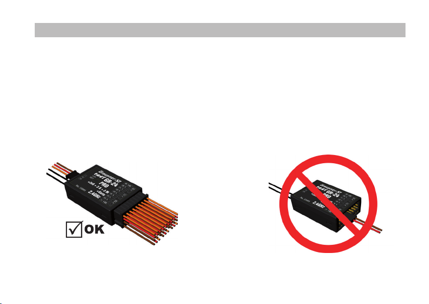
Caution!
The receiver must not make physical contact with the model’s fuselage, hull or chassis, as this would allow motor
vibration and landing shocks to be transferred directly to it.
Caution!
It is not permissible to carry out modications of any kind to the receiver. Any changes invalidate product approval, and
you forfeit any insurance protection.
Caution!
Ensure that the equipment is working correctly and at full range before every ight. Check the state of the batteries at
regular intervals.
Note!
Ensure that all your HoTT components are loaded with the current version of the software at all times.
Note!
Safety is no accident, and radio-controlled models are not playthings!
41
Page 7

GENERAL NOTES
• The receiver’s integral gyros are very fast, high -resolution components. This means that you should always use
high-speed digital servos wherever possible, so that the gyro’s corrective signals are converted directly and accurately
into servo movement; this helps to prevent the model oscillating.
• Keep all servo extension leads as short as possible.
• When switching on or adjusting the radio control system, it is essential to keep the transmitter aerial at least 15 cm
from the receiver aerial(s). If the transmitter aerial is too close to the receiver aerials, the receiver will be swamped
and the red LED on the receiver will light up. The transmitter responds with a ashing red LED and repeated beeps at
approximately one-second inter vals, i.e. the radio control system reverts to fail-safe mode. If this should happen,
increase the distance until the audible warning ceases, and the blue transmitter LED lights up constantly once more.
The red LED on the receiver should now be o.
2. FUNCTIONS
2.1. BINDING
The Graupner/SJ HoTT 2.4 receiver must be “bound” to “its” Graupner/SJ HoTT 2.4 RF module (transmitter) before a radio
link can be created between them; this process is known as “binding”.
Binding is only necessar y once for each combination of receiver / RF module, so the binding procedure described below
only needs to be repeated if you add more receivers. However, binding can be repeated at any time if you wish;
for example, if you switch transmitters.
This is the procedure in detail
• Binding is only possible if the receiver has not been linked with a bound transmitter since being switched on (red LED
lights); press the SET button to set the receiver to BIND mode.
• If you have already bound a receiver to the transmitter, and wish to bind the receiver to a new model memory, this is
the procedure:
42
Page 8

• Switch the transmitter’s RF section o in the “Basic model settings” menu.
• Switch the receiver on, and press the SET but ton to set it to Bind mode.
• Initiate binding in the transmitter’s “Basic model settings” menu.
• The red receiver LED should go out within about ten seconds. If it does, the binding process has been completed
suc cessf ully.
• Your transmitter / receiver combination is now ready for use.
• However, if the red LED continues to glow, then the binding process has failed. If this should happen, repeat the whole
procedure.
2.1.1. BINDING MULTIPLE RECEIVERS PER MODEL
If necessary it is also possible to bind more than one receiver to a par ticular model. First bind each receiver individually as
described earlier.
When the system is actually in use, the receiver which was last bound acts as the Master unit, and any telemetr y sensors
installed in the model must be connected to this receiver, as only the Master receiver transmits the data to the ground
using the downlink channel. The second - and any other - receivers operate in Slave mode, in parallel with the Master
receiver, with the downlink channel switched o.
The channel mapping function of HoTT telemetr y also allows the control functions to b e divided up amongst multiple
receivers, or alternatively the same control func tion to be assigned to multiple receiver outputs. For example, this is useful
if you wish to actuate each aileron with two servos instead of just one.
2.2. Fail-Safe FUNCTION
In the receiver’s default state, all connected ser vos remain in their last valid position (“Hold” mode) if a fail-safe situation
should arise. In fail-safe mode the red LED on the receiver lights up, and the transmitter generates an audible alert by
beeping at a rate of around one per second.
You can exploit the safety potential of this option by at least setting the throttle position (for internalcombustion
43
Page 9

powered models) to Idle, or the motor function (electric-powered models) to “Stop”, or “Hold” for a model helicopter,
if a fail-safe event should occur. These settings ensure that the model is less likely to y out of control if interference
should occur, thereby helping to avoid property damage or even personal injury.
Read the operating instructions supplied with your radio control system for more details.
The gyro system remains active in a fail-safe situation.
2.3. RANGE-CHECKING
The range of your Graupner/SJ HoTT 2.4 system can be checked as described in the following instructions. We recommend
that you ask a friend to help you with the procedure.
Ideally the receiver should already be bound to the transmitter. Install it in the model in its nal p osition.
• Switch the radio control system on, and wait until the red LED on the receiver goes out. The servo movements can now
be observed.
• Place the model on a at surface (pavement, close-mown grass, earth), and ensure that the receiver aerials are at least
15 cm above the ground. It may be necessary to pack up the model to achieve this for the period of the range-check.
• Hold the transmitter away from your body at hip-level. Don’t point the transmitter aerial straight at the model; instead
rotate or angle the aerial tip in such a way that it is vertical when you operate the transmit ter controls.
• Select range-check mode, as described in the transmitter instructions.
• Walk away from the model, moving the transmitter stick s. If you detect an interruption in the radio link at any time
within a distance of about 50 m, see if you can reproduce the problem.
• If your model is tted with a motor or engine, switch it on or start it, so that you can check eective range when
potential interference is present.
• Walk further away from the model to the point where full control is no longer possible.
• At this point you should manually switch o range-check mode.
44
Page 10
The model should now respond to the controls again. If this is not 100% the case, do not use the system. Contact the
Graupner/SJ Service Centre in your locality and ask their advice.
We recommend that you carry out a range -check before every ight, simulating all the servo movements which occur in
ight. To guarantee reliable model operation, radio range must always be at least 50 m on the ground.
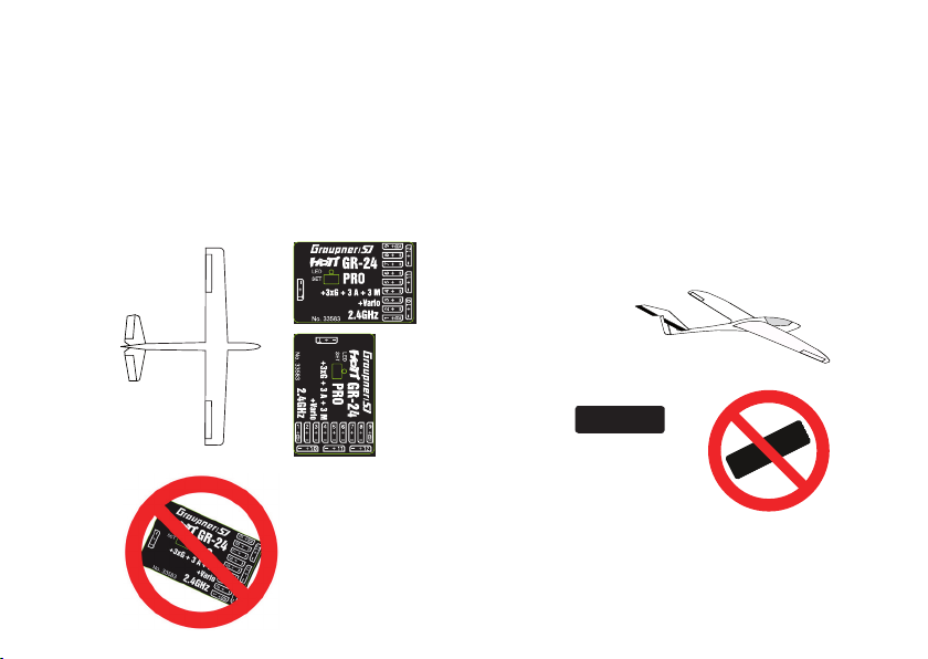
2.4. INSTALLATION IN THE MODEL (AIRPL ANE)
The gyro receiver must be installed straight and at right angles to aircraft longitudinal axis, so that the rotors can work as
intended, because of the accelerometer in addition also horizontal to the longitudinal axis.
OK
OK
45
Page 11
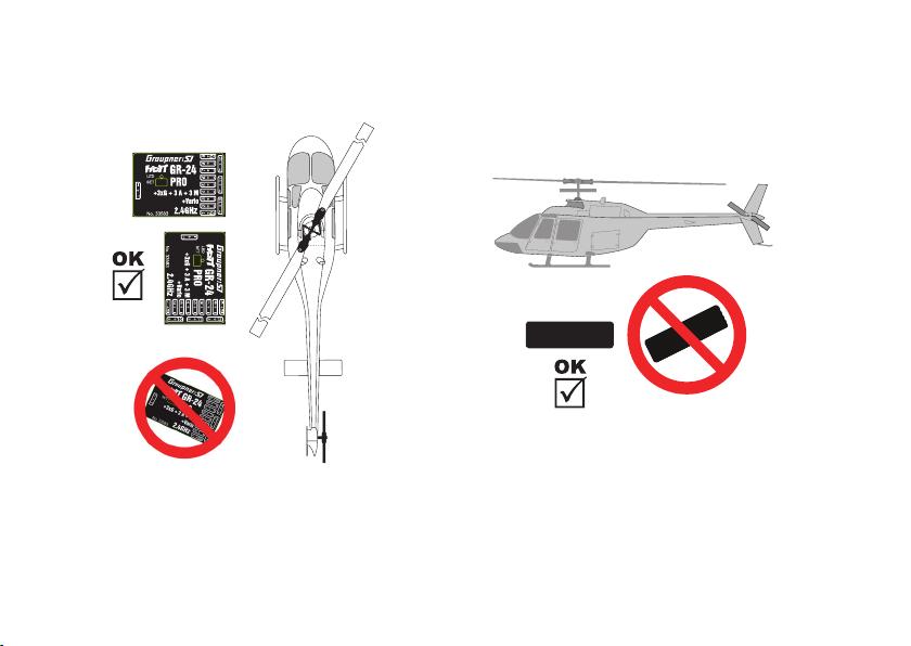
2.5 INSTALLATION IN THE MODEL (Heli)
The receiver has to be aligned strictly at right angles and parallel to the oor on the receiver platform on the helicopter.
46
Page 12
3. RECEIVER
3.1. CONNECTIONS
Connect the servos to the row of sockets on one end of the receiver. The connectors are polarised: note the small chamfers
on one side. Never use force - the connectors should engage easily. The polarity is also printed on the receiver;
the negative wire (-) is brown, the positive (+) red and the signal orange.
The servo sockets of Graupner/SJ HoTT 2.4 receivers are numbered sequentially. The socket for channel 6 can also be
programmed to deliver a (digital) sum signal (see section 3.2: Receiver set-up).
I²C (Inter-Integrated Circuit) - socket currently not active; for servicing purposes only!
Power supply
47
Page 13

Power supply
The receiver does not feature specic sockets for connecting the battery. We recommend that you connec t the power
supply to the socket(s) close to the servos already connec ted to the receiver. If you wish to connect multiple separate
batteries, the batteries must be of the same nominal voltage and capacit y. Never connect batteries of dierent type, or
packs of greatly diering states of charge, as this can cause eects similar to a short-circuit. If you encounter this problem,
we recommend the use of a voltage stabiliser unit (e.g. PRX-5A receiver power supply, Order No. 4136) between
the batteries and the receiver.
Telemetry (T/9 at GR-18)
The optional telemetry sensors are connected to the socket marked “T” (T/9)- Telemetry. In addition, the update is
performed on this socket (see point 5). At the GR-18, the socket can be used optionally for K9.
PROGRAMMING THE GENERAL RECEIVER SETTINGS
The receiver can be programmed using a suitable HoTT transmitter or the SMART-BOX (Order No. 33700).
3.2 RECEIVER SET-UP MENU GR-24
48
The receiver set-up menu
appears in the “Telemetr y” menu
under SET TINGS / DISPLAYS;
alternatively - if you are using a
SMARTBOX - under SETTING &
DATAVIEW. The method of
accessing this menu is
described in the operating
instructions supplied with your
transmitter or the Smar t-Box.
RECEIVE R SET-UP MENU GR-18
Page 14

Display Explanation Settings
REC EIVE R 1.0 1.0 indicates the version of the receiver’s rmware -
TYPE OF M ODEL Selection of modeltype Plane, Heli
ALARM VOLT. Alarm threshold for the receiver’s low voltage
ALARM TEMP.
Max. altitude
PERIOD Cycle time (frame rate) in ms 10 / 20 ms
SUMD at CH 8 (6) Digital sum signal at channel 8 (6) Yes / No
Sensor a t CH 9 Telemetr y-Sensor at channel 9 (only at GR-18) Yes / No
LANGUAGE
warning
Receiver overheating warning
Maximum altitude
Select menu language
Model type selection (Type of model)
here you can choose the model type.
By selec ting “Plane” you will be able to access the gyrosettings for surface models, as described in chapter 4.
The selection “Heli” will be made available through a future software update. It will enable a receiverintegrated ybarless
system, which can be adjusted inside the transmitters telemetry settings.
2.5 - 24.0 V
Default setting: 3.8 V
50 - 80° C
Default setting: +70° C
0 - 2500 m
in 25 m increments
German, English, French,
Italian, Spanish
49
Page 15

Low-voltage warning (ALARM VOLT )
if the receiver voltage falls below the set value, a low-voltage warning is generated by the transmitter’s RF module in
the form of the “general alarm tone”: a regular beeping at a rate of about one per second; alternatively the speech output
message “Receiver voltage”.
Temperature warning (AL ARM TEMP)
if the receiver temperature exceeds the set temperature threshold, a warning is generated by the transmitter’s RF module
in the form of the “general alarm tone”: a regular beeping at a rate of about one per second; alternatively the speech
output message “Receiver temperature”.
Maximum altitude (Max. altitude)
at this point you can enter a maximum altitude, at which an alarm is triggered, either via the transmitter’s RF module in
the form of the “general alarm tone”: a regular beeping at a rate of about one per second; alternatively the speech output
message “Height”. Note: the model’s actual height is adopted as zero when the receiver is switched on; the indicated
height is therefore the altitude relative to the launch point.
Cycle time (PERIOD):
if your system is used exclusively with digital servos, you can set a cycle time (frame rate) of 10 ms at this point. If your
system includes some or all analogue servos, you should always select 20 ms, as many analogue servos cannot process
the higher frame rate, and may respond by “jittering” or “growling”.
HoTT sum signal (SUMD)
if you activate the digital sum signal at channel 8, a sum signal containing eight channels is present at this socket, instead
of a servo signal. The HoTT receiver congured as SUMD constantly generates a digital sum signal from 8 control signals
from the transmitter and makes this signal available at the appropriate servo socket, which is receiver-specic.
At the time these instructions were revised, this type of signal is used by several of the latest electronic developments in
the area of ybarless systems, heavy-duty airborne power supplies, etc.
50
Page 16

WARNING: if you wish to use this facility, it is essential to observe
the set-up information supplied with the devices connected to the receiver,
otherwise there is a risk that your model may be uncontrollable!
Menu item only at 33579 GR-18 PRO 3XG +3 A + Vario
Telemetry sensor (sensor at K9): This jack allows you to use either for telemetry or for an extra channel (9). (Note: Both
together is not possible!) Switching is done in this menu item. If you select „Yes“, the socket is connected to the connection
of a sensor. If you select „No“ a jack is connected to the control channel 9.
3.3. FREE MIXERS
Impor tant note: If you w ish to use the gyr os, you must alwa ys set the tail
type to ‘n ormal’ in the t ransmitte r’s model typ e menu. If your mo del
is a delt a, features a V-ta il, or has two e levator servos ,
you must u se the receiver m ixer - not the tran smitter mix er - to
contro l these contro l surfaces, s ince the gyro st abilisati on system will
The four r eceiver mixer s work ‘downstrea m’ of the gyros . If you have
already programmed mixer functions in the “Wing mixers” or
“Free mi xers” menu of you r HoTT transmit ter, you must ensu re
that tho se mixers do not o verlap with thos e available in t his menu!
have no eect on these servos otherwise.
51
Page 17

SCREEN DISPLAY KEY SETTINGS
MIXER Mixer select 1, 2,....., 4
FROM CHANNEL Signal source / source channel 0,1,2,...6
TO CHANNEL Target channel 0,1,2,...6
TRIM Trim position in % -15 - + 15%
TRAV EL - Travel limit at % Servo travel -150 bis +150 %
TRAV EL + Travel limit at % Servo travel -150 b is +150%
Mixer
up to four mixers can be programmed simultaneously. You can switch between Mixer 1, Mixer 2, … and mixer 4 in the
“Mixer” line. The following settings only aect the mixer selected in this line.
From channel
the signal present at the signal source (or source channel) is mixed in to the target channel (TO CHANNEL) to an ex tent
which can be set by the user. The method of set ting up the values is analogous to the “Free mixers” menu in HoTT
transmitters.
To channel
part of the source channel signal (FROM CHANNEL) is mixed into the target channel (TO CHANNEL). The mixer ratio is
determined by the percentage values entered in the “ TRAVEL-“ and “TRAVEL+” lines. Select “0” if you do not require
the mixer.
52
Page 18

Mixer ratio (TRAVEL-/+)
in these two lines you can dene the mixer ratio in relation to the source channel (FROM CHANNEL); the value is set
separately for both directions.
PROGRAMMING EXAMPLES
V-tail with rudder dierential
Dierential is not normally necessar y with this tail type. Mixer 3 is not required if you do not need rudder dierential, and
TRAVEL- for mixer 2 must then be set to -100%. Alternatively you may prefer to carry out the programming using
the transmitter menu. A ‘Rudder elevator’ mixer can be set up at the transmitter instead of ‘Free mixer 3’ at the receiver;
the mixer should be set up asymmetrically, e.g. +30%, -30%. This option frees up one mixer at the receiver.
53
Page 19

Delta with aileron dierential (1 aileron)
In this example aileron dierential is set to 40%. Alternatively you may prefer to carry out the programming using
the transmitter menu. An ‘Aileron elevator’ mixer can be set up at the transmitter instead of ‘Free mixer 3’ at
the receiver; the mixer should be set up asymmetrically, e.g. +30%, -30%. This option frees up one mixer at the receiver.
Two elevator servos (channel 6 for the second elevator servo)
54
Page 20

Only for transmitters without a buttery (crow) mixer (e.g. mx-10 HoTT)
If a buttery (crow) mixer is required, you will not be able to use one of the t wo functions ‘dierential’ or ‘landing ap’
adjustment, as two mixers are needed for this.
Programming example
Programming example
55
Page 21

3.4. ASSIGNING THE GYRO AXES
Aileron servos
You should enter the value 2 in this line if your model has two aileron servos; in this case the gyro for channel (servo) 2 also
acts on servo 5. If the ailerons are also used as aperons or speedbrakes, gyro suppression is based on the sum of both
channels.
CAUTIO N: the servo reve rse setting m ust be the same fo r both aileron s ervos, i.e. e ither both
‘normal ’ or both ‘rever se’. If this is not po ssible, on no ac count should y ou reverse one se rvo in
the tran smitter men u. The only opti on is to re-ins tall it in the mod el by turning it ro und physicall y.
However, if yo ur model is tt ed with progra mmable servo s (e.g. Graupne r DES, HVS or HBS t ypes
- see the i nstruction s for the update p rogram ‘Firmwa re_Upgrad e_grStudio - t hen it is possi ble to
Please read the installation notes on page 5 of these instructions. The rst step is to dene the three gyro axes and the
orientation of the receiver. This is accomplished by switching on the transmitter and model, and selecting ‘New setting:
yes’ in the receiver’s ‘Gyro settings’ menu.
56
reverse t he directio n of rotation at th e servo itsel f.
Page 22

• Now move the stick for any control surface to full travel in one direction; in the following example we use the aileron
channel.
• The detec ted axis (aileron) is highlighted (black background). (In the receiver’s default state the value for all axes is
shown as ‘+0’; the axes can also be set manually to ‘+0’. 0 = inaktiv).
• Now turn the model through at least 45° in the direction corresponding to the stick movement. For example, if you
moved the aileron stick to the left, you must simulate a left turn with the model move the left wing down through
at least 45°.
• This process denes the one axis and direction; now you must repeat the procedure for the other two axes.
• The gyro axis 1, 2 or 3 is now displayed in the ‘Aileron / Elevator / Rudder’ display; a negative prex will appear if servo
reverse is activated.
• Once all three axes are dened, the display automatically reverts to ‘New setting: no’.
WARNING : once you have com pleted this pro cedure, it is a bsolutely es sential to che ck that all
the gyro s are working in t he correct dir ection. This i s accomplis hed by moving
the mode l around all th ree axes in tur n, and checki ng the control su rface deec tions - see dia grams
below. You mus t not y the model b efore doing th is: crash haza rd!
57
Page 23

EL EVAT OR
Model movement Cont rol surfac e response (s een from the t ail)
RUDDER
Model movement Cont rol surfac e response (s een from the t ail)
58
Page 24

AILERON
Model movement Control sur face respo nse (seen fro m the tail)
59
Page 25

3.5. ADJUST SERVO LIMIT FOR CHANNELS
In this menu, you can limit the servo travel for all channels.
Limit the servo travel to the maximum possible deection, so
that the ser vos can not run in the stop in the gyro operation.
Move the cursor to the desired line (by further downward
move of the cursor will be displayed further channels),
here „1“ for channel 1 Pressing the SET button is
pressed the „SEL“ eld in „STO“.
Now move the stick of channel 1 in the desired direction
and position, while the corresponding
percentage display is shown inverted.
Now press the SET button again and the set value
is displayed and stored. Go through the procedure
for the other channels.
4. PROGRAMMING THE GYRO SETTINGS
PID (Proportional Integral Dierential) correction
The stabilising eec t of the gyro sensors is based fundamentally on three parameters
P factor: denes proportional correction
P = propor tional: if the intended value is not the same as the actual value, then the dierence is fed proportionally into
the correc tive signal; in simple terms, the input value (e) is multiplied by a xed value: u(t) = Kp*e(t).
Kp is termed the amplication value. The output value is therefore propor tional to the gyro’s input value. Propor tional
60
Page 26

correction cannot occur until a deviation from the intended value is present; if the deviation is 0, then the product is also
zero. If the amplication value is set too high, the P factor causes the model to oscillate and become unstable.
I factor: integral correction (not currently implemented)
D factor: denes dierential correction
D = dierential: in this case the corrective output value is aected by the rate of change of the input value, i.e. the faster
the model tilts around the axis, the more pronounced the correc tive response of the gyro. If the model changes attitude
very gently, then the D factor causes hardly any corrective action. It also makes absolutely no dierence how far the model
has already changed attitude; the crucial value is only the speed or rate of the movement.
The rate of change is again multiplied by a factor (as with P correction) to produce the output value. For this reason pure
D correction is not used; it must always be employed in combination with P correction.
4.1. PROGRAMMI NG PID CORRECTION - GYRO SETTINGS DISPLAY
CAUTIO N: before you sta rt entering s ettings for a ne w model, it is es sential to sel ect the numbe r of
ailer on servos in the A ileron ser vos menu point , and to dene the g yro axes and orie ntation in th e New
settings menu point.
Aileron / Elevator / Rudder
Shows the programmable P factors for the corresponding control surface.
Note: the gyro axes must rst be dened under New settings (see section 3.4).
If you wish to disable the gyro, enter the value OFF in the appropriate control function.
61
Page 27

P factor
The P factor should always be set rst, followed by the D factor (adjustment range in each case 0 to 10). A general rule is
that the larger the control surface, the smaller the P factor required. Start with a factor of 2 (default set ting), and do not
exceed 4 - 5 as maximum value for the normal ight phase, 2 - 3 for speed, 3 - 6 for landing; the maximum value of
10 should be reserved for torque-rolls only.
WARNING : if you program s eparate igh t phases, it is e ssential to se lect the appr opriate igh t phase
when the m odel is in the ai r, as inapprop riate gyro sett ings may cause t he control sur faces to osci llate,
possibly resulting in the loss of the model!
Note: the higher the model’s speed, the more quickly oscillation may set in.
D factor
For a given P factor setting, the model’s tendenc y to oscillate can be reduced by setting a lower D factor. However, if
you selec t a lower setting for the P factor, then you may be able to set a higher D factor value before the onset of control
surface oscillation. The gyro eect can be optimised by netuning the D factor.
Note: the standard P and D values should cause the gyros to correct the model’s attitude quickly when
it is upset by an outside inuence, without causing oscillation, but in practice the optimum values
for a particular model can only be found by ight-testing. If the model displays little or no automatic
stabilisation with the default settings, the value should be raised; on the other hand, if the model
oscillates (wave-like movements in ight), the value should be reduced.
If your transmitter has spare propor tional controls, you can use them to adjust the values while the model is ying.
Some transmitters allow the correc tive factors to be altered during a ight using the proportional controls, whereas
others allow xed values only.
62
Page 28

4.2. PROGRAMMING THE FACTORS
4.2.1. Programming, transmitter with proportional controls
If your HoTT transmitter is equipped with propor tional controls, it is also possible to adjust the P and D factors for each
axis during a ight: what you might call ‘ying the settings’.
You need to assign proportional controls (e.g. the sliders on the mc-20) to any channel in the range 5 to 16 (in this example
channel 9); now you can alter the P factor (and the D factor) using these controls. In each case the current values are shown
in brackets.
Procedure, using the ailerons as an example
• Move the cursor to the appropriate line, in this case “Ail” for aileron.
• Press the SET button to activate the Channel eld.
• Select the appropriate channel, and save the setting with pressing
the SET but ton again
• Move the corresponding proportional control to alter the factor
(adjustment range 0 - 10; 0 means no gyro correction for that axis).
• You can also adopt this factor directly by pressing the left button < or
the right button >. This frees up the channel previously occupied by
the proportional control, so that it can be used for some other purpose,
e.g. for elevator or rudder.
• Move on to elevator and / or rudder, and select the channel and factor (you can either select the same channel, in order
to alter all the axes simultaneously, or dierent channels, allowing you to program the axes individually).
• Move the cursor to the Factor line, where you can also change the P factor for aileron, elevator and rudder with priority
(adjustment range up to 200%).
• Move the cursor to the D factor line, where you can alter the D factor for aileron, elevator and rudder with priority using
a propor tional control (adjustment range up to 200%; channel value -100% equates to a factor of 0%, channel value 0%
equates to 100%, and +100% equates to 200%). This makes it a very easy matter to match the gyro’s corrective eect to
the model ’s airspeed. In particular, higher gyro gain can be used for the landing approach - without the need to switch
ight phases.
63
Page 29

• Now test-y your model and ne-tune the values one by one until your preferred stabilising eect is achieved without
the model oscillating.
• It may be sensible or easier to activate the gyro for one axis only at rst, and then to establish the optimum setting for
that axis, rather than for several axes simultaneously.
4.2.2. Programming, transmitter without proportional controls
• Move the cursor to the appropriate line, in this case “Ail” for aileron.
• Press the SET button to activate the Channel eld, select the appropriate
value (1 - 10 of OFF), then press the SET button to save it.
• First select a low value (see P factor section for starting points) and carry
out a test- ight. If gyro stabilisation is not su ciently pronounced,
increase the value step by step until the level of correction is as required;
if the model already oscillates, reduce the value step by step.
• Do not select a channel (Ch5 - Ch16); this function is only relevant to
transmitters with proportional controls.
• Move on to elevator or rudder and select the desired value (or OFF).
• Leave the settings for “Factor” and “Factor D” at OFF.
• It may be sensible or easier to activate the gyro for one axis only at rst, and then to establish the optimum setting for
that axis, rather than for several axes simultaneously.
Once you have found the optimum settings, you can set up a transmitter switch to control the gyro, i.e. for switching
between gain settings. For example, you could assign a three-position switch to “Factor” and “Factor D”, and then use it to
switch the values between 0% (OFF), 100% and 200%.
Flight phase specic settings
It is possible to use a channel to control the fac tor value by setting up ight phase speci c transmitter control settings,
but only if the transmitter is an MX20 / MC20 or MC32; please see the instructions supplied with your transmitter and refer
to the “Transmit ter control settings” and “Flight phase settings” menu points for more information.
64
Page 30

4.3. INITIALISING THE GYRO
After switching on the model of the gyroscope is immediately ac tive but not yet initialized. To initialize it, you keep your
model when switching quiet and straight in level ight - the best place it on the at ground or a at table.
After about 2 seconds, the ailerons move up and down just once. This “wiggle” signaled the successful initialization,
the end of the calibration, only then the model may be moved again.
All sticks are to be kept strictly in neutral!
WARNING : during the ini tialisati on phase the gyr o detects the mo del’s neutral a ttitude, an d for this
reason i t is absolutel y essential t o leave the model i n its ‘normal igh t attitude’ d uring the act ivation
phase , and avoid moving i t! If you neglec t this, the gyr o may detect an in correct ight a ttitude, wi th
the resu lt that the mod el will not y as you e xpect it to. It ma y be di cult to con trol, and coul d even
crash!
Durin g the initiali sation phase t he receiver al so detects the c entre points o f the individu al control
channels; this information is used for gyro suppression. Gyro suppression reduces the stabilising
actio n progressive ly as the trans mitter contr ols are de ect ed away from cent re; at +/- 100% the gyro
is completely disabled.
YOUR MODEL IS NOW READY TO FLY .. !
65
Page 31

5. FIRMWARE UPDATE - Graupner 33579 / 33583 HoTT Receivers
Firmware updates are loaded into the receiver via the Channel 5 output, using a PC running Windows XP, Vista or 7.
You will also need the separately available USB interface, Order No. 7168.6 and the adapter lead, Order No. 7168.6A or
7168.S (33575: additional adapter lead, Order No. 33565.1).
The programs and les required for this can be found in the Download area for the corresponding products at
www.graupner.de.
Connect the adapter lead to the USB interface,
Order No. 7168.6. The connec tors are polarised: note the small
chamfers on one side. Never use force - the connectors should
engage easily.
5.1. REC EIV ER
Connect the adapter lead to receiver as shown in the picture.
The connectors are polarised: note the small chamfers on one
side. Never use force - the connectors should engage easily.
The black wire must be at the top (-), the orange wire at
the bottom (T).
66
Page 32

5.2. UPDATE PROCEDURE
Start “Slow yer/Gyro receiver update”
The “Slow yer/Gyro receiver update” program is best called up from the “Firmware_Upgrade_grStudio” program. Click
on the “Slow yer/Gyro receiver update” point under “Link” in the left-hand function menu (alternatively selec t the appropriate entry “Micro Receiver Upgrade” under “Menu”).
It is also possible to start the associated application program directly by double- clicking on the le “micro_gyro_swloader.
exe”. You will nd this .exe le in the “Graupner_PCSoftware” folder of the “HoTT_Software VX” package.
A program window now appears in which you should rst set the “correct ” COM port for the USB interface,
Order No. 7168.6, in the Selec t window.
If you are not sure of this, check the COM port in the “Selec t Port ” window in the “Controller Menu” (see above), and note
down the COM port number at the “Silicon Labs CP210x USB to UART Bridge” entry – in this case “COM03” (if you select the
wrong por t, you will be alerted to this when you read out the receiver data).
Click on xx in order to load the corresponding rmware le named “MicroStabi7X_V_ XX.bin” from the hard disc (“XX”
stands for the version number.)
67
Page 33

When the le has loaded, click on Start …
… connect the receiver, and switch it on.
68
Page 34

The progress bar shows the transfer proceeding normally. The receiver LED is o during this period, then ashes as soon
as the le transfer is complete.
Please refer to th e detailed update instruc tions in the Download are a for the corresponding item a t http://www.graupner.de.
69
Page 35

6. DECLARATION OF CONFORMITY
Declaration of Conformity in accordiance with the Radio and Telecomunikations Terminal Equipment
Act (FTEG) and Directive 1999/5/EG (R&TTE)
Graupner/SJ GmbH, Service Department,
Henriettenstr. 96, D-73230 Kirchheim/Teck, Germany
declares that the product
GR-24 PRO +3xG + 3A + 3M HoTT
GR-18 PRO +3xG + 3A HoTT
Equipment class:
complies with the essential requirements of § 3 and the ot her relevant provisio ns of the FTEG (Articl e 3 of the R&TTE Directive).
Harmonised standards applied
EN 60950-1:2006+A11
EN 301 489-1 V1.9.2
EN 301 4 89-17 V2 .1.1
EN 300 328 V1.7.1
Kirchheim 17. April 2013
70
1
Health and safety requirements pursuant to § 3 (1) 1. (Article 3 (1) a))
Protection requirement concernig electromagnetic compatibility § 3 (1) 2, Artikel 3 (1) b))
Measures for the ecient use of the radio frequency spectrum § 3 (2) (Article 3 (2))
0678
Ralf Helbing
Managing Director
No. 33583
No. 33579
Page 36

7. MANUFACTURER’S DECLARATION
Content o f the manufact urer’s decla ration
If material defects or manufacturing faults should arise in a product distributed by us in the Federal Republic of Germany
and purchased by a consumer (§ 13 BGB), we, Graupner/SJ GmbH, D -73230 Kirchheim/Teck, Germany, acknowledge
the obligation to correc t those defects within the limitations described below.
The consumer is not entitled to exploit this manufacturer’s declaration if the failure in the usability of the product is due to
natural wear, use under competition conditions, incompetent or improper use (including incorrect installation) or external
inuences. This manufacturer’s declaration does not aect the consumer’s legal or contractual rights regarding defects
arising from the purchase contract between the consumer and the vendor (dealer).
Exte nt of the guaran tee
If a claim is made under guarantee, we under take at our discretion to repair or replace the defec tive goods. We will not
consider supplementary claims, especially for reimbursement of costs relating to the defect (e.g. installation / removal
costs) and compensation for consequent damages unless they are allowed by statute. This does not aect claims based on
legal regulations, especially according to product liability law.
Guarantee requirements
The purchaser is required to make the guarantee claim in writing, and must enclose original proof of purchase
(e.g. invoice, receipt, delivery note) and this guarantee card. The purchaser must send the defective goods to us at his own
cost, using the address stated below.
Graupner/SJ GmbH, Service Department,
Henriettenstr.96, D 73230 Kirchheim/Teck, Germany
Service Department: tel. [0049] 7021-722130
The purchaser should state the material defect or manufacturing fault, or the symptoms of the fault, in as accurate
a manner as possible, so that we can check if our guarantee obligation is applicable.
The goods are transpor ted from the consumer to us and from us to the consumer at the risk of the consumer.
71
Page 37

Duration of validity
This declaration only applies to claims made to us during the claim period as stated in this declaration. The claim period
is 24 months from the date of purchase of the produc t by the consumer from a dealer in the Federal Republic of Germany
(purchase date). If a defect arises after the end of the claim period, or if the evidence or documents required according to
this declaration in order to make the claim valid are not presented until af ter this period, then the consumer forfeits any
rights or claims from this declaration.
Limita tion by lapse of t ime
If we do not acknowledge the validity of a claim based on this declaration within the claim period, all claims based on this
declaration are barred by the statute of limitations after six months from the time of implementation; however, this cannot
occur before the end of the claim period.
Applicable law
This declaration, and the claims, rights and obligations arising from it, are based exclusively on the pertinent German Law,
excluding the norms of international private law, and excluding UN retail law.
8. ENVIRONNEMENTAL PROTECTION NOTES
When this product comes to the end of its useful life, you must not dispose of it in the ordinary domestic
waste.
The correct method of disposal is to take it to your local collection point for recycling electrical and
electronic equipment. The symbol shown here, which may be found on the product itself,
in the operating instructions or on the packaging, indicates that this is the case.
Individual markings indicate which materials can be recycled and re-used. You can make an important
contribution to the protection of our common environment by re-using the product, rec ycling the basic
materials or recycling redundant equipment in other ways.
Remove batteries from your device and dispo se of them at your local collection point for batteries.
In case of R/C models, you have to remove elec tronic parts like servos, receiver, or speed controller from the product in
question, and these parts must be disposed of with a corresponding collection point for electrical scrap.
If you don’t know the location of your nearest disposal centre, please enquire at your local council oce.
72
Page 38

ZÁRUKA / WARRANTY
Na tento výrobek je záruka
Warrantied for
Graupn er/SJ GmbH, Henrie ttenstraße 9 6, 73230 Kirchheim/ Teck, Německo
posky tuje na tento vý robek záruku p o dobu 24 měsíců od dat a nákupu.
Záruka s e vztahuje po uze na ty vady mate riálu nebo zpra cování, které byl y
přítomny u ž v době zakoupen í výrobku. Na p oškození způsob ené opotřeben ím,
přetížením, nevhodným zacházením nebo použitím nevhodného příslušenství se
záruka n evztahuje. Z ákonná záruka a p ráva spotřebite le nejsou těmito z áručními
podmín kami dotčena. Pečl ivě prosím výro bek zkontrolujt e předtím, než
uplatní te nárok na záruku n ebo nám výrob ek zašlete, jsme to tiž nuceni vám
naúčtovat naše náklady pokud se výrobek ukáže bezvadným.
Graupner/SJ GmbH, Henriettenstrasse 96, 73230 Kirchheim/Teck, Germany
guarante es this product f or a period of 24 month s from date of purchas e.
The guar antee applies onl y to such material or op erational def ects witch are
present a t the time of purchas e of the product.
Damage du e to wear, overloading , incompetent han dling or the use of inc orrect
accessor ies is not covered by th e guarantee. The us er´s legal r ights and claims
under gar antee are not aec ted by this guarant ee. Please check th e product
carefu lly for defect s before you are make a c laim or send the ite m to us, since we
are oblig ed to make a charge for o ur cost if the produ ct is found to be fre e
of faults.
Servis/Service
ČESKÁ REPUBLIKA
TRIVOX - Pat rik Dworsc hak
Do ub ra vi ce 11 0
533 53 Doub ravice
podpora@trivox.cz
www.trivox.c z
(+420) 226 519 671
Razítko a podpis prodejce
Stamp and signature of dealer
měsíců
months
Záruční list
Warranty certicate
33579 & 33583
GR-18PRO 3xG+3A+Vario
GR-2424PRO 3xG+3A+3M+Vario
Datum zakoupení
Date of purchase/delivery
Jméno majitele
Owner´s name
Adresa
Complete adress
73
Page 39

Specikace a dostupnost se mohou měnit. Dodáváno pouze sítí specializovaných modelářských prodejen.
Rádi vás budeme informovat o vašem nejbližším dodavateli.
Neodpovídáme za tiskové chyby.
Specications and availability subject to change. Supplied through specialist model shopsonly.
We will gladly inform you of your nearest supplier.
We accept no liability for printingerrors.
 Loading...