

Page 1
Manual
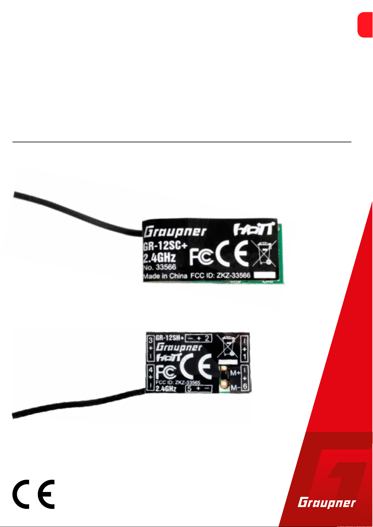
GR-12SH+ and GR-12SC+
6 channel 2.4 GHz HoTT receiver
No. 33565
No. 33566
EN
Copyright © Graupner/SJ GmbH
Page 2

Index
Introduction ......................................................................................4
Service centre ...................................................................................4
Intended use .....................................................................................5
Target group ....................................................................................5
Package content ................................................................................5
Technical data ...................................................................................6
Accessories .....................................................................................6
Connection table ............................................................................6
Symbol description ...........................................................................7
Safety notes ......................................................................................7
For your safety by handling the transmitter and the receiver .......8
For your safety by handling the batteries ......................................9
Installation ......................................................................................10
Connections ....................................................................................10
Power supply .................................................................................11
Binding .............................................................................................12
Setting and display of the receiver settings ..................................13
Display "Receiver" .........................................................................13
Display "Free mixer" .....................................................................15
Firmware update ............................................................................16
SIMPLIFIED DECLARATION OF CONFORMITY ................................18
Manufacturer ................................................................................18
Notes on environmental protection ..............................................19
Care and maintenance ...................................................................19
Warranty conditions .......................................................................19
2 / 20 3 / 20
33565_33566_GR-12Sx_DE_V1sh 33565_33566_GR-12Sx_DE_V1sh
Page 3
Introduction
Intended use
Thank you very much for purchasing a Graupner 33565 GR-12SH+
or 33566 GR-12SC+ receiver.
Read this manual carefully to achieve the best results with your HoTT
system but first of all to safely control your models. If you experience
any trouble during operation, take the instructions to help or ask
your dealer or Graupner Service Centre.
Due to technical changes, the information may be changed in this
manual without prior notice. Be always updated by checking periodically on our website, www.graupner.de to be always uptodate with
the products and firmwares.
This product complies with national and European legal requirements.
To maintain this condition and to ensure safe operation, you must
read and follow this user manual and all the safety notes before
using the product and you have to respect those notes also for future
use!
Note
This manual is part of that product. It contains important information concerning operation and handling. Keep these instructions for
future reference and give it to third person in case you gave the
product.
The receivers GR-12SH+ and GR-12SC+ HoTT may only be used for
the purpose intended by the manufacturer, for the operation of
slowflyer models whose components are equipped with SH or SC
plugs. The maximum range is adapted to this model type and is
about 300 m. These receivers are not suitable for models that generally require a greater range or whose servos exceed the maximum
permissible current of the SH (0.5 A max.) or SC (1 A max.) connectors. In general, the receivers GR-12SH+ and GR-12SC+ HoTT are not
suitable for the operation of all other types of UAVs or unmanned
aerial vehicles as well as all other types of unmanned land and water
vehicles. This type of use is not permitted and may result in significant damage to property and / or personal injury. No warranty or liability is therefore offered for any improper use not covered by these
provisions.
In addition, it is explicitly pointed out that you must inform yourself
about the laws and regulations applicable at your respective starting
point before starting the remote control operation. Such conditions
may differ from state to state, but this must be followed in every
case.
Note
Read through this entire manual before you attempt to install or use
the transmitter.
Service centre
Graupner Central Service
Graupner GmbH
Henriettenstrasse 96
D-73230 Kirchheim / Teck
Graupner USA
3941 Park Dr Suite 20-571
El Dorado Hills, CA 95762
Graupner in Internet For the service centers outside Germany please refer to our web site
www.graupner.de.
Servicehotline
(+49) (0)7021/722-130
Monday - Thursday:
9:15 am - 4:00 pm
Friday:
9:15 am - 1:00 pm
service@graupner.de
Website: www.graupnerusa.com
Phone: +1 855-572-4746
Email:service@graupnerusa.com
Target group
The item is not a toy. It is not suitable for children under 14. The
installation and operation of the receiver must be performed by
experienced modellers. If you do not have sufficient knowledge
about dealing with radio-controlled models, please contact an experienced modeller or a model club.
Package content
• Receiver 33565 GR-12SH+ or 33566 GR-12SC+ HoTT
• Manual
Note
Graupner/SJ works continuously to the further development of the
products. We must therefore reserve the right to change the scope
of delivery in terms of form, technology and equipment.
4 / 20 5 / 20
33565_33566_GR-12Sx_DE_V1sh 33565_33566_GR-12Sx_DE_V1sh
Page 4
Technical data
!
!
Symbol description
Accessories
Connection table
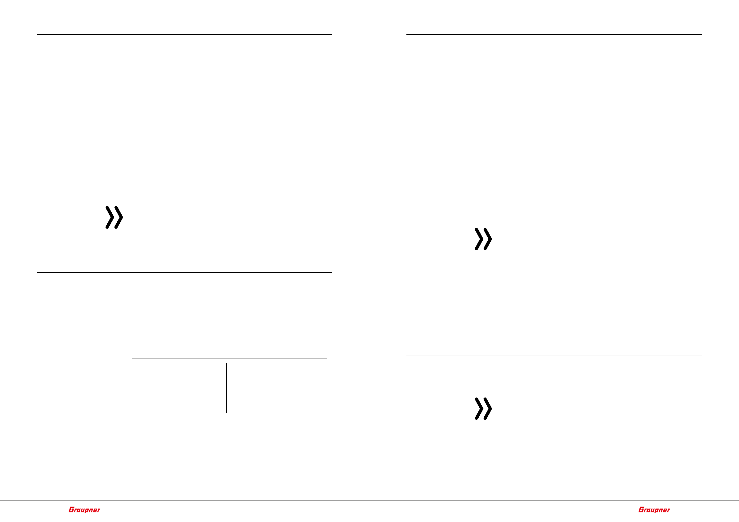
GR-12SH+ HoTT GR-12SC+ HoTT
No. 33565 33566
Connection socket
type
Max. permissible
current per port 0,5 A 1 A
Operating voltage
Frequency 2,4 GHz 2,4 GHz
Modulation FHSS FHSS
Transmission protocol
Control functions 6 6
Power consumption
Temperature range
Antenna length 1x 30 mm 1x 30 mm
Dimensions
Weight approx. 1,5 g approx. 1,5 g
ESC with SBEC
Note
Instead of a servo or motor controller connected to port "1", "Channel 1" can be used as an electronic speed controller via the solder
lugs marked "M +" and "M-". In this case, the continuous current of
the motor directly connected in this way may under no circumstances exceed 2 A! Otherwise, there is a considerable risk that the
receiver will be overloaded and consequently destroyed!
C5 SERVO and updates / SENSOR / VOLTAGE
SH SC
3,6 … 8,4 V 3,6 … 8,4 V
HoTT HoTT
approx. 20 mA approx. 20 mA
-15 ... +70 °C -15 ... +70 °C
20 x 12 x 7 mm 20 x 12 x 7 mm
GR-12SH+ HoTT GR-12SC+ HoTT
33718.SH 33718.SC
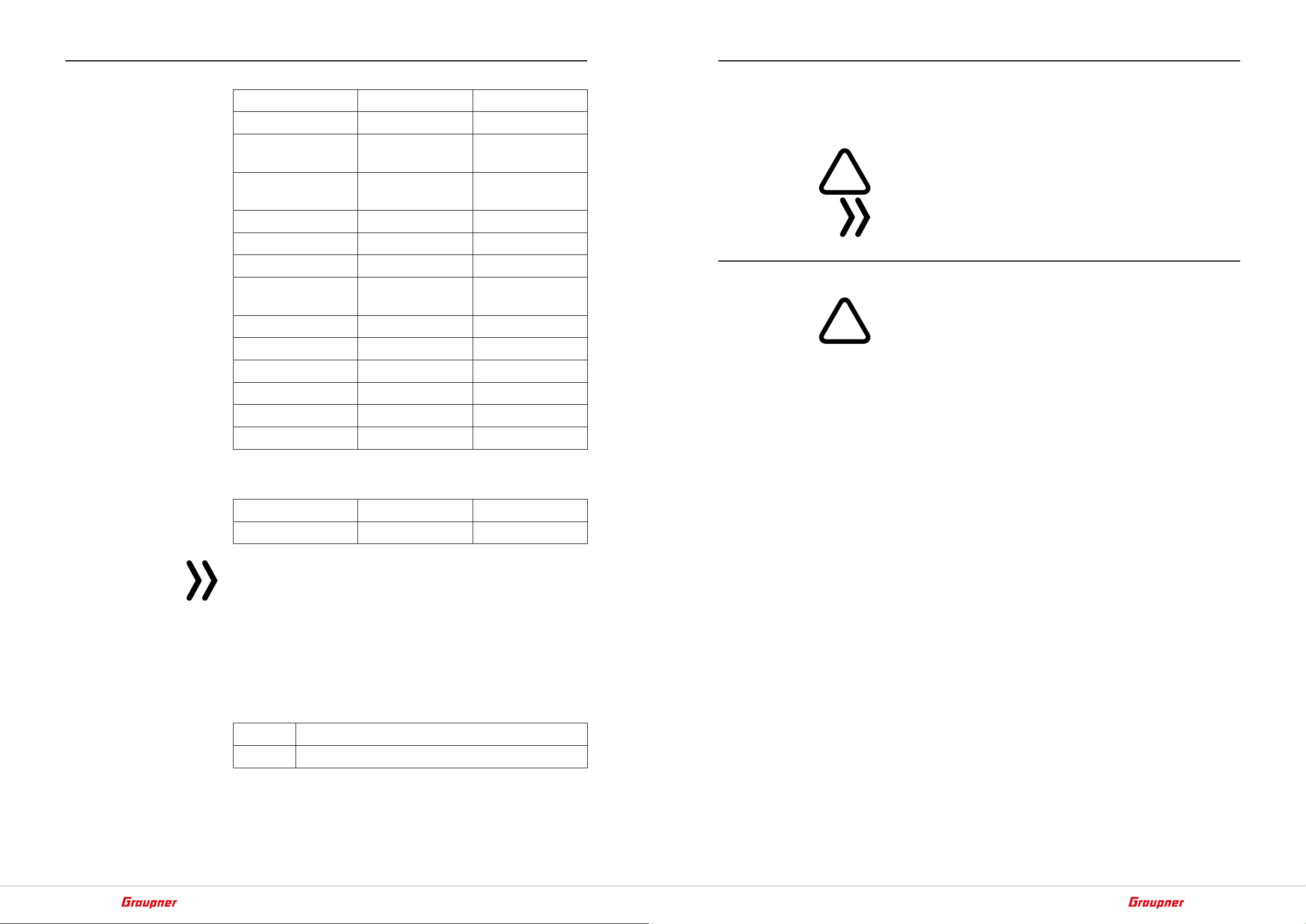
Always observe the information indicated by these warning signs.
Particularly those which are additionally marked with the words
CAUTION or WARNING.
The signal word WARNING indicates the potential for serious injury,
the signal word CAUTION indicates possibility of lighter injuries.
The signal word Note indicates potential malfunctions.
Attention indicates potential damages to objects.
Safety notes
These safety instructions are intended not only to protect the product, but also for your own and other people’s safety. Therefore please
read this section very carefully before using the product!
• Do not leave the packaging material lying around, this could be a
dangerous toy for children.
• Persons, including children, with reduced physical, sensory or
mental capabilities, or lack of experience or knowledge, or not
capable to use safely the receiver must not use the receiver without supervision or instruction by a responsible person.
• Operation and use of radio-controlled models needs to be learnt!
If you have never driven such a model, then start extra carefully
and make sure to be familiar with the reactions of the model to
the remote control commands. Proceed responsibly.
• First, always perform a range and function test on the ground (to
do so, hold your model tight), before you use your model. Repeat
the test with running motor and with short throttle bursts.
• Only use the components and spare parts that we recommend.
Always use matching, original Graupner plug-in connections of
the same design and material.
• Make sure that all of the plug-in connections are tight. When disconnecting the plug-in connections, do not pull the cables.
• Protect the receiver from dust, dirt, moisture and foreign parts.
It must be protected from vibration as well as excessive heat or
cold. The models may only be operated remotely in normal outside temperatures such as from -10°C to +55°C.
• Always use all your HoTT components only with the latest firmware version.
C6 SERVO ("No") or SUMD ("Yes")
6 / 20 7 / 20
33565_33566_GR-12Sx_DE_V1sh 33565_33566_GR-12Sx_DE_V1sh
Page 5

!
• Before you start using the remote control model, you have to
!
!
check the further relevant laws and regulations. These laws you
must obey in every case. Pay attention to the possibly different
laws of the countries.
In Germany for example, the insurance is mandatory for all kinds
of model operation. If you already have one, please inform yourself if the operation of the respective model is covered by your
insurance. If this is not the case, conclude a special liability insurance policy for models. In addition, models with a take-off weight
of 250 g or higher are to be provided with a fireproof sticker bearing the name and address of the owner. And for a model operation outside of designated model airfields usually a proof of
knowledge is always required.
• Due to safety and licensing reasons (CE), any reconstruction and/
or modification of the product is prohibited.
• If you have questions which cannot be answered by the operating manual, please contact us or another expert in the field.
For your safety by handling the transmitter and the receiver
For your safety by handling the batteries
CAUTION
• Protect the batteries from dust, dirt, moisture, heat and vibrations. Only use in dry locations.
• Do not use any damaged battery.
• Batteries may not be heated, burned, short-circuited.
• If handled improperly, there is a danger of fire, explosion, irritation and burns.
• Leaked electrolyte is caustic and should not be touched or
come into contact with your eyes. In case of emergency, rinse
with a large quantity of water and consult a Med. Doctor.
• Stock the batteries in dry and fresh conditions.
• Dispose of the battery in the proper disposal centers.
WARNING
Also while programming the transmitter, make sure that a connected motor cannot accidentally start. Disconnect the fuel supply or drive battery beforehand.
Avoid impacts and crushing. Check the receiver regularly for damages to the housings and cables, specially after model crashes.
Damaged or wet receiver, even if re-dried, should no longer be
used!
CAUTION
Avoid every kind of short-circuit in all sockets of the transmitter!
Risk of fire! Use only the suitable connectors. In no case the electronic component of the transmitter or of the receiver may be
changed or modified. Due to licensing reasons, any reconstruction
and/or modification of the product is prohibited.
Note
During transport protect the model and the transmitter from damages.
8 / 20 9 / 20
33565_33566_GR-12Sx_DE_V1sh 33565_33566_GR-12Sx_DE_V1sh
Page 6

Installation
Power supply
Connections
The receiver must be protected against dust, exhaust gases, splash
water, etc. in the model. When you install your receiver, make sure
that it is not excessively airtight to prevent it from overheating during
operation.
Servo cables may not be wound around antenna or run next to it.
Make sure that the cables cannot shift to lie directly adjacent to
antennas during flight.
For carbon fiber fuselages, the antenna should be routed out of the
fuselage as far as possible.
Attention
The cables to be connected to the receiver must be plugged into the
connector strip of the receiver in accordance with the printed polarity information. Do not apply force. Although the plug-in system is
reverse polarity protected, the two receivers differ not only in the
type of plug-in system, but also in the order of the cables:
In principle, a battery can be connected to any free socket. By V- or
Y-cable also with any remote control component. If the power supply is provided by more than one battery, it is important to ensure
that the batteries have the same nominal voltage and rated capacity.
It is not allowed to connect different battery types or rechargeable
batteries with too different charge states to the receiver, as short-
circuit-like effects can occur. For safety reasons, voltage stabilizers
such as PRX-5A receiver power supplies No. 4136 should be connected between batteries and receiver.
Attention
When selecting and connecting a power supply, be aware that
although the operating range of the receiver ranges from 3.6 to 8.4
V. However, practically all of the previously marketed servos, speed
controllers, gyros, etc. as well as many which are offered today have
a permissible operating voltage range of 4.8 to 6 V.
GR-12SH+ HoTT GR-12SC+ HoTT
The red wire must end on the connector marked with "+", brown or
black on the one with "-" and orange on the one marked with a
number.
Note
RC components with the usual JR servo connectors can be connected with the aid of the adapter cable No. 33565.1 on receiver
GR-12SH+ and adapter cable No. 23048 for the receiver GR-12SC+
HoTT.
10 / 20 11 / 20
33565_33566_GR-12Sx_DE_V1sh 33565_33566_GR-12Sx_DE_V1sh
Page 7

Binding
Setting and display of the receiver settings
To establish a connection with the transmitter, the Graupner HoTT
receiver must first be "bound" to at least one model memory in "its"
Graupner HoTT transmitter. This process is generally called "binding". However, the methods to be used are not always the same, so
the following step-by-step instructions apply only to binding a
GR-12SH+ or GR-12SC+ HoTT receiver to any transmitter:
Attention
As soon as the receiver is switched on and as long as its LED is constantly red, the receiver is in bind mode. And just as long there is
also the risk that the receiver inadvertently binds to another, coincidentally at the same time in the same place also in binding mode,
HoTT transmitter whereupon the model can start uncontrolled at
any time.
• If the receiver is already bound to a specific transmitter and this
binding should be maintained, the transmitter should ideally be
switched on before the receiver.
• If the receiver is unbound or it should be bound to another transmitter or only the model memory has to be changed than the
previous one, proceed as follows:
Binding step-by-step
1. Prepare the transmitter or model memory to be bound according
to the instructions for binding.
2. Switch on the receiver power supply.
The LED of a GR-12SH+ or GR-12SC+ HoTT receiver lights up con-
stantly red.
3. Start the transmitter-side binding according to the instructions of
the transmitter.
4. If the red LED of the GR-12SH+ or GR-12SC+ HoTT receiver goes
out, the binding process has been completed successfully.
Your transmitter/receiver combination is ready for operation.
If the red LED of the GR-12SH+ or GR-12SC+ HoTT starts to light
up again, the "Binding" has failed. Change the positions of the
associated antennas and try the entire procedure again.
TELEMETRY
SETTING & DATA VIEW
SENSOR
DISPLAY RF STATUS
SELECT ANNOUNCE
RX DATA ON
ALARM SETTING
Display "Receiver"
RECEIVER 1.05
ALARM VOLT: 3.2V
ALARM TEMP: 70°C
PERIOD: 20ms
SUMD at C6: No
C5: SERVO
LANGUAGE: english
The receiver-side menus can be viewed and sometimes changed
using a suitable HoTT transmitter or the SMART-BOX. You can find
out how to open the menus of a receiver in the "Telemetry" section
of the corresponding manual as well as a detailed description of the
receiver menus on the respective product page at www.graupner.
de on the Internet.
Note
The values shown in the following display illustrations always show
the standard values.
ALARM VOLT
• If "SERVO" or "SENSOR" is visible in the "C5" line described below,
the operating voltage of the receiver is monitored via the limit
value set in the value field of "ALARM VOLT".
• If "VOLTAGE" is visible in the "C5" line described below, the operating voltage of the drive battery connected via "VOLTAGE" is
monitored via the limit value set in the value field of "ALARM
VOLT".
In both cases, the actual voltage is shown in the transmitter's display
in the "Receiver voltage" field.
If the voltage drops under the set limit value, a transmitter-side
alarm takes place in the form of an acoustic signal (interval beep long
/ short).
Adjustment range: 2,5 … 24,0 Volt in 0,1 Volt steps.
ALARM TEMP
This option monitors the receiver temperature. If the set limit is
exceeded, a transmitter-side alarm takes place in the form of a continuous beep.
Adjustment range: 50 … 80 °C in 5 degree steps.
PERIOD
In this line, specify the periods for the individual channel pulses. This
setting is equally valid for all control channels.
If your system is used exclusively with digital servos, you can set a
cycle time (frame rate) of 10 ms. If your system includes some or
uses exclusively analogue servos, always select 20 ms since the analogue servos may be overloaded and respond by "jittering" or "growling".
Adjustment range: 10 or 20 ms
SUMD at C6
• "No"
12 / 20 13 / 20
33565_33566_GR-12Sx_DE_V1sh 33565_33566_GR-12Sx_DE_V1sh
Page 8

Port "6" is suitable for operating a servo or comparable RC com-
s + –
100 mm
ponents.
• "Yes"
If the value field of this line has been set to "yes" and the relevant
receiver is subsequently put into operation again, it generates a
digital sum signal from the control signals of its control channels
permanently and makes this available instead of the usual servo
signal at the servo connection "6". This type of signal was being
used by some of the newest flybarless systems and power supplies.
C5
Display "Free mixer"
RX FREE MIXER
MIXER: 1
FROM CHANNEL: 0
TO CHANNEL: 0
TRIM: 0%
TRAVEL–: 100%
TRAVEL+: 100%
Up to five mixers can be programmed in the receiver.
MIXER
In the "MIXER" line, select one of mixers 1 … 5.
The following settings in this display only relate to the mixers selected
in the "MIXER" line.
FROM CHANNEL
In this line, the signal source or the source channel is to be selected.
Selection range: (C)1 … (C)6
• SERVO
Port "5" is suitable for operating a servo or comparable RC components and for receiver updates.
• VOLTAGE
After switching as described before, a DC voltage off max. 25,5 V
can be displayed instead of the receiver voltage. This way it is
possible to monitor the main battery voltage without using external sensors. The ESCs S3082 and S3083 have this switch already
included.
–
max. 25,5 V =
50 mm
100nF
2k7Ω
22kΩ
+
Attention
Never connect a power supply with an output voltage higher than
8,4 V directly to a connection port of the receiver! The receiver and
all connected devices would be immediately destroyed.
If no mixer has to be set, select "0".
TO CHANNEL
In this line, select the channel to which the signal of the signal source
or of the source channel is to be proportionally mixed.
The mixer ratio is determined by the percentage values entered in
the “TRAVEL-” and “TRAVEL+” lines.
Selection range: (C)1 … (C)6
If no mixer has to be set, select "0".
TRIM
Analogous to the trimming of the control functions 1 ... 4, the neutral position of the mixer in the range of ± 50% can be trimmed in
this line.
TRAVEL –/+
With the settings of these two lines, the percentage of mixing is
specified in relation to the source signal separately for both directions.
• SENSOR
Port "5" is suitable for the operation of telemetry sensors.
Note
Even if the value field of the C5 line is set from the default setting
"SERVO" to "VOLTAGE" or "SENSOR" and immediately afterwards
reset, the receiver power supply must be switched off and on again
afterwards. Otherwise, too low a receiver voltage will be displayed
in the transmitter display.
Language
In the "Language" line is set the display language in the receiver
menu.
The choices are: German, English, French, Italian, Spanish
14 / 20 15 / 20
33565_33566_GR-12Sx_DE_V1sh 33565_33566_GR-12Sx_DE_V1sh
Page 9

Firmware update
Updates to the receiver’s firmware are made via connection marked
with "5" using a PC running Windows 7 ... 10. The separately available USB interface, No. 7168.6, the adapter cable No. 7168.6A or
7168.S as well as the adapter cable No. 33565.1 at the receiver
GR-12SH+ or the adapter cable No. 23048 are needed at the receiver
GR-12SC+ HoTT.
The USB cable shown on the top left is compatible with the USB
interface shown below, No. 7168.6 has to be connected and the
adapter cable No. 7168.6A or 7168.S with the free end of the USB
interface. The polarity of the plug-in system cannot be reversed.
Note the small chamfers on the sides. Do not use force, the plug
should click into place easily.
For the receiver GR-12SH+ use the cable with the order no. 33565.1
and for the receiver GR-12SC+ use the cable with the order no.
23048 to adapt the connector.
Plug the other end of each adapter cable into the receiver GR-12SH+
in the "5 + -" connector and the receiver GR-12SC+ into the connector labelled "+ - 5". The polarity of the plug-in system cannot be
reversed. Note the small chamfers on the sides. Do not apply force.
The plug should be fully inserted.
The programs and files required for updates can be found in the
Download area for the corresponding products at www.graupner.de.
The update takes place via the program part "Slowflyer / Gyro
Receiver Downloads" of the program "Firmware_Upgrade_gr_Studio" available under "Links". Please follow the notes of the software.
The further procedure is also described in detail in the manual contained in the data package. You can also download these from the
download page of the product at www.graupner.de.
16 / 20 17 / 20
33565_33566_GR-12Sx_DE_V1sh 33565_33566_GR-12Sx_DE_V1sh
Page 10

P
SIMPLIFIED DECLARATION OF CONFORMITY
Graupner/SJ hereby declares that the radio system types GR-12SH+
HoTT (No. 33565) and GR-12SC+ HoTT(No. 33566) comply with
Directive 2014/53/EU.
The full text of the EU Declaration of Conformity is available at the
following Internet address: www.graupner.de
Manufacturer
Graupner Co., Ltd
Post Code: 14557
8th F, 202 Dong, Chunui Techno-Park II, 18, 198 Street
Bucheon-ro, Wonmi-Gu, Bucheon-Shi, Gyeonggi-do
South Korea
Notes on environmental protection
If this symbol is on the product, instructions for use or packaging, it
indicates that the product may not be disposed with normal household waste once it has reached the end of its service life. It must be
turned over to a recycling collection point for electric and electronic
apparatus.
Individual markings indicate which materials can be recycled. You
make an important contribution to protection of the environment by
utilizing facilities for reuse, material recycling or other means of
exploiting obsolete equipment.
Care and maintenance
The product does not need any maintenance. Always protect it
against dust, dirt and moisture.
Clean the product only with a dry cloth (do not use detergent!) lightly
rub.
Warranty conditions
Graupner/SJ GmbH, Henriettenstrassee 96, 73230 Kirchheim/Teck
grants from the date of purchase of this product for a period of 24
months. The warranty applies only to the material or operational
defects already existing when you purchased the item. Damage due
to misuse, wear, overloading, incorrect accessories or improper handling are excluded from the guarantee. The legal rights and claims
are not affected by this guarantee. Please check exactly defects
before a claim or send the product, because we have to ask you to
pay shipping costs if the item is free from defects.
These operating instruction are exclusively for information purposes
and are subject to change without prior notification. The current
version can be found on the Internet at www.graupner.de on the
relevant product page. In addition, the company Graupner/SJ has
no responsibility or liability for any errors or inaccuracies that may
appear in construction or operation manuals.
Not liable for printing errors.
18 / 20 19 / 20
33565_33566_GR-12Sx_DE_V1sh 33565_33566_GR-12Sx_DE_V1sh
Page 11

 Loading...