

Page 1
EN
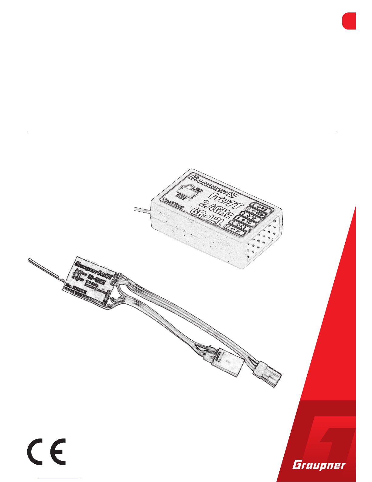
No. S1012 / S1037
GR-12L / GR-12L SUMD+T
Manual
6 channel receiver / Satellite receiver
Part 1
Page 2

Page 3

3 / 16
S1037_S1012_jh_V1
Index
Introduction ............................................................................. 4
Service Centre .......................................................................... 4
Intended use ............................................................................ 5
Package content ....................................................................... 5
Technical data .......................................................................... 5
Symbols explication ................................................................. 6
Safety notes.............................................................................. 6
Installation ............................................................................... 8
Binding ..................................................................................... 8
Connection S1012 - GR-12L ...................................................... 9
Power supply ..................................................................................9
Connection S1037 - GR-12L SUMD+T ..................................... 10
Power supply ................................................................................10
Receiver settings .................................................................... 11
Receiver settings menu ...............................................................11
Free mixers ...................................................................................12
Channel reverse ..................................................................... 13
Firmware update .................................................................... 13
Declaration of conformity ...................................................... 13
Notes on environmental protection ...................................... 14
Care and maintenance ........................................................... 14
Warranty ................................................................................ 14
Page 4
4 / 16
S1037_S1012_jh_V1
Introduction
Thank you very much for purchasing the Graupner GR-12L receiver.
This GR-12L receiver is extremely versatile.
Read this manual carefully to achieve the best results with your
GR-12L receiver and first of all to safely control your models. If you
experience any trouble during operation, take the instructions to
help or ask your dealer or
Graupner Service Centre.
Due to technical changes, the information may be changed in this
manual without prior notice. Keep updated by regularly checking
our own website,
www.graupner.de to be always updated with the
products and firmware.
This product complies with national and European legal requirements.
To maintain this condition and to ensure safe operation, you must
read and follow this user manual and the safety notes before using
the product!
NOTE
This manual is part of the product. It contains important information concerning operation and handling. Keep these instructions
for future reference and give it to third person in case you gave the
product.
Service Centre
Graupner Central Service
(+49) (0)7021/722-130
Monday - Thursday:
9:15 am - 4:00 pm
Friday:
9:15 am - 1:00 pm
Graupner USA
OPENHHOBBY LLC
3245 University Ave
Suite 1520
San Diego, CA 92104
Website: www.graupnerusa.com
Phone: +1 855-572-4746
Email:service@graupnerusa.com
Graupner in Internet For the service centers outside Germany please refer to our web site
www.graupner.de
Page 5
5 / 16
S1037_S1012_jh_V1
Intended use
The GR-12L receiver is designed exclusively to be used in bat-
tery-powered, radio controlled models, any other use is not allowed.
The GR-12L receiver works only with HoTT transmitters. For any
improper use no warranty or liability is accepted.For any improper
use no warranty or liability is accepted.
Read through this entire manual before you attempt to install or use
the GR-12L receiver.
Target group
The product is not a toy. It is not suitable for children under 14 years.
The installation and operation of the GR-12L receiver must be performed by experienced modelers. If you do not have sufficient knowledge about dealing with radio-controlled models, please contact an
experienced R/C model fan or a model club.
Package content
GR-12L receiver
Manual
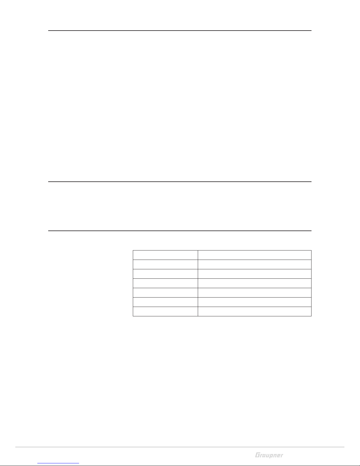
Technical data
GR-12L
Frequency band 2,4 … 2,4835 GHz
Operating voltage (2,5) 3,6...8,4 V
Range 2000 m
Power consumption 70 mA
Temperature range -15...+70°C
Dimensions 36x21x10 mm (S1037 - 25x19x5mm)
Weight 7 g (S1037 - 5 g)
Page 6

6 / 16
S1037_S1012_jh_V1
Symbols explication
!
Always observe the information indicated by this warning sign. Par-
ticularly those which are additionally marked with the CAUTION or
WARNING. The signal word WARNING indicates the potential for
serious injury, the signal word CAUTION indicates possibility of
lighter injuries.
The signal word
Note indicates potential malfunctions.
Attention indicates potential damages to objects.
Safety notes
!
These safety instructions are intended not only to protect the prod-
uct, but also for your own and other people’s safety. Therefore please
read this section very carefully before using the product!
Do not carelessly leave the packaging material lying around, since it
might become a dangerous toy for children.
Persons, including children, with reduced physical, sensory or mental capabilities, or lack of experience or knowledge, or not capable
to use safely the receiver must not use the receiver without supervision or instruction by a responsible person.
Operation and use of radio-controlled models needs to be
learned! If you have never operated a model of this type before,
start carefully and make yourself familiar with the model's reactions to the remote control commands. Proceed responsibly.
First, always perform a range and function test on the ground (to
do so, hold your model tight), before you use your model. Repeat
the test with running motor and with short throttle bursts.
Before you start using the remote control model, you have to
check the further relevant laws and regulations. These laws you
must obey in every case. Pay attention to the possibly different
laws of the countries.
Page 7

7 / 16
S1037_S1012_jh_V1
The insurance is mandatory for all kinds of model operation. If
you already have one, please inform yourself if the operation of
the respective model is covered by your insurance. If this is not
the case, conclude a special liability insurance policy for models.
We recommend to provide your model with a label, where your
personal data are indicated. So that the model can be clearly
assigned in the event of a crash.
Due to safety and licensing reasons (CE), any reconstruction and/
or modification of the product is prohibited.
Only use the components and spare parts that we recommend.
Always use matching, original Graupner plug-in connections of
the same design and material.
Make sure that all of the plug-in connections are tight. When dis-
connecting the plug-in connections, do not pull the cables.
Protect the receiver from dust, dirt, moisture and foreign parts.
It must be protected from vibration as well as excessive heat or
cold. The models may only be operated remotely in normal outside temperatures such as from -10°C to +55°C.
Only operate all your components using the current software
version.
If you have questions which cannot be answered by the operat-
ing manual, please contact us or another expert in the field.
WARNING
Also while programming, make sure that a connected electric
motor cannot accidentally start. Risk of injury by rotating propellers!
Avoid shock and pressure. Check the receiver regularly for dam-
ages to the housings and cables, specially after model crashes.
Damaged or wet receiver, even if re-dried, should no longer be
used!
!
Page 8

8 / 16
S1037_S1012_jh_V1
Installation
Install the receiver so that the connecting cables for the servos and
power supply remain loose, and so that the receiving antennas are
at least 5 cm from all large metal parts or wires. This includes carbon
fiber parts, servos, electric motors, fuel pumps, all types of cables,
etc. in addition to steel parts. It is preferable to install the receiver
away from all other installed parts at an easily accessible location in
the model. Servo cables may not be wound around antennas or run
next to them.
If the fuselages are made of carbon fiber, the ends of the antennas
should extend from the fuselage by at least 35 mm. If necessary,
exchange the approx. 145 mm standard antennas for HoTT receivers
with the 300 mm or 450 mm long antennas No. 33500.2 or 33500.3.
Binding
Binding is only possible if the receiver has not been linked with a
bound transmitter since being switched on (red LED lights). Press the
SET button to set the receiver to BIND mode.
If you wish to bind the receiver to a new model memory, this is the
procedure:
Switch the transmitter’s RF section off in the “Basic model set-
tings” menu (see transmitter manual)
Switch on the receiver and put it in binding mode, by pressing
and holding the binding button (green and red LED on the
receiver are flashing)
Initiate binding in the transmitter’s “Basic model settings” menu
If the red LED of the receiver goes out within about 10 seconds
and the green LED is illuminated, the binding process has been
completed successfully.
Your transmitter/receiver combination is now ready for opera-
tion.
If the red LED is still lit, the "binding“ failed. In this case, repeat
the whole procedure.
Page 9

9 / 16
S1037_S1012_jh_V1
Connection S1012 - GR-12L
Connect the servos to the row of sockets on one end of the receiver.
The connectors are reverse polarity protected: note the small chamfers on the sides. Never use force – the connectors should engage
easily. The polarity is also printed on the receiver; the negative wire
(-) is brown, the positive (+) red and the signal orange. The servo
sockets of Graupner-HoTT 2.4 receivers are numbered sequentially.
Attention
A servo plug must never be inserted horizontally on the vertical servo
connectors. Orientation of the servo connectors as indicated on the
receiver. Risk of short-circuit.
The socket for channel 6 can also be programmed to deliver a (digital) sum signal (see receiver settings section).
Power supply
The receiver does not feature specific sockets for connecting the
battery. We recommend that you connect the power supply to the
socket(s) close to the servos already connected to the receiver. If you
wish to connect multiple separate batteries, the batteries must be
of the same nominal voltage and capacity. Never connect different
battery types or batteries with strongly different charges since this
can cause an effect similar to a short circuit. In such cases for safety
reasons, insert voltage stabilizing elements such as PRX-5A (No.
4136) receiver power supplies between the batteries and receiver.
Attention
Never connect a battery with voltage higher than 8,4V directly to the
receiver! The receiver and the connected servos would be destroyed.
Telemetry or channel (T/5) socket
The socket is also used for channel 5
The optional telemetry sensors or modules are connected to the
socket marked “T” (T/5)- Telemetry. In addition, the update is performed on this socket. (see section Firmware update)
Page 10

10 / 16
S1037_S1012_jh_V1
Connection S1037 - GR-12L SUMD+T
Connect your Flybarless system to the SUMD connector.
You can connect HoTT sensors to the Telemetry port.
The colors of both cables mean:
brown cable (-) power supply
red cable (+) power supply
orange cable (signal) telemetry or SUMD
Power supply
You can connect the power supply to the receiver through one of the
two cables. Always use only one cable and one power supply. Make
sure that the power supply voltage is not higher than 8,4V DC.
Connection SUMD
Connection Telemetry
Antenna
Page 11

11 / 16
S1037_S1012_jh_V1
Receiver settings
The receiver can be programmed with a suitable HoTT transmitter
or in connection with the SMART-BOX.
Receiver settings menu
The receiver setup menu appears in the “Telemetry“ menu under
SETTINGS / DISPLAYS or if you are using a SMART-BOX under SETTING & DATAVIEW. How to access this menu is described in the operating instructions supplied with your transmitter or Smart-Box.
Low voltage warning (ALARM VOLT):
If the receiver voltage falls below the set value, a low-voltage warning is generated by the transmitter in the form of a "general alarm
tone" (regular beeping at a rate of approx. one beep per second) or
the "receiver voltage" speech output message.
Temperature warning (ALARM TEMP):
If the receiver temperature exceeds the set temperature, a warning
is generated by the transmitter in the form of a "general alarm tone"
(regular beeping at a rate of approx. one beep per second) or the
"receiver temperature" speech output message.
Cycle time (CYCLE):
Cycle time (PERIOD): If your system is used exclusively with digital
servos, you can set a cycle time (frame rate) of 10 ms. If your system
includes some or uses exclusively analogue servos, you should always
select 20 ms, as many analogue servos cannot process the higher
frame rate and may respond by "jittering" or "growling".
Sensor at channel 5 (K5):
The output channel 5 can be used as servo output or as telemetry
port.
HoTT sum signal at channel 6 (SUMD):
If you activate the digital sum signal at channel 6, a sum signal containing 8 channels is present at this socket, instead of a servo signal.
If the transmitter is configured as SUMD,it generates permanently
from 8 control signals of the transmitter a digital sum signal which is
emitted through the channel 6. This type of signal was being used by
several Flybarless systems and power supplies.
RECEIVER 2.0< >
>ALARM VOLT 3,8V
ALARM TEMP: 70°C
>PERIOD: 20ms
SensoratK5: No
SUMD at K6: Yes
Page 12

12 / 16
S1037_S1012_jh_V1
Free mixers
Up to five mixers can be contemporaneously programmed. You can
switch between Mixer 1, Mixer 2, 3, 4 … and mixer 5 in the “Mixer”
line.
The following settings only affect the mixer selected in this line.
FROM CHANNEL:
The signal source (or source channel) is mixed in to the target channel (TO CHANNEL) with a programmable amount. The method of
setting up the values is analogous to the “Free mixers” menu in HoTT
transmitters.
TO CHANNEL:
Part of the source channel signal (FROM CHANNEL) is mixed into the
target channel (TO CHANNEL). The mixer ratio is determined by the
percentage values entered in the “TRAVEL-” and “TRAVEL+” lines.
Select “0” if you do not require the mixer.
Mixer ratio (TRAVEL-/+): in these two lines you can define the mixer
ratio in relation to the source channel (FROM CHANNEL); the value
is set separately for both directions.
Trim
Offset value of the mixer.
Trim range: -30... 0...+30
Travel -
Settles the lowest limit for the output channel.
Range: -100...0...+100
Travel +
Settles the highest limit for the output channel.
Range: -100...0...+100
RX FREE MIXER < >
>MIXER: 1
MASTER CH: 3
>SLAVE CH: 4
>TRIM: +0%
TRAVEL-: +100%
TRAVEL+: +100%
Page 13

13 / 16
S1037_S1012_jh_V1
Channel reverse
With this option it is possible to reverse the servo direction to adapt
it to the specifics of each model.
NORMAL - normal servo direction
REVERSE - inverted servo direction
Firmware update
Updates to the receiver’s firmware are made via the output channel
5 / telemetry socket using a PC running Windows XP, Vista or 7. You
will also need a USB interface, order No. 7168.6, and adapter lead,
order No. 7168.6A or 7168.S, which are available separately.
All other information can be found in the instructions that come in
the software package.
The programs and files required can be found in the Download area
for the corresponding products at:
www.graupner.de.
Declaration of conformity
S1037 / S1012 receiver GR-12L HoTT
Graupner/SJ declares that the product is conform to EU norms.
EN 301 489-1 V1.9.2 EN 301 489-17 V2.2.1
EN 300 328 V1.8.1
EN 60950-1+A11+A1+A12+A2:2013
EN 62311:2008
CH REVERSE <
>CH1: NORMAL
CH2: NORMAL
CH3: NORMAL
CH4: NORMAL
CH5: NORMAL
CH6: NORMAL
Page 14

14 / 16
S1037_S1012_jh_V1
Notes on environmental protection
Disposal notes
This symbol on the product, user manual or packaging indicates that
this product must not be disposed of with other household waste at
the end of its life. It must be handed over to the applicable collection
point for the recycling of electrical and electronic equipment.
The materials are recyclable as marked. By recycling, material reusing or other forms of scrap usage you are making an important contribution to environmental protection.
Batteries and accumulators must be removed from the device and
disposed of at an appropriate collection point. Please inquire if necessary from the local authority for the appropriate disposal site.
Care and maintenance
Notes on care
The product does not need any maintenance, it works so as it is without any special care. In your own interests protect it from dust, dirt
and moisture.
Warranty
The Graupner, Henriettenstrassee 96, 73230 Kirchheim/Teck grants
from the date of purchase of this product for a period of 24 months.
The warranty applies only to the material or operational defects
already existing when you purchased the item. Damage due to misuse, wear, overloading, incorrect accessories or improper handling
are excluded from the guarantee. The legal rights and claims are not
affected by this guarantee. Please check exactly defects before a
claim or send the product, because we have to ask you to pay shipping costs if the item is free from defects.
The present construction or user manual is for informational purposes only and may be changed without prior notice. The current
version can be found on the Internet at
www.graupner.de on the rel-
evant product page. In addition, the company
Graupner has no
responsibility or liability for any errors or inaccuracies that may
appear in construction or operation manuals.
No liability can be accepted for printing errors.
P
Page 15

15 / 16
S1037_S1012_jh_V1
Page 16

 Loading...