

Page 1
zu Best.-Nr. 9400
BAUANLEITUNG
Elektro-UHU
Für Elektroantrieb mit 2 LiPo-Zellen
oder 6 NiMH Zellen mit 1,0Ah
Es wird eine Fernsteuerung mit 3 Funktionen benötigt
GRAUPNER GmbH & Co. KG D-73230 KIRCHHEIM/TECK GERMANY
Änderungen vorbehalten! Keine Haftung für Druckfehler! Id.-Nr. 0057535 08/2006
Page 2

Bitte unbedingt die folgenden Sicherheitshinweise beachten.
Sofern das Modell an eine andere Person weitergegeben wird, müssen diese Sicherheitshinweise,
bzw. die komplette Bauanleitung zur Beachtung weitergegeben werden.
Sicherheitshinweise
Für den Betrieb Ihres Flugmodells benötigen Sie eine gültige Haftpflichtversicherung, dies ist
vom Gesetzgeber so vorgeschrieben.
Vor dem Versuch der ersten Inbetriebnahme muss die gesamte Betriebs- bzw. Bauanleitung
sorgfältig gelesen werden. Sie alleine sind verantwortlich für den sicheren Betrieb Ihres RCFlugmodells. Bei Jugendlichen muss der Bau und Betrieb von einem Erwachsenen, der mit den
Gegebenheiten und möglichen Gefahren eines RC-Flugmodells vertraut ist, verantwortlich
überwacht werden.
Rechtlich gesehen, ist ein Flugmodell ein Luftfahrzeug und unterliegt entsprechenden
Gesetzen, die unbedingt eingehalten werden müssen. Die Broschüre »Modellflugrecht,
Paragrafen nd mehr«, Best.-Nr. 8034.01 stellt eine Zusammenfassung dieser Gesetze dar; sie
kann auch beim Fachhandel eingesehen werden. Ferner müssen postalische Auflagen, für die
Fernlenkanlage , beachtet werden. Entsprechende Hinweise finden Sie in der
Bedienungsanleitung Ihrer Fernsteueranlage.
Es dürfen nur die in dem Bausatz enthaltenen Teile, sowie die ausdrücklich von uns
empfohlenen Original-Graupner-Zubehör- und Ersatzteile verwendet werden. Wird eine
Komponente der Antriebseinheit geändert, ist ein sicherer Betrieb nicht mehr gewährleistet
und es erlischt jeglicher Garantieanspruch.
Kurzschlüsse und Falschpolungen vermeiden.
Durch die hohe Energie der Batterien besteht Explosions- und Brandgefahr.
Ein RC-Flugmodell kann nur funktionsfähig sein und den Erwartungen entsprechen, wenn es
im Sinne der Bauanleitung sorgfältigst gebaut wurde. Nur ein vorsichtiger und überlegter
Umgang beim Betrieb schützt vor Personen- und Sachschäden. Niemand würde sich in ein
Segelflugzeug setzen und - ohne vorausgegangene Schulung - versuchen, damit zu fliegen.
Erfolgreiches Modellfliegen erfordert ebenso eine Ausbildungs-bzw. Übungsphase.
Der Hersteller hat jedoch keine Möglichkeit, den Bau und den Betrieb eines RC-Flugmodells zu
beeinflussen. Deshalb wird hiermit auf die Gefahren nachdrücklich hingewiesen und jede
Haftung dafür abgelehnt.
Bitte wenden Sie sich dazu an erfahrene Modellflieger, an Vereine oder Modellflugschulen.
Ferner sei auf den Fachhandel und die einschlägige Fachpresse verwiesen. Am besten als
Club-Mitglied auf zugelassenem Modellflugplatz fliegen.
Klebstoffe enthalten Inhaltsstoffe, die unter Umständen gesundheitsschädlich sein können.
Beachten Sie daher unbedingt auch die entsprechenden Hinweise und Warnungen der
Hersteller.
Der Betreiber muss im Besitz seiner vollen körperlichen und geistigen Fähigkeiten sein. Wie
beim Autofahren, ist der Betrieb des Flugmodells unter Alkohol oder Drogeneinwirkung nicht
erlaubt.
Informieren Sie Passanten und Zuschauer vor der Inbetriebnahme über Gefahren, die von
Ihrem Modell ausgehen und ermahnen Sie diese, sich in ausreichendem Schutzabstand
aufzuhalten.
Stets mit dem notwendigen Sicherheitsabstand zu Personen oder Hindernissen fliegen, nie
Personen überfliegen oder auf sie zufliegen!
Modellflug darf nur bei Außentemperaturen von - 5º C bis + 35º C betrieben werden. Extreme
Temperaturen können zu Veränderungen der Batteriekapazität, der Werkstoffeigenschaften
sowie z. B. zu mangelhaften Klebeverbindungen u.s.w. führen.
Jeder Modellflieger hat sich so zu verhalten, dass die öffentliche Sicherheit, insbesondere
andere Personen und Sachen, sowie der Ablauf des Modellflugbetriebs nicht gefährdet oder
gestört wird.
Page 3
Das Flugmodell niemals in der Nähe von Hochspannungsleitungen, Industriegeländen, in
Wohngebieten, öffentlichen Straßen, Schulhöfen oder Spielplätzen usw. fliegen lassen.
Überprüfung vor dem Start
Vor jedem Einsatz korrekte Funktion überprüfen. Dazu den Sender einschalten, ebenso den
Empfänger. Senderantenne ausziehen, kontrollieren, ob alle Ruder in Neutrallage stehen,
einwandfrei funktionieren und seitenrichtig ausschlagen. Diese Überprüfung bei laufendem
Motor wiederholen, während ein Helfer das Modell festhält.
Beim erstmaligen Steuern eines Flugmodells ist es von Vorteil, wenn ein erfahrener Helfer bei
der Überprüfung und den ersten Flügen zur Seite steht.
Warnungen müssen unbedingt beachtet werden. Sie beziehen sich auf Dinge und Vorgänge,
die bei einer Nichtbeachtung zu schweren - in Extremfällen tödlichen Verletzungen oder
bleibenden Schäden führen können.
Luftschrauben die durch einen Motor angetrieben werden, stellen eine ständige
Verletzungsgefahr dar. Sie dürfen mit keinem Körperteil berührt werden! Eine schnell drehende
Luftschraube kann z. B. einen Finger einschneiden!
Sich niemals in oder vor der Drehebene von Luftschrauben aufhalten! Es könnte sich doch
einmal ein Teil davon oder die komplette Luftschraube lösen und mit hoher Geschwindigkeit
und viel Energie wegfliegen und Sie oder Dritte treffen, dies kann u. U. zu schweren
Verletzungen führen . Darauf achten, dass kein sonstiger Gegenstand mit einer laufenden
Luftschraube in Berührung kommt!
Die Blockierung der Luftschraube, durch irgendwelche Teile, muss ausgeschlossen sein.
Überprüfen Sie vor jeder Inbetriebnahme das Modell und alle an ihm gekoppelten Teile (z. B.
Luftschrauben, RC-Teile usw.) auf festen Sitz und mögliche Beschädigungen. Das Modell darf
erst nach Beseitigung aller Mängel in Betrieb genommen werden.
Vergewissern Sie sich, dass die verwendete Sender- Frequenz frei ist. Erst dann den Sender
einschalten! Funkstörungen, verursacht durch Unbekannte, können stets ohne Vorwarnung
auftreten! Das Modell ist dann steuerlos und unberechenbar! Fernlenkanlage nicht
unbeaufsichtigt lassen, um ein Betätigen durch Dritte zu verhindern.
Elektromotor nur einschalten, wenn nichts im Drehbereich der Luftschraube ist. Nicht
versuchen, die laufende Luftschraube anzuhalten. Elektromotor mit Luftschraube nur im
eingebauten Zustand betreiben.
Die Fluglage des Modells muss während des gesamten Fluges immer eindeutig erkennbar sein,
um immer ein sicheres Steuern und Ausweichen zu gewährleisten. Machen sich während des
Fluges Funktionsbeeinträchtigungen/Störungen bemerkbar, muss aus Sicherheitsgründen
sofort die Landung eingeleitet werden. Sie haben anderen Luftfahrzeugen stets auszuweichen.
Start- und Landeflächen müssen frei von Personen und sonstigen Hindernissen sein.
Immer auf vollgeladene Batterien achten, da sonst keine einwandfreie Funktion der RC-Anlage
gewährleistet ist.
Niemals heiß gewordene, defekte oder beschädigte Batterien verwenden. Es sind stets die
Gebrauchsvorschriften des Batterieherstellers zu beachten.
Vor jedem Flug eine Überprüfung der kompletten RC-Anlage, sowie des Flugmodells, auf volle
Funktionstüchtigkeit und Reichweite durchführen.
Dabei ist zu beachten, dass bei der Inbetriebnahme die Motorsteuerfunktion am Sender immer
zuerst in AUS-Stellung gebracht wird. Danach Sender und dann erst Empfangsanlage
einschalten, um ein unkontrolliertes Anlaufen des Elektromotors zu vermeiden. Gleichfalls gilt
immer zuerst Empfangsanlage ausschalten, danach erst den Sender.
Überprüfen Sie, dass die Ruder sich entsprechend der Steuerknüppelbetätigung bewegen.
Page 4

Nach Gebrauch die Batterie aus dem Modell nehmen und nur im entladenen Zustand für Kinder
unzugänglich, bei ca. + 5º bis + 25º C aufbewahren.
Mit diesen Hinweisen soll auf die vielfältigen Gefahren hingewiesen werden, die durch
unsachgemäße und verantwortungslose Handhabung entstehen können. Richtig und
gewissenhaft betrieben ist Modellflug eine kreative, lehrreiche und erholsame
Freizeitgestaltung.
Haftungsausschluss
Sowohl die Einhaltung der Montage- und Betriebsanleitung in Zusammenhang mit dem Modell
als auch die Bedienung und Methoden bei Installation, Betrieb, Verwendung und Wartung der
Fernsteuerungsanlagen können von der Firma Graupner nicht überwacht werden. Daher
übernimmt die Firma Graupner keinerlei Haftung für Verluste, Schäden oder Kosten, die sich
aus der fehlerhaften Verwendung und Betrieb ergeben oder in irgendeiner Weise damit
zusammenhängen.
Soweit vom Gesetzgeber nicht zwingend vorgeschrieben, ist die Verpflichtung der Firma
Graupner zur Leistung von Schadensersatz, gleich aus welchem Rechtsgrund, begrenzt auf
den Rechnungswert der an dem schadenstiftenden Ereignis unmittelbar beteiligten
Warenmenge der Firma Graupner. Dies gilt nicht, soweit die Firma Graupner nach zwingenden
gesetzlichen Vorschriften wegen Vorsatz oder grober Fahrlässigkeit unbeschränkt haftet.
Allgemeines
Das Modell Elektro- UHU ist ein kompaktes RC-Elektroflugmodell, das jedem
Modellflieger viel Flugvergnügen bereitet. Das Modell ist weitgehend vorgearbeitet,
die nachfolgend beschriebenen Bauschritte sind jedoch mit größter Sorgfalt
auszuführen, damit ein sicherer und erfolgreicher Einsatz des Modells gewährleistet
ist.
Das Fluggewicht von 650 g darf keinesfalls überschritten werden.
RC-Zubehör
Zur Steuerung des Modells sind ausschließlich FM-Fernsteueranlagen wie z. B.
X-306 bis MC 24 geeignet. Weitere Informationen über RC-Zubehörteile sind dem
Hauptkatalog FS zu entnehmen
Zum Betrieb des Modells sind nachfolgend aufgeführte Zubehörteile erforderlich:
FM Fernlenkset X-306 FM 35* Best.-Nr. 4708.261.2
• Frequenzband 35 MHz in Deutschland ausschließlich für Flugmodelle reserviert.
Empfohlene Servos*
Typ Best.-Nr. Anzahl Funktion
C 261 5125.LOSE 1 Seitenruder
C 261 5125.LOSE 1 Höhenruder
* sind im Fernlenkset Best.-Nr. 4708.261.2
enthalten.
Hinweis: Bei Best.-Nr. 9400.200 ist im Lieferumfang die komplette RC- Anlage
X- 306FM inklusive 2 Stück Servos C 261 enthalten.
Die nachfolgend aufgeführten Zubehörteile sind für den Zusammenbau und den
Betrieb des Modells erforderlich.
Ladegerät ULTRMAT 10 Best.-Nr.6410
Senderbatterie (8 Stück erforderlich) Best.-Nr.98866
Senderladekabel Best.-Nr.3423
Ladekabel mit BEC- Stecker Best.-Nr.3037
Page 5

Elektroantrieb und Zubehör
Antriebsversion
Antriebsset
Best.-Nr.
Antriebsbatterie
Best.-Nr.
Druckluftschraube
Best.-Nr.
ECO SPEED 400
PLUS 7,4V
6505
GRAUPNER 6NiMH-1000
7,2 V/1,0 Ah
98834.6ST
CAM FOLDING
PUSHPROP 14 x 10cm
1335.14.10L
Hochleistung SPEED 400
PLUS 7,4V
6505
GRAUPNER LiPo
2/1500
7,4V/1,5 Ah
7638.2
CAM FOLDING
PUSHPROP 14 x 10cm
1335.14.10L
Erforderliche Werkzeuge und Klebstoffe
Balsamesser Best.-Nr. 980
Schraubendreher Best.-Nr. 810
Sechskantschraubendreher SW 1,5 Best.-Nr.5735.1,5
Schleifpapier 120 Best.-Nr.1068.0
Mini-Stichsäge Best.-Nr.982 mit
Best.-Nr.861
Seitenschneider
Mini-Flachzange
Papierschere
Faserstift blau
Lineal mit Maßskala
Sekundenkleber Best.-Nr. 5821
Aktivator für Sekundenkleber Best.-Nr.953.150
Bauanleitung
Bitte lesen Sie vor Baubeginn die Bauanleitung durch, sodass Sie einen Überblick
über den Ablauf des Zusammenbaus erhalten. Legen Sie sich die jeweils
notwendigen Bauteile, Werkzeuge und Klebstoffe für eine Baustufe bereit . Die
Bauteile entsprechend der Bauanleitung vorbereiten.
Beim Zusammenbau immer auf eine saubere, glatte Unterlage achten oder auf einer
Schaumstoffunterlage arbeiten. Sofern nichts anderes angegeben Sekundenkleber
mit Aktivator als Klebstoff verwenden. Am besten eine Seite der Klebeverbindung mit
Klebstoff versehen und die Gegenseite mit Aktivator besprühen. Besonders darauf
achten, dass kein Restklebstoff an Ihre Hände oder auf die Oberfläche des Modells
gelangt.
Achtung: Sekundenklebstoff darf keinesfalls mit Körperteilen in Verbindung
kommen oder in Ihre Augen gelangen, wir empfehlen deshalb bei der
Anwendung eine Schutzbrille zu tragen .
Den Klebstoff für Kinder unerreichbar aufbewahren.
Verwenden Sie keinesfalls Styropor-Sekundenklebstoff , Holz-Weißleim oder
Epoxyd- Klebstoff. Mit diesen Klebstoffen wird zwischen allen Materialien und
dem SOLIDPOR- Hartschaum keine feste Klebeverbindung erzielt.
Versuchen Sie nicht das Modell mit Styropor-Sprühlack oder anderen Farben
zu lackieren, die Lacke haften nicht auf dem SOLIDPOR- Hartschaum.
Page 6

Entfernen Sie zuerst den fertigungsbedingten Grat des SOLIDPOR Fertigrumpfes.
Der Fertigungsgrat am Rumpf (1) wird abgetrennt. Verwenden Sie hierfür eine
scharfe Messerklinge.
Das CFK-Rohr (2) einkleben, achten Sie darauf, dass die Rumpfunterseite gerade
aufliegt.
Die Buchsen (3) einkleben, darauf achten, dass kein überschüssiger Klebstoff in die
Buchsen gelangt.
Page 7
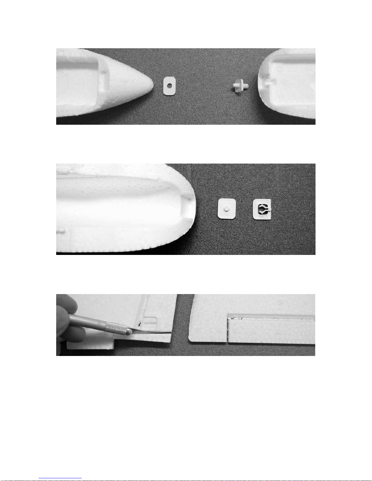
Die Dübelaufnahme (4) in die Rumpfnase einkleben, darauf achten, dass diese fest
bis zum unteren Absatz gedrückt wird, da sonst später die Kabinenhaube nicht
aufliegt. Den Dübel (5) in die Kabinenhaube (6) einkleben.
Den Halteclip (7) mit der Öffnung nach oben in den Aufsatz der Tragfläche (21)
einkleben, den Zapfen (8) in die Kabinenhaube (6) einkleben darauf achten, dass er
dabei fest nach oben gedrückt wird.
Machen Sie die Ruder von den Leitwerken (11) und (12) durch das Heraustrennen
der äußeren Fertigungsstege freigängig. Achtung, trennen Sie keinesfalls die Ruder
ab, da die dünne SOLIDPOR- Verbindung zur Dämpfungsfläche als Ruderscharnier
dient.
Hinweis: Das Seiten- und Höhenleitwerk (11) und (12) besteht jeweils aus der
Dämpfungsfläche, die später fest mit dem Rumpf (1) verklebt wird und aus dem
beweglichen Teil, das als Ruder bezeichnet wird und mittels Servo und Bowdenzug
angelenkt wird. Richtungsangaben (rechts/links) beziehen sich immer auf die Ansicht
von hinten.
Page 8
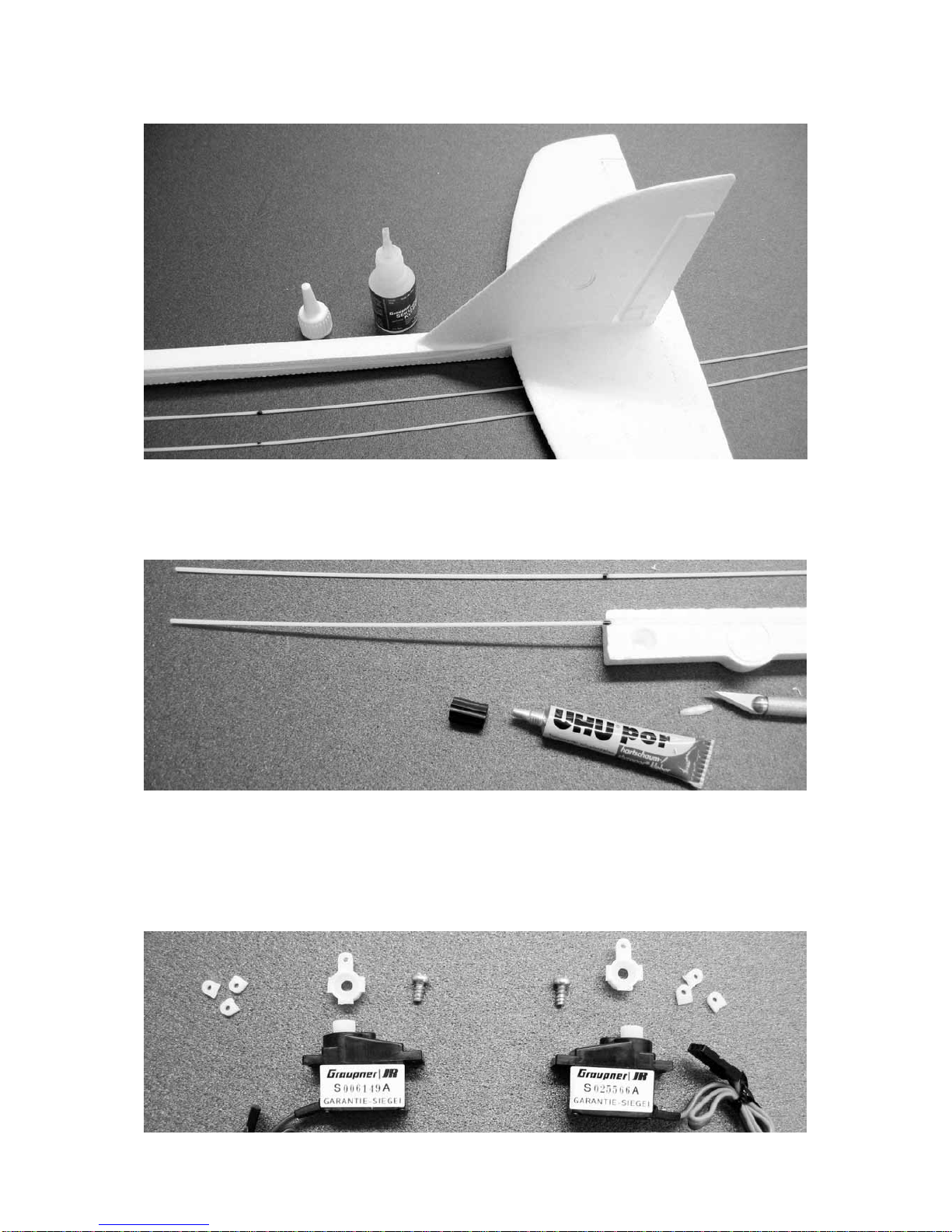
Das Seitenleitwerk (11) senkrecht auf das Höhenleitwerk (12) kleben. Die
Bowdenzugaußenrohre (9) und (10) sind gemäß der Maßangabe in der Stückliste
bereits abgelängt und liegen zum Einkleben bereit.
Die Bowdenzüge stehen vorne 195mm über, mit Faserstift markieren, dann die
Bowdenzüge mit UHU-por einkleben. Hinweis: UHU-por ist ein sogenannter
Kontaktklebstoff. Deswegen den Klebstoff in die vorhandene Nut eingeben, den
Bowdenzug eindrücken und sofort wieder herausnehmen. Wenn der Klebstoff
abgelüftet hat ( dauert ca. 5 Minuten ) die Bowdenzüge in die jeweilige Nut drücken.
Page 9
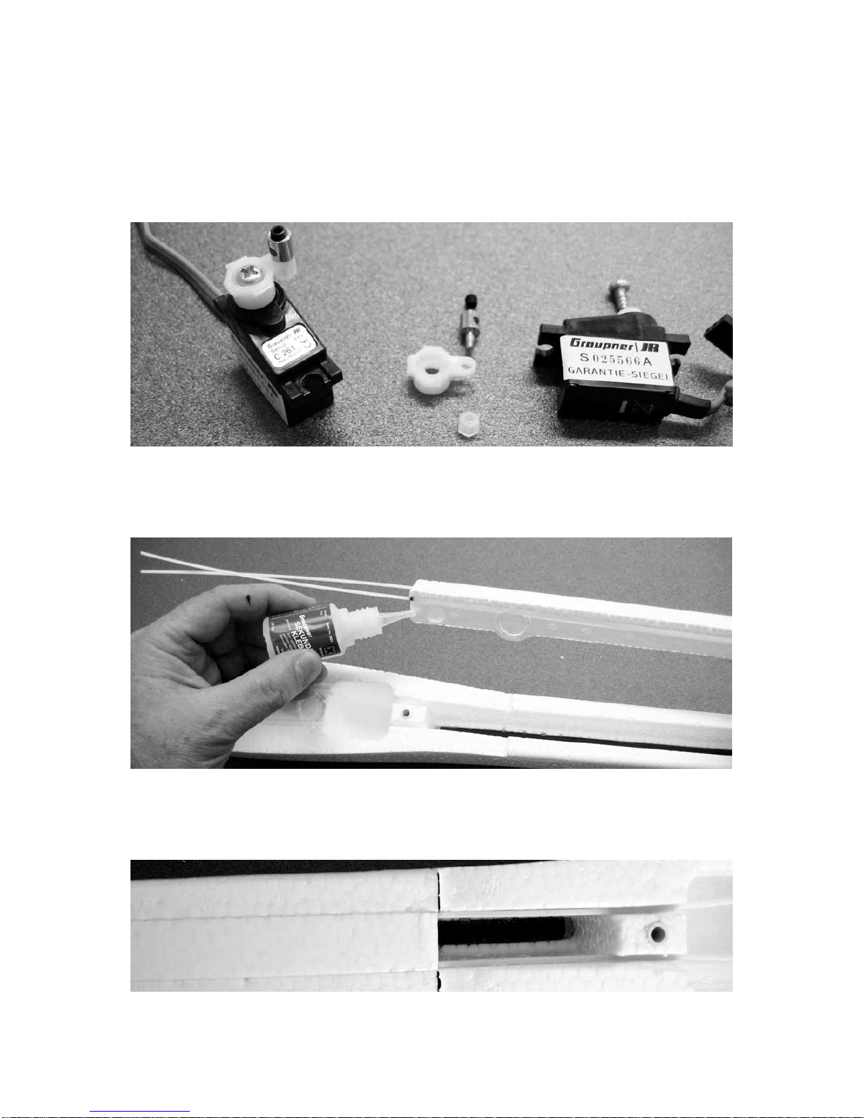
Die Servohebel abschrauben, überflüssige Schenkel mit dem Seitenschneider
abtrennen. Die Bohrung der Servohebel für die Gestängeaufnahmen (13) mit einem
Bohrer Ø 2,1mm aufbohren. Tipp: Sofern kein passender Bohrer zur Verfügung steht
kann das Loch mit der Spitze des Balsamessers jeweils von beiden Seiten passend
vergrößert werden. Das Balsamesser wird dann sozusagen als konische Reibahle
verwendet.
Die Gestängeaufnahmen (13) mittels STOP-Mutter (14) aufschrauben. Achtung,
STOP-Mutter nur soweit aufdrehen, dass sich die Gestängeaufnahme gerade noch
leicht drehen lässt.
Das bereits vorbereitete Seitenleitwerk einkleben. Achtung: In diesem
Anwendungsfall keinesfalls vorher Aktivator in den Rumpf sprühen, da sich sonst das
Leitwerk nicht passend ausrichten, bzw. verschieben lässt.
Die Vorderkante von Teil (11) muss mit der Tragflächenendkante übereinstimmen.
Page 10
Den Höhenruderzug (16) in das mittlere Loch des Ruderhornes (18) einhängen, dann
den Zug in das Bowdenzugaußenrohr (10) einschieben und jetzt erst das Ruderhorn
einkleben.
Die Installation der Seitenruderanlenkung Teile (17) und (18) erfolgt nach dem
bereits beschriebenem Prinzip, Einhängepunkt jedoch ganz außen.
Die Abbildung zeigt die fertig eingeklebten Servos. Die Ruderzüge (16) und (17)
führen durch die Gestängeaufnahmen (13) und sind per Seitenschneider abgelängt.
Page 11

Zum Festziehen der Gewindestifte Stiftschlüssel SW 1,5 und Flachzange verwenden,
darauf achten, dass vor dem Festziehen die Ruder in Mittelstellung stehen.
Wichtig: Bevor die komplettierten Servohebel wieder aufgeschraubt werden die
Servos per Fernsteuerung oder Servotester neutral ( Mittelstellung ) einstellen und
den Servohebel dann möglichst rechtwinklig zum Servo aufschieben.
Die Abbildung zeigt die vorbereiteten Einzelteile (19) bis (23)zum Einkleben in die
Tragfläche (21). Das CFK-Rohr (22) ist mit Schleifpapier überschliffen und vom
Schleifstaub befreit. Zum Einkleben der Inserts (19) die Schrauben (20) eindrehen,
somit kann die senkrechte, bzw. geradlinige Lage der Inserts geprüft werden.
Das CFK-Rohr (22) gemeinsam mit den Teilen (23) einkleben. Insbesondere zum
Einkleben der Inserts (19) ausreichend Klebstoff verwenden.
Page 12

Das Rad (26) auf den Fahrwerksbügel (24) schieben und das Achsenende per MiniFlachzange abwinkeln.
Die Abbildung zeigt den eingeschobenen Fahrwerksbügel, der mit der
Blechschraube (25) gesichert ist.
Hinweis: Die Installation der Fahrwerksteile (24) bis (30) kann, sofern gewünscht
entfallen. Der Fahrwerkseinbau ist besonders interessant, wenn die Möglichkeit zum
Starten und Landen auf einer glatten Startpiste vorhanden ist. Legen Sie Wert auf
optimale Flugleistungen und haben nur eine Rasenfläche zur Verfügung, können Sie
auf das Fahrwerk verzichten. Die Mulde in der Rumpfunterseite mit dem
entsprechenden Dekorelement (31) überkleben.
Die Abbildung zeigt die Einzelteile (27 bis 30) des Hauptfahrwerkes. Zuerst die
Radaufnahme (28) unter den Radkasten (27) kleben, dann die Einheit mit Radachse
(29) und Hauptrad (30) komplettieren.
Die komplette Hauptradeinheit in den Rumpf einkleben, darauf achten, dass kein
Klebstoff in das Radlager gelangt..
Page 13

Für die Motorzuleitungen mit einer Mini-Stichsäge eine Durchführung ausnehmen,
Stützräder für die nächsten Bauschritte eventuell wieder demontieren.
Den SPEED 400 PLUS-Antrieb entsprechend der Abbildung aufkleben. Achtung:
Unbedingt darauf achten, dass der Motor an der Vorderseite genügend tief sitzt. Die
Platine des PLUS-Drehzahlreglers darf nicht überstehen. Ebenso darauf achten,
dass der Motor von oben gesehen exakt gerade ausgerichtet ist. Die Luftschraube
erst nach den ersten Testläufen montieren.
Die Abbildung zeigt die fertig installierte RC-Empfangsanlage mit NiMH-Batterie.
Achtung: Die Empfängerbuchsenbelegung weicht von der Bedienungsanleitung der
X-306 Fernsteuerung (enthalten bei Best.-Nr. 9400.200) ab, da diese Anleitung in
Page 14

erster Linie für RC-Car Modelle konzipiert ist. Beachten Sie deswegen für Ihr neues
Modell Elektro–UHU die folgenden Bedienungshinweise.
Der RC-Einbau
Die Bauanleitung , sowie die Abbildungen beziehen sich auf die Fernsteueranlage X306 FM, werden andere Fernsteueranlagen eingebaut , so beachten Sie die
zugehörige Bedienungsanleitung.
Die Servos sind bereits im Rumpf installiert das Seitenruderservo in Buchse 1, das
Höhenruderservo in Buchse 2 und den SPEED PLUS Antrieb in Buchse 3 des
Empfängers einstecken. Die Empfängerantenne in der entsprechenden Nut durch
den Rumpf nach hinten führen.
Achtung, bevor die NiMH- bzw. LiPo-Batterie angeschlossen wird, unbedingt
zuerst den Sender einschalten und darauf achten, dass der Drehschalter des X306 Senders (Funktion 3) immer nach hinten gezogen ist (Stellung Motor aus )
Die Batterien im Sender aufladen, dann per Sender alle Funktionen überprüfen. Wird
der rechte Fernsteuerknüppel (Funktion 1) nach rechts bewegt, muss das
Seitenruder ebenfalls nach rechts ausschlagen. Wird der linke Knüppel(Funktion 2)
nach hinten gezogen, muss das Höhenruder nach oben ausschlagen. Sofern eine
Ruderfunktion nicht sinngemäß erfolgt kann über die kleinen Schiebeschalter links
unten am Sender die Servolaufrichtung umgepolt werden.
Die Ruderausschläge stimmen bei den vorgegebenen Hebellängen bei 100%
Servoausschlag. Der Höhenruderausschlag beträgt 8 mm nach oben und unten,
außen gemessen, der Seitenruderausschlag jeweils 10 mm, unten gemessen
Das Dekor
Die einzelnen Dekorelemente ausschneiden und gemäß der Abbildung auf dem
Verpackungskarton aufkleben.
Die Segmente der Kabinenhaube mit einem blauen Faserstift, der für alle
Oberflächen geeignet sein muss, bemalen.
Die Abbildung zeigt die Abdeckungen (31) und (32), die bei dem Entfall des
Fahrwerkes aufgeklebt werden.
Page 15

Auswiegen
Der Schwerpunktbereich liegt zwischen 70 und 90 mm von Tragflächenvorderkante
aus gemessen. Zur Einstellung nötigenfalls die Batterie entsprechend verschieben.
Die Schwerpunktlage wird geprüft, indem das Modell unterhalb der Tragfläche mit
zwei Fingern unterstützt wird. Das Modell soll dann waagrecht auspendeln.
Einfliegen
Das fertig gebaute Modell mit neutral eingestellten Rudern, an einem windstillen oder
schwachwindigem Tag einfliegen. Eine leicht gegen die Windrichtung abfallende
Wiese ist als Gelände optimal geeignet
Das Modell per Handstart bei laufendem Motor gegen die Windrichtung in die
Luft schieben. Die richtige Startgeschwindigkeit wird durch einige Laufschritte
erreicht. Keinesfalls das Modell vergleichbar mit einem Speerwurf nach oben
werfen. Mit dieser falschen Startart würde das Modell kurzzeitig nach oben steigen
um dann nach unten abzukippen. Eine Bruchlandung wäre die Folge. Das Modell
durch minimale Seitenruderausschläge auf einen Geradeausflug steuern. Die
Feintrimmung erfolgt über die Trimmschieber unterhalb, bzw. neben den
Steuerknüppeln. Liegt der Schwerpunkt im vorderen Bereich (70 bis 80mm) muss
das Höhenruder ca. 1mm nach oben getrimmt werden.
Das Modell vorerst mit kleinen Steuerausschlägen fliegen. Das Modell möglichst
geradlinig oder nur mit flachen Kurven fliegen. Wichtig: Durch die kurzzeitige
Betätigung des Seitenruders wird eine Kurve eingeleitet, danach das Ruder
wieder in Neutralposition bringen. Wird das Seitenruder zu lange oder zu stark
betätigt kommt das Modell in einen Spiralsturz. Die Landung exakt gegen die
Windrichtung mit abgeschaltetem Motor durchführen. Vor dem Aufsetzen die
Fluggeschwindigkeit des Modells durch dosierte Höhenruderausschläge reduzieren.
Die Landung immer gegen die Windrichtung ausführen.
Sofern eine glatte Starbahn zur Verfügung steht können mit dem Elektro-UHU,
vergleichbar mit einem manntragendem Flugzeug, Bodenstarts durchgeführt werden.
Der Start soll auch in diesem Fall genau gegen die Windrichtung erfolgen. Die
Richtungssteuerung am Boden erfolgt mit dem Seitenruder. Damit beim Anrollen das
Modell nicht nach vorne kippt, soll das Höhenruder bis zum Abheben voll gezogen
werden. Der Elektro–UHU hebt bereits nach ca. 3 Metern Rollstrecke ab.
Graupner Modellbau wünscht schöne Flüge mit dem Flugmodell >Elektro- UHU<
Page 16

Stückliste Elektro- UHU
TeilNr.
Benennung Anzahl Werkstoff
Abmessung in mm
1 Rumpf 1 SOLIDPOR Fertigteil
2 CFK- Rohr 1 CFK Ø 6/4x 450
3 Buchse 2 ABS Fertigteil
4 Dübelaufnahme 1 ABS Fertigteil
5 Dübel 1 ABS Fertigteil
6 Kabinenhaube 1 SOLIDPOR Fertigteil
7 Halteclip 1 ABS Fertigteil
8 Zapfen 1 ABS Fertigteil
9 Bowdenzugaußenrohr SR 1 Polyamid Ø 1,9/0,9x620
10 Bowdenzugaußenrohr HR 1 Polyamid Ø 1,9/0,9x655
11 Seitenleitwerk 1 SOLIDPOR Fertigteil
12 Höhenleitwerk 1 SOLIDPOR Fertigteil
13 Gestängeaufnahme 2 Stahl Fertigteil
14 STOP- Mutter 2 Polyamid M2
15 Gewindestift 2 Stahl M3x3
16 Höhenruderzug 1 Stahl Ø 0,5x700
17 Seitenruderzug 1 Stahl Ø 0,5x675
18 Ruderhorn 2 ABS Fertigteil
19 Insert 2 Polyamid M4x10
20 Senkkopfschraube 2 Polyamid M4x35
21 Tragfläche 1 SOLIDPOR Fertigteil
22 CFK- Rohr 1 CFK Ø 6/4x 390
23 Fahrwerkaufnahme 2 ABS Fertigteil
24 Fahrwerksbügel 2 Stahl Fertigteil
25 Blechschraube 2 Stahl Ø 2,2x6,5
26 Moosgummirad 2 Kunststoff Ø 20x6
27 Radkasten 1 ABS Fertigteil
28 Radaufnahme 1 ABS Fertigteil
29 Radachse 1 ABS Fertigteil
30 Hauptrad 1 Kunststoff Ø 40x15
31 Abdeckung 1 Klebefolie Zuschnitt
32 Abdeckung 1 Klebefolie Zuschnitt
33 Dekorelement 30 Klebefolie Zuschnitt
34 UHU por 1 Klebstoff 5g
Weiterhin enthalten 2 Stück Ersatz- Ruderhörner aus ABS
Ersatzteil (nicht enthalten)
Dekorbogen Best.-Nr. 9400.14
Page 17

BUILDING INSTRUCTIONS
Please be sure to read the Safety Notes printed below.
It is essential to hand over these Safety Notes and the complete Building Instructions
to the new owner if you ever dispose of this model.
Safety notes
The modeller must have valid third-party insurance for flying this model. This
is now a legal requirement in many countries.
Before you start construction it is essential to read right through these building
and operating instructions very carefully. You alone are responsible for the
safe operation of your radio-controlled model. Young persons should only be
permitted to operate this model under the instruction and supervision of an
adult who is aware of the hazards involved in this activity.
In legal terms our models are classed as aircraft, and as such are subject to
legal regulations and restrictions which must be observed at all times. Our
brochure “Modellflugrecht, Paragrafen und mehr” (Model Aviation Law, Legal
Requirements and more) is available under Order No. 8034.01, and contains a
summary of all these rules. Your local model shop should have a copy which
you can read. There are also Post Office regulations concerning your radio
control system, and these must be observed. Refer to your RC system
instructions for more details.
Be sure to use only those parts included in the kit, together with other genuine
Graupner accessories and replacement parts as recommended expressly by
us. Even if you change a single component you can no longer be sure that the
system will work reliably, and such changes also invalidate your guarantee.
Avoid short-circuits and reversed polarity.
The high energy density of rechargeable batteries involves a risk of fire and
even explosion.
A radio-controlled model aircraft can only work properly and fulfil your
expectations if it is built very carefully and in accordance with the building
instructions. If you wish to avoid injuring people and damaging property it is
essential to be careful and painstaking at all stages of building and operating
your model. Nobody would dream of climbing into a full-size glider and without appropriate training - attempting to fly it. Model flying is just such a
skill, and requires suitable training and plenty of practice.
As manufacturers we are not in a position to influence the way you build and
operate your RC model aircraft, and for this reason we deny all liability. All we
can do is expressly point out the hazards involved in this activity.
We suggest that you ask an experienced model flyer for help, or join a model
club or flight training school. Your local model shop and the specialist
magazines are excellent sources of information. If at all possible, it is always
best to join a club and fly at the approved model flying site.
Page 18

Adhesives and paints contain solvents which may be hazardous to health
under certain circumstances. Read and observe the notes and warnings
supplied by the manufacturer of these materials.
The operator of the model must be in full possession of his or her bodily and
mental faculties. As with car driving, operating a model aircraft under the
influence of alcohol or drugs is not permissible under any circumstances.
If there are passers-by or spectators at your flying site, make sure that they are
aware of the dangers inherent in your activity, and insist that they keep a safe
distance away.
Always keep a reasonable distance away from people and objects when flying;
never fly low over people’s heads, and never fly directly towards them.
Radio-controlled models should only be flown in “normal” weather conditions,
i.e. a temperature range of -5° to +35° C. More ext reme temperatures can lead
to changes in battery capacity and material characteristics, weakened glued
joints and other unwanted effects.
All model flyers should behave in a way that minimises the danger to people
and property. Never act in any manner which will disturb other flyers and
jeopardise safe, orderly flying at the site.
Never operate your model aircraft close to high-tension overhead cables,
industrial sites, residential areas, public roads, squares, school playgrounds,
public parks or sports grounds etc.
Pre-flight checks
Check that all the working systems are operating correctly before every flying
session: switch on the transmitter, followed by the receiver. Extend the
transmitter aerial fully, and check that all the control surfaces are exactly at
centre (neutral) when the sticks and trims are central. Ensure that the control
surfaces deflect in the correct direction. Repeat the check with the motor
running, while a friend holds the model firmly for you.
If you have not flown a model aircraft of this type before, we strongly
recommend that you ask an experienced modeller to check the aeroplane and
stand by your side during the first few flights.
Don’t ignore our warnings. They refer to materials and situations which, if
ignored, can result in fatal injury or permanent damage.
Propellers and other rotating parts which are powered by a motor constitute a
permanent hazard and represent a real risk of injury. Don’t touch them with any
part of your body. For example, a propeller spinning at high speed can easily
cut your finger badly.
Keep well clear of the rotational plane of the propeller. You never know when
some part may come loose and fly off at high speed, hitting you or anybody
else in the vicinity. Never touch the revolving propeller with any object.
Page 19

Ensure that it is impossible for any object to stall or block the propeller.
Every time you intend to operate your model check carefully that it and
everything attached to it (e.g. propeller, RC components etc.) is in good
condition and undamaged. If you find a fault, do not fly the model until you
have corrected it.
Satisfy yourself that your frequency is vacant before you switch on. Radio
interference caused by unknown sources can occur at any time without
warning. If this should happen, your model will be uncontrollable and
completely unpredictable. Never leave your radio control system unguarded,
as another person might pick it up and try to use it.
Do not switch on the electric motor unless you are sure that there is nothing in
the rotational plane of the propeller. Never attempt to stop the spinning
propeller. Electric motors with the propeller attached should only be run when
firmly mounted.
If you are to fly your model safely and avoid problems, it is essential that you
are aware of its position and attitude throughout each flight - so don’t let it fly
too far away! If you detect a control problem or interference during a flight,
immediately land the model to prevent a potential accident. Models must
always give way to full-size aircraft. Take-off and landing strips should be kept
free of people and other obstacles.
Your RC system can only work reliably if the batteries are kept fully charged.
Never use batteries which are hot, faulty or damaged. At all times heed the
instructions provided by the battery manufacturer.
Before each flight check that all functions on the model aircraft are working
correctly, and that the radio control system is in good order and operating at
full range.
Note that the motor control (throttle) function on the transmitter must always
be moved to the OFF position as the first stage in preparing for a flight. To
avoid the danger of the electric motor bursting into life unexpectedly, always
switch on the transmitter first, and only then the receiving system. The
opposite applies at the end of a flight: always switch off the receiving system
first, and finally the transmitter.
Check that the control surfaces follow the movement of the transmitter sticks.
After each flying session remove the battery from the model, check that it is
discharged, and store it in a safe place, well out of the reach of children, at a
temperature of around +5° to +25°C.
Please don’t misunderstand the purpose of these notes. We only want to make
you aware of the many dangers and hazards which can arise if you work
carelessly or irresponsibly. If you take reasonable care, model flying is a highly
creative, instructive, enjoyable and relaxing pastime.
Liability exclusion
Page 20

As manufacturers we have no control over the way you build and operate your
RC model aircraft, nor how you install, operate and maintain the associated
components, and for this reason we are obliged to deny all liability for loss,
damage or costs which are incurred due to the incorrect use of our products or
due to incompetent behaviour on the part of the user, or which are connected
with such operation in any way.
Unless otherwise prescribed by binding law, the obligation of the GRAUPNER
company to pay compensation, regardless of the legal argument employed, is
limited to the invoice value of that quantity of GRAUPNER products which was
immediately and directly involved in the event which caused the damage. This
does not apply if GRAUPNER is found to be subject to unlimited liability
according to binding legal regulation on account of deliberate or gross
negligence.
Introduction
The Elektro-UHU is a compact electric-powered RC model aircraft which is capable
of giving hours of flying pleasure to any model flyer. The machine is very highly prefabricated, but please carry out the procedures described in these instructions with
the greatest care, as this will ensure that the model will be safe to fly and have an
excellent performance.
The maximum all-up weight is 650 g, and this must not be exceeded.
RC system
This model should only be flown with an FM radio control system such as the X-306
to mc-24. Please refer to the main Graupner FS catalogue for more information on
RC system components.
You will need the following items to fly the model:
X-306 FM 35* radio control set Order No. 4708.261.2
* In Germany the 35 MHz band is reserved exclusively for model aircraft.
Recommended servos*
Type Order No. No. off Function
C 261 5125.LOSE 1 Rudder
C 261 5125.LOSE 1 Elevator
* Included in the radio control set, Order No. 4708.261.2
Note: Order No. 9400.200 includes the complete X-306 FM RC system, complete
with two C 261 servos.
The following accessories are required to operate the model:
ULTRAMAT 10 battery charger Order No. 6410
Dry cells for transmitter (eight required) Order No. 98866
Transmitter charge lead Order No. 3423
Charge lead with BEC connector Order No. 3037
Electric power system and accessories
Power
version
Power set
Order No.
Flight battery
Order No.
Pusher propeller
Order No.
Page 21

ECO SPEED 400
PLUS 7.4V
6505
GRAUPNER 6-NiMH-1000
7.2 V / 1.0 Ah
98834.6ST
CAM FOLDING
PUSHPROP 14 x 10cm
1335.14.10L
Highperformance
SPEED 400
PLUS 7.4V
6505
GRAUPNER LiPo 2/1500
7.4 V / 1.5 Ah
7638.2
CAM FOLDING
PUSHPROP 14 x 10cm
1335.14.10L
You will need the following tools and adhesives to complete the model:
Balsa knife Order No. 980
Screwdriver Order No. 810
Allen key, 1.5 mm A/F Order No. 5735.1,5
Abrasive paper, 120-grit Order No. 1068.0
Mini fine-nose saw Order No. 982 with
Order No. 861
Side-cutters ----Mini flat-nose pliers ----Paper scissors ----Felt-tip pen, blue ----Metric ruler ----Cyano-acrylate adhesive (“cyano”) Order No. 5821
Cyano-acrylate activator Order No. 953.150
Building instructions
Please read right through these building instructions before you commence
construction, so that you have a clear idea how the aeroplane goes together before
you start work. Make sure you have all the components, tools and adhesives required
for each stage of construction before you start. Some kit components need
preparation before they are fitted; this is always stated in the instructions.
When assembling the model always work on a clean, perfectly flat surface; a sheet of
foam is a good method of avoiding damage to the model surfaces. Unless specifically
stated otherwise, use cyano-acrylate and the associated activator as adhesive
throughout construction. It is best to apply the cyano glue to one surface, then spray
activator on the mating surface before joining the parts. Take particular care to avoid
glue getting onto your hands or on the finished surfaces of the model.
Caution: it is essential to avoid cyano adhesive making contact with your skin,
and with your eyes in particular. We recommend that you wear protective
goggles.
Store adhesives well out of the reach of children.
Do not use Styrofoam cyano-acrylate (“foam cyano”) for this model, nor white
glue (wood glue) or epoxy resins. None of these adhesives will produce a
strong bond between the rigid SOLIDPOR foam and other materials.
Please don’t attempt to paint the model using Styrofoam spray cans or other
types of paint; these materials will not adhere properly to the rigid SOLIDPOR
foam.
The moulding process produces “flash” - excess material at the mould joints; carefully
remove the unwanted foam from the ready-made SOLIDPOR fuselage.
Page 22

Removing the flash from the fuselage (1) using a sharp balsa knife.
Glue the carbon fibre tube (2) in the fuselage, taking care to keep the underside of
the fuselage perfectly straight (resting on the building board).
Glue the bushes (3) in the fuselage, taking care to avoid excess glue running inside
them.
Glue the dowel support (4) in the fuselage nose; take care to press it down to the
bottom of the recess, otherwise the canopy will not fit properly. Glue the dowel (5) in
the canopy (6).
Glue the retaining clip (7) in the recess in the wing (21), with the open end facing up.
Glue the lug (8) in the canopy (6), pressing it firmly into place.
The next step is to cut through the linking pieces at the ends of the rudder and
elevator (attached to the fin (11) and tailplane (12)), to allow them to deflect freely.
Caution: on no account cut off the control surfaces, as the thin line of SOLIDPOR left
at the pivot axis acts as the control surface hinge.
Note: the fin (11) and tailplane (12) each consist of a fixed portion - which is later
glued permanently to the fuselage (1) - and a moving control surface. Each of the
control surfaces is actuated by a servo and “snake” linkage. Directions (such as right
or left) always refer to the model as seen from the tail, looking forward.
Glue the fin (11) to the tailplane (12), keeping it exactly vertical. Cut the snake outer
sleeves (9) and (10) to the exact lengths stated in the Parts List. In the picture they
are shown ready to install.
The snake outers project by 195 mm at the front; mark this point, then glue the
sleeves in the fuselage using UHU-por. Note: UHU-por is a type of glue known as a
contact adhesive. For this reason you should apply the glue along the channel in the
fuselage, press the snake sleeve into it, then remove it again immediately. Allow the
glue to air-dry (this takes about five minutes), then press the sleeve into the channel
again.
Unscrew the servo output levers and cut off the unwanted arms using side-cutters.
Locate the hole in the output levers for the swivel pushrod connectors (13) and drill
them out to 2.1 mm Ø. Tip: if you don’t have the correct size of drill bit, enlarge the
hole using the tip of a pointed balsa knife, working from both sides; the balsa knife
works quite well as a make-shift tapered reamer.
Fit the swivel pushrod connectors (13) in the holes and secure them with the selflocking nuts (14). Caution: don’t over-tighten the nuts; the pushrod connectors should
be just free enough to swivel smoothly.
Page 23

The prepared tail assembly can now be glued to the fuselage. Caution: in this case
you must not spray activator in the fuselage beforehand, as this would prevent you
adjusting the position of the tailplane.
Note that the front edge of the fin (11) must line up with the trailing edge of the wing.
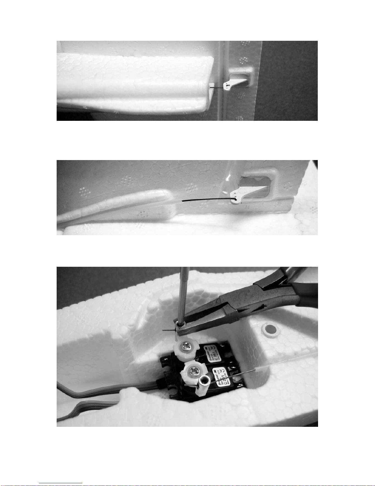
Connect the elevator pushrod (16) to the centre hole in the elevator horn (18), then
slip the pushrod into the snake outer sleeve (10). Position the horn on the underside
of the elevator, and glue it in place.
The rudder linkage, consisting of parts (17) and (18), is installed in the same manner,
except that the outermost hole in the horn should be used.
The picture shows the servos glued in the fuselage. The pushrods (16) and (17) run
through the swivel pushrod connectors (13); cut them to length using the side-cutters.
Use a 1.5 mm A/F allen key and flat-nose pliers to tighten the grubscrews in the
swivel connectors. Remember to set the rudder and elevator exactly to centre before
tightening the screws.
Important: set the servos to centre from the transmitter (or use a servo tester) before
fitting the output arms on the servo shafts. If possible, fit the output arms at 90° to the
long side of the servo cases.
The picture shows the prepared parts (19) to (23), ready for gluing in the wing (21).
Sand the carbon fibre tube (22) overall, then remove all traces of sanding dust. To
glue the threaded inserts (19) in place, fit the screws (20) in them first, as this allows
you to check that they are exactly vertical and parallel.
Glue the carbon fibre tube (22) in place at the same time as the plastic undercarriage
supports (23). Be sure to use plenty of adhesive when installing the threaded inserts
(19).
Fit the foam support wheels (26) on the undercarriage legs (24), and use mini flatnose pliers to bend the ends over to retain the wheels.
The picture shows one undercarriage leg fitted in the support and secured with the
self-tapping screw (25).
Note: if you wish, you can omit the undercarriage components (24) to (30). The
undercarriage installation is of particular interest if you have access to a smooth takeoff strip for take-off and landing. If you are looking for best possible performance, and
only have a grass flying field, the undercarriage is not really necessary. In this case
apply the decal (31) over the wheel recess in the underside of the fuselage.
The picture shows the main undercarriage components (27 to 30). Start by gluing the
wheel support 28 to the underside of the wheel box (27), then complete the assembly
with the wheel axle (29) and the main wheel (30).
Glue the complete main wheel assembly in the fuselage, taking care to avoid glue
running into the wheel bearing.
Page 24

Use a mini fine-nose saw to cut a tunnel in the motor pylon for the motor cables. We
recommend that you remove the support wheels before tackling the next stage.
Glue the SPEED 400 PLUS motor unit in place as shown in the illustration. Caution:
ensure that the front end of the motor is mounted low enough: the circuit board of the
PLUS speed controller should not project above the line of the pylon. Take care also
to align the motor exactly “straight ahead” when viewed from above. Don’t fit the
propeller until you have completed the initial motor test-runs.
The picture shows the RC receiving system and NiMH battery installed in the
fuselage. Caution: the receiver socket sequence is not as described in the operating
instructions supplied with the X-306 (included in Order No. 9400.200), since the
standard instructions are primarily intended for RC model cars. For this reason
please observe the following operating notes which apply to your new Elektro-UHU
model aircraft.
14]
RC installation
The building instructions and the pictures refer to the X-306 FM radio control system.
If you are fitting different RC equipment, please refer to the operating instructions
supplied with the set.
You have already installed the servos in the fuselage. Connect the rudder servo to
receiver socket 1, the elevator servo to socket 2, and the SPEED PLUS motor unit to
socket 3. Press the receiver aerial into the channel provided, and run it to the tail of
the model.
Caution: the next step is to test the power system, but be sure to switch the
transmitter on first, and check that the rotary switch on the X-306 transmitter
(function 3) is in the “back” position (corresponding to motor OFF) before you
connect the NiMH or LiPo flight battery.
Charge up the batteries in the transmitter, then check all the working systems from
the transmitter: move the right-hand transmitter stick (function 1) to the right, and the
rudder should also deflect to the right (as seen from the tail). If you pull the left-hand
stick (function 2) back towards you, the elevator should deflect up. If either control
system works the wrong way round, operate the appropriate small slide-switch at
bottom left on the transmitter to reverse the direction of servo rotation.
The control surface travels will automatically be correct provided that you have used
the stated lever lengths and set the servo travels to 100%. The elevator travel should
be 8 mm up and 8 mm down, measured at the outboard end. The rudder travel
should be 10 mm to either side of neutral, measured at the bottom.
Decals
Cut out the individual decals and apply them to the model in the arrangement shown
in the illustration.
Colour the canopy using a blue felt-tip pen, leaving the frame area white. Check that
the ink does not affect the foam before applying it.
The illustration shows the undercarriage decals (31) and (32) which are applied to the
wing and fuselage if the undercarriage is not fitted.
Page 25

Balancing
The Centre of Gravity should be within the range 70 to 90 mm aft of the wing root
leading edge; if necessary, adjust the position of the receiver battery until this is the
case. Check the CG by supporting the model under the wing roots on two fingertips;
it should then balance level.
Test-flying
For test-flying please wait for a day with flat calm conditions, or no more than a very
gentle breeze. A grassy meadow with a gentle slope facing directly into wind is ideal.
Assemble the model completely, ready to fly, and check that the control surfaces are
at neutral.
Give the model a hand-glide by pushing it forward directly into any breeze, with
the wings level and the nose inclined slightly down. Trot forward for a few
steps to gain sufficient launch speed. On no account throw the model upward as if
it were a javelin. If you do, the model will climb briefly, then stall and return to earth
very abruptly, usually suffering damage in the process. If necessary, the model
should be trimmed for straight flight by applying very slight rudder correction. Fine
trimming is carried out by adjusting the trim sliders located below and adjacent to the
transmitter sticks. If you have set the CG to the forward end of the range (70 to 80
mm) you will need to trim the elevator up by about 1 mm.
Start by flying the model with small control deflections. Keep the machine flying in
straight lines as far as possible, and keep all turns broad and flat initially. Important:
the procedure for turning the model is to apply rudder for a moment to initiate
the turn, then neutralise the stick again. If you hold the rudder over for too
long, or with too great a deflection, the turn will tighten up and degenerate into
a spiral dive. Land the model exactly into wind with the motor stopped, and reduce
its airspeed just before touch-down by applying gentle up-elevator. Always land
directly into wind!
If you have access to a smooth take-off strip, you can allow the Elektro-UHU to take
off from the ground, just like a full-size aeroplane. Once again you must take off
exactly into wind. The rudder is used to keep the model on course on the ground.
There will be a tendency for the model to tip forward on the take-off run, but you can
prevent this by applying full up-elevator while it is gathering speed. The Elektro-UHU
takes off after a ground-roll of about three metres.
All of us at GRAUPNER Modellbau wish you many fine flights with your new model,
the >Elektro-UHU<.
Page 26

Parts List - Elektro-UHU
Part Description No. off Material Dimensions in
mm
1 Fuselage 1 SOLIDPOR Ready made
2 Carbon fibre tube 1 CFRP 6 / 4 Ø x 450
3 Bush 2 ABS Ready made
4 Dowel support 1 ABS Ready made
5 Dowel 1 ABS Ready made
6 Canopy 1 SOLIDPOR Ready made
7 Retaining clip 1 ABS Ready made
8 Lug 1 ABS Ready made
9 Snake outer sleeve, rudder 1 Nylon 1.9 / 0.9 Ø x 620
10 Snake outer sleeve, elevator 1 Nylon 1.9 / 0.9 Ø x 655
11 Fin 1 SOLIDPOR Ready made
12 Tailplane 1 SOLIDPOR Ready made
13 Swivel pushrod connector 2 Steel M2
14 Self-locking nut 2 Nylon M2
15 Grubscrew 2 Steel M3 x 3
16 Elevator pushrod 2 Steel 0.5 Ø x 700
17 Rudder pushrod 2 Steel 0.5 Ø x 675
18 Control surface horn 2 ABS Ready made
19 Threaded insert 2 Nylon M4 x 10
20 Countersunk screw 2 Nylon M4 x 35
21 Wing 1 SOLIDPOR Ready made
22 Carbon fibre tube 1 CFRP 6 / 4 Ø x 390
23 Undercarriage support 2 ABS Ready made
24 Undercarriage unit 2 Steel Ready made
25 Self-tapping screw 2 Steel 2.2 Ø x 6.5
26 Foam rubber wheel 2 Plastic 20 Ø x 6
27 Wheel box 1 ABS Ready made
28 Wheel support 1 ABS Ready made
29 Wheel axle 1 ABS Ready made
30 Main wheel 1 Plastic 40 Ø x 15
31 Undercarriage decal 1 Self-adhesive film Oversize
32 Undercarriage decal 1 Self-adhesive film Oversize
33 Decal 30 Self-adhesive film Oversize
34 UHU por 1 Adhesive 5 g
The kit also includes two spare ABS control surface horns.
Replacement part (not included)
Decal sheet 9400.14
Page 27

INSTRUCTIONS DE MONTAGE
Avant la première lise en service, les instructions de montage et d’utilisation
devront être entièrement lues. Observer impérativement les conseils de
sécurité donnés ci-dessous.
Ces instructions devront être soigneusement conservées et remises à
l’utilisateur suivant en cas de vente du modèle.
Conseils de sécurité
Vous êtres seul responsable de la sécurité d’utilisation de votre modèle volant
R/C. Les jeunes modélistes devront effectuer le montage et utiliser ce modèle
sous la surveillance d’un adulte familiarisé avec les particularités et les
dangers d’un modèle volant R/C peut présenter.
Demandez à votre revendeur les précautions à prendre pour l’utilisation d’un
modèle volant R/C, il vous renseignera volontiers.
Un modèle volant R/C est comparable à un véritable aéronef pour lequel toutes
les dispositions légales doivent être prises. ; la possession d’une assurance
est obligatoire. Observez également les conseils correspondants donnés dans
les instructions d’utilisation de votre ensemble R/C.
Il conviendra d'utiliser exclusivement les éléments fournis dans la boite de
construction ainsi que les accessoires d'origine Graupner et les pièces
détachées conseillées. Si un seul composant de la propulsion est remplacé,
une parfaite sécurité de fonctionnement de peut plus être assurée et peut
entraîner la perte du bénéfice de la garantie.
Evitez les court circuits et les inversions de polarité.
En raison de la forte énergie emmagasinée par les batteries, il existe un danger
d’explosion et d’incendie ; c’est pourquoi il conviendra d’observer les conseils
de sécurité joints aux batteries.
Un modèle volant R/C ne peut évoluer correctement que s'il a été construit et
réglé conformément aux instructions de montage et seule une utilisation
prudente et responsable évitera de provoquer des dommages matériels ou
corporels. Personne ne peut prétendre prendre place dans un avion de
tourisme et le piloter sans un apprentissage préalable ; le pilotage sûr d’un
modèle réduit n’est possible qu’après un entraînement ou un écolage
appropriés.
Le fabricant n’au cependant aucune possibilité d’influencer la construction et
l’utilisation d’un modèle volant R/C. C’est pourquoi nous ne pouvons qu’avertir
sur les dangers présentés en dégageant toute responsabilité.
Faites-vous assister par un modéliste expérimenté, ou inscrivez-vous dans une
association ou dans une école de pilotage. Consultez pour cela votre
revendeur et la Presse spécialisée. Le mieux est de faire partie d'un club
d'aéromodélisme pour pouvoir voler sur un terrain autorisé.
Les colles contenant un solvant peuvent être dans certaines circonstances
nocives pour la santé. Observez absolument les conseils correspondants et les
avertissements du fabricant.
Page 28

L'utilisateur doit être en pleine possession de ses facultés physiques et
mentales. Comme pour la conduite des automobiles, le pilotage des modèles
volants sous l'effet de l'alcool ou de la drogue n'est pas autorisé.
Avant de faire voler votre modèle, informez les passants et les spectateurs des
dangers qu’il peut présenter et priez-les de se tenir à une distance de sécurité
suffisante du champ de rotation de l’hélice
Volez à une distance de sécurité suffisante des personnes ou des obstacles,
ne survolez jamais de personnes à basse altitude ou ne volez jamais dans leur
direction !
Un modèle volant doit être utilisé uniquement sous des températures
extérieures comprises entre – 5° C et + 35° C. Des températures extrêmes
peuvent modifier la capacité des batteries, les propriétés des matériaux ainsi
que la résistance des collages, etc…
Chaque modéliste doit se comporter de façon à ce que l'ordre et la sécurité
publique, vis-à-vis des autres personnes et des biens, ainsi que l'activité des
autres modélistes ne soient pas mis en danger, ni perturbés.
Ne faites jamais voler votre modèle à proximité des lignes à haute tension,
dans les zones industrielles, les agglomérations, sur les voies publiques, les
places, dans les cours d'école, les parcs et les aires de jeux, etc…
Les hélices et en général toutes les pièces mécaniques entraînées par un
moteur présentent un danger de blessures permanent et ne doivent être
touchées par aucune partie du corps! Une hélice tournant à haut régime peut
par ex. couper un doigt!
Ne vous tenez jamais dans le champ de rotation d'une hélice! Une pièce peut
se détacher et être éjectée à haute vitesse avec une forte inertie et vous
toucher, ou une tierce personne. Veillez également à ce qu'aucun objet
quelconque vienne en contact avec l'hélice en rotation.
Le blocage de l’hélice par un objet quelconque doit absolument être exclu.
Veillez également aux vêtements flottants tels qu’écharpe, manches de
chemise, etc.. qui peuvent être aspirés et s’enrouler autour de l’hélice.
Avant chaque utilisation, vérifiez le modèle et toutes les pièces qui y sont
rattachées (par ex. hélice, éléments R/C, etc…) pour détecter une possible
détérioration. Ce n'est qu'après avoir remédié à tous les défauts éventuels que
le modèle pourra être mis en vol.
Assurez-vous que la fréquence que vous utilisez est libre avant de mettre votre
émetteur en contact! Une perturbation peut toujours se produire pour une
cause inconnue, sans prévenir! Le modèle devient alors incontrôlable et livré à
lui-même! Ne laissez pas votre émetteur sans surveillance pour éviter une
manipulation par un tiers.
Page 29

Ne mettez le moteur électrique en contact que lorsque rien ne se trouve dans le
champ de rotation de l’hélice. Faites tourner le moteur électrique avec l’hélice
montée uniquement lorsqu’il est solidement fixé dans le modèle.
La position du modèle doit être nettement identifiable durant tout le vol pour
garantir un pilotage sûr. Si vous remarquez l'influence d'une perturbation
durant le vol, préparez-vous immédiatement à atterrir pour des raisons de
sécurité. Durant le départ et le processus d'atterrissage, le terrain doit être
libre de toute personne et d'obstacle.
Veillez toujours au bon état de charge des accus, car autrement le parfait
fonctionnement de l’ensemble R/C ne peut être garanti
N’utilisez jamais de batteries échauffées, défectueuses ou détériorées. Observez les
prescriptions d’utilisation indiquées par le fabricant des batteries.
Avant chaque vol, effectuez une vérification complète du bon fonctionnement
de l’installation R/C ainsi que du modèle et faites un essai de portée.
Pour faire un essai de fonctionnement du moteur, assurez-vous d’abord que
l’organe de commande soit sur la position COUPE sur l’émetteur. Mettez
ensuite d’abord l’émetteur en contact, ensuite la réception pour éviter un
démarrage involontaire du moteur. Procédez inversement pour couper le
contact ; d’abord celui de la réception, ensuite celui de l’émetteur.
Vérifiez si les gouvernes se déplacent dans le sens correspondant des
manches de commande.
Ces conseils mettent en évidence la diversité des dangers pouvant résulter
d'une manipulation incorrecte et irresponsable. Leur observation permettra de
pratiquer en toute sécurité ce loisir créatif et éducatif que représente
l'aéromodélisme
Exclusion de responsabilité
Vous avez fait l'acquisition d'une boite de construction avec les accessoires
correspondants qui vont vous permettre la réalisation d'un modèle radiocommandé.
Le respect des instructions de montage et d'utilisation relatives au modèle ainsi que
l'installation, l'utilisation et l'entretien des éléments de son équipement ne peuvent
pas être surveillés par la Firme GRAUPNER. C'est pourquoi nous déclinons toute
responsabilité concernent les pertes, les dommages ou les coûts résultants d'une
mauvaise utilisation ou d'un fonctionnement défectueux. Tant qu'elle n'y a pas été
contrainte par le législateur, la responsabilité de la Firme GRAUPNER n'est
aucunement engagée pour les dédommagements (incluant les dégâts personnels,
les cas de décès, la détérioration de bâtiments ainsi que le remboursement des
pertes commerciales dues à une interruption d'activité ou à la suite d'autres
conséquences directes ou indirectes) provenant de l'utilisation du modèle.
L'ensemble de sa responsabilité est en toutes circonstances et dans chaque cas
strictement limité au montant que vous avez réellement payé pour ce modèle.
Généralités
L’Elektro UHU est un modèle R/C compact à propulsion électrique dont les vols
procureront beaucoup de plaisir à son pilote. Ce modèle est largement préfabriqué,
cependant les stades de montage décrits à la suite devront être effectués avec un
grand soin pour garantir les meilleures performances du modèle.
Page 30

Un poids en ordre de vol de 650 g. ne devra en aucun cas être dépassé.
Equipement R/C
Les ensembles R/C FM comme par ex. X-306 à mc-24 sont exclusivement adaptés
pour l’équipement de ce modèle. D’autres informations sur les accessoires R/C se
trouvent dans le catalogue général FS.
Les accessoires indiqués ci-dessous sont nécessaires pour l’équipement du modèle :
1 Ensemble X-306 FM 35 MHz * Réf. N°4708.261.2
* Bande de fréquences autorisée en Almange.
Servos conseillés *
Type Réf. N° Qté Fonction
C 261 5125.LOSE 1 Direction
C 261 5125.LOSE 1 Profondeur
* Fournis avec l’ensemble R/C Réf. N°4708.261.2
Note : L’ensemble R/C complet X-306 FM incluant 2 servos C 261 est fourni
dans la Réf. N°9400.200.
Accessoires R/C :
Chargeur ULTRAMAT 10 Réf. N°6410
Batteries d’émission (8 pièces nécessaires) Réf. N°98866
Cordon de charge pour émetteur Réf. N°3423
Cordon de charge avec prise BEC Réf. N°3037
Propulsion électrique et accessoires
Version de
propulsion
Groupe de
propulsion
Réf. N°
Batterie de
propulsion
Réf. N°
Hélice propulsive
Réf. N°
ECO SPEED 400 PLUS
7,4 V
6505
GRAUPNER 6NiMH1000 7,2 V/1,0 Ah
98834.6ST
CAM FOLDING
PUSHPROP 14x10
cm
1335.14.10L
Haute puissance SPEED 400 PLUS
7,4 V
6505
GRAUPNER LiPo
2/1500 7,4/1,5 Ah
7638.2
CAM FOLDING
PUSHPROP 14x10
cm
1335.14.10L
Outils et colles nécessaires
Couteau à balsa Réf. N°980
Tournevis Réf. N°810
Tournevis six pans SW 1,5 Réf. N°5735.1,5
Papier abrasif grain 120 Réf. N°1068.0
Mini scie trou de serrure Réf. N°982 avec
Réf. N°861
Pinces coupantes
Mini pinces plates
Ciseaux
Page 31

Crayon feutre bleu
Réglet métallique gradué
Colle-seconde Réf. N°5821
Activateur pour colle-seconde Réf. N°953.150
Instructions de montage
Veuillez lire entièrement ces instructions avec de commencer le montage afin d’avoir
un aperçu sur le déroulement des assemblages. Tenez prêt chaque pièce, outil et
colle nécessaires pour un stage de montage ; préparez les pièces conformément aux
instructions de montage.
Pour effectuer les assemblages, travailler toujours sur une surface propre ou sur une
base en caoutchouc mousse. Tant qu’une autre indication n’est pas donnée, utilisez
de la colle-seconde avec de l’activateur. Le mieux est d’appliquer la colle sur une
surface du collage à effectuer et de vaporiser de l’activateur sur la surface opposée.
Veillez particulièrement à ce que la colle ne coule pas sur vos mains ou sur les
surfaces du modèle.
Attention : La colle-seconde ne doit en aucun cas entrer en contact avec les
parties du corps ou avec vos yeux, pour cette raison nous vous conseillons de
porter des lunettes de protection.
La colle devra être conservée hors de la portée des enfants.
N’utilisez en aucun cas de la colle-seconde pour Styropor, de la colle blanche
ou de l’epoxy. Aucun collage suffisamment résistant ne pourra être obtenu
entre toutes les matières et la mousse dure SOLIDPOR avec ces colles.
Ne tentez pas de peindre le modèle avec de la peinture en bombe pour
Styropor ou autres peintures ; aucune peinture n’adhère sur la mousse dure
SOLIDPOR.
Eliminer d’abord les bavures de moulage sur le fuselage en SOLIDPOR (1) en
utilisant pour cela un couteau à balsa à lame bien tranchante.
Coller le tube en fibre de carbone (2) en veillant à ce que le dessous du fuselage
repose bien rectilignement.
Coller en place les douilles (3) en veillant à ce que des bavures de colle ne coulent
pas à l’intérieur.
Coller le support de tourillon (4) dans le nez du fuselage ; veiller à ce que celui-ci soit
enfoncé jusqu’au talon, car autrement la verrière de cabine ne reposerait pas
correctement. Coller le tourillon (5) dans la verrière de cabine (6).
Coller le clip d’arrêt (7) dans l’aile (21) avec l’ouverture vers le haut et la cheville (8)
dans la verrière de cabine (6) en veillant à ce qu’elle soit totalement enfoncée vers le
haut.
Libérer les gouvernes sur la dérive (11) et sur le stabilisateur (12) en séparant les
traverses extérieures de moulage. Attention, ne séparer en aucun cas les gouvernes,
car la fine épaisseur de SOLIDPOR les reliant au plan fixe sert de charnière.
Note : La dérive (11) et le stabilisateur (12) comprennent chacun un plan fixe qui sera
collé ultérieurement avec le fuselage et une partie mobile désignée ‘’gouverne’’ qui
Page 32

sera actionnée par un servo et une transmission Bowden. Les indications de
direction (droite/gauche) se rapportent toujours à la vue de l’arrière.
Coller la dérive (11) bien verticalement sur le stabilisateur (12). Les gaines
extérieures de transmission sont déjà coupées à la longueur indiquée dans la liste
des pièces et sont ainsi fournies prêtes au collage.
Marquer une longueur de 195mm sur l’avant des gaines de transmission avec un
crayon feutre et les coller ensuite avec de la UHU por. Note : La UHU por est une
colle dite ‘’colle contact’’. pour cette raison, appliquer la colle dans la rainure
existante, presser la gaine dans celle-ci et la retirer immédiatement. Lorsque la colle
s’est évaporée (au bout d’env . 5 minutes), presser à nouveau la gaine dans chaque
rainure.
Démonter le palonnier sur les servos et couper les bras inutiles avec des pinces
coupantes. Repercer le trou pour le montage du raccord de tringlerie à φ 2,1mm.
Note : Si l’on ne dispose pas d’un foret de diamètre adapté, le trou pourra être
agrandi en correspondance avec la pointe de la lame d’un couteau à balsa sur les
deux faces du palonnier : le couteau à balsa sera ainsi utilisé comme alésoir
conique.
Monter les raccords de tringlerie (13) avec les écrous nylstop (14). Attention : Serrer
les écrous nylstop juste suffisamment de façon à ce que les raccords de tringlerie
puissent encore pivoter librement.
Coller maintenant en place l’empennage préparé. Attention : Dans ce cas
d’application, ne pas vaporiser préalablement d’activateur dans le fuselage, car
autrement l’empennage ne pourrait être ni aligné ni déplacé.
Le bord avant de la pièce (11) doit concorder avec le bord de fuite de l’aile.
Connecter la transmission de profondeur dans le trou du milieu du guignol (18),
l’introduire ensuite dans la gaine extérieure (10) et coller maintenant le guignol sur la
gouverne de profondeur.
L’installation des pièces (17) et (18) de la transmission de direction se fait selon le
principe déjà décrit, avec cependant le point de connexion dans le trou extérieur du
guignol.
L’illustration montre les servos collés en place. Les transmissions (16) et (17) seront
coupées avec des pinces coupantes après leur sortie du raccord de tringlerie.
L’illustration montre les différentes pièces préparées (19) à (23) pour leur collage
dans l’aile (21). Le tube en fibre de carbone (22) devra être poncé avec du papier
abrasif et ensuite nettoyé. Pour coller les inserts (19), y visser les vis (20) afin de
pouvoir vérifier leur positionnement bien vertical.
Coller en même temps le tube en fibre de carbone (22) et les pièces (23). Utiliser
suffisamment de colle, particulièrement pour le collage des inserts.
Page 33

Placer les roulettes (26) sur les balancines (24) et couder l’extrémité des axes avec
des mini pinces plates.
L’illustration montre une balancine fixée avec une vis parker (25).
Note : L’installation des pièces du train d’atterrissage (24) à (30) peut être supprimée
si désirée. Le montage du train est particulièrement intéressant lorsqu’il existe la
possibilité de décoller et d’atterrir sur une piste en dur. Si l’on privilège des
performances de vol optimales et que l’on dispose seulement d’une piste en herbe,
on pourra renoncer au train d’atterrissage. L’ouverture pour la roue sous le fuselage
pourra être obturée par le motif de décoration correspondant (31).
L’illustration montre les différentes pièces (27 à 30) du train principal. Coller d’abord
le support de la roue (28) sous le logement (27), compléter ensuite l’ensemble avec
l’axe (29) et la roue principale (30).
Coller l’ensemble de la roue principale complété dans le fuselage en veillant à ce que
de la colle ne pénètre pas dans le moyeu de la roue.
Pratiquer un passage pour les fils d’alimentation du moteur avec une mini scie trou
de serrure, démonter éventuellement les balancines pour les stades de montage
suivants.
Coller la propulsion SPEED 400 PLUS conformément à l’illustration. Attention :
Veillez absolument à ce que le du moteur soit suffisamment enfoncé vers l’avant. La
platine du régulateur PLUS ne doit pas dépasser. Veiller également à ce que le
moteur soit exactement aligné vu de dessus. L’hélice sera montée seulement après
les premiers essais de fonctionnement.
L’illustration montre la réception installée avec une batterie NiMH.
Attention : L’occupation des sorties de vie du récepteur diffère de celle indiquée dans
instructions d’utilisation de l’ensemble R/C X-306 (Fourni avec la Réf. N°9400.200),
car ces instructions sont surtout conçues pour les modèles de voitures R/C. Pour
cette raison, observez les conseils d’utilisation suivants pour votre nouveau modèle
Elektro UHU.
Les instructions de montage ainsi que les illustrations se rapportent à l’ensemble R/C
X-306 FM. Si un autre ensemble R/C doit être utilisé, se référer aux instructions
d’utilisation correspondantes.
Les servos sont déjà installés dans le fuselage ; le servo de direction est connecté
sur la sortie de voie 1, le servo de profondeur sur la sortie de voie 2 et la propulsion
SPEED PLUS sur la sortie de voie 3 du récepteur. Faire sortir le fil d’antenne de
réception vers l’arrière du fuselage dans la rainure correspondante.
Attention, avant de connecter la batterie NiMH ou la batterie LiPo, veiller
absolument à mettre en contact d’abord l’émetteur et à ce le commutateur
rotatif de l’émetteur X-306 (Fonction 3) soit toujours tourné vers l’arrière
(Position moteur coupé).
Charger la batterie de l’émetteur et vérifier toutes les fonctions avec celui-ci. Lorsque
le manche de commande droit (Fonction 1) est déplacé vers la droite, la gouverne de
direction doit se braquer de même vers la droite. Lorsque le manche gauche
Page 34

(Fonction 2) est tiré vers l’arrière, la gouverne de profondeur soit se relever. Si l’une
des gouvernes ne se braque pas dans le bon sens, la course du servo pourra être
inversée par l’un des petits commutateurs en bas à gauche sur l’émetteur.
Les débattements des gouvernes correspondent avec les longueurs de palonnier
indiquées et 100% de course des servos. Le débattement de la gouverne de
profondeur est de 8mm vers le haut et vers le bas et celui de la gouverne de direction
de 10mm dans chaque sens.
La décoration
Découper les différents motifs sur la planche de décoration et les poser sur le modèle
conformément à l’illustration sur le carton d’emballage.
Les surfaces vitrées sur la verrière de cabine seront teintées avec un crayon feutre
bleu.
L’illustration montre les recouvrements (31) et (32) qui seront posés si le train
d’atterrissage n’est pas installé.
Centrage
La plage du centre de gravité est située entre 70 et 90mm mesurés derrière le bord
d’attaque de l’aile.
Pour établir le centrage, la batterie sera déplacée en correspondance si nécessaire ;
il sera vérifié en soutenant le modèle l’aile sur deux doigts. Le modèle devra se tenir
en équilibre sur ce point.
Le vol
Le modèle entièrement équipé avec les gouvernes réglées au neutre sera essayé en
vol par un jour de temps calme ou avec une faible brise. Une prairie légèrement en
pente contre la direction du vent est un terrain optimalement adapté.
Lancer le modèle à la main avec le moteur en marche contre la direction du
vent. La vitesse de départ correcte sera atteinte avec quelques pas de course.
Ne lancer en aucun cas le modèle en le projetant vers le haut comme avec un lancé
de javelot. Avec un tel faux départ, le modèle grimpera un court instant et basculera
ensuite vers le sol avec un atterrissage brutal comme suite. Piloter le modèle sur une
trajectoire rectiligne avec des débattements minimum de la gouverne de direction.
Les réglages de trim fins se feront par les leviers de trim en dessous et à côté des
manches de commande. Si le centrage est situé sur la plage avant (70 à 80mm), la
gouverne de profondeur devra être trimmée sur env. 1mm vers le haut.
Piloter d’abord le modèle avec de faibles ordres de commande, le plus possible en
ligne droite ou seulement en larges virages à plat. Important : Engager un virage
par une brève action sur la gouverne de direction et la remettre ensuite en
position neutre. Si la gouverne de direction est actionnée trop longtemps ou
trop fortement, le modèle partira en spirale. Effectuer l’atterrissage exactement
contre la direction du vent avec le moteur coupé. Réduire la vitesse de vol du modèle
avant de le poser par un ordre à cabrer bien dosé à la profondeur.
Si l’on à une piste en dur à disposition, l’Elektro UHU pourra décoller du sol comme
un véritable avion.
Dans ce cas, le décollage devra aussi se faire exactement contre la direction du vent.
La commande de direction au sol se fait avec la gouverne de direction. Afin que le
modèle ne bascule pas en avant au roulage, la gouverne de profondeur sera
Page 35

maintenue totalement cabrée jusqu’au décollage. L’Elektro UHU se soulève déjà
après env. 3 mètres de roulage au sol.
Graupner Modélisme vous souhaite de beaux vols avec votre modèle Elektro UHU !
Liste des pièces Elektro UHU
Pce
N°
Désignation Qté Matériau Dimensions
en mm.
1 Fuselage 1 SOLIDPOR Pièce finie
2 Tube en fibre de carbone 1 Fibre de carbone
φ 6/4x450
3 Douilles 2 ABS Pièces finies
4 Support de tourillon 1 ABS Pièce fiie
5 Tourillon 1 ABS Pièce finie
6 Verrière de cabine 1 SOLIDPOR Pièce finie
7 Clip d’arrêt 1 ABS Pièce finie
8 Cheville 1 ABD Pièce finie
9 Gaine ext. transmission de direction 1 Polyamide
φ 1,9/0,9x620
10 Gaine ext. transmission de profondeur 1 Polyamide
φ 1,9/0,9x655
11 Dérive 1 SOLIDPOR Pièce finie
12 Stabilisateur 1 SOLIDPOR Pièce finie
13 Raccords de tringlerie 2 Acier Pièces finies
14 Ecrous Nylstop 2 Polyamide M2
15 Vis pointeau 2 Acier M3x3
16 Transmission de profondeur 1 Acier
φ 0,5x700
17 Transmission de direction 1 Acier
φ 0,5x675
18 Guignols de gouverne 2 ABS Pièces finies
19 Inserts 2 Polyamide M4x10
20 Vis à tête fraisée 2 Polyamide M4x35
21 Aile 1 SOLIDPOR Pièce finie
22 Tube en fibre de carbone 1 Fibre de carbone
φ 6/4x390
23 Supports de train d’atterrissage 2 ABS Pièces finies
24 Balancines 2 Acier Pièces finies
25 Vis parker 2 Acier
φ 2,2x6,5
27 Logement de roue 1 ABS Pièce finie
28 Support de roue 1 ABS Pièce finie
29 Axe de roue 1 ABS Pièce finie
30 Roue principale 1 Plastique
φ 40x15
31 Recouvrement 1 Film adhésif Découpe
32 Recouvrement 1 Film adhésif Découpe
33 Motifs de décoration 30 Film adhésif Découpe
34 UHU por 1 Colle 5 g.
2 Guignols de gouverne de rechange en ABS sont fournis en supplément.
Pièce détachée (Non fournie)
Planche de décoration Réf. N°9400.14
 Loading...