

Page 1
GRAUPNER GmbH & Co. KG D-73230 KIRCHHEIM/TECK GERMANY
Modifications reserved. No liability for printing errors. Id.-Nr. 0062439 5/2011
- 1 -
Order No. 4239.100
OPERATING INSTRUCTIONS
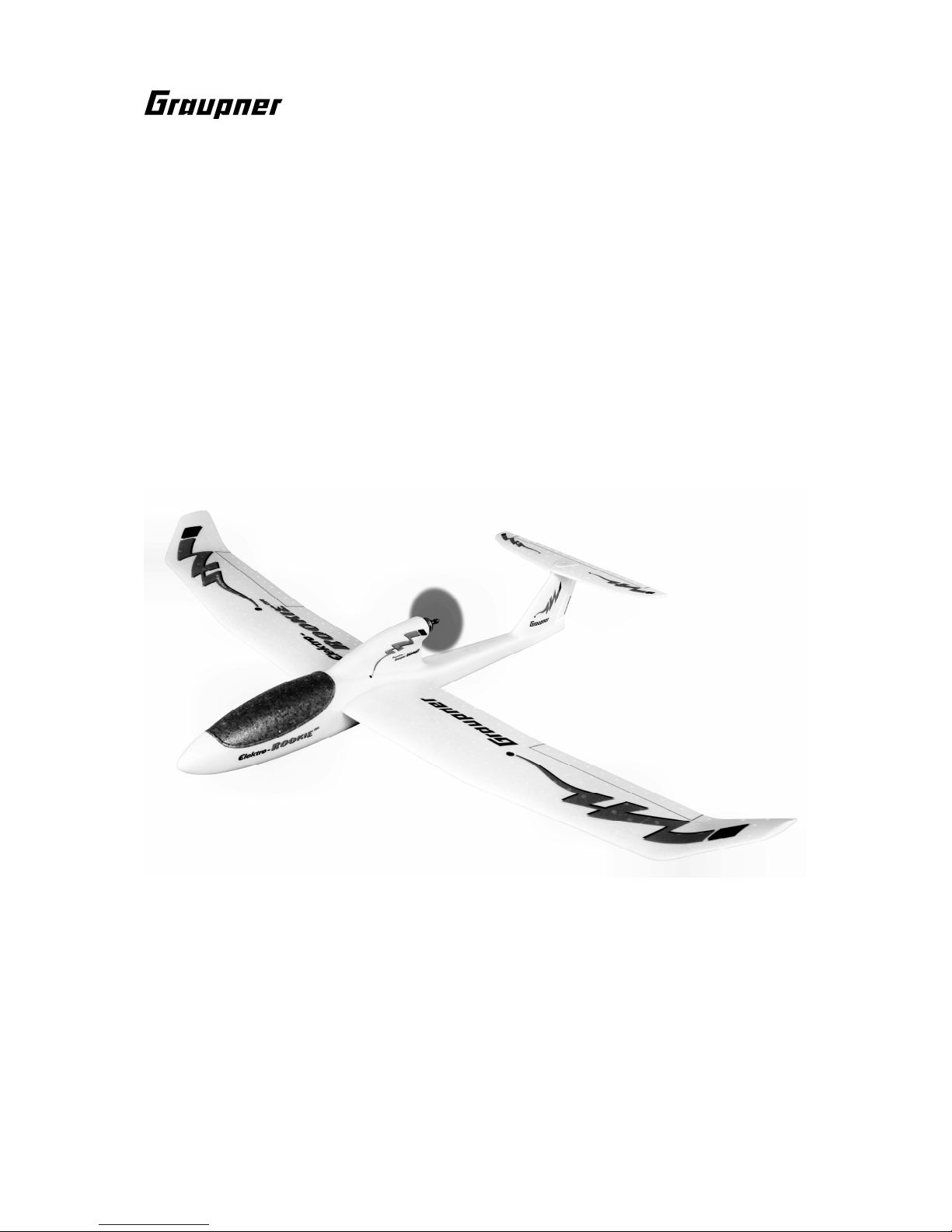
ELEKTRO-ROOKIE QR
ARTF
RC electric-powered model glider for three LiPo cells of 2500 mAh
This model requires a four-function HoTT radio control system
Page 2
GRAUPNER GmbH & Co. KG D-73230 KIRCHHEIM/TECK GERMANY
Modifications reserved. No liability for printing errors. Id.-Nr. 0062439 5/2011
- 2 -
Please be sure to read through the Safety Notes in the Appendix to these operating instructions. If you ever dispose of the model, it is important to pass on the complete building
instructions to the new owner.
Introduction
The ELEKTRO-ROOKIE QR is an RC model aircraft designed expressly for the newcomer to model flying, and offers a superb performance in the air. For safety reasons
the model’s all-up weight should not exceed 850 g.
RC system accessories (not included)
GRAUPNER MX-12 HoTT 2.4 COMPUTER SYSTEM Order No. 33112
Assembling the model
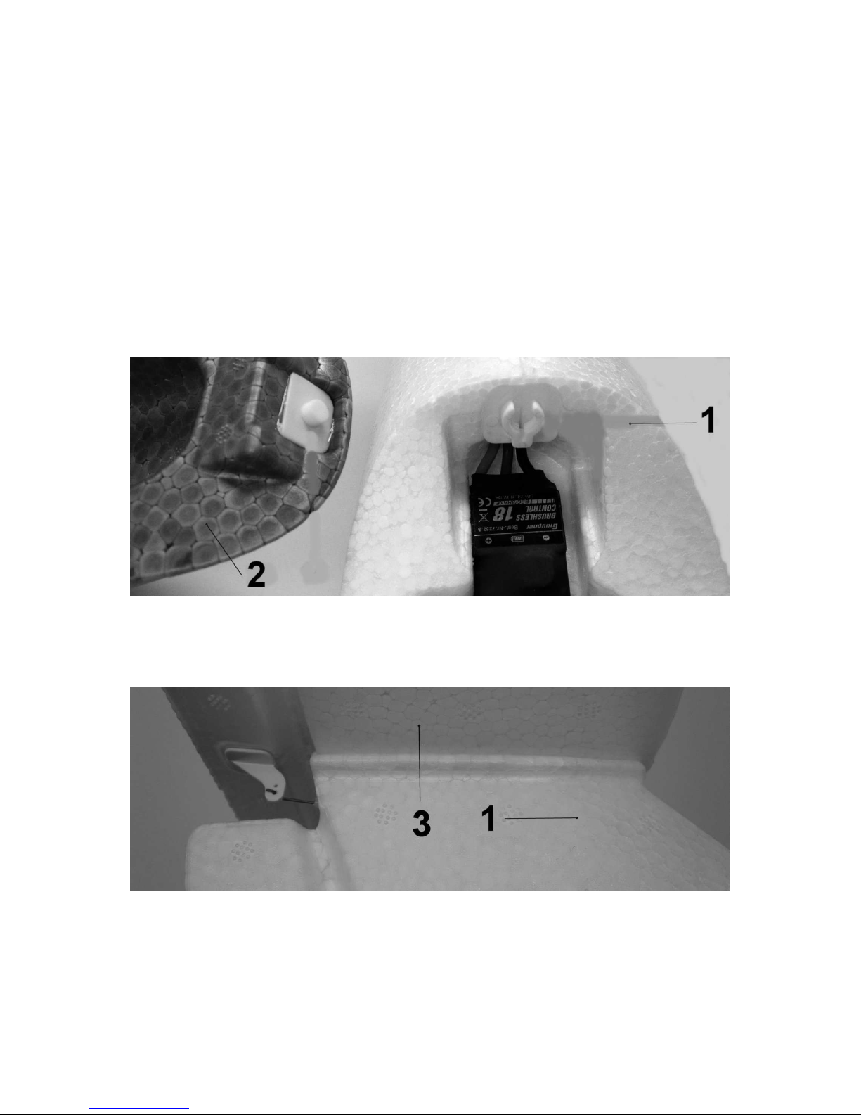
To remove the canopy (2) grasp it by both sides at the rear, and pull it up and off.
The photo shows the canopy (2), removed from the fuselage (1). if the retainer clip
grips too strongly for comfort, bend the two claws outwards, working gently and
evenly.
First connect the elevator pushrod to the outer hole in the elevator horn, then place
the tailplane (3) on the fin and fit the countersunk screw (4) to hold it in position. You
will need a suitable cross-point screwdriver for this; the tool is not included in the
pack.
Page 3
GRAUPNER GmbH & Co. KG D-73230 KIRCHHEIM/TECK GERMANY
Modifications reserved. No liability for printing errors. Id.-Nr. 0062439 5/2011
- 3 -
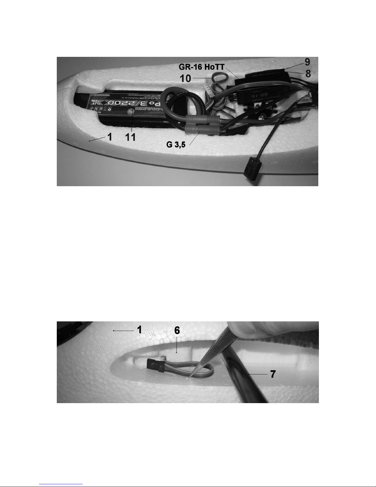
Installing the receiving system
The illustration shows the HoTT receiver (not included) installed above the rudder
servo using the Velcro tape (8) and (9). Route the receiver aerials through the fuselage opening above the speed controller. We recommend the following receiver
channel assignment: connect the speed controller to receiver socket I, the left aileron
servo to socket II, the elevator servo to socket III, the rudder servo to socket IV, the
right-hand aileron servo to socket V. Coil up the servo leads next to the receiver, so
that they cannot obstruct the servo output arms when they move. Connect the 100
mm servo extension leads (10) to sockets II and V.
The receiving system is switched on by plugging in the LiPo battery (11), i.e. by
connecting the G3.5 plugs and sockets as shown above. Bind the receiver to the
transmitter using the procedure outlined in the manual supplied with your RC system.
Check the direction of motor rotation: if the propeller spins clockwise when viewed
from the tail, disconnect the push-button (bottom of picture) from the speed controller.
Installing the wing
Slip the servo leads through the appropriate channel in the fuselage (1) as shown in
the picture; this is easier if you use a pair of tweezers or small pliers.
Page 4

GRAUPNER GmbH & Co. KG D-73230 KIRCHHEIM/TECK GERMANY
Modifications reserved. No liability for printing errors. Id.-Nr. 0062439 5/2011
- 4 -
Checking the control surfaces
The stick mode at the transmitter should be set as shown in the photograph: throttle
(motor speed) and direction (aileron) on the right-hand stick. Stick back (towards you)
equates to motor off; stick forward means full power. Elevator control should be on
the left-hand stick: pulling the stick back deflects the elevator up; pushing it away
from you produces down-elevator.
The rudder is operated by moving the left-hand stick left and right. If any function
works the wrong way round, use your transmitter’s servo reverse menu to correct that
channel.
Please read through the operating instructions for the BRUSHLESS CONTROL
18 speed controller; these are supplied separately.
Fitting the propeller
If you have to replace the propeller, install it as shown in the photo. Tighten the
spinner using a 1.5 mm Ø steel rod.
Caution: fit the propeller with the lettering facing forward, i.e. towards the
model’s nose. If you fit it the other way round, motor power will be greatly
reduced.
Page 5

GRAUPNER GmbH & Co. KG D-73230 KIRCHHEIM/TECK GERMANY
Modifications reserved. No liability for printing errors. Id.-Nr. 0062439 5/2011
- 5 -
Balancing
Assemble the model completely, including all the RC and power system components.
The Centre of Gravity range is 70 mm to 80 mm aft of the wing root leading edge
(see markings on the underside of the wing). Support the model at the stated CG
position with two fingers under the wing roots, and allow it to hang freely: when
balanced correctly, the fuselage will hang level.
Flying
Give the LiPo flight battery and transmitter battery a full charge, and assemble the
model completely. Check that the control surfaces are exactly at centre before flying.
For the initial test-flight wait for a day with little or no breeze. The ideal flying site is a
grassy field with a gentle slope facing into wind.
Switch the motor on and give the aeroplane a hand-launch exactly into any
breeze; trotting forward for a few steps gains the necessary momentum. The
model’s nose should be angled up slightly (around 15°) for a launch under
power.
Initially use the rudder and elevator controls gently, just to correct any deviations from
a straight flight path. Fine-tuning can be carried out by adjusting the trim sliders
situated below and adjacent to the transmitter sticks. Always land the model directly
into wind, with the motor switched off. Just before touch-down, apply slight upelevator to flare out and slow the machine down further.
All of us at GRAUPNER Modellbau wish you many fine flights with your new
ELEKTRO-ROOKIE QR
Specification
Wingspan approx. 1400 mm
Overall length approx. 960 mm
Wing airfoil HQ 3.0/12
Tailplane airfoil NACA 009
Wing area approx. 23.4 dm²
Tailplane area approx. 3.9 dm²
Total surface area approx. 27.3 dm²
Total surface area loading approx. 30.0 g/dm²
All-up weight approx. 820 g
Page 6

GRAUPNER GmbH & Co. KG D-73230 KIRCHHEIM/TECK GERMANY
Modifications reserved. No liability for printing errors. Id.-Nr. 0062439 5/2011
- 6 -
Replacement parts (not included)
Canopy Order No. 4218.1
Fuselage shells Order No. 4239.2
Wing panels Order No. 4239.3
Tailplane Order No. 4218.4
ABS small parts Order No. 4218.5
Decal sheet Order No. 4239.14
CFRP wing spar Order No. 4218.20
Propeller Order No. 2945.16.8
Pack contents - ELEKTRO-ROOKIE QR ARTF
No. Description No. off Material Dimensions, mm
1 Ready-made fuselage 1
SOLIDPOR®
Ready made
2 Canopy 1
SOLIDPOR®
Ready made
3 Tailplane 1
SOLIDPOR®
Ready made
4 Countersunk screw 1 Nylon M4 x 25
5 L.H. wing panel 1
SOLIDPOR®
Ready made
6 R.H. wing panel 1
SOLIDPOR®
Ready made
7 CFRP wing spar 1 CFRP 10 / 8 Ø x 600
8 Velcro tape, coarse 1 Plastic 33 x 25 x 3
9 Velcro tape, fine 1 Plastic 33 x 25 x 3
10 Servo extension lead 2 Metal / plastic Ready made, 100
11 LiPo battery with safety notes 1 LiPo 11.1 V / 2.5 Ah
12 LiPo charger and instructions 1 Metal / plastic Ready made
13 Speed controller instructions 1 Printed paper DIN A4
14 Operating instructions for the
ROOKIE QR ARTF
1 Printed paper DIN A4
15 DMFV insurance offer 1 Printed card DIN A5
Poly-bag with spare servo arms 4
Environmental Protection Notes
The presence of this symbol on a product, in the user instructions or the packaging, means
that you must not dispose of that item in the ordinary domestic waste when the product
comes to the end of its useful life. The correct method of disposal is to take it to your local
collection point for recycling electrical and electronic equipment.
Individual markings indicate which materials can be recycled and re-used. You can make
an important contribution to the protection of our shared environment by re-using the product,
recycling the basic materials or re-processing redundant equipment in other ways.
Dry cells and rechargeable batteries must be removed from the device and taken separately to a
suitable battery disposal centre.
If you don’t know the location of your nearest disposal centre, please enquire at your local council
office.
Safety Notes
Before you fly the model for the first time it is essential (and a legal requirement) to take out an insurance
policy designed to cover modelling risks.
Be sure to read right through the instructions covering assembly and operation of your model before you
attempt to operate it for the first time. You alone are responsible for the safe operation of your radio-
Page 7

GRAUPNER GmbH & Co. KG D-73230 KIRCHHEIM/TECK GERMANY
Modifications reserved. No liability for printing errors. Id.-Nr. 0062439 5/2011
- 7 -
controlled model aeroplane. Young people should only be permitted to build and fly this model under the
instruction and supervision of an adult who is aware of the hazards involved in this activity.
In legal terms our models are classed as aircraft, and as such are subject to statutory regulations and
restrictions which must be observed. Our brochure “Modellflugrecht, Paragrafen und mehr” (Model
Aviation Law, Legal Requirements and more) is available under Order No. 8034.02, and contains a
summary of all these rules; your local model shop should have a copy which you can read.
It is important to use only those parts included in the kit, together with other genuine Graupner
accessories and replacement parts as recommended expressly by us. Even if you change a single
component, you can no longer be sure that the whole system will work reliably, and such changes also
invalidate your guarantee.
Avoid short circuits and reverse polarity at all times.
The high energy density of rechargeable batteries involves a constant risk of fire and even explosion.
The operator of the model must be in full possession of his or her bodily and mental faculties. As with car
driving, flying a model aircraft under the influence of alcohol or drugs is highly dangerous and not
permissible under any circumstances.
Make sure that all passers-by and onlookers are aware of the hazards involved in the operation of your
model. Remind spectators to keep a safe distance from the model.
Always maintain a safe distance between your model and other people or objects. Never fly low over
people or directly towards them.
Radio-controlled models should only be flown in “normal” weather conditions, i.e. a temperature range of
-5° to +35°C. More extreme temperatures can lead to changes in battery capacity, material characteristics,
the strength of glued joints and other unwanted effects.
All model flyers should behave in a way which minimises the danger to people and property. Never act in
any manner which will disturb other pilots, or have an adverse effect on safe, orderly flying at the site.
Don’t operate your model aeroplane in the vicinity of overhead power cables, industrial sites, residential
areas, public roads, school playgrounds or sports fields etc.
Pre-flight checks
Check that the radio control system works correctly and at full range before every flight: switch on the
transmitter and the receiving system, fit the transmitter aerial and extend it to its full length; walk away
from the model, and check that all the control surfaces work smoothly and immediately at an appropriate
distance; check also that they deflect in the correct “sense” in relation to the stick movements. Repeat
the check with the motor running, while a friend holds the model securely for you.
If you are a relative beginner to this type of model flying, we recommend that you enlist an experienced
model pilot to help you check and test-fly the model.
Please don’t ignore our warnings. They refer to hazardous materials and processes which, if ignored, can
result in fatal injury or serious damage to property.
Propellers powered by a motor constitute a permanent hazard and represent a real risk of injury. Don’t
touch them with any part of your body. For example, a propeller spinning at high speed can easily cut
your finger badly.
Keep well clear of the rotational plane of the propeller. You never know when some part may come loose
and fly off at high speed, hitting you or anybody else in the vicinity. In unfavourable circumstances this
could result in serious injury. Ensure that the revolving propeller never comes into contact with any
object.
Make sure that it is impossible for any object to stall or block the propeller.
Every time you intend to operate your model, check carefully that it and everything attached to it (e.g.
propeller, RC components etc.) is in good condition and undamaged. If you find a fault, do not fly the
model until you have corrected it.
Never leave your radio control system unguarded, as other people might pick it up and try to use it.
Do not switch the electric motor on unless you have checked that there is nothing in the rotational plane
of the propeller. Never attempt to stop the propeller when it is spinning. Electric motors with propellers
fitted must only be run when firmly mounted.
Page 8

GRAUPNER GmbH & Co. KG D-73230 KIRCHHEIM/TECK GERMANY
Modifications reserved. No liability for printing errors. Id.-Nr. 0062439 5/2011
- 8 -
If you are to fly your model safely and avoid problems, it is essential that you are aware of its position
and attitude throughout each flight - so don’t let it fly too far away. If you detect a control problem or
interference during a flight, immediately land the model to prevent a potential accident. Model aeroplanes
must always give way to full-size aircraft. Take-off and landing strips should be kept free of people and
other obstacles.
Your RC system can only work reliably if the batteries are kept fully charged.
Remove the flight battery from the model after each flying session, and store it at a temperature of around
+5°C to +25°C, well out of the reach of children.
Never use hot, faulty or damaged batteries. It is important to observe the instructions supplied by the
battery manufacturer.
Before every flight ensure that all functions are working correctly, and carry out a range check.
Always ensure that the throttle stick (or other throttle control) is at the motor OFF position before
switching the transmitter on. To avoid the electric motor bursting into life unexpectedly, always switch
the transmitter on first, followed by the receiving system. When switching off, reverse the order: receiving
system first, then the transmitter.
Check that the control surfaces work in the correct “sense”, i.e. that they deflect in the direction which
corresponds to the movement of the stick.
Please don’t misunderstand the purpose of these notes. We only want to make you aware of the many
dangers and hazards which can arise if you lack knowledge and experience, or work carelessly or
irresponsibly. Provided that you take reasonable care, model flying is a highly creative, instructive,
enjoyable and relaxing pastime.
Manufacturer’s declaration:
If material defects or manufacturing faults should arise in a product distributed by us in the Federal
Republic of Germany and purchased by a consumer (§ 13 BGB), we, Graupner GmbH & Co. KG, D-73230
Kirchheim/Teck, Germany, acknowledge the obligation to correct those defects within the limitations
described below.
The consumer is not entitled to exploit this manufacturer’s declaration if the failure in the usability of the
product is due to natural wear, use under competition conditions, incompetent or improper use (including
incorrect installation) or external influences.
This manufacturer’s declaration does not affect the consumer’s legal or contractual rights regarding
defects arising from the purchase contract between the consumer and the vendor (dealer).
Extent of the guarantee
If a claim is made under guarantee, we undertake at our discretion to repair or replace the defective
goods. We will not consider supplementary claims, especially for reimbursement of costs relating to the
defect (e.g. installation / removal costs) and compensation for consequent damages unless they are
allowed by statute. This does not affect claims based on legal regulations, especially according to
product liability law.
Guarantee requirements
The purchaser is required to make the guarantee claim in writing, and must enclose original proof of
purchase (e.g. invoice, receipt, delivery note) and this guarantee card. The purchaser must send the
defective goods to us at his own cost, using the address stated above.
The purchaser should state the material defect or manufacturing fault, or the symptoms of the fault, in as
accurate a manner as possible, so that we can check if our guarantee obligation is applicable.
The goods are transported from the consumer to us and from us to the consumer at the consumer’s risk.
Duration of validity
This declaration only applies to claims made to us during the claim period as stated in this declaration.
The claim period is 24 months from the date of purchase of the product by the consumer from a dealer in
the Federal Republic of Germany (purchase date). If a defect arises after the end of the claim period, or if
the evidence or documents required according to this declaration in order to make the claim valid are not
presented until after this period, then the consumer forfeits any rights or claims from this declaration.
Limitation by lapse of time
If we do not acknowledge the validity of a claim based on this declaration within the claim period, all
claims based on this declaration are barred by the statute of limitations after six months from the time of
implementation; however, this cannot occur before the end of the claim period.
Applicable law
This declaration, and the claims, rights and obligations arising from it, are based exclusively on the
pertinent German Law, excluding the norms of international private law, and excluding UN retail law.
 Loading...