

Page 1
GRAUPNER/SJ GmbH D-73230 KIRCHHEIM/TECK GERMANY
Modifications reserved. No liability for printing errors. 03/2013
1
Order No. 9502
Assembly Instructions
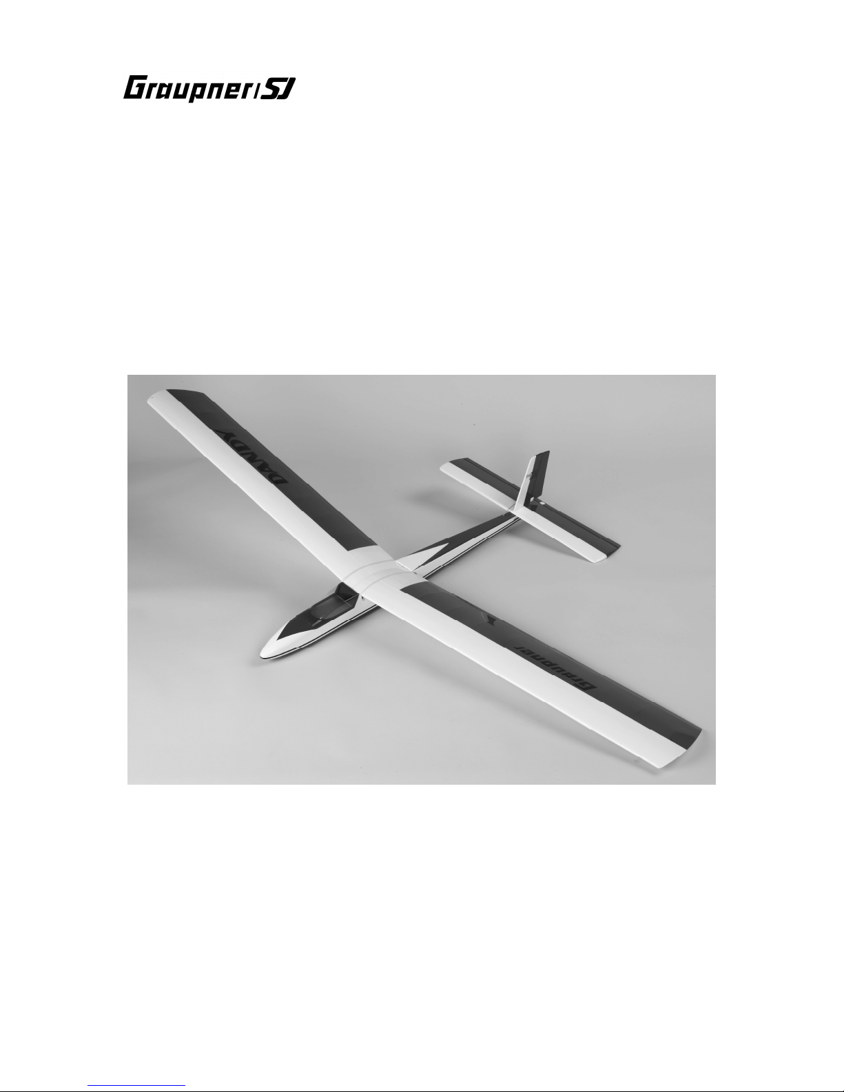
DANDY
ARTF RC model aircraft
Wingspan approx. 1600 mm
This model requires a two-function HoTT COMPUTER SYSTEM
Page 2

GRAUPNER/SJ GmbH D-73230 KIRCHHEIM/TECK GERMANY
Modifications reserved. No liability for printing errors. 03/2013
2
Please be sure to observe the safety notes included in the Appendix to these assembly instructions. If you ever dispose of the model, the complete operating instructions and safety notes
must also be passed on to the new owner.
Introduction
The DANDY is a classic Graupner/SJ model aircraft which offers an outstanding performance in the air. The DANDY was first introduced way back in 1968, and its
design remains timelessly elegant. The model can be launched by hand-tow or
bungee, but can also be flown as a powered glider with a motor pylon.
It is fundamentally essential to read through these operating instructions before you
fly the model for the first time, and to familiarise yourself with the instructions supplied with your HoTT COMPUTER SYSTEM.
Pack contents
1. Fuselage with control surface linkages, canopy, decals applied
2. Pair of wing panels, decals applied
3. Tailplane and fin, decals applied
4. Steel rod wing joiner, 4 Ø x 150 mm
5. Small parts pack
6. Assembly instructions in German, English and French
Please take the time to become familiar with the components before you start assembling the model. If anything is missing, or you are not satisfied with any component,
please contact your retail supplier before you start building the aeroplane.
Essential additional items (not included)
Graupner/SJ MX-10 HoTT computer system Order No. 33110
DES 657 BB servo (2 required) Order No. 7935
ULTRAMAT 8 battery charger Order No. 6411
BEC charge lead Order No. 3037
BRUSHLESS CONTROL 18 BEC* Order No. 7232
LiPo battery, 2/2500 7.4 V BEC 20C* Order No. 7633.2 BEC
*
These two items are recommended as the power supply for the receiving system. If you intend to fit the model with the
motor pylon at a later date, no additional RC system components are required.
Essential adhesives (not included)
Cyano-acrylate (“cyano”) Order No. 5821
Cyano-acrylate activator Order No. 953.150
UHU-ALLESKLEBER Kraft (general-purpose adhesive) Order No. 1096
Essential tools (not included)
Set-square, scissors, balsa knife, side-cutters, set of twist drills, flat-nose pliers, 2.5
mm A/F allen key, screwdriver.
Assembling the model
The model requires only a few hours’ work to complete, but these instructions must
still be observed very carefully to ensure that the first flight in particular is successful.
Fuselage, fin and tailplane
Insert the fin in the slot in the tailplane, use a set-square to check that it is vertical,
and apply masking tape as shown to hold it in position. Apply cyano along the
corners on both sides; the thin adhesive “wicks” into the joint.
Page 3

GRAUPNER/SJ GmbH D-73230 KIRCHHEIM/TECK GERMANY
Modifications reserved. No liability for printing errors. 03/2013
3
The next step is to pull off the rudder and elevator, and glue the hinges in place using
UHU-ALLESKLEBER Kraft. The adhesive should be applied sparingly to avoid an
accumulation of glue at the pivot line. The gap between the fixed and moving panels
should be about 0.5 mm.
Prepare the rudder and elevator servos by pressing the rubber grommets and metal
spacers into the mounting lugs; these parts are supplied with the servos.
The pictures show how the grommets and spacers are fitted to the servos.
Remove the servo output levers, cut them down to the shapes shown in the pictures,
and fit them on the servos again; don’t forget the output screws. Check from the
transmitter that the servos are at centre (neutral) when the output arms are fitted on
the shafts. The servos can now be fitted in the fuselage. Each is secured using four
self-tapping screws, which are also included in the servo accessory packs.
Page 4

GRAUPNER/SJ GmbH D-73230 KIRCHHEIM/TECK GERMANY
Modifications reserved. No liability for printing errors. 03/2013
4
The tail group can now be fixed to the fuselage; the assembly is secured using two
socket-head screws and washers. Fit the screws and tighten them using a 2.5 mm
A/F allen key. Don’t over-tighten them: they should be just tight enough to prevent
the tail assembly shifting on the fuselage.
The next step is to attach the horns to the rudder and elevator, as shown in the
pictures. First connect the clevises to the horns.
You may need to bend the pushrods slightly where they exit the fuselage at the tail
end to ensure that they move smoothly. Position the horns on the control surfaces
with the linkage holes directly over the hinge pivot line, then mark the hole positions,
remove the horns and drill 2 mm Ø holes at the marked points. Fix the horns to the
rudder and elevator using a spreader plate and two pan-head screws each.
Page 5

GRAUPNER/SJ GmbH D-73230 KIRCHHEIM/TECK GERMANY
Modifications reserved. No liability for printing errors. 03/2013
5
Snip off the projecting screw shanks using side-cutters. Protect your eyes!
Tape the control surfaces at neutral, and mark the correct length of the pushrods at
the servo output arms. Bend the rods at right-angles at the marked point and snip off
the excess material, leaving about 1 mm projecting when the pushrod keepers are in
place.
The wing is retained on the fuselage using rubber bands which are stretched
between two aluminium dowels. Fit the dowels through the holes in the fuselage and
centre them (equal projection on both sides). Secure them with a few drops of
cyano.
Drill a central 1 mm Ø hole in the underside of the fuselage for the towhook. Screw
the hook into the hole, and secure it with a drop of cyano.
Page 6

GRAUPNER/SJ GmbH D-73230 KIRCHHEIM/TECK GERMANY
Modifications reserved. No liability for printing errors. 03/2013
6
The position of the towhook is shown in the pictures. The towhook is not required if
you only intend to fly the model from a slope or with the motor pylon attached.
The canopy has to be trimmed to match the outside shape of the canopy frame
before the parts are glued together: apply a strip of masking tape on each side of the
fuselage, flush with the bottom edge of the cabin.
Place the canopy on the canopy frame, and rub the tape onto the moulding to mark
the underside of the fuselage recess. Remove the tape from the fuselage to release
the canopy. Cut off the excess canopy material along the top edge of the tape before
gluing the moulding in place using UHU ALLESKLEBER Kraft. Tape the canopy in
place while the glue is hardening.
Installing the receiving system
Connect the servo leads to the receiver in the following sequence: socket 1 speed
controller, socket 2 rudder servo, socket 3 elevator servo. Refer to the diagram
printed on the receiver to ensure that all the leads are plugged in the right way round:
the brown wire is always at the top of the receiver. The receiver should be supported
loosely in the fuselage in soft foam. Please note that the receiving system is switched
on when you connect the BEC plug and socket between the speed controller and the
LiPo battery.
Please note that for safety reasons the BEC plug and socket must always be
disconnected after running the motor or flying the model; this also helps to
protect the LiPo battery. If the BEC plug and socket are left connected, a small
Page 7

GRAUPNER/SJ GmbH D-73230 KIRCHHEIM/TECK GERMANY
Modifications reserved. No liability for printing errors. 03/2013
7
current flows even when the model is not in use, and in course of time this results in
irreparable damage to the LiPo battery due to deep-discharging.
The DANDY with motor pylon
A useful option if you wish to be able to fly the DANDY from a flat field without using
a towline or bungee system is to install the motor pylon, Order No. 2917 (motor
pylon set not included in the pack).
Slip the prepared motor pylon onto the wing joiner rod until it rests against the wing
root, as shown above. Now fit the other wing panel on the joiner rod until it also
makes contact with the pylon.
Cut a hole about 10 mm in diameter in the former aft of the canopy. The BEC lead
attached to the speed controller passes through this hole to the LiPo flight battery.
Control surface travels
The rudder and elevator travels should be set as follows, in each case measured at
the trailing edge of the control surface and at the inboard end: elevator about 5 mm
up and down, rudder about 25 mm to both sides of centre. The two-position switch for
the Dual Rate function at top right of the MX-10 transmitter can be used to reduce all
the travels by 30%: move the toggle switch back to reduce travels. For the first few
flights we recommend activating the Dual Rate function, i.e. you should fly the model
with reduced travels.
Page 8

GRAUPNER/SJ GmbH D-73230 KIRCHHEIM/TECK GERMANY
Modifications reserved. No liability for printing errors. 03/2013
8
The Centre of Gravity range
The safe C.G. position for the DANDY is located at 103 mm from the wing root
leading edge. Check the CG by supporting the model on two fingertips at the stated
point under both wing roots: it should then balance level. The LiPo battery can be repositioned further forward if necessary to obtain the correct CG. Alternatively add a
little nose ballast (not included).
Flying
Assemble the model completely, charge all the batteries, and check that the control
surfaces are properly centred before undertaking the first flight. Wait for a day with
little or no breeze. A good flying site is a flat grassy field, ideally with a gentle slope
facing into wind.
Note: for the initial test-glide push the model forward directly into any wind; the
fuselage nose should be angled down slightly (by about 10°). If necessary use
very slight rudder and elevator commands to keep the model gliding straight and flat.
Fine-tuning is carried out using the trim sliders below and adjacent to the transmitter
sticks. Always land the model directly into wind.
All of us at Graupner/SJ Modellbau hope you enjoy many fine flights with your new
DANDY
The picture shows the DANDY fitted with the motor pylon No. 2917 during a fast low
pass.
Page 9

GRAUPNER/SJ GmbH D-73230 KIRCHHEIM/TECK GERMANY
Modifications reserved. No liability for printing errors. 03/2013
9
Specification - DANDY
Wingspan approx. 1600 mm
Overall length approx. 975 mm
Wing area approx. 27.8 dm²
Tailplane area approx. 7.0 dm²
Total surface area approx. 34.8 dm²
Total surface area loading approx. 27,2 g/dm²
All-up weight approx. 950 g
Longitudinal dihedral approx. 2°
Replacement parts (not included)
Canopy Order No. 9502.1
Fuselage Order No. 9502.2
Wing panels Order No. 9502.3
Tailplane Order No. 9502.4
Decal sheet Order No. 9502.14
Safety Notes
Caution: cyano-acrylate adhesive must never be allowed to contact any part of your body, and your eyes
in particular. For this reason we recommend the use of gloves and goggles when handling these
materials. The workshop should be effectively ventilated. Store the adhesive out of the reach of children.
It is a legal requirement to obtain third-party insurance before you operate any model aircraft.
Before attempting to operate the model for the first time it is essential to read right through the operating
instructions attentively. You alone are responsible for the safe operation of your RC model aircraft. Young
persons must be supervised by a responsible adult who is aware of the possible hazards involved in the
operation of model aeroplanes.
In legal terms our models are classed as aircraft, and as such are subject to legal regulations and
restrictions which must be observed at all times.
Avoid short-circuits at all times. The high energy density of the batteries used in modelling involves a
constant risk of explosion and fire.
A radio-controlled model aircraft can only work properly and fulfil your expectations if it is built very
carefully, and in accordance with the building instructions. Nobody would climb into a full-size sailplane
and try to fly it without first completing a course of training. Model flying is just such a skill, and has to be
learned in exactly the same way.
However, as manufacturers we have no means of influencing the way you build and operate your RC
model aircraft, and for this reason we can do no more than point out the hazards expressly. We accept no
further liability.
If you need help, please enlist the aid of an experienced modeller, join a model club or enrol at a model
flying training school. Model shops and the specialist model press are also good sources of information.
The best course is always to join a club and fly at the approved model flying site.
Adhesives contain substances which can be harmful to health under certain circumstances. It is therefore
important to read and observe the notes and warnings supplied by the glue manufacturer.
The operator must be in possession of his full bodily and mental capabilities. As with car driving, it is not
permissible to fly a model aircraft under the effect of alcohol or drugs.
Make sure that all passers-by and onlookers are aware of the hazards involved in the operation of your
model. Remind spectators to keep a safe distance from the model.
Always maintain a safe distance between your model and other people or objects. Never fly low over
people or directly towards them.
Radio-controlled models should only be flown in “normal” weather conditions, i.e. a temperature range of
-5° to +35°C. More extreme temperatures can lead to changes in battery capacity, material characteristics,
the strength of glued joints and other unwanted effects.
All model flyers should behave in a way which minimises the danger to people and property. Never act in
any manner which will disturb other pilots, or have an adverse effect on safe, orderly flying at the site.
Page 10

GRAUPNER/SJ GmbH D-73230 KIRCHHEIM/TECK GERMANY
Modifications reserved. No liability for printing errors. 03/2013
10
Don’t operate your model aeroplane in the vicinity of overhead power cables, industrial sites, residential
areas, public roads, school playgrounds or sports fields etc.
Pre-flight checks
Check that the radio control system works correctly and at full range before every flight: switch on the
transmitter and receiving system, and ensure that all the control surfaces work smoothly, and deflect in
the correct “sense” in relation to the stick movements.
If you are a beginner to this type of model flying, we recommend that you enlist an experienced model
pilot to help you check and test-fly the model.
Please don’t ignore our warnings. They refer to hazardous materials and processes which, if ignored, can
result in fatal injury or serious damage to property.
If you are to fly your model safely and avoid problems, it is essential that you are aware of its position
and attitude throughout each flight - so don’t let it fly too far away. If you detect a control problem or
interference during a flight, immediately land the model to prevent a potential accident. Model aeroplanes
must always give way to full-size aircraft. Take-off and landing strips should be kept free of people and
other obstacles.
Your RC system can only work reliably if the batteries are kept fully charged.
Never use hot, faulty or damaged batteries. It is important to observe the instructions supplied by the
battery manufacturer.
Manufacturer’s declaration:
If material defects or manufacturing faults should arise in a product distributed by us in the Federal
Republic of Germany and purchased by a consumer (§ 13 BGB), we, Graupner/SJ GmbH, D-73230
Kirchheim/Teck, Germany, acknowledge the obligation to correct those defects within the limitations
described below.
The consumer is not entitled to exploit this manufacturer’s declaration if the failure in the usability of the
product is due to natural wear, use under competition conditions, incompetent or improper use (including
incorrect installation) or external influences.
This manufacturer’s declaration does not affect the consumer’s legal or contractual rights regarding
defects arising from the purchase contract between the consumer and the vendor (dealer).
Extent of the guarantee
If a claim is made under guarantee, we undertake at our discretion to repair or replace the defective
goods. We will not consider supplementary claims, especially for reimbursement of costs relating to the
defect (e.g. installation / removal costs) and compensation for consequent damages unless they are
allowed by statute. This does not affect claims based on legal regulations, especially according to
product liability law.
Guarantee requirements
The purchaser is required to make the guarantee claim in writing, and must enclose original proof of
purchase (e.g. invoice, receipt, delivery note) and this guarantee card. The purchaser must send the
defective goods to us at his own cost, using the address stated above.
The purchaser should state the material defect or manufacturing fault, or the symptoms of the fault, in as
accurate a manner as possible, so that we can check if our guarantee obligation is applicable.
The goods are transported from the consumer to us and from us to the consumer at the risk of the
consumer.
Duration of validity
This declaration only applies to claims made to us during the claim period as stated in this declaration.
The claim period is 24 months from the date of purchase of the product by the consumer from a dealer in
the Federal Republic of Germany (purchase date). If a defect arises after the end of the claim period, or if
the evidence or documents required according to this declaration in order to make the claim valid are not
presented until after this period, then the consumer forfeits any rights or claims from this declaration.
Limitation by lapse of time
If we do not acknowledge the validity of a claim based on this declaration within the claim period, all
claims based on this declaration are barred by the statute of limitations after six months from the time of
implementation; however, this cannot occur before the end of the claim period.
Applicable law
This declaration, and the claims, rights and obligations arising from it, are based exclusively on the
pertinent German Law, excluding the norms of international private law, and excluding UN retail law.
 Loading...