

Page 1
zu Best.-Nr. 4546
Anleitung
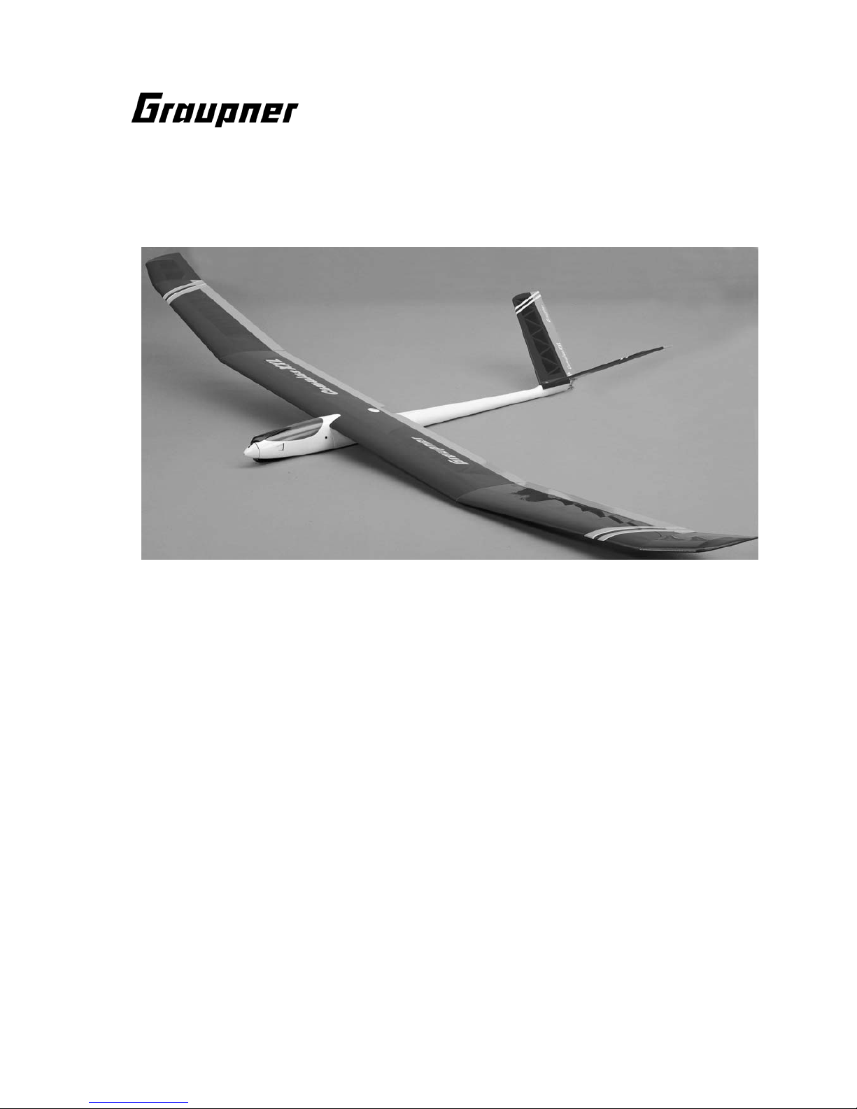
CUMULUS XXL
Für Elektroantrieb mit 8 Zellen
Es wird eine Fernsteuerung mit 5 Funktionen benötigt
GRAUPNER GmbH & Co. KG D-73230 KIRCHHEIM/TECK GERMANY
Änderungen vorbehalten! Keine Haftung für Druckfehler! Ident-Nr. 46413 04/2003
Made in Tschechien
Page 2

Vorwort
Durch den hohen Vorfertigungsgrad, kommt auch der Anfänger schnell zum Fliegen.
Die Geschwindigkeit im Kraftflug als auch im Segelflug sind optimal aufeinander
abgestimmt, d. h., der Geschwindigkeitsunterschied ist kaum merkbar, was für einen
Anfänger eine wesentliche Erleichterung darstellt.
Durch die niedrige Flächenbelastung und Fluggeschwindigkeit sollte CUMULUS
XXL bei stärkerem Wind erst nach etlichen Flugstunden bei ruhigem Wetter
geflogen werden.
Für Kunstflug ist CUMULUS XXL nicht ausgelegt, man kann aber mit dosierten
Ausschlägen einen Looping oder eine hochgezogene Fahrtkurve fliegen.
CUMULUS XXL spricht sehr gut auf Thermik an und lässt sich sehr gut kreisen.
Sollte CUMULUS XXL einmal zu hoch steigen, durch z. B. starke Thermik, ist ein
sicherer Abstieg mit der Butterfly-Stellung von Wölbklappe und Querrudern möglich.
Achtung: Diese Modell ist kein Spielzeug!
Sollten Sie mit solch motorisiertem Modell keine Erfahrung haben, wenden Sie sich
bitte an erfahrene Modellflieger, die Sie unterstützen können. Es könnte zu
Verletzungen kommen, wenn das Modell ohne Vorkenntnisse in Betrieb genommen
wird. Denken Sie an die Sicherheit und Ihre Gesundheit.
Wichtig! Bevor Sie mit dem Bau beginnen!
Auch wenn Sie schon viele RC-Modelle gebaut haben, lesen Sie diese Anleitung
genauestens durch und kontrollieren Sie die Teile dieses Bausatzes auf
Vollständigkeit. Es wurde viel Mühe darauf verwandt, den Aufwand möglichst
einfach zu halten, ohne die Sicherheit zu beeinträchtigen.
Hinweis zur Folienbespannung
Auf Grund von starken Wetteränderungen (Temperatur, Feuchtigkeit etc.) können in
der Bespannfolie kleine Falten auftreten. In seltenen Fällen auch ein Verzug der
Bauteile. Dies liegt in der Natur der Holzbauweise mit Folienbespannung. Es kann,
wie folgt, mit einem Heißluftgebläse (Fön), wie sie für den Modellbauer angeboten
werden, wieder korrigiert werden.
Falten: Mit Warmluft anblasen und mit weichem Tuch anreiben.
Verzogener Flügel: Flügel dem Verzug entgegen leicht verdreht aufspannen und mit
Warmluft die Bespannung wieder glätten.
Vorsicht! Nicht mehr Wärme zuführen, als unbedingt notwendig. Bei zu heißem
Bügeleisen schmilzt die Folie und es entstehen Löcher.
Das weitgehend vorgefertigte Modell benötigt nur noch wenig Bauzeit. Aber die
verbleibenden Arbeiten sind wichtig und müssen sorgfältig ausgeführt werden. Von
deren einwandfreier Ausführung hängt es ab, ob das Modell letztlich die
vorgesehene Festigkeit und Flugeigenschaften haben wird; deshalb langsam und
präzise arbeiten!
Page 3

Hinweis zur Benutzung von CUMULUS XXL
Vor dem Versuch der ersten Inbetriebnahme muss die gesamte Betriebs- und
Montageanleitung sorgfältig gelesen werden. Sie alleine sind verantwortlich
für den sicheren Betrieb Ihres RC-Flugmodells. Bei Jugendlichen unter 12
Jahren muss der Bau und Betrieb von einem Erwachsenen, der mit den
Gegebenheiten und möglichen Gefahren eines RC-Flugmodells vertraut ist,
verantwortlich überwacht werden.
Diese Bedienungsanleitung muss sorgfältig aufbewahrt und im Falle einer
Weitergabe dem nachfolgenden Benutzer unbedingt mit ausgehändigt werden.
Fragen, die die Sicherheit beim Betrieb des RC-Flugmodells betreffen, werden
Ihnen vom Fachhandel gerne beantwortet.
Fernsteuer-Flugmodelle sind sehr anspruchsvolle und gefährliche
Gegenstände und erfordern vom Betreiber einen hohen Sachverstand, Können
und Verantwortungsbewusstsein.
Rechtlich gesehen, ist ein Flugmodell ein Luftfahrzeug und unterliegt
entsprechenden Gesetzen, die unbedingt eingehalten werden müssen. Die
Broschüre "Luftrecht für Modellflieger", Best.-Nr. 8032, stellt eine
Zusammenfassung dieser Gesetze dar; sie kann auch beim Fachhandel
eingesehen werden. Ferner müssen postalische Auflagen, die die
Fernlenkanlage betreffen, beachtet werden. Entsprechende Hinweise finden
Sie in der Bedienungsanleitung Ihrer Fernsteueranlage.
Es dürfen nur die im Bausatz enthaltenen Teile, sowie die ausdrücklich von
uns empfohlenen Original-Graupner-Zubehör- und Ersatzteile verwendet
werden. Wird auch nur eine Komponente der Antriebseinheit geändert, ist ein
sicherer Betrieb nicht mehr gewährleistet und es erlischt jeglicher etwaiger
Garantieanspruch.
Verwenden Sie immer nur passende, verpolungssichere Steckverbindungen.
Alle stromführenden Leitungen, Steckverbindungen, sowie die
Antriebsbatterie, bei Selbstkonfektionierung, kurzschlusssicher isolieren.
Kombinieren Sie niemals unterschiedliche, z. B. Blech- und Goldkontakte, da
hier keine sichere Funktion gewährleistet ist.
Bei Verwendung von Schaltern bzw. Reglern mit Empfängerstromversorgung
nur Steckverbindungen mit Graupner-Gold-Kontakten verwenden.
Kurzschlüsse und Falschpolungen vermeiden.
Durch die hohe Energie der NC-Batterien besteht Explosions- und
Brandgefahr.
Ein RC-Flugmodell kann nur funktionsfähig sein und den Erwartungen
entsprechen, wenn es im Sinne der Bauanleitung sorgfältigst gebaut wurde.
Nur ein vorsichtiger und überlegter Umgang beim Betrieb schützt vor
Personen- und Sachschäden. Niemand würde sich in ein Flugzeug setzen und
- ohne vorausgegangene Schulung - versuchen, damit zu fliegen. Auch
Modellfliegen will gelernt sein.
Der Hersteller hat jedoch keine Möglichkeit, den Bau und den Betrieb eines
RC-Flugmodells zu beeinflussen. Deshalb wird hiermit auf die Gefahren
nachdrücklich hingewiesen und jede Haftung dafür abgelehnt.
Page 4

Bitte wenden Sie sich dazu an erfahrene Modellflieger, an Vereine oder
Modellflugschulen. Ferner sei auf den Fachhandel und die einschlägige
Fachpresse verwiesen. Am besten als Club-Mitglied auf zugelassenem
Modellflugplatz fliegen.
Sie alleine sind verantwortlich für den sicheren Betrieb Ihres RCSegelflugmodells.
Fragen, die die Sicherheit beim Betrieb des RC-Flugmodells betreffen, werden
Ihnen vom Fachhandel gerne beantwortet.
Klebstoffe und Lacke enthalten Lösungsmittel, die unter Umständen
gesundheitsschädlich sein können. Beachten Sie daher unbedingt auch die
entsprechenden Hinweise und Warnungen der Hersteller.
Der Betreiber muss im Besitz seiner vollen körperlichen und geistigen
Fähigkeiten sein. Wie beim Autofahren, ist der Betrieb des Flugmodells unter
Alkohol oder Drogeneinwirkung nicht erlaubt.
Informieren Sie alle Passanten und Zuschauer vor der Inbetriebnahme über
alle möglichen Gefahren, die von Ihrem Modell ausgehen und ermahnen diese,
sich in ausreichendem Schutzabstand, wenigstens 5 m hinter der
Luftschraubenebene, aufzuhalten.
Stets mit dem notwendigen Sicherheitsabstand zu Personen oder
Gegenständen fliegen; nie Personen in niedriger Höhe überfliegen oder auf sie
zufliegen!
Modellflug darf nur bei Außentemperaturen von - 5º C bis + 35º C betrieben
werden. Extremere Temperaturen können zu Veränderungen von z. B.
Akkukapazität, Werkstoffeigenschaften und mangelhafte Klebeverbindungen
führen.
Jeder Modellflieger hat sich so zu verhalten, dass die öffentliche Sicherheit
und Ordnung, insbesondere andere Personen und Sachen, sowie die Ordnung
des Modellflugbetriebs nicht gefährdet oder gestört wird.
Das Flugmodell niemals in der Nähe von Hochspannungsleitungen,
Industriegelände, in Wohngebieten, öffentlichen Straßen, Plätzen, Schulhöfen,
Parks und Spielplätzen usw. fliegen lassen.
Warnungen müssen unbedingt beachtet werden. Sie beziehen sich auf Dinge
und Vorgänge, die bei einer Nichtbeachtung zu schweren - in Extremfällen
tödlichen Verletzungen oder bleibenden Schäden führen können.
Luftschrauben und generell alle sich drehenden Teile, die durch einen Motor
angetrieben werden, stellen eine ständige Verletzungsgefahr dar. Sie dürfen
mit keinem Körperteil berührt werden! Eine schnell drehende Luftschraube
kann z. B. einen Finger abschlagen!
Sich niemals in oder vor der Drehebene von Luftschrauben aufhalten! Es
könnte sich doch einmal ein Teil davon lösen und mit hoher Geschwindigkeit
Page 5

und viel Energie wegfliegen und Sie oder Dritte treffen. Darauf achten, dass
kein sonstiger Gegenstand mit einer laufenden Luftschraube in Berührung
kommt!
Die Blockierung der Luftschraube, durch irgendwelche Teile, muss
ausgeschlossen sein.
Vorsicht bei losen Kleidungsstücken wie Schals, weiten Hemden usw.: sie
werden vom Propellerstrahl angesaugt und können in den Luftschraubenkreis
gelangen.
Überprüfen Sie vor jeder Inbetriebnahme das Modell und alle an ihm
gekoppelten Teile (z. B. Luftschrauben, Getriebe, RC-Teile usw.) auf festen Sitz
und mögliche Beschädigungen. Das Modell darf erst nach Beseitigung aller
Mängel in Betrieb genommen werden.
Auf gute Standfestigkeit achten, wenn Sie das Modell in der Hand halten.
Passendes Schuhwerk, z. B. Sportschuhe tragen.
Vergewissern Sie sich, dass die verwendete Frequenz frei ist. Erst dann
einschalten! Funkstörungen, verursacht durch Unbekannte, können stets
ohne Vorwarnung auftreten! Das Modell ist dann steuerlos und
unberechenbar! Fernlenkanlage nicht unbeaufsichtigt lassen, um ein
Betätigen durch Dritte zu verhindern.
Elektromotor nur einschalten, wenn nichts im Drehbereich der Luftschraube
ist. Nicht versuchen, die laufende Luftschraube anzuhalten. Elektromotor mit
Luftschraube nur im fest eingebauten Zustand laufen lassen.
Die Fluglage des Modells muss während des gesamten Fluges immer
eindeutig erkennbar sein, um immer ein sicheres Steuern und Ausweichen zu
gewährleisten. Machen sich während des Fluges
Funktionsbeeinträchtigungen/Störungen bemerkbar, muss aus
Sicherheitsgründen sofort die Landung eingeleitet werden. Sie haben anderen
Luftfahrzeugen stets auszuweichen. Start- und Landeflächen müssen frei von
Personen und sonstigen Hindernissen sein.
Immer auf vollgeladene Akkus achten, da sonst keine einwandfreie Funktion
der RC-Anlage gewährleistet ist.
Niemals heiß gewordene, defekte oder beschädigte Batterien verwenden. Es
sind stets die Gebrauchsvorschriften des Batterieherstellers zu beachten.
Vor jedem Flug eine Überprüfung der kompletten RC-Anlage, sowie des
Flugmodells auf volle Funktionstüchtigkeit und Reichweite durchführen.
Dabei ist zu beachten, dass bei der Inbetriebnahme die Motorsteuerfunktion
am Sender immer zuerst in AUS-Stellung gebracht wird. Danach Sender und
dann erst Empfangsanlage einschalten, um ein unkontrolliertes Anlaufen des
Elektromotors zu vermeiden. Gleichfalls gilt immer zuerst Empfangsanlage
ausschalten, danach erst den Sender.
Überprüfen Sie, dass die Ruder sich entsprechend der Steuerknüppelbetätigung bewegen.
Page 6

Beim Bewegen des Seitenruder-Steuerknüppels nach rechts, muss das rechte
Höhenruder nach unten und das linke Höhenruder nach oben ausschlagen.
Beim Bewegen des Höhen-/Tiefenruder-Knüppels nach hinten, zum Bauch,
müssen beide Ruder nach oben ausschlagen.
Beim Fliegen keine abrupten Steuerknüppelbewegungen durchführen.
Nach Gebrauch alle Batterien aus dem Modell nehmen und nur im entladenen
Zustand (ca. 0,9 V pro Zelle) für Kinder unzugänglich, bei ca. + 5º C bis + 25º C
aufbewahren.
Mit diesen Hinweisen soll auf die vielfältigen Gefahren hingewiesen werden,
die durch unsachgemäße und verantwortungslose Handhabung entstehen
können. Richtig und gewissenhaft betrieben ist Modellflug eine kreative,
lehrreiche und erholsame Freizeitgestaltung.
Hinweise zum Bau und Flugbetrieb von CUMULUS XXL
Bevor mit dem Bau begonnen wird:
Achten Sie beim Kauf einer Funkfernsteuerung darauf, dass die Sende- und
Empfangsgeräte auch für Flugmodelle geeignet und bei der Deutschen
Bundespost-Telekom zugelassen sind, sowie eine FTZ -Serienprüfnummer besitzen.
In den Frequenzbereichen für Funkfernsteuerung werden auch andere Funkanlagen
und Hochfrequenzgeräte betrieben. Deshalb kann kein Schutz vor Störungen durch
solche Geräte gewährt werden.
Der Betrieb einer Funkfernsteuerung für Flugmodelle auf den freigegebenen
Kanälen im 35 MHz-Band sind gebührenpflichtig, d. h., die Funkfernsteuerung muss
bei der Deutschen Bundespost-Telekom angemeldet werden.
Weitere Informationen zu diesem Thema bekommen Sie bei Ihrer örtlichen TelekomNiederlassung oder bei Ihrem Modellbau-Fachhändler.
Während der Bauphase
RC-Teile, sowie Rudergestänge werden während des Zusammenbaus nach den
entsprechenden Baustufen eingebaut. Ein späterer Einbau ist gar nicht oder nur
sehr schwierig möglich.
Die Bauanleitung
ist größtenteils in Reihenfolge der Stücklisten-Nummerierung gehalten. Die
nachfolgenden Hinweise sollen noch zusätzlich einige Erläuterungen geben.
Sämtliche vorgestanzten Holzteile werden vorsichtig mit einem scharfen BalsaMesser, z. B. Best.-Nr. 986 aus den Brettchen getrennt und danach entgratet.
Alle Teile grundsätzlich ein- bzw. anpassen; verschiedene haben für das Anpassen
Übermaß. Baugruppenteile für Rumpf, Flächenhälften, Leitwerke usw. nach Pos.-Nr.
geordnet zurechtlegen.
Zum Aufbau ein ebenes, gerades Weichholzbrett mit ausreichenden Abmessungen
verwenden, z. B. System-Baubrett, Best.-Nr. 645 oder Balsa-Hellingbrett, Best.-Nr.
503.
Page 7

Abweichungen von der aufgeführten Reihenfolge beim Bau des Modells sind nach
eigenem Ermessen vorzunehmen.
Bauplan und Stückliste als ständiges Hilfsmittel beim Bau verwenden.
Achten Sie darauf, dass Balsamesser, Stecknadeln, dünne Drahtenden usw. spitz
bzw. scharf sind und somit leicht zu Verletzungen führen können.
Achten Sie darauf, dass Kinder keinen Zugang zu Werkzeugen, Klebstoffen oder
Lacken haben.
Sorgen Sie bei Klebstoffen mit Lösungsmitteln für einen gut belüfteten Raum.
Geben Sie Klebstoff- und Farbreste bei Sondermüllsammelstellen ab.
Eine großzügig bemessene freie Arbeitsfläche ist bei allen Bastelarbeiten von
besonderem Vorteil.
Lassen Sie sich schwierige Arbeitsgänge von erfahrenen Modellbauern zeigen,
wenn Sie noch wenig Erfahrung im Modellbau haben.
Nach dem Einfüllen oder Anbringen des Bleiballastes Hände gut mit Seife
waschen.
Zum Flugbetrieb
Lassen Sie CUMULUS XXL niemals in Naturschutz- oder Landschaftsschutzgebieten fliegen. Nehmen Sie Rücksicht auf die dort lebenden Tiere und Pflanzen.
Bäume und Sträucher dienen als Kinderstube, Nist- und Lebensraum von Vögeln.
Verbrauchte Batterien oder Akkus dürfen nicht in den Hausmüll gelangen. Geben
Sie defekte Batterien und Akkus im Fachhandel oder bei Sondermüllsammelstellen
ab.
Notwendiges Werkzeug zum Bau von CUMULUS XXL
Bleistift (Minenstärke HB), Geometriedreieck, sowie Bandmaß oder Meterstab,
Haushaltsschere, schmales, scharfes Messer, z. B. Balsamesser, Best.-Nr. 986,
elektrische Kleinbohrmaschine, Spiralbohrer, Ø 1,5, Ø 2,0, Ø 2,5, Ø 3, Ø 4, Ø 5,5, Ø
10,0 mm, Kreuzschlitzschraubendreher, z. B. Best.-Nr. 810, Inbusschlüssel, Best.Nr. 10, Schraubensicherungslack, Best.-Nr. 952, Flachzange, Federklammern Best.Nr. 542.1.
Page 8

Verkleben von Materialien
Die nachfolgende Tabelle gibt einige Beispiele für Klebeverbindungen. Sie hat
keinen Anspruch auf Vollständigkeit.
Werkstoff Verklebungsbeispiel Klebstoff
Best.-Nr.
Sperrholz mit Servobrett mit UHU plus endfest
GFK GFK-Rumpf 950.15
Kunststoff mit Ruderhorn mit UHU hart
Balsaholz Wölbklappe 534.10
Kunststoff mit Schrumpfschlauch mit UHU sekundenkleber
Kunststoff Servoabdeckung 1098
Anmerkung
Die zu verklebenden Stellen im Rumpf mit Sandpapier feiner Körnung anschleifen,
um anhaftendes Trennmittel zu entfernen. In jedem Falle muss die glänzende
Oberfläche im Rumpf matt werden, da sonst keine gute Verbindung des Klebstoffes
mit dem Rumpf gewährleistet ist.
Wichtig: Bei allen Klebearbeiten sparsam mit dem Klebstoff umgehen, um Gewicht
zu sparen.
Zur Verbindung der einzelnen Teile untereinander sind die entsprechenden
Verarbeitungsvorschriften der Klebstoffe zu beachten. Weitere Klebstoffe sind im
Katalog FS zu finden.
Funkfernsteuerung für CUMULUS XXL
Als Funkfernsteuerung schlagen wir folgende minimale Ausrüstung vor:
Für die Elektro-Seglerversion
1 mc-12 Fernlenkset für das 35 MHz-Band,
z. B. Best.-Nr. 4724 oder 4724.B
1 2-Kanal-Schaltmodul Best.-Nr. 4171
5 ECO-Mini-Servo C 341 Best.-Nr. 4093
1 Miniatur-Empfänger C 12 Best.-Nr. 3175
1 Sender-Akku VARTA 8/600 RX Best.-Nr. 3408
1 Empfängerakku SANYO 4KR-1400 AE Best.-Nr. 2523
3 Verlängerungskabel Best.-Nr. 3935.11
2 Verlängerungskabel Best.-Nr. 3935.65
1 Klapp-Ferritkern Best.-Nr. 98516
Für die Seglerversion
1 mc-12 Fernlenkset für das 35 MHz-Band,
z. B. Best.-Nr. 4724 oder 4724.B
5 ECO-Mini-Servo C 341 Best.-Nr. 4093
1 Empfänger-Akku SANYO 4N-800RX Best.-Nr. 3454
1 Sender-Akku VARTA 8/600 RX Best.-Nr. 3408
3 Verlängerungskabel Best.-Nr. 3935.11
2 Verlängerungskabel Best.-Nr. 3935.65
1 Klapp-Ferritkern Best.-Nr. 98516
Page 9
Es werden absichtlich wiederaufladbare Batterien für den Empfänger und Sender
empfohlen, da die Sicherheit hierbei am größten ist.
Die entsprechenden Ladegeräte dazu siehe Katalog FS.
Elektroantrieb und Zubehör
Antrieb
Best.-Nr.
EntstörKondensator
Best.-Nr.
Klappluftschraube
Best.-Nr.
Antriebsbatterie
Best.-Nr.
Drehzahlregler
bzw. Schalter
Best.-Nr.
SPEED 600
ECO 7,2 V
3323
3588
CAM FOLDING
PROP 23x12 cm
1335.23.12
ECO POWER
9,6V/1,5 Ah
2497
oder
ECO POWER
9,6V/2,1 Ah
2483
SOFT Switch 18
2866
oder
POWER V 18
2859
SPEED GEAR
600 PLUS 8,4V
6326
entfällt CAM GEAR PROP
30x25 cm
1311.30.25
SANYO
9,6V/2,3 Ah
2474
oder
GMVIS
9,6V/3,3Ah
2474.S8
oder
ECO-POWER
9,6V/2,1Ah
2483
am Motor
bereits montiert
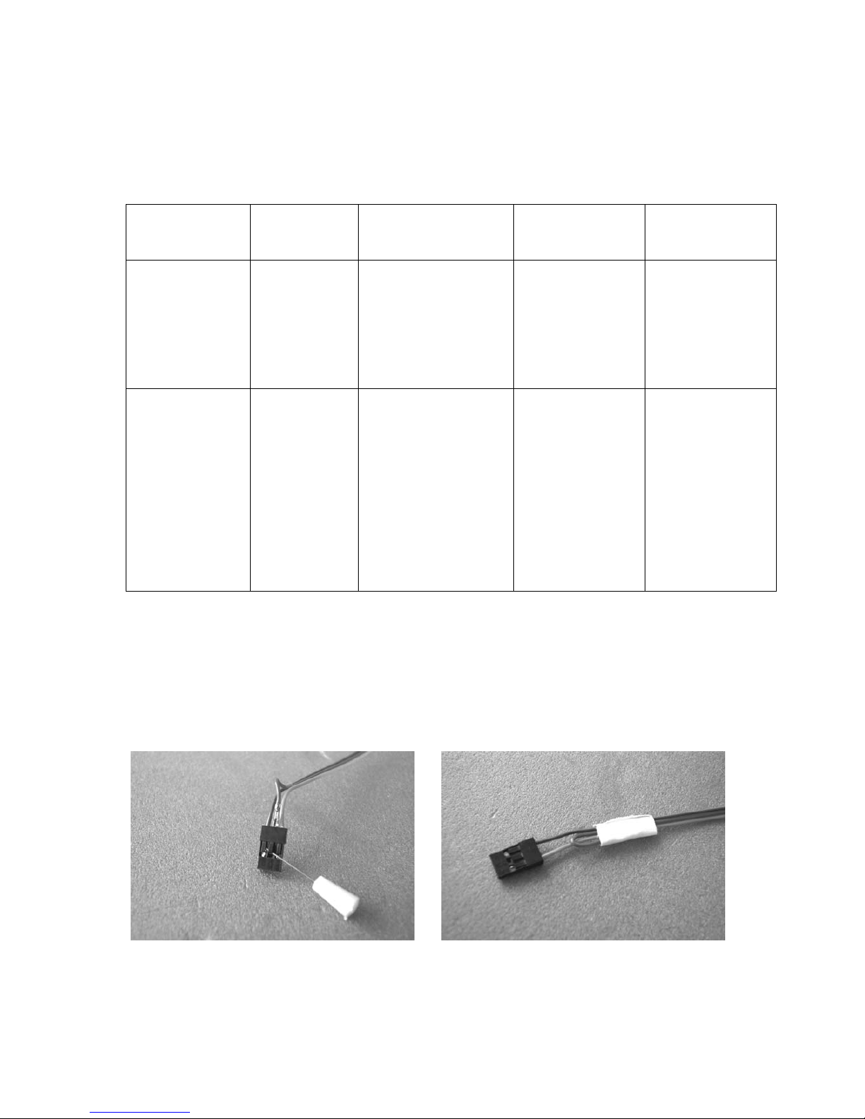
Beim Empfängeranschlusskabel des Reglers muss das rote Kabel aus dem
Kunststoffteil herausgezogen werden. Vorsichtig mit einer Stecknadel das
Sicherungsteil anheben, das Kabel herausziehen und isolieren. siehe Foto.
Page 10
RC-Funktionen Empfohlene Servos
Typ Best.-Nr. Anzahl
Seitenruder C 341 4093 2
Höhen-/Tiefenruder C 341 4093 2
Querruder C 341 4093 2
Wölbklappe C 341 4093 1
Motorschalter bei Elektroversion
Technische Daten
Elektroversion Seglerversion
Spannweite ca. 2250 mm 2250 mm
Rumpflänge ca. 1045 mm 1045 mm
Länge ü. a. ca. 1085 mm 1085 mm
Tragflächenprofil GQ/W 10% GQ/W 10%
Tragflächeninhalt ca. 42,1 dm
2 42,1 dm²
Höhenleitwerksinhalt ca. 7,8 dm2 7,8 dm2
Gesamtflächeninhalt ca. 49,9 dm2 49,9 dm2
Gewicht ca. 1640 g 1090 g
Bauanleitung
Bei Klebarbeiten darauf achten, dass die Oberfläche trocken, fett- und staubfrei ist.
Rumpf mit Höhenleitwerk in Elektroausführung
Als erster Arbeitsgang werden die Servos für das V-Leitwerk auf das Brettchen
geschraubt.
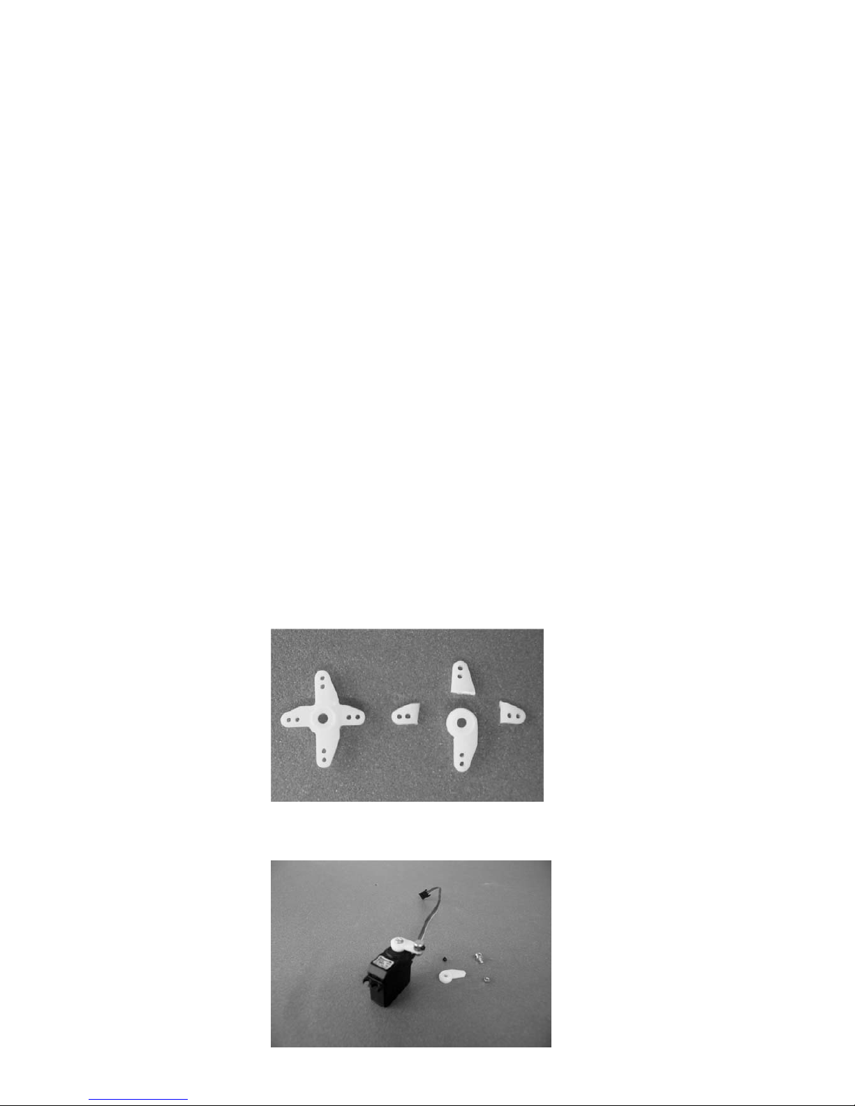
Hierzu müssen die Servohebel entsprechend dem nachfolgenden Foto bearbeitet
werden.
Die so bearbeiteten Servohebel, bei Servomittelstellung, auf die Abtriebsachse der
Servos schrauben.
Page 11
Für den Gestängeanschluss muss die äußerste Bohrung des Servohebels mit einem
Bohrer Ø2mm aufgebohrt werden. Der Gestängeanschluss muss so mittels der M2
Stoppmutter auf den Servohebeln montiert werden, dass sie sich ohne merkliches
Spiel noch leicht drehen lässt.
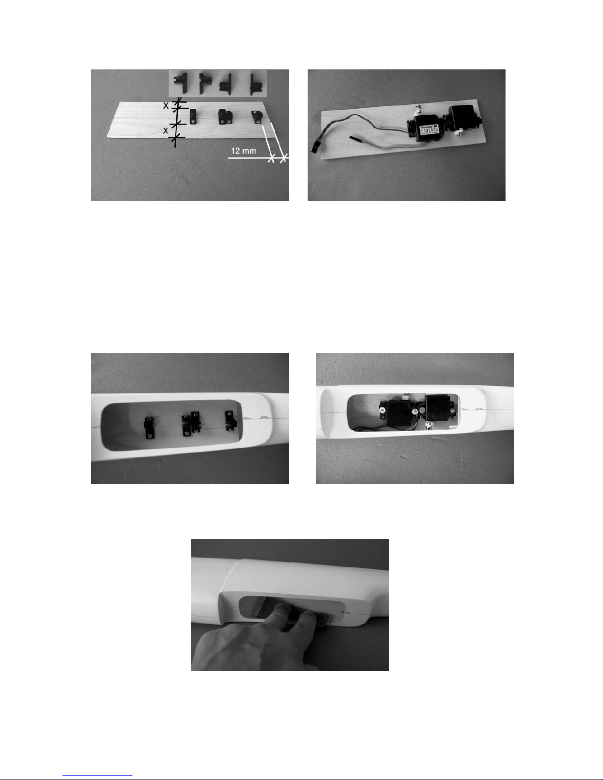
Die so vorbereiteten Servos mit den Servohalterungen (siehe Foto) auf das
Servobrettchen legen und die Befestigungsbohrungen auf das Brettchen übertragen.
Mit den beiliegenden Zylinderkopfblechschrauben vorbohren, mit Bohrer Ø1,5 mm
die Servohalterungen auf das Brettchen schrauben, mit der Unterseite des
Brettchens bündig abfeilen, da sonst der Akku beschädigt wird.
Das so vorbereitete Servobrettchen wird so in den Rumpf geklebt, dass der
Antriebsakku unter das Brettchen geschoben werden kann. Die Klebefläche im
Rumpf muss gut angeschliffen werden.
Wichtig: Unbedingt den Abstand von Servobrettchen und Rumpfboden kontrollieren.
Nach dem Trocknen des Klebstoffes können die beiden Servos in die
Servohalterungen eingesteckt und mit U-Scheiben und Blechschrauben Ø 2,2x6,5
festgeschraubt werden.
Page 12
Das V-Höhenleitwerk
Zuerst werden die beiden Höhenruder mit Klebefilmstreifen an die entsprechenden
Höhenflossen geklebt.
Wie auf dem Foto zu sehen, auf die Oberseite der Höhenflosse durchgehend einen
Klebestreifen anbringen. Jetzt das Höhenruder von unten an den Klebestreifen
kleben. Dabei ist darauf zu achten, dass sich das Ruder auf Vollausschlag befindet.
Jetzt wird das Ruder umgeschlagen, dass es auf der Oberseite aufliegt.
In dieser Position wird, wie auf dem nachfolgenden Foto zu sehen, ebenfalls ein
Klebestreifen angebracht. Hierbei ist es wichtig darauf zu achten, dass die beiden
Klebseiten der Klebestreifen zusammenkleben.
Jetzt nachdem beide Ruder befestigt sind, können die Höhenleitwerkshälften
zusammengeklebt werden. Hierbei ist es wichtig auf den Öffnungswinkel der beiden
Hälften zu achten. Er sollte ca. 110° betragen. Dies kann mit einem Geodreieck
kontrolliert werden.
Bis zum Trocknen des Klebstoffes die Teile mit zwei Federklammern z.B. Best.-Nr.
542.1 zusammenhalten.
Nach dem Trocknen des Klebstoffes auf die Unterseite der Höhenleitwerksauflage
Page 13
die Sperrholzverstärkung aufkleben und bis zum Trocknen des Klebstoffes mit
Federklammern andrücken.
Anschließend wird auf der Oberseite des Höhenleitwerks die Dreikantverstärkung
aufgeklebt. Hierzu muss die Bespannfolie entsprechend der Klebefläche von den
Höhenflossen abgezogen werden.
Mit einem Filzstift anzeichnen, etwas kleiner als die Markierung nur die Bespannfolie
einschneiden und vom Holz abziehen. Unter Zugabe von Klebstoff die
Dreikantverstärkung aufkleben und bis zum Trocknen des Klebstoffes mit
Stecknadeln fixieren.
Das Höhenleitwerk kann entweder auf den Rumpf geklebt oder, was für den
Transport besser ist, aufgeschraubt werden.
Wenn das Leitwerk aufgeschraubt wird, wie folgt vorgehen:
Page 14
Das Verstärkungsbrettchen, welches unter der Leitwerksauflage in den Rumpf
geklebt wird, mit zwei Klebestreifen, deckungsgleich, auf die Leitwerksunterseite
kleben. Das Leitwerk genau deckungsgleich mit der Rumpfauflage auf den Rumpf
legen. Jetzt können von oben die Löcher für die beiden Befestigungsschrauben
gebohrt werden. Zuerst das vordere Loch bohren. Um sicher zu sein, dass sich das
Leitwerk nicht verdreht, eine Befestigungsschraube in die Bohrung stecken.
Anschließend das hintere Loch bohren.
Jetzt das Leitwerk wieder abnehmen, Verstärkungsbrettchen lösen und auf das
Verstärkungsbrettchen zwei Spezialmuttern kleben.
Nach dem Trocknen des Klebstoffes das Brettchen in den Rumpf kleben evtl. ist
rechts und links etwas Nacharbeit nötig. Klebefläche im Rumpf gut anschleifen. Bis
zum Trocknen des Klebstoffes das Brettchen mit zwei Schrauben gegen
Verrutschen sichern. Wichtig: Darauf achten, dass kein Klebstoff in die
Gewindegänge der Schrauben kommt.
Als nächsten Arbeitsgang ist die
Torsionsfeder für die Höhenruder anzufertigen.
Page 15
40
11
11
Bei CUMULUS XXL werden die Höhenruder über Seilzug angelenkt, d.h., wenn das
Seil zieht, gehen die Ruder auf Tiefe, Höhenruder wird mittels der Torsionsfeder
erreicht.
Die Torsionsfedern müssen nach der Skizze gebogen werden (einmal spiegelbildlich).
Die beiden Enden der Torsionsfeder werden zum Einen in die Flosse zum Andern in
die Ruder gesteckt. Ca. 20 mm von Leitwerksunterkante, das eine Ende der
Torsionsfeder in die Höhenleitwerksflosse stecken, das andere Ende wird ins Ruder
gesteckt, dabei muss die Torsionsfeder um 90° verdreht werden, so dass die Ruder
auf hoch ausschlagen. Für die Torsionsfeder muss in die Flosse eine kleine Nut
geschnitten werden, damit die Ruder auch den vollen Ausschlag ausführen können.
Jetzt können die beiden Ruderhörner angeschraubt werden. Dabei ist darauf zu
achten, dass sie eine Abstand von ca. 12 mm haben, und die Einhängebohrungen
mit den Drehpunkten der Ruder übereinstimmt. Die Ruderhörner müssen
entsprechend dem Foto bearbeitet werden.
Die Befestigungsschrauben der Ruderhörner, auf der Oberseite, bündig mit den
Gegenplatten abschneiden und verschleifen.
Page 16
Die Seilzüge werden an den Ruderhörnern mittels Drahthaken eingehängt. Die Seile
an den Drahthaken festknoten und mit einem Tropfen Sekundenkleber gegen
Öffnen sichern.
Damit die Seilzuganlenkung nicht scheuern kann, werden unter dem Höhenleitwerk
und hinter der Tragflächenendkante Kunststoffröhrchen (Ø3,2x2,2x100 mm) in den
Rumpf geklebt.
Dies geschieht am einfachsten, wenn die Röhrchen auf die Seilzüge aufgefädelt
werden. Jetzt vom Rumpfende aus die Seilzüge in den Rumpf schieben. Die freien
Enden müssen vorne durch die Querbohrungen der Gestängeanschlüsse
geschoben werden. Zum Einstellen der Höhenruder müssen die Servos in
Mittelstellung gebracht werden. Hierzu muss die RC-Anlage kurz in Betrieb
genommen werden, dabei darauf achten, dass die Trimmungen am Sender sich in
Mittelstellung befinden. Jetzt die Drahthaken in die äußerste Bohrung der
Ruderhörner einhängen. Zum Festklemmen der Seilzüge in den
Gestängeanschlüssen müssen auf die Seile Aluminiumröhrchen ((Ø2x1,6x15 mm)
aufgeschoben und mit den Gewindestiften geklemmt werden.
Der Rumpfkopf
CUMULUS XXL kann in zwei Varianten geflogen werden.
1. Als reines Segelflugmodell
2. Als Elektrosegler
Die Aufstecknase kann ohne Werkzeug auf dem Flugfeld in kürzester Zeit
gewechselt werden.
Einbau des Elektromotors
Je nach verwendetem Motor müssen in den Kopfspant zwei Löcher gebohrt werden.
Wie auf dem Foto zu sehen, die Stirnseite der Kühllufteinlässe ausschneiden bzw.
ausfeilen.
Dabei darauf achten, dass die Kühlluftöffnungen am Motor mit den Kühllufteinlässen
im Rumpfkopf übereinstimmen. Beim Einbau eines Getriebeantriebes wird unter den
Motor ein Hilfsspant geklebt. Evtl. muss der Spant an die Rumpfinnenkontur
angepasst werden.
Beim Einschrauben des Getriebemotors muss zwischen Motor und Kopfspant der 3
mm dicke Rundspant gelegt werden, da sonst der Abstand zwischen Rumpfkopf und
Spinnerrückseite zu groß ist.
Page 17

Für die Befestigung der Aufstecknase müssen rechts und links, durch Aufstecknase
und Rumpf, Löcher gebohrt werden Ø 5,6 mm. Die Maße dafür aus dem Foto
entnehmen und auf die Aufstecknase Rumpf übertragen.
Øca.5,6
Jetzt werden die Sicherungsbrettchen eingeklebt. Diese bestehen aus jeweils einem
Sperrholzstreifen und einer Inbusschraube M3x6.
Nach den Maßangaben auf dem Foto, für die Inbusschrauben M3x6, in die
Sperrholzstreifen Löcher bohren.
Die beiden Sperrholzstreifen werden so in den Rumpf geklebt, dass der
Schraubenkopf ohne zu streifen in Bohrungen einfedern kann.
Page 18
Dabei unbedingt darauf achten, dass die Streifen nicht auf der ganzen Länge
festgeklebt werden. Es genügt, wenn die Streifen auf einer Länge von ca. 10-15 mm
festgeklebt sind. Der Sperrholzstreifen muss als Feder funktionieren.
Um den Empfängerakku einschieben zu können, muss der Rumpf vorne
entsprechend ausgeschnitten werden.
Durch leichtes drücken auf die beiden Schraubenköpfe wird der Rumpfkopf
entriegelt und kann abgezogen bzw. aufgeschoben werden.
Die Klappluftschraube entsprechend der Luftschraubenanleitung montieren.
Die Abschlussarbeiten am Rumpf sind bohren des Loches für den Haltedübel und
für die Befestigungsschraube.
Wie folgt vorgehen: Für den Haltedübel in Rumpfmitte, siehe Foto, ein Loch mit
Ø4 mm bohren. Die Position ist auf dem Foto zu sehen, evtl. ist mit einer kleinen
Rundfeile nacharbeiten.
Page 19

Das Loch für die Befestigungsschraube der Tragflächen mit zur Hilfenahme des
Tragflächenmittelteils in den Rumpf bohren.
Jetzt kann die Befestigungsmutter in den Rumpf geklebt werden.
Wegen dem Profilverlauf ist es notwendig, die Mutter mit einem Stück Dreikantleiste
in den Rumpf zu kleben (UHU plus).
Dabei darauf achten, dass das spitze Ende nach vorne zeigt, evtl. ist etwas
Nacharbeit an der Dreikantleiste notwendig, dass sie flächig aufgeklebt werden
kann. Bis zum Aushärten des Klebstoffes die Muter mit einer Schraube an den
Rumpf ziehen. Wichtig: es darf kein Klebstoff in die Gewindegänge kommen.
In die Bohrung in der Nasenleiste des Tragflächenmittelteils einen Ø 4 mm Dübel
stecken. Tragflächenmittelteil so auf den Rumpf setzen, dass zum Einen der Dübel
in die Bohrung eingreift, zum Andern das Tragflächenmittelteil mit der
Rumpflängsachse einen rechten Winkel bildet. Wenn dies sichergestellt ist, kann mit
einer Bohrmaschine das Loch für die Befestigungsschraube auf den Rumpf
übertragen werden. Bohrer rechtwinkelig zur Tragflächenoberseite ausrichten. Auch
hier wird ein Bohrer mit Ø 4 mm benötigt.
Page 20

Einbau von EIN/AUS Schalter und Ladebuchse
Wie auf dem Foto zu sehen, den Schalter und die Ladebuchse in die
Rumpfseitenwand einbauen, hierzu entsprechende Öffnungen in den Rumpf feilen.
Die Tragfläche
Die Arbeiten an der Tragfläche beschränken sich auf das Anbringen der Wölbklappe
und der Querruder sowie den Einbau der Servos.
Zuerst werden die Wölbklappe und die Querruder, wie bereits beim Höhenleitwerk
beschrieben, befestigt.
Bei der Wölbklappe muss darauf geachtet werden, dass sie sich später durch das
Servo sowohl nach unten als auch nach oben fahren lässt. Dafür ist die Wölbklappe
einseitig konisch, d.h. ,die Stirnseite der Wölbklappe bildet im Schnitt gesehen mit
einer Längsseite einen rechten Winkel, d.h. die Wölbklappe muss so angeklebt
werden, dass dieser rechte Winkel auf der Oberseite ist.
Als nächsten Arbeitsgang wird das Wölbklappenservo eingebaut.
Hierfür muss an der entsprechenden Stelle die Bespannfolie aus dem
Tragflächenmittelteil herausgeschnitten werden. Am besten 4-5mm kleiner
ausschneiden und die noch stehende Bespannfolie nach innen an die Rippen bzw.
Holm anbügeln.
Zum Einkleben des Servos wird diese mit Schrumpfschlauch eingeschrumpft.
Dies hat den Vorteil, dass es bei einer mögliche Reparatur leicht wieder auszubauen
ist. In diesem Fall muss nur der Schrumpfschlauch aufgeschnitten, und das Servo
kann entnommen werden.
Das Servo wird so in das Tragflächenmittelteil geklebt, dass die Abtriebswelle
parallel zu der Endkante verläuft, siehe Foto. Hebelarm des Servohebels 13 mm
Einhängebohrung mit Ø2 mm aufbohren.
Page 21
Das Anschlusskabel des Servos aus der hinteren Bohrung in der unteren
Beplankung herausführen.
Für den Anschluss der beiden Querruderservos müssen in das Tragflächenmittelteil
rechts und links je ein Verlängerungskabel (Best.-Nr. 3935.65) eingezogen werden.
Hierzu müssen die Steckerkunststoffteile vorsichtig mit einer Nadel von den Kabeln
abgenommen werden. Siehe Foto.
Die freien Kontaktenden mit einem Stück Klebeband zusammenwickeln.
Jetzt kann das Verlängerungskabel von der Abschlussrippe aus in das
Kunststoffröhrchen eingeschoben oder mittels eines Ø0,8 mm Stahldrahtes
eingezogen werden.
Anschließend das Kunststoffteil wieder auf die Kontakte aufschieben, wichtig: auf
richtige Polung achten!
Page 22

Wie aus den Fotos zu ersehen, fluchtend mit dem Servohebel, in die Wölbklappe ein
Ø 3 mm Loch bohren.
Den Stift des Ruderhorns entsprechend der Dicke der Wölbklappe kürzen, die
äußerste Bohrung mit einem Bohrer Ø 1,6 mm aufbohren und, wie auf dem Foto zu
sehen, in die Wölbklappe einkleben. Hierzu die Bespannfolie entsprechend der
Klebefläche von der Wölbklappe ablösen.
Das Anlenkgestänge besteht aus einem M2 Gabelkopf und einer M2
Gewindestange. Gabelkopf ganz auf die Gewindestange aufdrehen. Gabelkopf in
Ruderhorn einhängen, jetzt kann die genaue Länge angezeichnet werden. Hierzu
muss der Servohebel um zwei Rasten, außer der Mitte der Verzahnung, in Richtung
Endleiste verstellt werden. Dazu muss die RC-Anlage kurz in Betriebgenommen
werden. Zum Einhängen des Gestänges am Servohebel wird dieses mit einer
Abkröpfzange, z.B. Best.-Nr. 5732, z-förmig abgekröpft.
Page 23
Für das Fliegen muss später die RC-Anlage entsprechend den angegebenen
Ruderausschlägen eingestellt werden.
Jetzt kann die Servoabdeckung angepasst und aufgeklebt werden.
Das Ankleben der Abdeckung kann mit Klebstoff z.B. UHU Alleskleber Kraft oder
wie auf dem Foto zu sehen, mit einem Klebestreifen erfolgen.
Als nächster Arbeitsgang werden die beiden Querruderservos eingeklebt.
Wie bei der Wölbklappe beschrieben, wird auch hier das Servo in Schrumpfschlauch
eingeschrumpft, in Neutralstellung gebracht und der Servohebel aufgeschraubt und,
wie auf dem Foto zu sehen, in die Ansteckfläche eingeklebt.
Für das Ruderhorn, fluchtend zum Servohebel, ein Ø 3mm in die Querruder ca. 9
mm hinter der Drehachse bohren. Den 3mm Stift des Ruderhorns entsprechend der
Querruderdicke kürzen, Bespannfolie der Größe der Klebefläche von den
Querrudern ablösen und Ruderhorn einkleben.
Das Anlenkgestänge wie bei der Wölbklappe anfertigen. Bei Servo-Mittelstellung
müssen auch die beiden Querruder sich in Mittel-/Neutralstellung befinden.
Zum Schluss werden noch die Servoabdeckungen angepasst und aufgeklebt.
Page 24

Als Abschlussarbeit am Modell ist das Dekor aufzukleben. Hierzu die einzelnen
Segmente, mit einer Schere möglichst passgenau, ausschneiden.
Beim Aufkleben der Kabinenhaubenandeutung wie folgt vorgehen. Die Klebefolien
ohne die Schutzfolien abzuziehen, auf den Rumpfkopf legen und mit einem Bleistift
Hilfspunkte auf den Rumpfkopf anzeichnen. Das Ankleben der
Kabinenhaubenandeutung gelingt an besten von unten zur Mitte zu. Kleine
Differenzen an der Stoßstelle müssen mit einem scharfen Balsamesser beglichen
werden.
Der Einbau des Hochstarthakens
Sollte CUMULUS XXL als reines Segelflugmodell geflogen werden, besteht die
Möglichkeit, ihn im Hochstart auf Höhe zu bringen. Dazu wird in den Rumpfboden
ein Kunststoffhochstarthaken eingebaut.
Zum Anschrauben des Hochstarthakens zwei Löcher Ø 3mm in den Rumpfboden
bohren.
Die Maße aus dem Foto entnehmen. Das Maß, ca. 47 mm, zeigt den Punkt an dem
später der Hochstartring am Haken anliegt.
Wichtig: der Haken kann nur eingeschraubt werden, wenn CUMULUS XXL als
reines Segelflugmodell eingesetzt wird, da der Antriebsakku für den Elektromotor
nicht mehr eingeschoben werden kann.
Page 25

Der Zusammenbau von CUMULUS XXL
Höhenleitwerk mit den beiden Senkkopfschrauben auf den Rumpf schrauben.
Ruder nach unten drücken und die Haken der Anlenkschnüre einhängen.
Servokabel an dem Empfänger anschließen, Tragflächenmittelteil mit dem Dübel in
die Bohrung im Rumpf stecken und mit der Senkkopfschraube und Anpressplatte
auf dem Rumpf befestigen.
Mit den V-Form gebogenen Stahldrähten die beiden Ansteckflächen rechts und links
an das Mittelteil stecken. Querruderservokabel mit dem Verlängerungskabel
zusammenstecken. Die beiden Ansteckflächen mit Klebstreifen auf der Ober- und
Unterseite gegen Lösen sichern.
Das Auswiegen von CUMULUS XXL
Das komplett ausgerüstete Modell, sprich flugfähig, rechts und links neben dem
Rumpf, ca. 80 - 86 mm hinter der Nasenleiste, unterstützen. Jetzt sollte das Modell
sich waagerecht auspendeln, bzw. die Rumpfnase leicht nach unten zeigen. Dies
kann durch Verschieben des Antriebsakkus erreicht werden. Bei richtiger
Akkuposition wird in den Rumpf ein Anschlag geklebt (Balsazuschnitt).
Für die ersten Flugversuche sollte der Schwerpunkt an die vordere angegebene
Position gelegt werden.
Vor dem ersten Flug müssen sämtliche Ruder, bei Sendertrimmung in Mitte, genau
auf Mittelstellung (Neutralstellung) gebracht werden.
Ruderausschläge
Querruder plus 22 mm minus 8 mm
Höhenruder plus 15 mm minus 12 mm
Seitenruder plus 15 mm minus 12 mm
Wölbklappe plus nach unten 3 mm minus nach oben 1,5 mm
Butterfly-Stellung
Querruder nach oben 28 mm
Wölbklappe nach unten 35 mm
Höhenruder nach unten 5,5 mm
Wichtig:
Bei der Montage der Gestänge grundsätzlich sorgfältig darauf achten, dass diese
leicht laufen, ihren vollen steuerbaren Weg – einschließlich Trimmung – ausführen
können und keinesfalls mechanisch begrenzt werden.
Bei Bewegen des Steuerknüppels nach rechts, muss das rechte Höhenruder nach
unten und das linke nach oben ausschlagen. Beim Bewegen des
Höhen/Tiefenruder-Knüppels nach hinten, sprich zum Bauch, müssen die beiden
Ruder nach oben ausschlagen (nach vorne = unten). Beim Bewegen des QuerruderSteuerknüppels nach rechts, muss das rechte Querruder nach oben, das linke nach
unten ausschlagen. Beim Bewegen des Butterfly-Steuerknüppels nach hinten, sprich
zum Bauch, müssen die Querruder nach oben und die Wölbklappe nach unten
ausschlagen. Die Wölbklappe wird am besten über einen Schieber betätigt, bei dem
der Weg elektronisch begrenzt wird, so dass bei vollem Weg des Schiebers die
angegebenen Wege erreicht werden.
Nun bleibt nur noch viel Spaß und Freude beim Fliegen mit Ihrem CUMULUS XXL
zu wünschen. Ihr Team !
Page 26

to Order No. 4546
CUMULUS XXL
BUILDING INSTRUCTIONS
For electric power system and 8 cells
This model requires a 5-function radio control system.
Introduction
This model is highly pre-fabricated, enabling the beginner to get flying with the minimum delay.
The machine’s speed under power is carefully matched to its gliding speed, i.e. the difference in
airspeed is hardly perceptible, and this makes learning to fly much easier for the beginner.
The low wing loading and airspeed means that the CUMULUS XXL should not be flown in winds
above moderate until you have flown the machine for several hours in calmer weather to familiarise
yourself with its handling.
The CUMULUS XXL is not designed or stressed for aerobatics, but loops and tightly banked turns are
well within its capability provided that you are smooth and gentle with the controls.
The CUMULUS XXL is very responsive to thermals and circles very well. If the model should climb to
an uncomfortable altitude, perhaps when you contact a strong thermal, the butterfly (crow) setting of
the ailerons and camber-changing flaps provides a reliable means of losing height quickly.
Caution: this model is not a toy!
If you have little or no experience with powered model aircraft of this type, please enlist the help of a
seasoned model flyer who can advise and support you. Attempting to fly the model without any prior
experience could easily result in personal injury; please keep your safety and wellbeing in mind.
Important: before you start construction
Even if you have already built many RC models please read right through these instructions very
carefully, and check that all the kit components are actually present before starting construction. We
have invested considerable time and trouble in making assembly as easy as possible, without
compromising safety in any way.
Note regarding the film covering
Minor creases or bubbles may develop in the film covering due to major fluctuations in weather
conditions (temperature, humidity etc.); in rare cases you may even find a slight warp in a component.
These minor faults are in the nature of film-covered built-up wooden structures, and can easily be
corrected using a heat gun, as commonly used for modelling.
Creases: Blow warm air over the area and rub down with a soft cloth.
Wing warp: Hold the panel twisted gently in the opposite direction to the warp, and apply warm
air to remove the creases from the covering.
Caution! do not heat the film more than is absolutely necessary. If the air or the iron is too hot, the film
may melt and holes may be formed.
This model is highly pre-fabricated and can be built in a very short time. However, the work which you
have to carry out is important and must be done carefully. The model will only be strong and fly well if
you complete your tasks competently - so please work slowly and accurately.
Page 27

Notes on operating the CUMULUS XXL
Be sure to read right through the instructions covering assembly and operation of your model
before you attempt to operate it for the first time. You alone are responsible for the safe
operation of your radio-controlled model. Young people under 12 years of age should only be
permitted to build and fly this model under the instruction and supervision of an adult who is
aware of the hazards involved in this activity.
These operating instructions should be stored in a safe place, and must be handed on to the
new owner if you ever dispose of the model. If you have questions or queries about operating
this RC model aircraft safely, please contact your local model shop in the first instance, where
the staff will be pleased to advise you.
Radio-controlled model aircraft are highly demanding and potentially dangerous objects, and
require a high level of specialised knowledge, skill and an awareness of responsibility from the
operator.
In legal terms our models are classed as aircraft, and as such are subject to legal regulations
and restrictions which must be observed. Our brochure “Luftrecht fuer Modellflieger” (Aviation
Law for Modellers) is available under Order No. 8032, and contains a summary of all these
rules. Your local model shop should have a copy which you can read. There are also Post
Office regulations concerning your radio control system, and these must be observed at all
times. Refer to your RC system instructions for more details.
Be sure to use only those parts included in the kit, together with other genuine Graupner
accessories and replacement parts as recommended expressly by us. Even if you change a
single component of the power system you can no longer be sure that the system will work
reliably, and such changes also invalidate your guarantee.
Use only matching polarised connectors. All high-current cables and connectors must be
insulated carefully to eliminate the risk of short-circuit; this also includes the flight battery if
you assemble the pack yourself. Never combine plugs and sockets of different types, e.g. goldcontact with tin-contact, as such connections are never reliable in the long-term.
If you are using a motor switch or speed controller with an integral receiver power supply (BEC
system), be sure to use only Graupner gold-contact connectors.
Avoid short circuits and reverse polarity at all times.
The high energy density of NC batteries involves a permanent danger of fire and even
explosion.
A radio-controlled model aircraft can only work properly and fulfil your expectations if it is built
very carefully and in accordance with the building instructions. If you wish to avoid injuring
people and damaging property it is essential to be careful and painstaking at all stages of
building and operating your model. Nobody would climb into a full-size aircraft and try to fly it
without completing a course of training first. Model flying is just such a skill, and has to be
learned in exactly the same way.
However, as manufacturers we have no means of influencing the way you build and operate
your RC model aircraft, and for this reason we can do no more than point out the hazards
expressly. We accept no further liability.
If you need help, please enlist the aid of an experienced modeller, join a model club or enrol at
a model flying training school. Model shops and the specialist model press are also good
sources of information. The best course is always to join a club and fly at the approved model
flying site.
You alone are responsible for the safe operation of your RC powered glider.
If you have queries concerning safety relating to RC model aircraft, please ask your local
model shop for advice, where the staff will be glad to help.
Adhesives and paints contain solvents which may be hazardous to health under certain
circumstances. Read and observe the notes and warnings supplied by the manufacturer of
these materials.
The operator of the model must be in full possession of his or her bodily and mental faculties.
As with car driving, operating a model aircraft under the influence of alcohol or drugs is highly
dangerous and not permissible under any circumstances.
Page 28

Make sure that all passers-by and onlookers are aware of the hazards involved in the operation
of your model. Remind them to keep a safe distance from the model: at least 5 m behind the
rotational plane of the propeller.
Keep a safe distance between your model and other people or objects at all times. Never fly
low over people or directly towards them.
Radio-controlled models should only be flown in temperatures within the range -5° to +35°C.
More extreme temperatures can lead to changes in battery capacity, material characteristics,
the strength of glued joints and other unwanted effects.
All model flyers should behave in such a way that the danger to people and property is
minimised. Never act in any way which will disturb other flyers or prevent safe, orderly flying at
the site.
Don’t operate your model in the vicinity of overhead power cables, industrial sites, residential
areas, public roads, squares, school playgrounds, public parks or sports fields etc.
Don’t ignore our warnings. They refer to hazardous materials and processes which, if ignored,
can result in fatal injury or serious damage to property.
Propellers and other rotating parts which are powered by a motor represent a permanent
hazard and present a real risk of injury. Don’t touch them with any part of your body. For
example, a propeller spinning at high speed can easily slice off your finger.
Keep well clear of the rotational plane of the propeller. You never know when some part (or the
whole propeller) may come loose and fly off at high speed, hitting you or anybody else in the
vicinity; this can result in serious injuries. Never touch the revolving propeller with any object.
Ensure that there is no chance of any object obstructing the propeller and preventing it
turning.
Take care with loose clothing such as scarves, loose shirts etc. Flapping cloth can easily be
sucked into the area of the propeller and then get tangled in the blades. This is extremely
dangerous.
Every time you intend flying the model, check carefully that all parts connected to it are
working correctly, including propellers, RC components, etc. Everything must be properly
located and firmly secured. Check for possible damage, and do not fly your model unless you
are confident that everything is in perfect order.
Whenever you are working on the motor, make sure that you are on a safe surface and cannot
slip. Wear high-grip shoes such as trainers.
Satisfy yourself that your frequency is vacant before you switch on. Radio interference caused
by unknown sources can occur at any time without warning. If this should happen, your model
will be uncontrollable and completely unpredictable. Never leave your radio control system
unguarded, as other people might pick it up and try to use it.
Do not switch on an electric motor unless you are sure that there is nothing in the rotational
plane of the propeller. Don’t attempt to stop the spinning propeller with your hands. Never run
an electric motor with a propeller fitted unless it is firmly anchored.
If you are to fly your model safely and avoid problems it is essential that you are aware of its
position and attitude throughout each flight - so don’t let it fly too far away! If you detect a
control problem or interference during a flight, immediately land the model to prevent a
potential accident. Models must always give way to full-size aircraft. Take-off and landing
strips should be kept free of people and other obstacles.
Your RC system can only work reliably if the batteries are kept fully charged.
Page 29

Never use batteries which are hot, faulty or damaged. Always heed the instructions provided
by the battery manufacturer.
Before every flight be sure to carry out a range check, and ensure that all functions are
working correctly. Note in particular that the motor control function on the transmitter must
first be set to the OFF position before you switch on the system. Always switch on the
transmitter first, then the receiving system, to eliminate any chance that the motor will burst
into life unexpectedly. When switching off, reverse the order: receiving system first, then the
transmitter.
Check that the control surfaces move in the direction which corresponds to the stick
movement:
If you move the rudder stick to the right, the right-hand elevator should move down and the
left-hand elevator up.
Pull the elevator stick back towards you, and both elevators should rise.
Always move the transmitter sticks smoothly - never abruptly.
After each session remove the battery from the model and store it in a discharged state
(approx. 0.9 V per cell) at a temperature of about +5° to +25°C. Batteries should be kept out of
the reach of children at all times.
Please don’t misunderstand the purpose of these notes. We only want to make you aware of
the many dangers and hazards which can arise if you lack knowledge and experience, or work
carelessly or irresponsibly. If you take reasonable care model flying is a highly creative,
instructive, enjoyable and relaxing pastime.
Building and flying the CUMULUS XXL
Before you start building the model:
If you are buying a radio control system for this model, check that the transmitter and receiver are
suitable for model aircraft and bear the standard type-approval sticker.
The frequency bands used for radio control systems are shared by other radio equipment and radiofrequency apparatus, so we cannot guarantee that you will not suffer interference when using your
system.
Individual countries may require you to pay for a licence to operate your radio control equipment. In
Great Britain no fee is payable to operate 35 MHz radio control equipment, but you should check with
your local authority for any by-laws restricting its use. This information may not apply to other
countries.
Your local Post Office or model shop will be able to provide more information on this subject.
During construction
RC components and linkages must be installed when mentioned in the appropriate stage of
construction. Fitting these parts later will be more difficult, and could even be impossible.
The building instructions
The instructions reflect the sequence of assembly and correspond to the sequential part numbers
wherever possible. The following notes are intended to provide additional explanatory information. All
die-cut wooden parts should be carefully separated from their sheets using a sharp balsa knife, e.g.
Order No. 986, and all rough edges sanded off.
All parts must be trial-fitted “dry” (without glue) first, and any trimming carried out. Note that some
parts are deliberately provided oversize. We suggest that you lay out the kit components
corresponding to the major sub-assemblies: fuselage, wing panels, tail etc., according to part number.
To build the model you will need a flat, perfectly straight softwood building board of adequate size, e.g.
the System Building Board, Order No. 645, or the Balsa Jig Board, Order No. 503.
Experienced builders may wish to deviate from the recommended sequence of operations; this is left
up to the modeller’s discretion.
Page 30

Refer to the plan and parts list constantly when building the model.
Note that balsa knives, pins, the ends of thin wire etc. have sharp points and edges; always handle
them carefully to avoid injury.
Keep tools, adhesives and paints out of the reach of children.
When using solvent-based glues make sure that your building room is well ventilated.
Take left-over paint and adhesives to your local toxic waste collection centre.
A large, unobstructed working area is a great advantage for all modelling activities.
If you are not sure of any procedure in building this model, ask the advice of an experienced model
builder.
If you have to handle lead ballast be sure to wash your hands thoroughly with soap and water
afterwards.
Flying the model
Never fly your CUMULUS XXL in a nature reserve or any other protected site. Please don’t disturb the
animals and plants which live in the countryside.
Trees and bushes are the natural habitat of many birds, and also serve as nesting sites and general
protection for them.
Exhausted dry cells and rechargeable batteries must not be thrown in the household waste, as they
contain toxic materials. Take all batteries back to the model shop, or to your local toxic waste
collection centre.
Tools required to build the CUMULUS XXL
Pencil (HB lead), setsquare, tape measure or metre rule, household scissors, sharp narrow-bladed
knife, e.g. balsa knife, Order No. 986, small electric drill, set of twist drills (1.5, 2.0, 2.5, 3, 4, 5.5, 10
mm Ø), cross-point screwdriver, e.g. Order No. 810, allen key, Order No. 10, thread-lock fluid, Order
No. 952, flat-nose pliers, spring clamps, Order No. 542.1.
Gluing different materials
The following table provides a few typical examples of glued joints. It is only a guideline, and is not
intended to be comprehensive.
Material Typical joint Adhesive
Plywood to GRP Servo plate to UHU plus endfest
GRP fuselage 950.15
Plastic to balsa Horn to camber- UHU hart
changing flap 534.10
Plastic to plastic Heat-shrink sleeve to UHU cyano-acrylate
servo well cover 1098
Note
Areas of the fuselage which are to be glued should be rubbed down with fine-grit abrasive paper to
remove any lingering traces of mould release agent. Aim at reducing the glossy surface to a matt
finish, especially when dealing with smooth, shiny GRP parts, otherwise there is little chance of a
durable glued joint.
Important: don’t use more glue than is necessary, as excess adhesive just adds unnecessary weight.
Please read the instructions supplied by the adhesive manufacturer before using any particular glue.
For more information on adhesives see the main FS catalogue.
Radio control system for the CUMULUS XXL
We suggest the following items as the minimum equipment for this model:
Page 31

For the electric glider version
1 mc-12 radio control set on the 35 MHz band
e.g. Order No. 4724 or 4724.B
1 2-channel switch module Order No. 4171
5 C 341 ECO mini-servo Order No. 4093
1 C 12 miniature receiver Order No. 3175
1 VARTA 8/600 RX transmitter battery Order No. 3408
1 SANYO 4KR-1400 AE receiver battery Order No. 2523
3 Servo extension lead Order No. 3935.11
2 Servo extension lead Order No. 3935.65
1 Folding ferrite ring Order No. 98516
For the glider version
1 mc-12 radio control set on the 35 MHz band
e.g. Order No. 4724 or 4724.B
5 C 341 ECO mini-servo Order No. 4093
1 SANYO 4N800RX receiver battery Order No. 3454
1 VARTA 8/600 RX transmitter battery Order No. 3408
3 Servo extension lead Order No. 3935.11
2 Servo extension lead Order No. 3935.65
1 Folding ferrite ring Order No. 98516
We deliberately recommend rechargeable batteries for the receiver and transmitter as they provide
the broadest margin of safety.
Please refer to the main FS catalogue for details of battery chargers.
Electric power system and accessories
Motor Suppressor Folding propeller Flight battery Speed
controller capacitor or switch
Order No. Order No. Order No. Order No. Order No.
SPEED 600 3588 CAM FOLDING ECO POWER SOFT Switch
18
ECO 7.2 V PROP 23 x 12 cm 9.6 V/1.5 Ah 2866
3323 1335.23.12 2497 or
or POWER V 18
ECO POWER 2859
9.6 V/2.1 Ah
2483
SPEED GEAR Not CAM GEAR PROP SANYO Integral with
600 Plus 8.4 V required 30 x 25 cm 9.6 V/2.3 Ah motor
6326 1311.30.25 2474
or
GMVIS
9.6 V/3.3 Ah
2474.S8
or
ECO POWER
9.6 V/2.1 Ah
2483
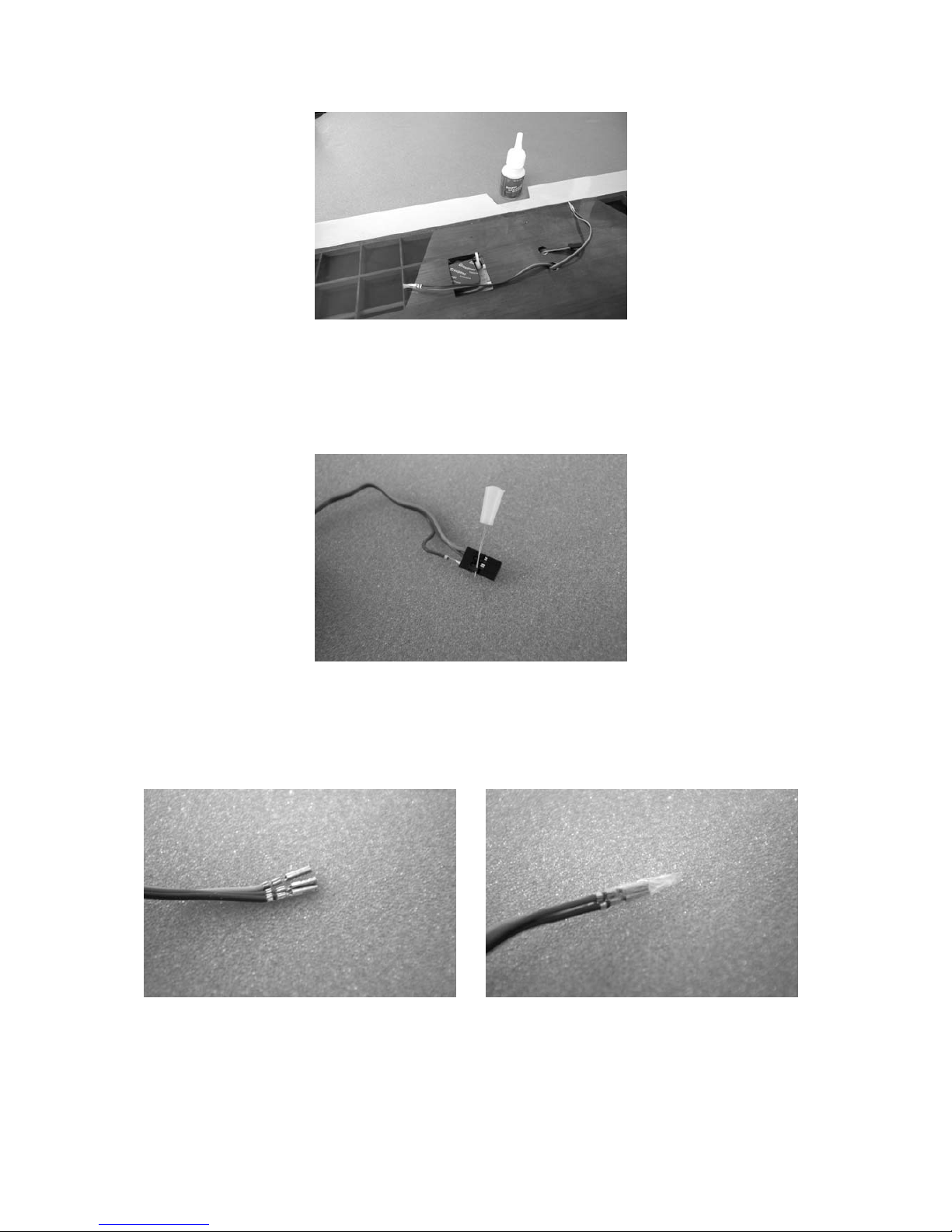
As the specified speed controller includes a BEC circuit, the red wire must be disconnected from the
receiver plug attached to the controller. Carefully raise the latch with a pin as shown, withdraw the
wire and insulate it with tape as shown in the photo.
RC functions Recommended servos
Type Order No. No. required
Rudder C 341 4093 2
Elevator C 341 4093 2
Ailerons C 341 4093 2
Camber-changing flaps C 341 4093 1
Page 32

Electric version: motor
Specification Electric Glider
Wingspan approx. 2250 mm 2250 mm
Fuselage length approx. 1045 mm 1045 mm
Overall length approx. 1085 mm 1085 mm
Wing section GQ/W 10% GQ/W 10%
Wing area approx. 42.1 dm² 42.1 dm²
Tailplane area approx. 7.8 dm² 7.8 dm²
Total surface area approx. 49.9 dm² 49.9 dm²
Weight approx. 1640 g 1090 g
Building instructions
Note that all surfaces to be glued must be dry and free of grease and dust.
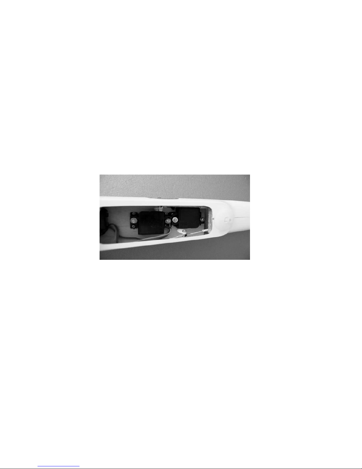
Fuselage and tailplane - electric version
The first step is to screw the V-tail servos to the servo plate.
Cut down the servo output arms as shown in the photo below.
Set the V-tail servos to neutral from the transmitter and fit the trimmed output arms on the output
shafts. Fit the retaining screws.
The pushrod connectors must be mounted on the servo output arms using M2 self-locking nuts;
ensure that they swivel freely but without lost motion. Place the prepared servos and servo mounts
(see photo) on the servo plate and mark the position of the retaining screws on the plate.
Drill 1.5 mm Ø pilot-holes in the servo plate, and screw the servo mounts to the plate using the
cheesehead self-tapping screws supplied. File off the screw ends flush with the underside of the servo
plate, otherwise the sharp ends will damage the flight battery.
Glue the prepared servo plate in the fuselage, checking that the flight battery fits underneath it.
Remember to roughen the joint surface of the fuselage thoroughly before applying the glue.
Important: be sure to check the distance between servo plate and fuselage floor. Allow the glue to
cure fully, then fit the two servos in the servo mounts and secure them using 2.2 Ø x 6.5 mm selftapping screws.
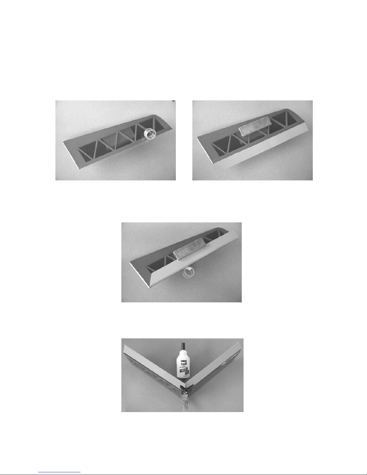
The V-tail
The first stage here is to attach the elevators to the fixed panels using strips of adhesive tape.
Apply a full-length strip of tape to the top surface of the tailplane shown in the photos, leaving half its
width projecting, then offer up the elevator to the tailplane holding the panel at the “full down” position,
and rub the tape down onto the elevator.
Now fold the elevator panel over, so that it rests flat on the top of the tailplane.
In this position apply a second strip of adhesive tape as shown in the photo below. It is important that
the two strips of tape should join in the middle, as this ensures a secure hinge.
Once both elevators have been attached, the tailplane panels can be glued together. It is important to
join them at the correct included angle, which should be about 110°; this can be checked with a
setsquare.
Hold the panels together using two spring clamps (e.g. Order No. 542.1) while the glue is drying.
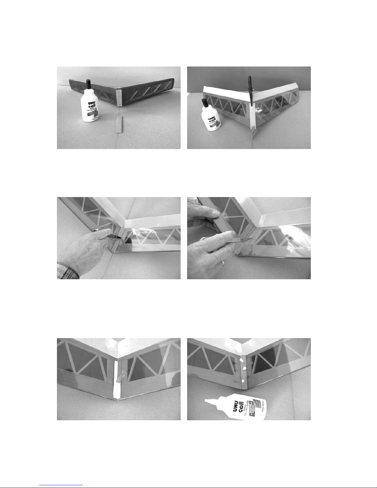
When the adhesive has hardened fully glue the plywood reinforcement to the underside of the
tailplane mount and use the spring clamps again to hold it in position while the glue dries.
The last step is to glue the triangular reinforcement to the V-joint in the top of the tailplane. Start by
removing the covering film over the joint surface of the tailplane roots.
Page 33

This is done by marking the outline of the triangular reinforcement on the film, then cutting very lightly
just inside the marked line. Peel off the covering film. Glue the triangular reinforcement to the tailplane
and pin it in place while the glue hardens.
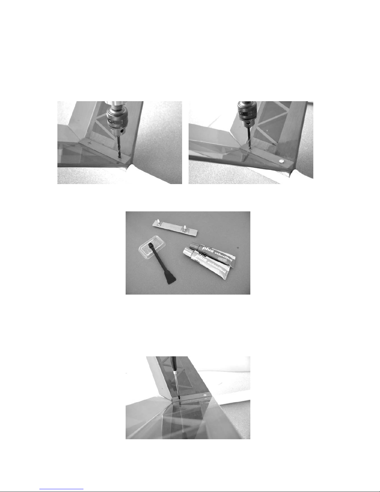
The tailplane can either be glued permanently to the fuselage or screwed in place; the latter has
advantages when transporting the model.
If you wish to screw the tailplane to the fuselage, this is the procedure:
Locate the reinforcing plate which is to be glued to the underside of the tailplane mount inside the
fuselage, and stick it temporarily to the underside of the tailplane using two strips of tape; check that
the edges are flush. Now place the tailplane on the fuselage, with the edges of the reinforcing plate
flush with the fuselage tailplane mount. The holes for the two retaining screws can now be drilled from
above. Drill the front hole first, then fit one retaining screw in that hole to ensure that the tailplane does
not twist out of position before drilling the rear hole.
Now remove the tailplane from the fuselage, release the reinforcing plate and epoxy two captive nuts
to the plate.
The plate can be glued in the fuselage when the epoxy has cured. Check the fit beforehand, as it may
be necessary to trim the plate slightly on both sides to conform with the fuselage. Roughen the joint
surface inside the fuselage thoroughly. Fit two screws into the captive nuts from above to prevent the
plate shifting while the glue hardens. Important: take care not to allow any glue onto the threaded part
of the nuts or screws.
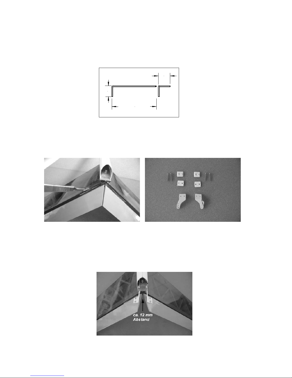
The next step is to prepare the torsion springs for the elevators.
The V-tail panels of the CUMULUS XXL are actuated by pull-cables, i.e. pulling the cables moves the
elevators to the “down” position, and torsion springs pull them to the “up” position.
Bend the torsion springs to the shape shown in the drawing below, taking care to produce a handed
pair.
The two ends of each torsion spring are fitted as follows: one end fits in the tailplane panel, the other
in the elevator. Push the one end of the torsion spring into the tailplane at a point about 20 mm from
the bottom edge of the panel, and then twist the torsion spring through 90° and insert the other end
into the elevator, so that the tension in the spring moves the elevator to the up position. You will need
to cut a small notch in the tailplane for the torsion spring, so that the elevators are not obstructed at full
movement.
The two horns can now be screwed to the elevator panels. They should be spaced about 12 mm
apart, and the linkage holes should line up with the pivot axis of the elevators. Trim the horns to the
shape shown in the photo.
Cut off the excess screw length on the top surface flush with the spreader plates, and sand the ends
smooth.
approx. 12 mm spacing
The pull-cables are connected to the horns by means of wire hooks. Tie the cables to the wire hooks
and apply a drop of cyano to them to prevent them coming adrift.
To avoid the risk of the pull cables chafing, they run in plastic sleeves (3.2 Ø x 2.2 Ø x 100 mm) fitted
in the fuselage. The sleeves are installed below the tailplane and aft of the wing trailing edge.
The easiest way to do this is to thread the sleeves onto the pull-cables first, then slip the cables into
the fuselage from the tail end. Thread the free ends through the cross-holes in the pushrod connectors
at the front end. To adjust the elevators the servos must first be set to neutral from the transmitter, i.e.
connect and switch on the RC system briefly, and check that the transmitter sticks and trims are at
centre. Now connect the wire hooks to the outermost hole in the horns. Slip short pieces of aluminium
tube (2 Ø x 1.6 Ø x 15 mm) onto each pull-cable, and fit the tubes into the pushrod connectors before
tightening the grubscrews onto them.
The fuselage nose cone
The CUMULUS XXL can be flown in either of two variants:
1. As a pure glider
2. As an electric-powered glider
The push-fit nose cone can be changed at the flying field in a matter of seconds, without the use of
tools.
Page 34

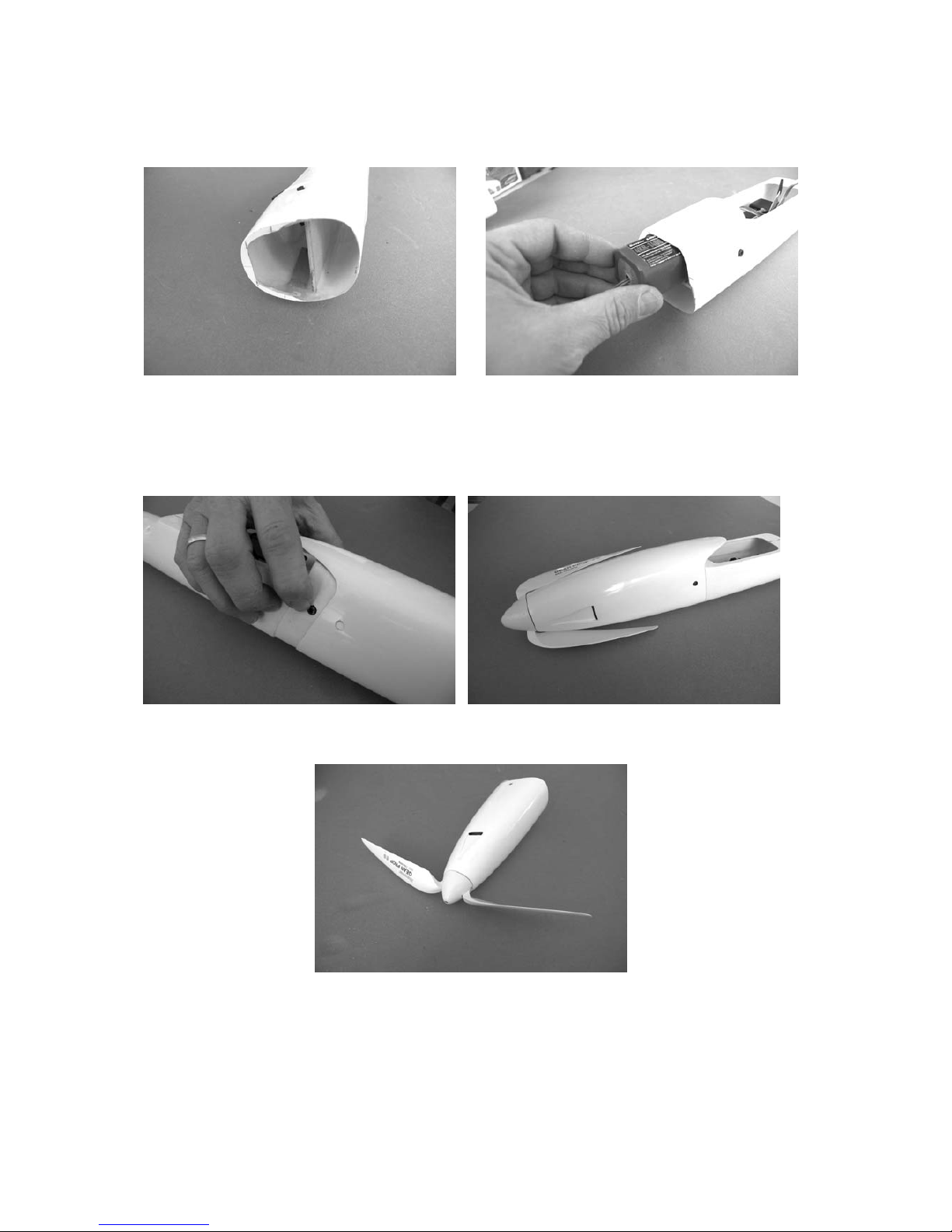
Installing the electric motor
Two holes have to be drilled in the nose bulkhead to suit the motor you intend to install. Cut or file out
the front face of the cooling air intakes as shown in the photo.
Ensure that the cooling slots in the motor line up with the cooling air intakes in the fuselage nose. If
you are fitting a geared motor a sub-former should be installed under the motor itself. You may need
to trim the former to follow the inside shape of the fuselage accurately.
When installing a geared motor the 3 mm thick circular former must be fitted between motor and nose
bulkhead, otherwise the distance between fuselage nose and spinner backplate will be excessive.
The attachment of the push-fit nose cone requires two 5.6 mm Ø holes to be drilled through the nose
cone and the fuselage on both sides. The position of the holes is shown in the photograph; mark these
locations on the nose cone.
approx. 50 mm
approx. 12 mm
approx. 5.6 mm Ø
The retaining plates can now be glued in place; each consists of a strip of plywood and an M3 x 6
socket-head cap screw.
approx. 6 mm
2.4 mm Ø hole
Drill a hole in the two plywood strips for the M3 x 6 socket-head cap screws, positioned as shown in
the photo.
The plywood strips can now be glued in the fuselage, with the screw heads engaging centrally in the
5.6 mm Ø holes. They should not foul the edge of the holes.
The ply strips have to act as springs, and therefore they must not be glued over their full length
otherwise the spring effect will be lost. It is sufficient to fix them over a length of about 10 - 15 mm.
Open up the front of the nose cone so that the receiver battery can be slid into place. Slight pressure
on both screw heads releases the latches, and the nose cone can then be withdrawn and later refitted.
Assemble the folding propeller following the instructions supplied with the set.
The final work on the fuselage is to drill the holes for the wing locating dowel and the retaining screw.
This is the procedure: drill a central 4 mm Ø hole in the fuselage for the locating dowel as shown in
the photo. The position can be seen in the picture; you may need to finish it off with a small round file.
The hole for the wing retainer screw should be drilled using the wing centre section as a template.
The nut for the wing retainer screw can now be glued in the fuselage.
The nut must be fitted in a piece of triangular balsa strip to allow for the taper of the wing section. Use
UHU plus for this joint.
Ensure that the narrow end of the triangular strip faces forward; note that you will have to trim this strip
slightly to obtain a close-fitting joint with the fuselage. Fit a screw from the top to draw the nut and the
strip upwards into proper contact with the fuselage. Important: don’t allow any glue to get onto the
threaded part of the nut or screw.
Fit a 4 mm Ø hardwood dowel in the hole in the leading edge of the wing centre section. Place the
wing centre section on the fuselage and engage the dowel in the locating hole. Set the wing centre
section at right-angles to the fuselage centreline. When you are confident of this, fit a drill through the
hole in the wing and continue the hole into the fuselage, taking care to hold the drill at right-angles to
the top surface of the wing. Here again a 4 mm Ø drill is required.
Installing the ON/OFF switch and charge socket
Install the ON/OFF switch and the charge socket in the fuselage side after filing out suitable
rectangular openings.
The wing
Page 35

Work on the wing is limited to attaching the camber-changing flap and ailerons and installing the
servos.
The first step is to hinge the flap and ailerons to the wings using the procedure already described for
the elevators.
The flap must be able to deflect down and up when actuated by the servo. To cater for this movement
the flap leading edge is tapered asymmetrically, i.e. a cross-section of the flap leading edge exhibits a
right-angle at one edge. The flap must be attached to the wing with the right-angled edge at the top.
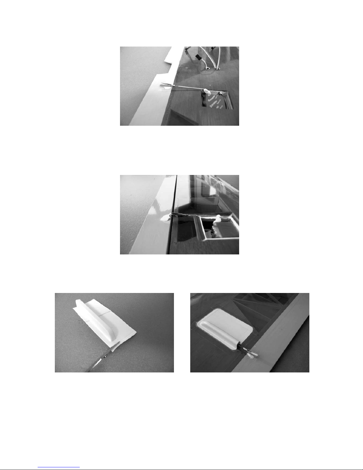
The camber-changing flap servo can now be installed.
First cut away the covering film from the wing centre section over the flap servo well. We recommend
that you cut 4 or 5 mm inside the line, then iron the projecting film down and onto the ribs and spar.
Fit the servo in a heat-shrink sleeve and shrink the sleeve round the servo.
The advantage of this method of servo mounting is that the servo can easily be removed for repair or
maintenance: all you do is slit the heat-shrink sleeve and lift the servo out.
The servo should be glued into the wing centre section with the output shaft parallel to the wing trailing
edge as shown in the photo. Locate the linkage hole in the servo output arm which is 13 mm from
centre and drill out this hole to 2 mm Ø.
Route the servo lead out of the rear hole in the bottom wing skin.
Two extension leads have to be fitted in the wing centre section for connecting the two aileron servos
(Order No. 3935.65). Remove the plastic connector housings carefully using a pin: see photo.
Wrap a piece of tape round the bare contact ends; the extension lead can now be slipped into the
plastic sleeve working from the outboard rib, or pulled through using a length of 0.8 mm Ø steel wire.
Fit the plastic housing back onto the contacts. Important: make sure they are in the right order!
approx. 8 mm
Drill a 3 mm Ø hole in the camber-changing flap exactly in line with the servo output arm, as shown in
the photos.
Cut down the horn spigot to suit the thickness of the flap. Drill out the outermost hole to 1.6 mm Ø and
glue it in the flap as shown in the photo. Remove the covering film over the area where the horn is to
be fitted.
The flap linkage consists of an M2 clevis and an M2 threaded pushrod. Screw the clevis onto the
threaded rod as far as it will go, and connect it to the horn. You can now mark the correct length of the
pushrod. Note that the servo output arm should not be at the normal 90° position, but offset to the rear
(towards the trailing edge) on the output shaft by two splines. Switch on the RC system briefly to
check this. Form a Z-bend in the pushrod at the marked point, preferably using Z-bend pliers, e.g.
Order No. 5732.
Before flying the model the control surface travels must be set up as stated on the last page of these
instructions.
The servo well cover can now be trimmed to size and glued over the servo recess.
The cover can either be glued in place using UHU Alleskleber Kraft or similar, or attached using strips
of tape as shown in the photo.
The next stage is to install the two aileron servos.
Wrap the servos in heat-shrink sleeves as described for the flap servo. Set the servos to neutral from
the transmitter and screw the output arms on them. Install the servos in the outboard wing panels as
shown in the photo.
Drill 3 mm Ø holes for the horns in the ailerons about 9 mm aft of the hinge pivot line. Cut down the
horn spigot to the thickness of the aileron, remove the covering film from the aileron over the horn joint
area, and glue the horns in place.
Assemble the linkages exactly as described for the camber-changing flap. When the servos are at
centre both ailerons should also be at centre / neutral.
Trim the servo well covers to final size and attach them to the wings as already described.
The final step is to apply the decals to the model. Cut out the individual decals as accurately as you
can using a pair of scissors.
Page 36

The canopy decals are positioned as follows: lay the decals on the nose cone without removing the
backing film, position them carefully and mark a few reference points on the nose cone surface. The
canopy decals are best applied starting from the underside and working towards the centre. Minor
discrepancies at the centre joint line can easily be corrected using a sharp balsa knife.
Installing the towhook
If you intend to fly your CUMULUS XXL as a pure glider, you can launch it at a flat field site using a
bungee or winch system. In this case you will need to install a plastic towhook in the bottom of the
fuselage.
Drill two 3 mm Ø holes in the underside of the fuselage for the towhook.
The position of the holes is shown in the photo. The 47 mm dimension is the point at which the towring
will engage with the towhook.
Important: the hook should only be fitted if your CUMULUS XXL is to be used as a pure glider, as it
prevents the electric motor flight battery being installed.
approx. 47 mm
Assembling the CUMULUS XXL
Attach the V-tail assembly to the fuselage using the two countersunk screws provided.
Deflect the elevators down and connect the hooks on the linkage cables to the elevator horns.
Connect the wing-mounted servo leads to the receiver, then engage the wing centre section locating
dowel in the hole in the fuselage and secure the wing by fitting the plastic countersunk screw and
spreader plate.
Connect the two outboard wing panels to the centre section using the pre-formed steel rods,
connecting the aileron servo leads to the extension leads in the wing centre section at the same time.
Apply strips of tape over the top and bottom of the wing joints to prevent the outboard panels coming
loose.
Balancing the CUMULUS XXL
Assemble the model completely, ready to fly, and support it under both wing roots at a point about 80 86 mm aft of the leading edge. The model should now balance level, ideally with the nose inclined
slightly down. Re-position the flight battery if necessary until this is the case. Once you have
established the correct battery position glue a block of balsa in the fuselage to act as a locating piece.
For initial test-flights the CG should be at the forward end of the stated range.
Before every flight check that all control surfaces are exactly at centre (neutral) when the transmitter
sticks and trims are also at centre.
Control surface travels
Ailerons 22 mm up 8 mm down
Elevators 15 mm up 12 mm down
Rudder 15 mm right 15 mm left
Flap 3 mm down 1.5 mm up
Butterfly (Crow) setting
Ailerons up 28 mm
Flap down 35 mm
Elevators down 5.5 mm
Important:
When installing and adjusting the mechanical linkages it is vital to ensure that they all work smoothly
and are able to carry out their full travel - including trim movement - without fouling at any point, and
without being obstructed mechanically (servos stalled).
When you move the rudder stick to the right, the right elevator should move down and the left elevator
up. Pull the elevator stick back towards you, and both elevators should move up through the same
angle (forward stick = down). If you move the aileron stick to the right, the right-hand aileron should
rise, the left-hand aileron fall. Pull the Butterfly stick back towards you, and the ailerons should rise
and the flap fall. We recommend assigning the camber-changing flap to a slider on the transmitter; it is
best to limit the flap’s travel electronically, so that the stated deflections are obtained at full travel of
the slider.
And now all that remains is to wish you many hours of pleasure building and flying your CUMULUS
XXL.
Page 37

Yours - the Graupner team!
GRAUPNER GmbH & Co. KG D-73230 KIRCHHEIM/TECK GERMANY
We reserve the right to introduce modifications. No liability for printing errors. Ident No. 46413 04/2003
Made in the Czech Republic
Page 38

pour Réf. N°4546
CUMULUS XXL
Instructions de montage
Pour propulsion électrique alimentée par 8 éléments
Un ensemble R/C à 5 voies est nécessaire
Avant-propos:
Grâce à son haut degré de préfabrication, ce modèle pourra être mis rapidement en ordre de vol
même par un débutant.
Les vitesses en vol motorisé aussi bien qu'en vol plané sont optimalement adaptées entre-elles, c'està-dire que la différence de vitesse est à peine remarquable, ce qui est une facilité essentielle pour un
débutant.
Par sa faible charge alaire et sa vitesse de vol, le CUMULUS XXL ne pourra évoluer par vent fort
qu'après quelques heures de vol d'entraînement par temps calme.
Le CUMULUS XXL n'est pas adapté pour la voltige, mais avec des ordres bien dosés un looping ou
un renversement pourront néanmoins être effectués.
Le CUMULUS XXL répond très bien aux ascendances thermiques et peut parfaitement spiraler. S'il
arrive qu'il montre à une trop haute altitude, par ex. sous l'influence d'une forte ascendance, un
dégagement sûr est possible avec les ailerons et le volet de courbure braqués en position Butterfly.
Attention: Ce modèle n'est pas un jouet!
Si vous n'avez encore aucune expérience avec un tel modèle motorisé, faites-vous assister par un
modéliste expérimenté. Si ce modèle est utilisé sans connaissances préalables, il peut causer des
blessures. Pensez à votre sécurité et à votre santé.
Important! A lire avant de commencer la construction!
Même si vous avez déjà construit de nombreux modèles R/C, veuillez lire attentivement ces
instructions et vérifier si les pièces contenues dans cette boite de construction sont complètes.
Beaucoup d'efforts ont été faits pour rendre les assemblages les plus simples possible, sans pour
autant nuire à la sécurité.
Conseils pour le film de recouvrement
En raison des fortes variations climatiques (Température, humidité, etc…) le recouvrement en film
plastique peut présenter des petits plis. Ceci est du à la nature de la construction en bois avec ce
genre de recouvrement. Il pourra être retendu à l'aide d'un séchoir électrique comme ceux utilisés en
modélisme, en procédant comme suit:
Plis: Chauffer le film et le frotter avec un chiffon doux.
Aile déformée: Tordre légèrement l'aile dans le sens contraire à la déformation pour détendre le
recouvrement et le retendre en appliquant l'air chaud.
Précaution! Ne pas appliquer plus de chaleur que nécessaire. Un fer à repasser trop chaud fera
fondre le film et il en résultera un trou!
Ce modèle largement préfabriqué ne nécessite encore que peu de temps pour sa finition. Mais les
travaux restants sont importants et devront être effectués avec soin. De leur parfaite exécution
dépendront la solidité finale prévue pour le modèle et ses performances de vol; c'est pourquoi il
conviendra de travailler avec patience et précision!
Page 39

Conseils pour l'utilisation du CUMULUS XXL
Avant de commencer la construction, la totalité des instructions de montage et d'utilisation
devra être attentivement lue. Vous êtes seul responsable de la sécurité d'utilisation de votre
modèle R/C.
Il est conseillé aux jeunes modélistes de se faire assister pour la construction et les premiers
vols par un adulte déjà familiarisé avec les particularités et les possibilités de danger
représentés par un modèle volant radiocommandé.
Ces instructions d'utilisation devront être soigneusement conservées et remise à l'utilisateur
suivant en cas de vente du modèle.
Demandez à votre revendeur les mesures de sécurité à prendre pour l'utilisation des modèles
volants R/C, il vous renseignera volontiers.
Les modèles volants radiocommandés sont des appareils qui peuvent être dangereux et qui
exigent de leur utilisateur une haute compétence et la conscience de sa responsabilité.
Un modèle réduit volant est comparable à un véritable aéronef pour lequel toutes les
dispositions légales doivent être prises; la possession d'une assurance est obligatoire.
Il conviendra d'utiliser exclusivement les éléments fournis dans la boite de construction ainsi
que les accessoires d'origine Graupner et les pièces détachées conseillées. Si un seul
composant de la propulsion est remplacé, une parfaite sécurité de fonctionnement ne pourra
plus être assurée et le bénéfice de la garantie sera perdu.
Utilisez toujours des connecteurs avec une sécurité contre les inversions de polarité et
adaptés entre-eux.
Tous les conducteurs de courant, les connexions ainsi que la batterie de propulsion de
confection personnelle devront être isolés contre les court-circuits.
Ne combinez jamais des connecteurs différents, par ex. des contacts en tôle avec des contacts
dorés, car une parfaite sécurité de contact n'est plus garantie.
Avec l'utilisation des commutateurs ou des régulateurs assurant l'alimentation de la réception
(BEC), utilisez exclusivement des connecteurs Graupner à contacts dorés.
Evitez les court-circuits et les inversions de polarités.
Par la haute énergie des batteries NC, il existe un danger d'explosion et d'incendie.
Un modèle volant R/C ne peut évoluer correctement que s'il a été construit et réglé
conformément aux instructions de montage et seule une utilisation prudente et responsable
évitera de provoquer des dommages matériels ou corporels. Personne ne peut prétendre
prendre place dans un planeur réel et le piloter sans un apprentissage préalable; il faut aussi
apprendre à piloter un modèle réduit!
Le fabricant n'a cependant aucune possibilité d'influencer la construction et l'utilisation d'un
modèle de sa production. C'est pourquoi nous attirons ici l'attention sur les dangers
représentés en dégageant toute responsabilité.
Faites-vous assister par un modéliste expérimenté, ou inscrivez-vous dans une association ou
dans une école de pilotage. Le mieux est de faire partie d'un club d'aéromodélisme pour
pouvoir voler sur un terrain autorisé.
Les colles et les peintures contiennent des solvants qui dans certaines conditions peuvent être
nocifs pour la santé. Pour cette raison, observez impérativement le mode d'emploi et les
avertissements indiqués par le fabricant correspondant.
L'utilisateur doit être en pleine possession de ses facultés physiques et mentales. Comme
pour la conduite des automobiles, le pilotage des modèles volants sous l'effet de l'alcool ou de
la drogue n'est pas autorisé.
Avant de faire voler votre modèle, informez tous les passants et les spectateurs sur les
dangers qu'il peut présenter et priez-les de se tenir à une distance de sécurité suffisante, à au
moins 5 mètres derrière le champ de rotation de l'hélice.
Tenez-vous à une distance de sécurité suffisante de personnes ou d'objets; ne survolez jamais
de personnes à basse altitude et ne volez jamais dans leur direction.
Page 40

Un modèle volant R/C ne doit voler que par des températures extérieures comprises entre – 5°
à + 35°C. Des températures extrêmes peuvent conduire par ex. à une modification de la
capacité des accus, des propriétés des matériaux et de la résistance des collages.
Chaque modéliste doit se comporter de façon à ce que l'ordre et la sécurité publiques, vis-à-vis
des autres personnes et des biens, ainsi que l'activité des autres modélistes ne soient pas mis
en danger, ni perturbés.
Ne faites jamais voler votre modèle à proximité des lignes à haute tension, dans les zones
industrielles, les agglomérations, sur les voies publiques, les places, dans les cours d'école,
les parcs et les aires de jeux, etc…
Les avertissements donnés devront être impérativement respectés. Leur non-observation peut
conduire à de sérieux dommages et dans les cas extrêmes à des blessures graves.
Les hélices et en général toutes les pièces en rotation entraînées par un moteur présentent un
danger de blessure permanent et ne doivent toucher aucune partie du corps! Une hélice
tournant à haut régime peut par ex. couper un doigt!
Ne vous tenez jamais devant ou sur le côté du champ de rotation d'une hélice! Une pièce peut
toujours se desserrer et être projetée à haute vitesse avec une très forte énergie et vous
blesser ou une tierce personne. Veillez également à ce qu'aucun objet n'entre en contact avec
l'hélice en rotation.
Le risque de blocage d'une hélice par un objet quelconque doit être exclu.
Veillez aux vêtements flottants tels qu'écharpe, manches de chemise, etc.. qui pourraient être
aspirés et s'enrouler autour de l'hélice.
Avant chaque utilisation, contrôlez le modèle et toutes les pièces qui y sont rattachées (par ex.
hélice, réducteur, éléments R/C, etc…) pour vérifier leur fixation et détecter une possible
détérioration. Ce n'est qu'après avoir remédié à tous les défauts éventuels que le modèle sera
en ordre de vol.
Assurez-vous que la fréquence que vous utilisez est libre avant de mettre votre émetteur en
contact! Uns perturbation peut toujours se produire pour une cause inconnue, sans prévenir!
Le modèle devient alors incontrôlable et livré à lui-même! Ne laissez pas votre émetteur sans
surveillance pour éviter une manipulation par un tiers.
Mettez le moteur électrique en contact lorsque personne ne se trouve dans le champ de
rotation de l'hélice. Ne tentez pas d'arrêter une hélice en rotation! Faites tourner le moteur avec
l'hélice montée uniquement lorsqu'il est solidement fixé dans le modèle.
La position du modèle doit être nettement identifiable durant tout le vol pour garantir un
pilotage sûr. Si vous remarquez l'influence d'une perturbation durant le vol, préparez-vous
immédiatement à atterrir pour des raisons de sécurité. Durant le départ et le processus
d'atterrissage, le terrain doit être libre de toute personne et d'obstacle.
Veillez toujours au bon état de charge des accus, car autrement le parfait fonctionnement de
l'ensemble R/C ne peut être garanti.
N'utilisez jamais de batteries échauffées, devenues défectueuses ou détériorées. Observez les
prescriptions d'utilisation du fabricant des batteries.
Faites une vérification complète de l'installation R/C et du modèle ainsi qu'un essai de portée
avant chaque séance de vols.
Avant de mettre l'installation R/C en contact assurez-vous toujours que l'organe de commande
du moteur électrique sur l'émetteur soit sur la position COUPE, mettez alors toujours d'abord
l'émetteur en contact, ensuite la réception pour éviter un démarrage incontrôlé du moteur.
Ensuite, coupez toujours d'abord la réception et après l'émetteur.
Vérifiez que le sens de déplacement des gouvernes correspond à celui des manches de
commande sur l'émetteur:
Page 41

En déplaçant le manche de commande de direction vers la droite, la gouverne droite de
l'empennage en V doit s'abaisser et la gauche doit se relever. En tirant le manche de
commande de profondeur vers l'arrière (à soi), les deux gouvernes doivent se relever.
Ne donnez aucun déplacement brutal aux manches de commande en vol.
Retirez toutes les batteries du modèle après son utilisation et conservez-les à l'état déchargé
(env. 0,9 V par élément) sous une température comprise entre + 5° à + 25° et hors de la portée
des enfants.
Ces conseils mettent en évidence la diversité des dangers pouvant résulter d'une manipulation
incorrecte et irresponsable. Leur observation permettra de pratiquer en toute sécurité ce loisir
créatif et éducatif que représente l'aéromodélisme.
Conseils pour le vol
Ne faites pas voler votre CUMULUS XXL dans une nature protégée. Prenez en considération les lieux
où vives les animaux et les plantes.
Les arbres et les buissons servent de nid et d'habitat aux oiseaux.
Les batteries usagées ne devront pas être jetées dans une poubelle domestique, mais dans un
container spécialement réservé à cet usage.
Outillage nécessaire pour les assemblages du CUMULUS XXL
Un crayon à mine dure, un rapporteur, un réglet métallique, des ciseaux, un couteau à balsa, par ex.
Réf. N°986, une petite perceuse avec un jeu de forets, un tournevis cruciforme, par ex. N°810, une clé
Allen N°10, du freine-filet, Réf. N°952, les pinces plates et des pinces à ressort, Réf. N°542.1.
Collage des matières
Le tableau ci-dessous donne quelques exemples pour le collage des matières, sans pour autant être
complet:
Matière Exemple de collage Colle à employer
Contre-plaqué avec Platine de servo avec UHU plus endfest 300
fibre de verre fuselage en fibre de verre Réf. N°950.15
Plastique avec balsa Guignol de gouverne avec UHU hart
volet de courbure Réf. N°534.10
Plastique avec plastique Gaine thermo-rétractable avec UHU Colle-seconde
recouvrement de servo Réf. N°1098
Remarque:
Dépolir les emplacements de collage dans le fuselage avec du papier abrasif fin et les nettoyer avec
un solvant neutre pour retirer la poussière. Dans chaque cas, la surface brillante devra être rendue
matte, care autrement un collage résistant avec le fuselage ne pourra être garanti.
Important: Utiliser la colle avec parcimonie pour tous les travaux de collage pour économiser du
poids.
Pour le collage des pièces entre-elles, se référer au mode d'emploi figurant sur le conditionnement
des colles. D'autres qualités de colles se trouvent dans le catalogue général FS.
Equipement R/C pour le CUMULUS XXL
Nous recommandons l'équipement minimum suivant:
Pour la version motoplaneur électrique:
1 Ensemble R/C mc-12 dans la bande des 41 MHz, par ex. Réf. N°4725.41
1 Module de commutation 2 canaux Réf. N°4171
5 Mini-servos ECO C 341 Réf. N°4093
1 Récepteur miniature C 12 Réf. N°3175
1 Batterie d'émission VARTA 8/600 RX Réf. N°3408
1 Accu de réception SANYO 4KR-1400 AE Réf. N°2523
3 Cordons de rallonge Réf. N°3935.11
2 Cordons de rallonge Réf. N°3935.65
1 Noyau en ferrite Réf. N°98516
Page 42

Pour la version planeur:
1 Ensemble R/C mc-12 dans la bande des 41 MHz, par ex. Réf. N°4725.41
5 Mini-servos ECO C 341 Réf. N°4093
1 Accu de réception SANYO 4N-800 RX Réf. N°3454
1 Batterie d'émission VARTA 8/600 RX Réf. N°3408
3 Cordons de rallonge Réf. N°3935.11
2 Cordons de rallonge Réf. N°3935.65
1 Noyau en ferrite Réf. N°98516
Pour des raison de sécurité, il est vivement recommandé d'utiliser des batteries rechargeables pour
l'alimentation de l'émetteur et de la réception.
Pour le chargeur correspondant, voir dans le catalogue général FS.
Propulsion électrique et accessoires
Propulsion
Réf. N°
Condensateur
antiparasite
Réf. N°
Hélice à pales repliables
Réf. N°
Batterie de propulsion
Réf. N°
Régulateur e vitesse
ou Commutateur
Réf. N°
SPEED 600
ECO 7,2 V
3323
3588
CAM FOLDING PROP
23x12 cm
1335.23.12
ECO POWER
9,6 V/1,5 Ah
2497
ou:
ECO POWER
9,6 V/2,1 Ah
2483
SOFT Switch 18
2866
ou:
POWER V 18
2859
SPEED GEAR
600 PLUS
8,4 V
6326
non
nécessaire
SAM GEAR PROP
30x25 cm
1311.30.25
SANYO 9,6 V/2,3 Ah
2474
ou:
GMVIS 9,6 V/3,3 Ah
2474.S8
ou:
ECO-POWER
9,6 V/2,1 Ah
2483
Incorporé au moteur
Le fil rouge devra être déconnecté de la prise sur le cordon de raccordement au récepteur du
régulateur. Soulever avec précaution la languette en plastique à l'aide d'une épingle, tirer sur le fil et
l'isoler comme représenté sur les photos.
Fonctions R/C Servos conseillés
Type Réf. N° Qté
Direction C 341 4083 2
Profondeur C 341 4083 2
Ailerons C 341 4083 2
Volets de courbure C 341 4083 1
Commutateur moteur pour la version électrique.
Caractéristiques techniques Version électrique Version planeur
Envergure, env. 2250mm 2250mm
Longueur du fuselage, env. 1045mm 1045mm
Longueur hors-tout, env. 1085mm 1085mm
Profil de l'aile GQ/W 10% GQ/W 10%
Surface de l'aile, env. 42,1 dm² 42,1 dm²
Surface du stabilisateur, env. 7,8 dm² 7,8 dm²
Surface totale, env. 49,9 dm² 49,9 dm²
Poids en ordre de vol, env. 1640 g. 1090 g.
Instructions de montage
Avant l'exécution des travaux de collage, veillez à ce que les surfaces soient sèches et exemptes de
traces de gras et de poussière.
Page 43

Fuselage avec l'empennage pour la version électrique
La première opération consistera à monter les servos pour l'empennage en V sur la platine.
Pour cela, le palonnier des servos devra être modifié comme représenté sur les photos suivantes.
Fixer les palonniers ainsi préparés sur l'axe de sortie des servos préalablement mis en position
neutre.
Le trou extérieur sur les palonniers devra être repercé à φ 2mm pour le montage d'un raccord de
tringlerie. Monter chaque raccord avec un écrou nylstop M2 de façon à ce qu'il puisse pivoter
librement sans jeu notable.
Placer les servos avec les supports (Voir la photo) sur la platine et reporter les trous de fixation sur
celle-ci.
Percer des avant-trous de φ 1,5mm et fixer les supports des servos sur la platine avec les vis parker à
tête cylindrique fournies; limer la partie dépassante des vis à ras sous la platine, car autrement la
batterie de propulsion serait détériorée.
La platine des servos ainsi préparée sera collée dans le fuselage de façon à ce que la batterie de
propulsion puisse être glissée en dessous; les surfaces de collage dans le fuselage devront être
préalablement bien dépolies.
Important: Vérifier absolument la distance entre la platine des servos et le fond du fuselage.
Après la prise de la colle, les deux servos pourront être placés dans les supports et fixés avec des
rondelles plates et des vis parker φ 2,2x6,5mm.
L'empennage en V
Monter d'abord les deux gouvernes sur les plans fixes correspondants avec du ruban adhésif.
Coller d'abord une bande de ruban adhésif sur le dessus et sur toute la longueur des plans fixes.
Coller ensuite les gouvernes par le dessous sur la face adhésive du ruban. Basculer maintenant les
gouverne de façon à ce que leur dessus repose sur le plan fixe. Dans cette position, coller de même
une bande de ruban adhésif centrée sur l'articulation, comme représenté sur les photos suivantes.
Maintenant que les gouvernes sont montées, les deux plans de l'empennage en V pourront être collés
ensemble. Il est important de respecter ici l'angle d'ouverture des deux plans qui doit être d'environ
110°; ceci pourra être contrôlé avec un rapporteur.
Maintenir les deux plans assemblés jusqu'à la prise de la colle, par ex. avec des pinces à ressort, Réf.
N°542.1.
Coller ensuite le renfort en contre-plaqué sous l'assise de l'empennage dans le fuselage et le
maintenir jusqu'à la prise de la colle avec des pinces à ressort.
Coller ensuite le renfort triangulaire sur le dessus de l'empennage. Pour cela, le film de recouvrement
devra être retiré sur la surface de collage correspondante; tracer les limites de celle-ci avec un crayon
feutre et découper le film sur une surface un peu plus faible pour mettre le bois à nu. Coller en place
le renfort triangulaire et le fixer avec des épingles jusqu'à la prise de la colle.
L'empennage pourra être collé à demeure sur le fuselage, ou fixé par des vis, ce qui est préférable
pour le transport.
Procéder comme suit pour rendre l'empennage démontable:
Fixer le renfort en contre-plaqué (qui sera collé sous l'assise de l'empennage dans le fuselage)
exactement en position sous l'empennage avec deux bandes de ruban adhésif.. Les trous pour les
deux vis de fixation pourront maintenant être percés par le haut. Pour être sûr que l'empennage ne
tourne pas sur le renfort, introduire une vis de fixation dans le premier perçage et pratiquer ensuite le
second.
Retirer maintenant la planchette de renfort et coller deux écrous spéciaux dans celle-ci.
Après la prise de la colle, coller la planchette de renfort dans le fuselage; une petite rectification sur
les bords droit et gauche pourra être éventuellement nécessaire. Maintenir la planchette en place
avec les deux vis de fixation jusqu'à la prise de la colle. Important: veiller à ce que de la colle ne
coule pas sur le filetage des vis.
Le prochain travail consistera à confectionner les ressorts de torsion pour les gouvernes.
Page 44

Sur le CUMULUS XXL, la profondeur est actionnée par des câbles; c'est-à-dire que lorsque ceux-ci
sont tirés, les gouvernes sont braquées en piqué, le braquage en cabré est obtenu au moyen des
ressorts de torsion.
Les ressorts de torsion devront être façonnés conformément au dessin (deux symétriquement
opposés).
Les deux extrémités des ressorts de torsion seront introduites l'une dans le plan fixe, l'autre dans la
gouverne et les ressorts seront comprimés en les tournant sur 90° de façon à ce que les gouvernes
soient braquées en cabré. Une petite rainure devra être pratiquée dans les plans fixes pour les
ressorts afin que les gouvernes puissent aussi se braquer totalement en piqué.
Les deux guignols pourront maintenant être montés sur les gouvernes en veillant à ce qu'ils aient un
écart entre-eux d'environ 12mm (Voir la photo) et que le point de connexion corresponde au point
d'articulation de la gouverne. Les guignols devront être modifiés conformément à la photo.
Couper la partie dépassante des vis de fixation et les limer au ras des contre-plaques.
Les câbles seront attachés sur les guignols par des crochets. Nouer les câbles sur les crochets et
bloquer le nœud avec une goutte de colle-seconde.
Afin que les câbles ne puissent pas frotter dans le fuselage, des gaines en plastique
(φ 3,2x2,2x100mm) seront collés dans le fuselage sous l'empennage et derrière le bord de fuite de
l'aile; les gaines seront enfilées sur les câbles avant de les attacher.
Introduire maintenant les câbles par l'arrière dans le fuselage; les extrémités avant seront introduites
dans le perçage transversal des raccords de tringlerie. Pour régler la profondeur, les servos devront
être en position neutre en mettant provisoirement l'installation R/C en contact; veiller à ce que les
trims soient en position milieu sur l'émetteur. Connecter maintenant les crochets sur le trou extérieur
des guignols. Pour fixer les câbles dans les raccords de tringlerie, des petits tubes en aluminium
(φ 2x1,6x15mm) seront enfilés sur leur extrémité et bloqués par la vis pointeau.
La tête de fuselage
Le CUMULUS XXL pourra être réalisé en deux versions:
1. En version planeur pur
2. En version motoplaneur électrique
La tête du fuselage enfichable pourra être échangée sur le terrain de vol en très peu de temps et sans
outil.
Montage du moteur électrique
Deux trous seront percés dans le couple avant selon le moteur utilisé. Découper la face avant des
entrées d'air sur les côtés du fuselage et les rectifier à la lime, comme montré sur la photo. Pour le
montage d'un réducteur, un couple auxiliaire sera collé sous le moteur et éventuellement ajusté au
contour intérieur du fuselage.
Pour la fixation du moteur à réducteur, le couple rond de 3mm d'épaisseur devra être interposé entre
le moteur et le couple avant, car autrement l'écart entre la tête de fuselage et l'embase du cône
d'hélice serait trop grand.
Pour la fixation de la tête enfichable, un trou de φ 5,6mm devra être percé au travers de celle-ci et du
fuselage; relever les cotes sur la photo et les reporter sur la tête de fuselage.
Les planchettes de verrouillage composées chacune d'une bande de contre-plaqué et d'une vis BTR
M3x6 seront maintenant collées en place.
Percer le trou pour la vis BTR M3x6 dans les bandes de contre-plaqué conformément aux cotes à
relever sur la photo.
Les deux bandes de contre-plaqué seront collées dans le fuselage de façon à ce que la tête des vis
puisse pénétrer sans frotter dans les perçages.
Pour cela, veiller à ce que les bandes de contre-plaqué ne soient pas collées sur toute leur longueur;
un collage sur une longueur de 10-15mm est suffisant car les bandes de contre-plaqué doivent faire
office de ressort.
L'avant du fuselage devra être découpé en correspondance pour pouvoir y introduire l'accu de
réception.
Page 45

Par une simple pression sur la tête des deux vis, la tête de fuselage sera déverrouillée et pourra être
retirée et remise en place.
Monter l'hélice à pales repliables conformément aux instructions fournies avec celle-ci.
Les derniers travaux à effectuer sur le fuselage sont le perçage des trous pour le tourillon d'arrêt et
pour les vis de fixation de l'aile.
Procéder comme suit: Percer un trou de φ 4mm au milieu du fuselage pour le tourillon d'arrêt; sa
position est visible sur la photo, le rectifier éventuellement avec une petite lime ronde.
Percer ensuite le trou dans le fuselage pour la vis de fixation à l'aide de l'aile:
En raison de la forme du profil de l'aile, l'écrou spécial devra être collé dans le fuselage en interposant
une pièce de baguette triangulaire.
Veiller à ce que le bord mince de la baguette triangulaire soit orienté vers l'avant; une petite
rectification peut être éventuellement nécessaire afin qu'elle puisse être collée bien à plat. La baguette
triangulaire pourra maintenant être collée dans le fuselage (UHU plus).
Percer un trou de φ 4mm dans le bord d'attaque de la partie centrale de l'aile et y introduire le tourillon
d'arrêt. Placer la partie centrale de l'aile sur le fuselage de façon à ce que d'une part le tourillon
s'engage dans le perçage et que d'autre part l'aile forme un angle droit avec l'axe longitudinal du
fuselage. Lorsque ceci est assuré, le perçage dans l'aile pour la vis de fixation pourra être reporté sur
le fuselage avec une perceuse; pratiquer ce perçage également avec un foret de φ 4mm en l'alignant
perpendiculairement à l'extrados de l'aile.
L'écrou spécial pourra maintenant être collé dans la baguette triangulaire; le maintenir serré avec la
vis jusqu'à la prise de la colle. Important: Veiller à ce que la colle ne coule pas sur le filetage de la
vis.
Montage de l'interrupteur et de la prise de charge
Monter l'interrupteur et la prise de charge sur le flanc du fuselage après avoir pratiqué les ouvertures
nécessaires, comme représenté sur la photo.
L'aile
Les travaux sur l'aile sont limités à la pose des volets d'ailerons et de courbure ainsi qu'au montage
des servos.
Monter d'abord les volets d'aileron et de courbure comme il a déjà été décrit pour les gouvernes de
l'empennage.
Pour le volet de courbure, il faudra veiller à ce qu'il puisse se braquer ultérieurement aussi bien vers le
haut que vers le bas. Pour cela, le bord d'attaque du volet est asymétrique; c'est-à-dire que vu en
coupe, il forme un angle droit. Le volets devra être monté sur l'aile de façon à ce que cet angle droit se
trouve sur le dessus.
Le travail suivant consistera à monter le servo du volet de courbure.
Découper le film de recouvrement sur le logement du sevo dans la partie centrale de l'aile; le mieux
est de laisser subsister une bordure de 4-5mm de largeur sur le pourtour, puis de la rabattre vers
l'intérieur et de la coller au fer contre les nervures et le longeron.
Enrober le servo de gaine thermo-rétractable pour le coller.
Ceci présente l'avantage de pouvoir retirer facilement le servo en cas d'une nécessité de réparation,
en découpant simplement la gaine thermo-rétractable.
Le servo sera collé dans son logement parallèlement au bord de fuite de l'aile; voir la photo. Repercer
à φ 2mm le trou de connexion sur le palonnier avec un bras de levier de 13mm.
Faire sortir le cordon du servo au travers du perçage arrière dans le coffrage inférieur.
Un cordon de rallonge (Réf. N°3935.65) pour le raccordement des deux servos d'ailerons devra être
introduit à droite et à gauche dans la partie centrale de l'aile. Pour cela, les contacts des fils du cordon
devront être déconnectés de la prise en soulevant les lamelles en plastique avec précaution à l'aide
d'une épingle; voir la photo.
Isoler les contact mis à nu avec un morceau de ruban adhésif.
Les cordons de rallonge sortant des nervures de fermeture pourront maintenant être introduit dans les
tubes en plastique, ou au moyen d'une corde à piano de φ 0,8mm.
Reconnecter ensuite les contacts des fils dans la prise des cordons. Important: Veiller au respect des
polarités!
Page 46

Percer un trou de φ 3mm dans le volet de courbure, dans l'alignement du palonnier du servo, comme
représenté sur les photos.
Raccourcir la cheville du guignol en correspondance de l'épaisseur du volet. Repercer le trou extérieur
du guignol à φ 1,6mm et le coller dans le perçage du volet, comme montré sur la photo; pour cela,
retirer le film de recouvrement sur le volet en correspondance de la surfa ce d e collage.
La tringlerie est composée d'une chape M2 et d'une tringlerie filetée M2.
Visser totalement la chape sur le filetage de la tringlerie et la connecter sur le guignol; sa longueur
exacte pourra maintenant être marquée. Décaler le palonnier du servo sur deux cannelures de l'axe
de sortie, vers le bord de fuite de l'aile; pour cela, mettre l'installation R/C provisoirement en contact.
Pour connecter la tringlerie sur le palonnier du servo, contre-couder son extrémité avec des pinces,
par ex. Réf. N°5732.
Le prochain travail consistera au collage des deux sevos d'ailerons dans leur logement les enrobant
de gaine thermo-rétractable, comme il a été décrit pour celui du volet de courbure.
Percer un trou de φ 3mm dans les volets d'ailerons, dans l'alignement du palonnier du servo, à environ
9mm derrière l'axe d'articulation. Raccourcir la cheville des guignols en correspondance de l'épaisseur
des volets d'ailerons, retirer le film de recouvrement sur les volets en correspondance de la surfac e de
collage et coller les guignols.
Confectionner les tringleries d'ailerons comme il a été indiqué pour celle du volet de courbure. Les
deux volets d'ailerons doivent se trouver en position milieu avec les servos au neutre.
Les recouvrements de servo pourront maintenant être ajustés et collés en place soit avec de la colle,
par ex. UHU Alleskleber, ou avec des bandes adhésives, comme représenté su r la photo.
L'ensemble R/C sera ultérieurement réglé pour le vol en correspondance des débattements de
gouverne indiqués
Le travail final sur le modèle consistera à la pose des motifs de décoration. Découper les différents
motifs avec des ciseaux en suivant au plus près leur contour.
Procéder comme suit pour poser le motif représentant la verrière de cabine; poser le motif sur la tête
de fuselage, sans retirer la feuille de protection et tracer son contour avec un crayon. Le collage
commencera de préférence par le milieu; de petites différences sur les bords pourront être égalisées
avec la lame bien tranchante d'un couteau à balsa.
Montage du crochet de treuillage
Si le CUMULUS XXL est réalisé en version planeur pur, il pourra être monté en altitude avec un treuil.
Pour cela, un crochet de treuillage en plastique sera fixé sous le fuselage.
Percer deux trous de φ 3mm dans le fond du fuselage pour fixer le crochet.
La cote est à relever sur la photo; la distance de 47mm indique le point où sera accroché l'anneau du
fil de treuillage.
Important: Le crochet de treuillage sera monté uniquement si le CUMULUS XXL est utilisé en planeur
pur, car la batterie de propulsion pour le moteur électrique ne pourra plus être mise en place.
Assemblage du CUMULUS XXL
Fixer l'empennage en V sur le fuselage avec les deux vis à tête fraisée. Braquer les gouvernes vers le
bas et connecter le crochet des câbles de commande sur les guignols. Connecter le cordon des
servos sur le récepteur. Introduire le tourillon d'arrêt de la partie centrale de l'aile dans le perçage du
fuselage et fixer l'aile sur le fuselage avec la vis à tête fraisée et la plaquette d'appui.
Monter les deux panneaux d'aile extérieurs avec les broches en acier en forme de V à droite et à
gauche de la partie centrale. Fixer les deux panneaux extérieurs sur cette dernière avec du ruban
adhésif collé sur l'extrados et l'intrados.
Centrage du CUMULUS XXL
Soutenir le modèle entièrement équipé et en ordre de vol sous l'aile, sur un point situé à environ 80–
86mm derrière le bord d'attaque, de chaque côté du fuselage; il doit se tenir en équilibre sur ce point,
avec le nez du fuselage penchant légèrement vers le bas. Ceci pourra être obtenu par le déplacement
de la batterie de propulsion; avec la bonne position de celle-ci, une butée sera collée dans le fuselage
(Découpe de balsa).
Pour les premiers vols, le centrage devra être situé sur le point avant indiqué (80mm).
Avant le premier vol, toutes les gouvernes devront être mises exactement en position milieu (position
neutre) avec les trims sur l'émetteur.
Page 47

Débattements des gouvernes:
Ailerons plus 22mm, moins 8mm
Profondeur plus 15mm, moins 12mm
Direction plus 15mm, moins 12mm
Volet de courbure plus vers le bas 3mm, moins vers le haut 1,5mm
Position Butterfly:
Ailerons vers le haut 28mm
Volet de courbure vers le bas 35mm
Profondeur vers le bas 5,5mm
Important:
Lors du montage des tringleries, veiller à ce qu'elles puissent se mouvoir librement et que le servo
correspondant puisse se déplacer sur la totalité de sa course, incluant le trim, sans être bloqué
mécaniquement.
En déplaçant le manche de commande de direction vers la droite, la gouverne de droite de
l'empennage en V doit s'abaisser et la gauche se relever. En tirant le manche de commande de
profondeur vers l'arrière (à soi), les deux gouvernes doivent se relever (et en le poussant en avant,,
s'abaisser). En déplaçant le manche de commande des ailerons vers la droite, le volet droit doit se
soulever et le gauche s'abaisser. En tirant le manche de commande Butterfly vers l'arrière (à soi), les
deux volets d'ailerons doivent se relever et le volet de courbure s'abaisser. Le volet de courbure sera
commandé de préférence par un curseur linéaire dont la course totale sera limitée électroniquement
pour obtenir les débattements indiqués.
Il nous reste à vous souhaiter beaucoup de plaisir avec les vols de votre CUMULUS XXL!..
GRAUPNER GmbH & Co. KG D-73230 KIRCHHEIM/TECK GERMANY
Sous réserve de modifications! Nous ne sommes pas responsables d'éventuelles erreurs d'impression! 04/2003
Made in Tschechien
 Loading...