

GRAUPNER CLUB STAR II Instructions Manual
Order No. 4547
4548
INSTRUCTIONS
CLUB STAR II
Glider and
Electric
For electric power system and 2 or 3 LiPo cells
This model requires a four-function radio control system
GRAUPNER GmbH & Co. KG D-73230 KIRCHHEIM/TECK GERMANY
Modifications reserved. No liability for printing errors Id. No. 0061845 04/2010
1

Specification
Wingspan approx. 2080 mm
Fuselage length approx. 1050 mm
Wing area approx. 38.85 dm²
Tailplane area approx. 6.47 dm²
Total surface area approx. 45.32 dm²
Min. all-up weight according
to fittings approx. 1000 - 1100 g
Longitudinal dihedral approx. + 1.5°
Centre of Gravity, measured approx. 79 - 84 mm
from the root leading edge
Foreword
The GRAUPNER CLUB STAR II is an elegant, ultra-lightweight glider (electric
glider). The design features particular emphasis on low all-up weight, which is reflected in the model’s excellent performance and handling. The CLUB STAR II’s flying
characteristics make it the ideal model for the beginner: its generous wing area and
carefully selected airfoil endow the glider with very docile and neutral handling qualities. The CLUB STAR II features a GRP fuselage, while the wing and tail panels are
of balsa construction: ribs and spars for the wing, laser-cut strip tail construction.
The aeroplane features a two-part wing for ease of transport - it can even be carried
in a bag on a bicycle. A certain amount of real construction work is required to complete the model, which only requires a simple four-function radio control system.
Please observe the safety notes at the end of the building instructions.
During construction
RC system components and the control surface linkages must be installed at the appropriate stage of construction, as it may be very difficult or even impossible to fit
them later.
The building instructions
In general terms the instructions reflect the sequence of assembly. The following
notes simply provide a fuller explanation where necessary.
If you wish to deviate from the order of building described in the text, that is left to
your own discretion.
Please bear in mind that balsa knifes, modelling pins, the ends of thin wire parts etc.
are pointed or sharp, and are easily capable of causing injury.
Ensure that children do not have access to modelling tools, adhesives or paints.
Always work in a well-ventilated room when using solvent-based adhesives.
Take waste glue and paint to your local toxic waste collection centre for disposal.
A large, unobstructed workbench is a great advantage for all modelling tasks.
GRAUPNER GmbH & Co. KG D-73230 KIRCHHEIM/TECK GERMANY
Modifications reserved. No liability for printing errors Id. No. 0061845 04/2010
2

If you lack experience in model building, and encounter a procedure which you find
difficult or cannot understand, ask an experienced modeller to help you.
Rules of behaviour
Never operate your model over public roads, paths or squares, close to buildings or
in the vicinity of high-tension overhead cables.
Never fly your CLUB STAR II in a nature reserve or protected area, and take care not
to harm animals and plants which live in the countryside.
Remember that trees and bushes are home to many birds, where they live and raise
their young.
Never endanger animals, spectators or other pilots.
Radio control equipment for the CLUB STAR. We recommend the following as
the minimum for this model:
1 MX-12s 35 MHz computer system, e.g. Order No. 4745
or mx-16 iFS Order No. 23000
4 C 231 servos Order No. 5109.lose
1 R 700 micro-receiver Order No. 3551
2 Extension leads Order No. 3935.11
2 Extension leads Order No. 3935.18
Please refer to the main GRAUPNER FS catalogue for details for suitable chargers.
Electric power system and accessories
1 COMPACT 345Z motor, 11.1 V Order No. 7739
1 BRUSHLESS CONTROL 35 BEC G3.5 speed controller Order No. 7233.G35
1 LiPo flight battery Order No. 9717.2
or Order No. 9752.2
or Order No. 9752.3
1 CAM FOLDING PROP Order No. 1336.28.15
1 Velcro (hook-and-loop) tape Order No. 3368.1
Accessories for glider version
1 Receiver battery, IB 4N-1600 NiMH JR 2/3A Order No. 8716.4
1 On / Off switch Order No. 3934.1
Essential materials and tools
Twist drill, 1.6 mm Ø
Twist drill, 3.2 mm Ø
Cross-point and slot-head screwdriver
Adhesives
White glue, e.g. UHU coll, Order No. 958.60
UHU hart, e.g. Order No. 534.35
Fast-setting epoxy, e.g. UHU plus schnellfest Order No. 962
Stabilit Express, e.g. Order No. 960.30
Cyano-acrylate (‘cyano’), e.g. Order No. 5822
GRAUPNER GmbH & Co. KG D-73230 KIRCHHEIM/TECK GERMANY
Modifications reserved. No liability for printing errors Id. No. 0061845 04/2010
3
The wings
... are built from parts (1 - 29), and are the most important components of our model.
Each wing consists of a centre section and a tip panel. The parts are assembled and
glued together over a flat building board. Start with the right-hand wing centre section: cut out that part of the drawing and tape it down on the building board. Lay clear
greaseproof paper or plastic film over it to prevent parts sticking to the paper.
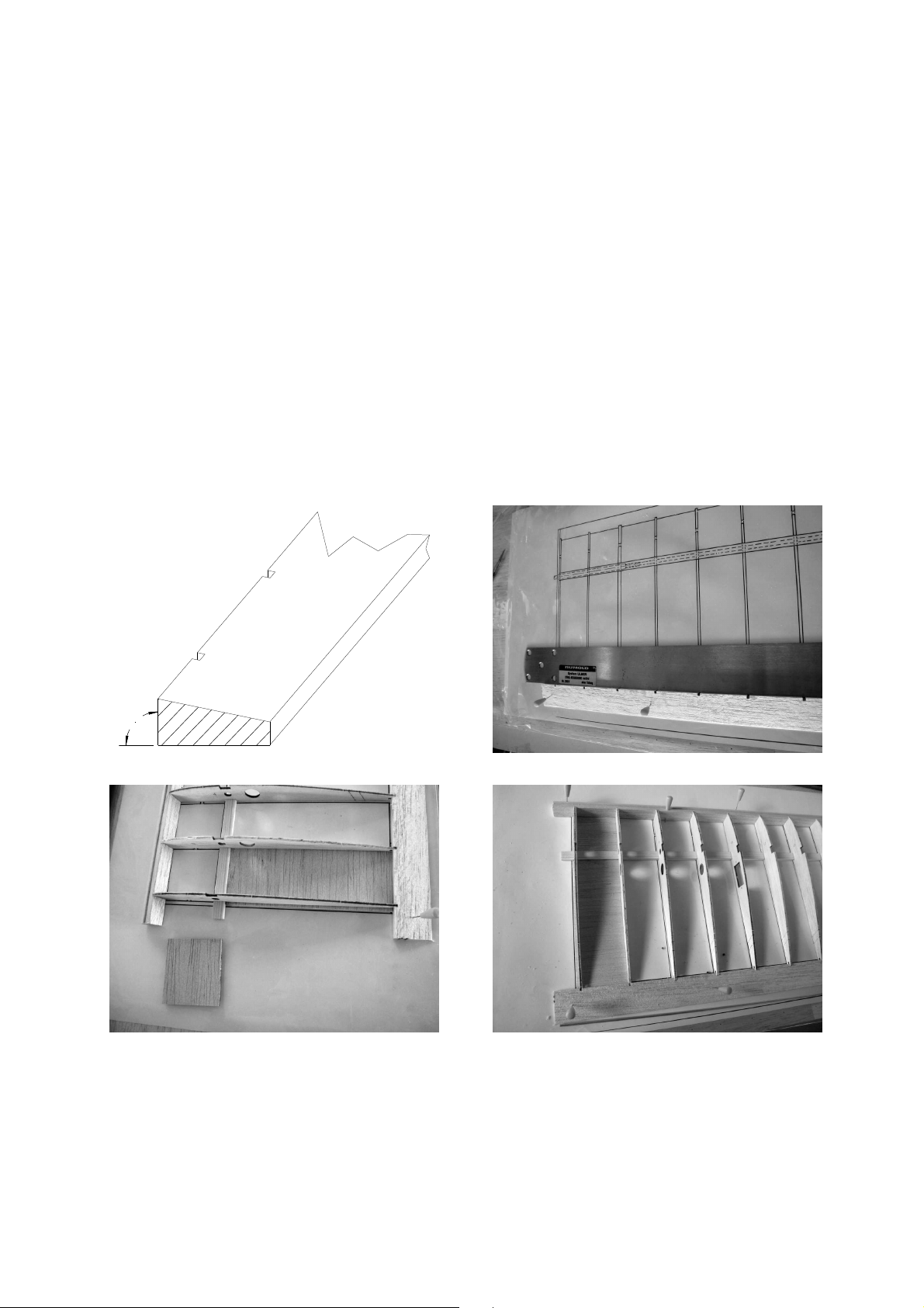
Pin down the leading edge (1), the trailing edge (2) and the main spar (3) over the
plan, checking that the distance between them matches the rib notches. Caution:
the face which is at right-angles to the front edge is the underside. Tip: fit two or
three ribs in the notches, position them carefully over the plan, then pin down the
spar, leading edge and trailing edge. Trim the bottom sheeting (12 and 13) to fit between the leading edge, spar and trailing edge, and pin these parts to the building
board flush with the outside of the second rib (5). The remaining wing ribs (4 - 11)
can now be fitted and glued to the leading edge, spar, trailing edge and sheeting.
Caution: the ribs, leading edge, trailing edge, spar and sheeting must lie absolutely
flat on the building board. Take care to glue the first rib (4) in place exactly straight.
90°
Glue the supplementary rib (5-z) in place, spaced 0.5 mm away from the rib (5) (tip:
fit or glue scrap 0.5 mm sheet between the parts as a spacer). Glue the secondary rib
(10-z) in place in the same way as the supplementary rib (5-z). Glue the top spar to
the structure, ensuring that it reaches the bottom of the notches in the laser-cut ribs.
Slide the joiner rube (15) into the appropriate hole; leave it projecting by about 5 - 6
mm. Cut the aluminium pivot tube (14) to length (approx. 400 mm) and slide it
GRAUPNER GmbH & Co. KG D-73230 KIRCHHEIM/TECK GERMANY
Modifications reserved. No liability for printing errors Id. No. 0061845 04/2010
4

through the holes in the ribs at the trailing edge; leave it projecting by about 10 mm,
and glue it in place with cyano. Glue the gussets (23) to the rib (11) and the leading
and trailing edges, the gussets (24) to the rib (10) and the pivot tube (14), and the
gussets (25) to the ribs (5-z + 10-z) and the pivot tube (14) using cyano.
Glue the spar webs (16 + 17) to the spars on the side facing the leading edge.
When the adhesive has set hard, glue the dowel support (18) to the sheeting (13)
and the spar web (16), with the hole adjacent to the rib (4). Let the glue dry, then drill
a 4.0 mm Ø hole in the leading edge to accommodate the locating dowel (note: the
dowel must lie parallel with the rib (4)).
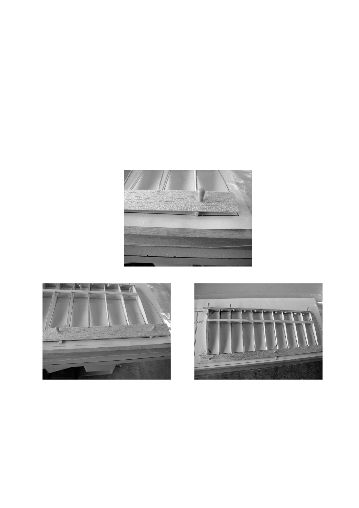
Offer up the leading edge sheet panel (19), and check that its width is correct; trim if
necessary. Apply glue to the contact surfaces of the wing structure. Fit the sheeting
in the recess in the leading edge, and pin it in place using a spare strip of wood to
spread the load, then roll the sheeting back over the ribs and onto the spar. Clamp
the sheet panel to the spar using a packing strip to avoid damaging the surface.
GRAUPNER GmbH & Co. KG D-73230 KIRCHHEIM/TECK GERMANY
Modifications reserved. No liability for printing errors Id. No. 0061845 04/2010
5
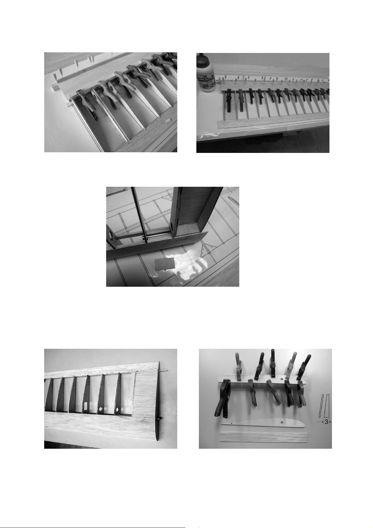
Cut the in-fill piece (20) to length, trim it to fit between the wing joiner tube (15) and
the spar (3), then glue it and the webbing (16 and 17) in place using plenty of UHU
plus (epoxy). Clamp the webbing in place while the glue is hardening.
Cut out the hole for the servo lead in the bottom wing sheeting as shown on the plan.
Trim the upper root sheeting (21) to fit, and glue it in place flush with the outside of
the rib (5). When the glue has set hard, sand back the excess leading and trailing
edge strips and the sheeting until these parts are flush with the rib (4).
Glue the root facing rib (4.1) to the bevelled face of the triangular strip (26).
GRAUPNER GmbH & Co. KG D-73230 KIRCHHEIM/TECK GERMANY
Modifications reserved. No liability for printing errors Id. No. 0061845 04/2010
6
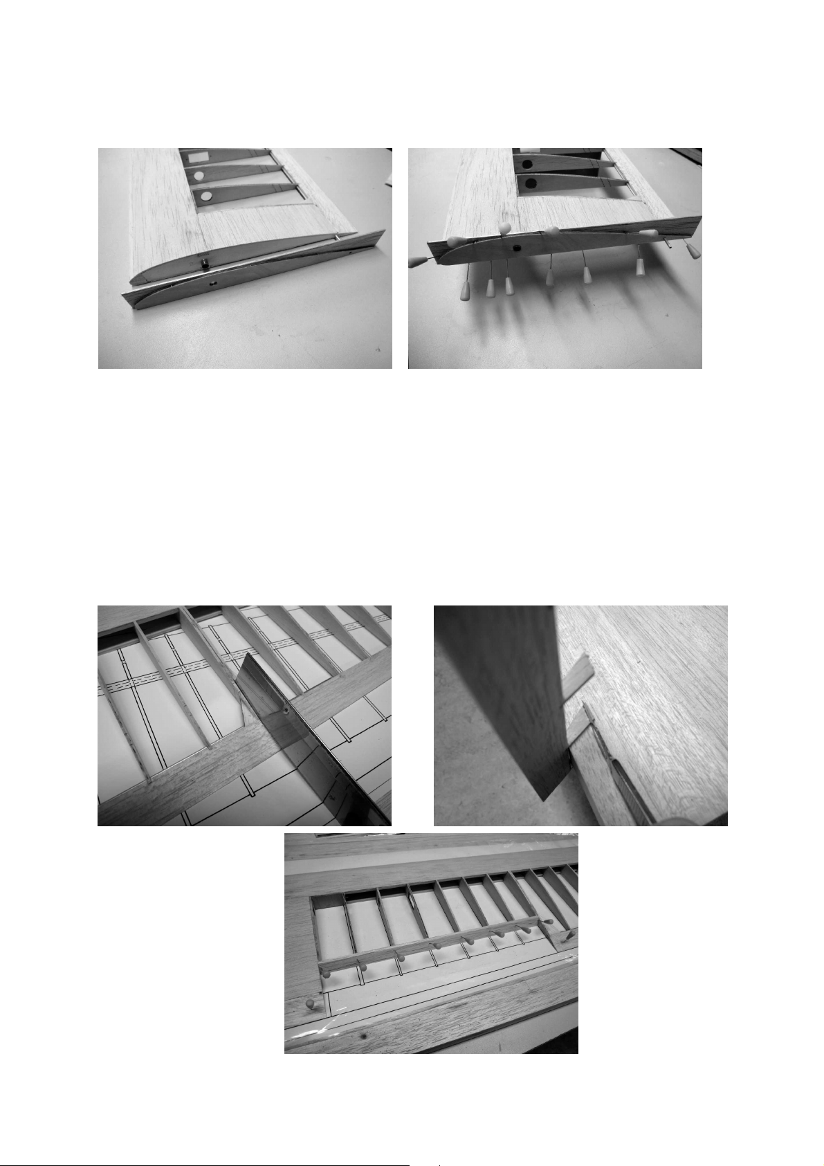
When the glue has set hard, continue the holes in the facing rib (4.1) through the triangular strip (26), and glue this assembly to the rib (4).
Allow the glued joints to set hard, then remove the excess triangular material using a
sharp knife (or balsa plane or chisel) before sanding the edges back flush.
The next step is to cut the recess for the trailing edge airbrake: cut through the trailing edge (2) between the ribs (5; 5-z and 10-z; 10) using a thin sawblade. The cutlines in the ribs are indicated by laser marks; cut along them using a balsa knife. Pin
the wing down over the plan on the building board, cut the recess sealing strip (27) to
length, and glue it to the ends of the ribs, taking care to keep the ribs aligned with the
plan. Trim the sheeting (22) to fit between the ribs (8 and 9) and glue it in place, flush
with the underside of the ribs.
Allow the glue to set hard, then pin down the airbrake on the building board and glue
the leading edge sealing strip (27) to it.
GRAUPNER GmbH & Co. KG D-73230 KIRCHHEIM/TECK GERMANY
Modifications reserved. No liability for printing errors Id. No. 0061845 04/2010
7
When all the glued joints are dry, place the airbrake in the recess and slip the steel
pivot rod (28) through the aluminium tube (14). Sand back the sealing strips (27) to
follow the contour of the ribs.
Caution: take care not to sand into the ribs and change the airfoil section.
The tip panels are assembled in the same way as the wing centre section: fit scrap
wood under the trailing edge (3) at the tip rib (39) to pack it up by 5 mm, and pin it flat
on the building board at the root rib position (29). Fit further packing, using a long
ruler or straight edge to keep it straight. Pin down the spar (3) and leading edge (1),
spaced to match the root rib (29) and the tip rib (39). Glue the ribs (29 - 39) to the
leading edge (1), the spar (3) and the trailing edge (3), keeping them flush with the
strip material. Allow the glue to dry, then lay the leading edge sheeting panel in place
and trim it if necessary. Apply glue to all the contact surfaces, position the sheet
panel (40) in the leading edge recess, and pin it in place using a scrap strip. Roll the
panel back over the ribs, and clamp it to the spar using a spare strip as a spreader.
Saw off the excess leading edge (1), spar (3) and sheeting (40), and sand them flush
with the end ribs (29 + 39). Cut the trailing edge (2) flush at the dihedral break rib
(29). Glue the wingtip (41) to the rib (39) and the trailing edge (2), then sand the trailing edge flush with the wingtip when the glue has set hard. Glue the triangular strips
(42) to the dihedral break ribs (11 + 29) of the centre and tip panels, keeping them
flush at the underside; note the correct angle. Let the glue dry, then cut or plane off
excess material before sanding it back flush with the airfoil. Cut a slot in the triangular
strip and the rib to clear the tip dihedral brace (43), and check that it is a snug fit.
GRAUPNER GmbH & Co. KG D-73230 KIRCHHEIM/TECK GERMANY
Modifications reserved. No liability for printing errors Id. No. 0061845 04/2010
8
 Loading...