

GRAUPNER CHIP Building Instructions
Order No. 4564
BUILDING INSTRUCTIONS
CHIP
For electric motor and three 850 mAh LiPo cells
The model requires a three-function HoTT radio control system
GRAUPNER GmbH & Co. KG D-73230 KIRCHHEIM/TECK GERMANY
Modifications reserved. No liability for printing errors. Id.-Nr. 0062414 3/2011
- 1 -

Please be sure to observe the Safety Notes in the Appendix of these operating instructions. If
you ever pass the model on to another person, the complete operating instructions must be
included with it.
Introduction
The CHIP is an ideal beginner’s hotline model, which offers maximum flying pleasure
for minimum building effort. The model is highly pre-fabricated, but the procedures
described in the following instructions must be carried out with the greatest care to
ensure that the model flies safely and well. The aircraft’s all-up weight must not
exceed 600 g.
RC system accessories
The following items are required in order to operate the model.
MX-12 2.4 GRAUPNER HoTT COMPUTER SYSTEM Order No. 4754
DES 261 BB servo (two required) Order No. 7903
ULTRAMAT 8 Order No. 6411
Transmitter charge lead Order No. 3022
Charge lead with BEC connector Order No. 3037
COMPACT FLY 15 BEC speed controller Order No. 7220
GRAUPNER LiPo flight battery, 3/850 11.1 V / 850 mAh Order No. 7621.3BEC
Essential tools and adhesives
Balsa knife Order No. 980
Screwdriver
Abrasive paper, 320-grit
Side-cutters
Mini flat-nose pliers
Open-ended spanner, 8 mm A/F, allen key, 1.5 mm A/F, allen key, 2 mm A/F
Paper scissors
Adhesive tape
Soldering iron, solder, heat-gun
Cyano-acrylate glue (“cyano”) Order No. 5821
Cyano activator Order No. 953.150
Building instructions
Please read right through these building instructions before you start construction, to
ensure that you have a clear understanding of the sequence of operations required.
Lay out all the components, tools and adhesives for each stage before you start
work, and prepare the model parts as described in the building instructions. When
assembling the components always work on a clean, smooth surface, or cover the
workbench with a layer of soft foam. Use cyano-acrylate and activator as adhesive.
We recommend that you apply the glue to one joint surface, and spray activator on
the mating surface. Take particular care to avoid adhesive running onto your hands
or the model’s surface; immediately wipe off any excess glue using paper towel.
Caution: cyano-acrylate must never come into contact with body parts. Take
particular care to avoid it getting in your eyes; we therefore recommend that
you wear goggles when handling cyano. Store the adhesive well out of the
reach of children. For safety reasons we recommend that you only use the
adhesive stated above.
GRAUPNER GmbH & Co. KG D-73230 KIRCHHEIM/TECK GERMANY
Modifications reserved. No liability for printing errors. Id.-Nr. 0062414 3/2011
- 2 -
Fuselage and tail
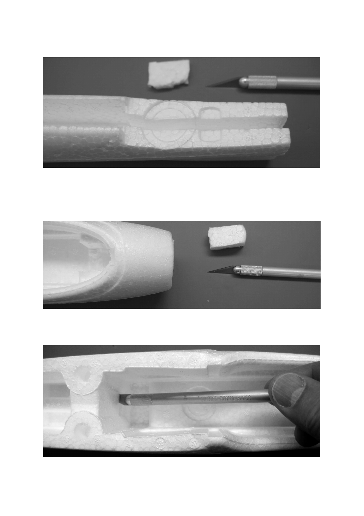
Use a balsa knife to continue the channel for the reinforcement (2) right through to
the end of the fuselage. Tip: use the balsa knife just to cut the side slits, then push
out the scrap SOLIDPOR foam using the strip of spruce (2). Fit the spruce strip and
ensure that it rests completely on the bottom of the fuselage. This is important,
otherwise it will not be possible to push the fin (4) fully into place.
Locate the lug at the front face of the fuselage produced by the moulding process.
Remove this to provide clearance for the power leads of the INLINE 400 electric
motor.
GRAUPNER GmbH & Co. KG D-73230 KIRCHHEIM/TECK GERMANY
Modifications reserved. No liability for printing errors. Id.-Nr. 0062414 3/2011
- 3 -
Cut a 10 x 6 mm opening at the bottom of the fuselage for the servo leads.
Push the strip of spruce (2) through to complete the opening.
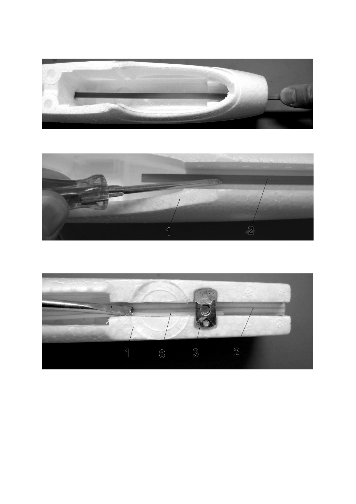
Glue the fuselage reinforcement (2) exactly central in the fuselage (1), and press it
into place. Check carefully that the fuselage is not distorted when you do this.
Roughen the surface of the captive nut (3) using abrasive paper, then glue it in place
using plenty of adhesive. When the glue has set hard, fit the retaining screw (12) in
the nut and pull on it to check that the joint is strong enough.
Use the balsa knife to cut the elevator snake outer sleeve (6) to a length of 440 mm,
and press it into place as shown in the picture. Glue the elevator snake sleeve (6) to
the side of the fuselage reinforcement (2) at the front.
GRAUPNER GmbH & Co. KG D-73230 KIRCHHEIM/TECK GERMANY
Modifications reserved. No liability for printing errors. Id.-Nr. 0062414 3/2011
- 4 -
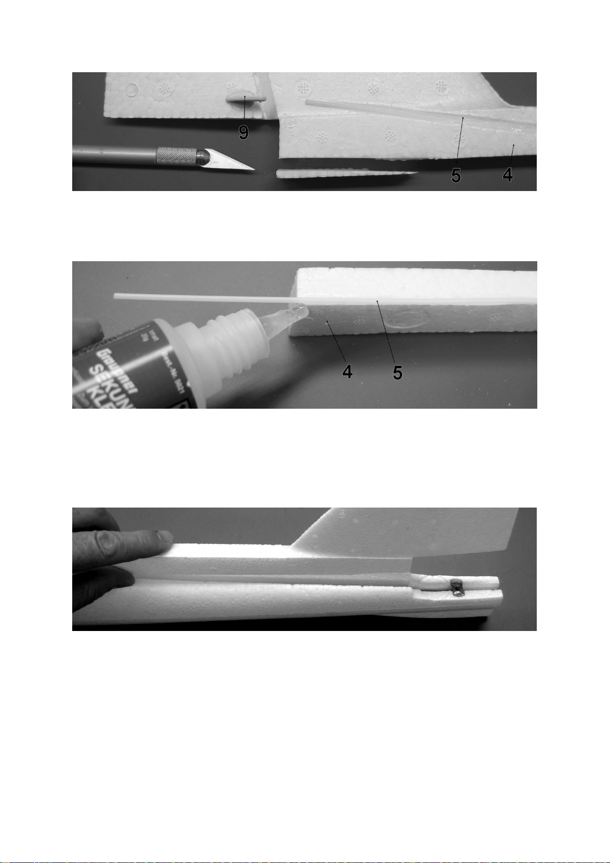
Cut off a 2 mm wide wedge from the fin (4), sand the joint surface of the rudder
snake outer sleeve (5) and glue it in place. Take care to glue the snake sleeve inside
its channel only. Don’t glue the horn (9) in place at this stage.
Glue the snake sleeve (5) to the underside of the fin at the front. Ensure that it ends
flush with the fin; it must not overlap the fuselage reinforcement (2) later, as this
would make it impossible to insert the fin (4) completely.
Temporarily slide the prepared fin into the fuselage; if there is a gap between the
fuselage and the fin, squeeze the fuselage sides together at the top.
The fin can now be glued in place. Caution: don’t use activator for this joint,
otherwise the parts will stick together before you have a chance to position
them correctly.
Apply cyano to the spruce strip (2) and the inside of the fuselage, then slide the fin
briskly into place. Ensure that it ends flush with the top of the fuselage, and makes
contact at the tail end.
GRAUPNER GmbH & Co. KG D-73230 KIRCHHEIM/TECK GERMANY
Modifications reserved. No liability for printing errors. Id.-Nr. 0062414 3/2011
- 5 -
 Loading...