

Page 1
GRAUPNER GmbH & Co. KG D-73230 KIRCHHEIM/TECK GERMANY
We reserve the right to introduce modifications. Not liable for printing errors!
12/2011
1
Re: Order No.9355
9355.M
Instructions
BO 209 MONSUN
For internal combustion motors up to 33 cm³
and
electric motors
Requires a HoTT radio control system with 5 functions
Page 2

GRAUPNER GmbH & Co. KG D-73230 KIRCHHEIM/TECK GERMANY
We reserve the right to introduce modifications. Not liable for printing errors!
12/2011
2
Specification
Wingspan about 2200 mm
Fuselage without spinner about 1660 mm
Wing area about 62 dm²
Tailplane area about 12 dm²
Wing area about 74 dm²
All-up weight depending on equipment about 7700 g
EWD 0-0.5 degrees
Centre of gravity about 100 -110 mm behind the leading
edge
Caution: This model is not a toy!
If you do not have experience with such motorised models, please ask experienced
model flyers for help. If the model is operated without the proper knowledge, injuries
can result. Think of your health and safety.
Important! Before you start the assembly!
Even if you have already built lots of RC models, read these instructions through
carefully and check the parts in the kit for completeness. A lot of effort was made to
keep things as simple as possible without neglecting safety.
Note on the covering sheet
Because of strong changes in the weather (temperature, humidity, et cetera), small
creases can form in the covering sheet. In rare cases, the components can even be
warped. This lies in the nature of wood construction with covering sheet. This can be
corrected as follows using a hair dryer like those available to model builders.
Creases: Blow with hot air and rub with a soft cloth.
Warped area: Gently twist the area against the direction of warping and smooth
it out again using hot air.
Caution! Never use more heat than is absolutely necessary. If the iron is too hot, the
covering sheet will melt and holes will form.
The extensively pre-fabricated model can be built in a very short time. However, the
remaining steps are important and have to be carried out with care. Doing this work
properly determines whether the model will have the prescribed rigidity and flight
characteristics; so please work slowly and precisely!
When putting screws into wood, secure them against loosening by using
casein glue: Squirt casein glue into the drill hole and screw in the screw.
Page 3

GRAUPNER GmbH & Co. KG D-73230 KIRCHHEIM/TECK GERMANY
We reserve the right to introduce modifications. Not liable for printing errors!
12/2011
3
Tips on building the model
• Before assembling the model, it is essential to read the construction diagram and
the instructions all the way through. When using tools, be aware of the possible
dangers.
• Use only suitable cables that are adequate for the electrical currents that occur
during operation.
• Set up the receiver aerial as far as possible away from the cables carrying the
operating current (at least 3 cm).
• Clean residual grease from all connections that are to be glued. This can, for
example, be done through sanding and using a non-relubricating cleaning
solution. The same goes for the surfaces to be painted, in order to make sure that
the paint sticks. Before gluing parts, always roughen the corresponding surfaces
(especially for GRP fuselages) carefully with fine sandpaper and de-grease them
thoroughly, for example with acetone. Otherwise, adequate adhesion is not
assured.
Other required accessories
Internal combustion motor and accessories
Recommendations for internal combustion motor
Motor
Order No.
Capacity
cm³
Propeller
Order No.
Petrol motor
GT 33
2772
33
45x25 cm
1314.18x10"
Recommendations for electric motor
Electric
motor
Order No.
Propeller
Order No.
Drive battery
Order No.
Speed
controller
Order No.
COMPACT
740 Z
7780
45 x 25 cm
1326.22x10
LiPo 3/5200
18.5/5.2Ah
9752.5
COMPACT
CONTROL
90S
7228
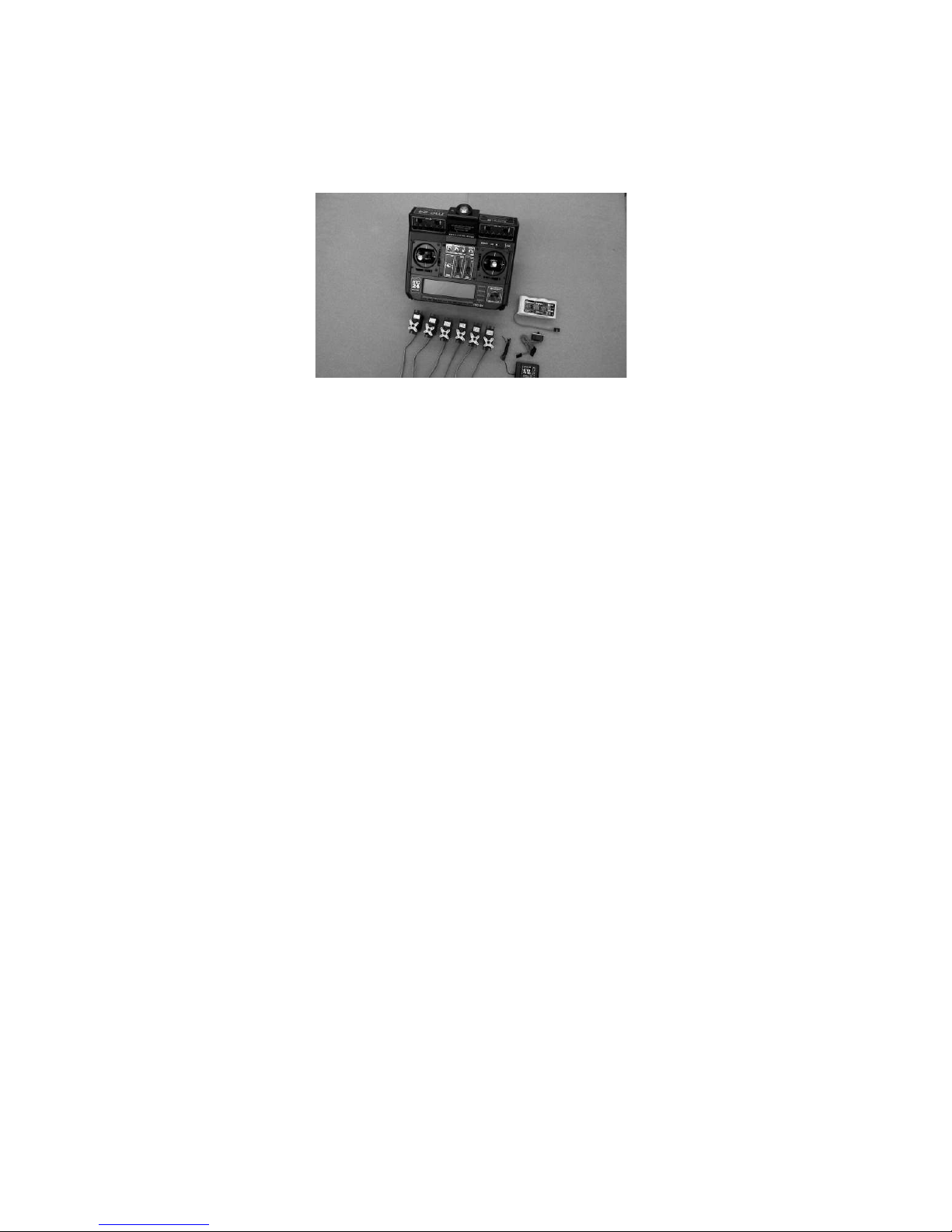
Radio control system
It must have at least 5 control functions and 9 servos. Furthermore, the
transmitter must be capable of servo rotation reversal.
Particularly recommended: Computer-System from MX-20 to MC-24. Servos with
standard dimensions can be installed.
As receiver battery, we recommend: Receiver battery LiFe 2/2900 6.6V JR Order No.
7672.2, which has to be carefully serviced before and after all flight operations. The
Page 4
GRAUPNER GmbH & Co. KG D-73230 KIRCHHEIM/TECK GERMANY
We reserve the right to introduce modifications. Not liable for printing errors!
12/2011
4
capacity of the rechargeable battery can be checked with Graupner Battery GUARD
Order No. 7599. See also the insert included with the battery.
For the connection of the two ailerons and the landing flap servos to the receiver,
extension cables Order No. 3935.18 are required.
Each of the two aileron servo cables needs an extension cable, Order No. 3935.50;
the two landing flap servo cables Order No. 3935.18; the elevator servos Order No.
3935.50; and the bow landing gear servo Order No. 3935.50 for extension.
Receiver and battery: Store in foam material.
Any servo of standard size and an adjusting power of about 50 Ncm can be installed.
Adhesives
Epoxy glue, for example UHU plus schnellfest, Order No. 962
Epoxy glue, for example UHU plus endfest 300, Order No. 950.43
"UHU Holzleim express" casein glue, Order No. 958.60
UHU hart, for example Order No. 534.35
Fast setting glue, for example Order No. 5821
Fast-setting (cyano-acrylate) glue, such as Order No. 5822
Thread lock fluid, for example Order No. 952
Accessories for operation (not included)
Fuel, depending on the motor petrol/oil mixture (see instructions for the motor used)
Fuel hose, for example Order No. 1325.2
Manual fuel pump, for example Order No. 6870
Ignition battery, Order No. 8716.5
Charger cables and chargers for electric aircraft
Required tools (not included)
Various (Phillips) screwdrivers, needle-nose pliers, flat-nose pliers, wire cutter, balsa
knife or razor blade, various drills, pencil, felt marker, soldering iron with fine tip.
Assembly of the BO 209 MONSUN
Page 5
GRAUPNER GmbH & Co. KG D-73230 KIRCHHEIM/TECK GERMANY
We reserve the right to introduce modifications. Not liable for printing errors!
12/2011
5
Wings - tailplane and rudder
Do not begin the assembly until you have familiarised yourself with the components
and the individual construction stages. If you are not satisfied with any component,
report it to your retailer before you start the construction process.
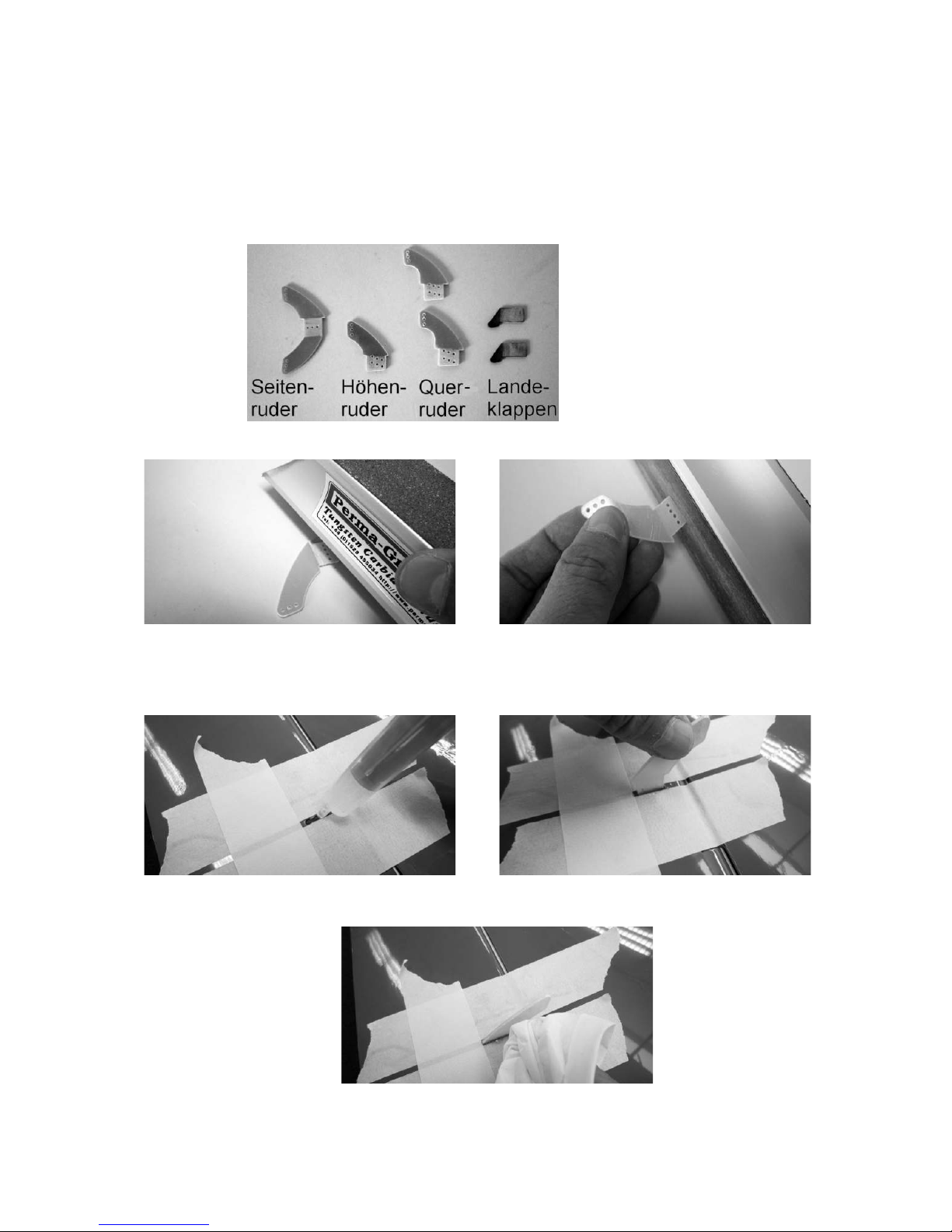
Using sandpaper or sanding block, sand the control horns on the surfaces to be
glued in order to achieve an adequate connection when gluing.
As seen in the photos, unstick the slots in the ailerons, landing flaps, rudder, and
elevators for the GRP control horns; put a dab of glue into the slot, and push the
control horn in until it stops.
Wipe off any excess glue.
Page 6
GRAUPNER GmbH & Co. KG D-73230 KIRCHHEIM/TECK GERMANY
We reserve the right to introduce modifications. Not liable for printing errors!
12/2011
6
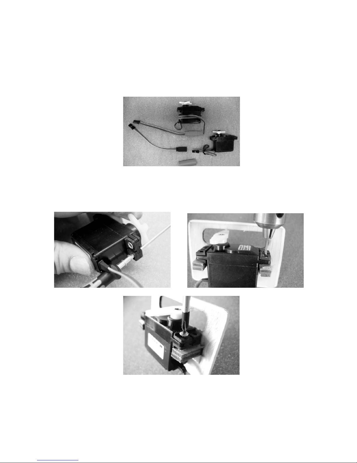
Until the glue hardens, the servos are installed in the corresponding mounts and
fastened into the wing or tailplane.
Extend the servo cables with the corresponding extension cables and secure them
against loosening, for example using a piece of heat-shrink sleeve or a drop of fastsetting glue. Using the RC system, bring the servos in the middle position and install
the servo levers.
Fasten the servo to the attachment block using the screws included with the servos.
To do so, insert the rubber grommets with the brass hollow rivets, collar downward,
into the servo flange. For drilling Ø 1.5 mm holes for the screws, the hollow rivets can
be used as a drilling template. To make it easier to push them in,
the hollow rivets can be placed onto a screwdriver of the proper size.
Now the servo cables are pulled into the wing halves and tailplane halves using a
thin string. Just behind the connector, tie the string to the cable and pull it in so that it
comes out the wing root.
Page 7
GRAUPNER GmbH & Co. KG D-73230 KIRCHHEIM/TECK GERMANY
We reserve the right to introduce modifications. Not liable for printing errors!
12/2011
7
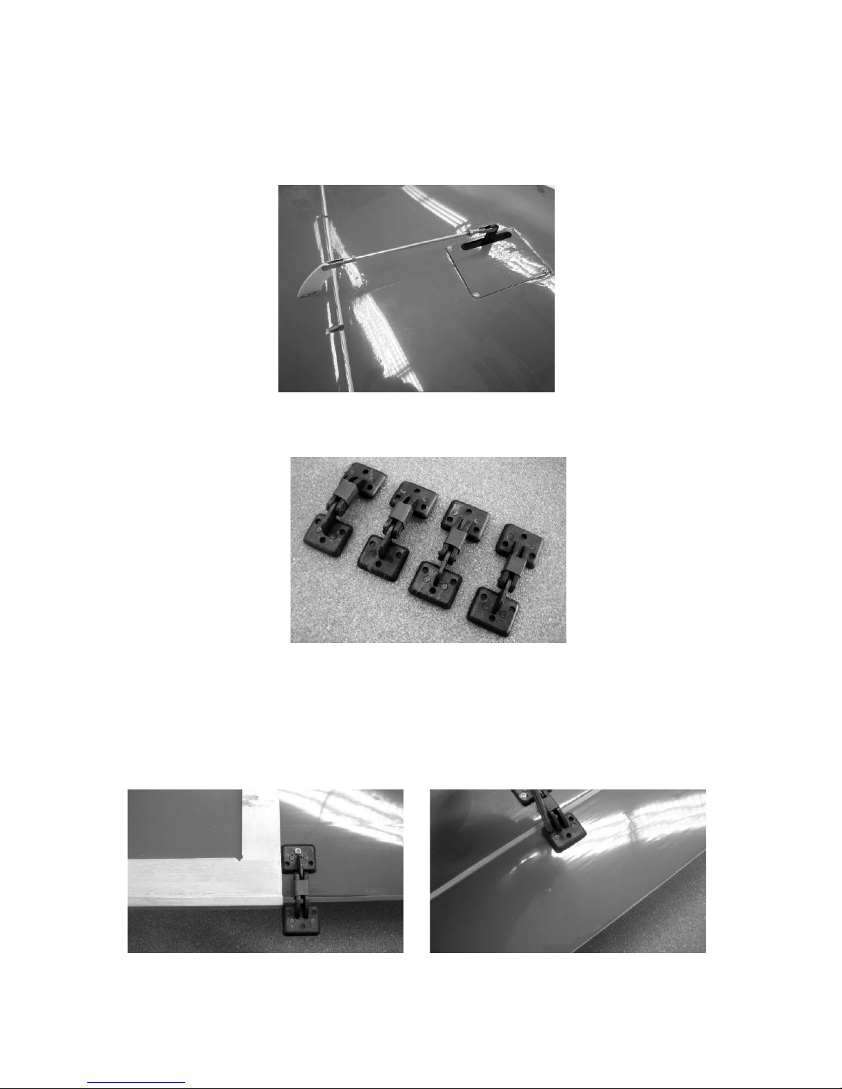
With servo and rudder in neutral position, screw together the lengths of the rods for
the ailerons, landing flaps, and elevators, adjust them, and use thread lock fluid (such
as UHU schraubensicher) and lock nuts to secure them against loosening.
As shown in the photo, secure the hinges for the landing flaps using heat-shrink
tubing.
On the underside of the wings, there are markings indicating where the flap hinges
can be screwed in. Make sure that the axes of rotation of the hinges are all the same
distance from the trailing edge of the wing.
As shown in the photo at the left, a screw is used to fix the hinges in place; then use
an engineer's square or geometric protractor for alignment with the trailing edge, and
fasten the hinges with two more screws. Now push the landing flaps up against the
wings and tape them in place temporarily; align them, and fasten them with screws.
Page 8
GRAUPNER GmbH & Co. KG D-73230 KIRCHHEIM/TECK GERMANY
We reserve the right to introduce modifications. Not liable for printing errors!
12/2011
8
Screw the pushrods together as shown in the following photos.
Adjust the transparent covers of the wing tip lights and use transparent adhesive film
to attach them to the wings.
The bolts used to secure the wing are screwed into the corresponding holes in the
wing roots. Use UHU schraubensicher thread lock fluid to secure the bolts against
loosening.
Page 9

GRAUPNER GmbH & Co. KG D-73230 KIRCHHEIM/TECK GERMANY
We reserve the right to introduce modifications. Not liable for printing errors!
12/2011
9
As shown in the photos, glue the boarding steps together and fasten them to the
wing halves using the plywood tabs.
Later, the boarding steps can be removed in order to transport the wings by pulling
out the plywood tabs.
Fuselage with vertical stabiliser and undercarriage
The vertical stabiliser can either be glued permanently to the fuselage or fastened
removably using two screws.
Page 10

GRAUPNER GmbH & Co. KG D-73230 KIRCHHEIM/TECK GERMANY
We reserve the right to introduce modifications. Not liable for printing errors!
12/2011
10
The tailplane is installed to the fuselage from underneath using three Allen screws.
The screws are screwed in only tight enough to pull the tailplane and vertical
stabiliser firmly against the fuselage.
Attach the pull cables to the control horn of the rudder as shown in the photo.
Then attach the rudder servo to the servo plate at the front of the fuselage.
As shown in the photo, install the pull cables to the servo lever and adjust them so
that the rudder is in the centre position when the servo is in the centre position.
Page 11

GRAUPNER GmbH & Co. KG D-73230 KIRCHHEIM/TECK GERMANY
We reserve the right to introduce modifications. Not liable for printing errors!
12/2011
11
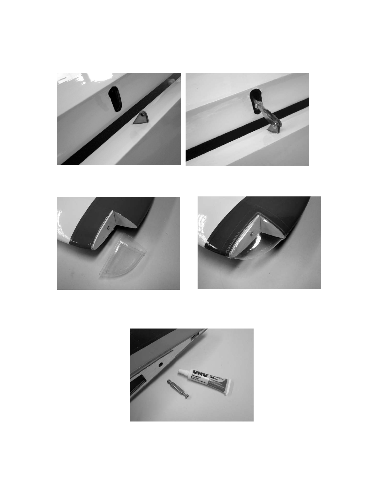
Screw the aero-tow mechanism into the hole just behind the canopy, and apply UHU
thread-lock fluid to prevent the coupling and nut from working loose.
The aluminium part must be shortened enough so that the clevis can move freely;
adjust the rods accordingly. It is best to operate the aero-tow release mechanism
using a momentary switch mounted on the joystick. The servo travel must be set
accordingly.
Fix the nose gear in the brackets by tightening the screw in the collet. Assemble the
pull cables as shown in the photo. As for the rudder, make sure that when the servo
is in the middle position, the nose gear is also in neutral position, meaning that the
model will later roll straight ahead.
Now the nose wheel is installed along with the cover. To do so, unscrew the fork and
re-install it together with the cover. To install the wheel, a hole of about Ø 9mm must
be drilled/filed into the left side of the cover about 5 mm from the underside.
Page 12

GRAUPNER GmbH & Co. KG D-73230 KIRCHHEIM/TECK GERMANY
We reserve the right to introduce modifications. Not liable for printing errors!
12/2011
12
Later the nose gear steering servo and the rudder servo can be connected to the
same receiver socket either using a Y-lead or via a mixer at the transmitter.
The servo for the rudder control horn, as already described in the beginning, is
installed in the servo mount. Fasten it to the side wall of the fuselage with the four
pan-head self-tapping screws.
Prepare the rudder linkages and attach them to the control horn and servo levers as
shown in the photo. Here too, make sure that the elevator is in the neutral position
when the control servo is in the centre position.
Now, using two Allen screws each, the two main undercarriage components
are fastened to the bottom of the fuselage.
To install the two main wheels and covers, a hole must be drilled/filed in each of the
covers about 15 mm from the lower edge and centred with the cut-out. Remember
that a left and a right cover are needed. To reinforce the covers, one of the included
plywood reinforcements is glued to the inside of each cover. Make sure that the drill
holes of the reinforcements and covers line up. This can be done by inserting the
wheel axle.
Page 13

GRAUPNER GmbH & Co. KG D-73230 KIRCHHEIM/TECK GERMANY
We reserve the right to introduce modifications. Not liable for printing errors!
12/2011
13
After the glue has set, the axles together with the wheels and collets are installed and
fastened to the undercarriage components.
Align the covers so that they are fastened parallel to the ground.
Installing the tank and motor
Assembling and installing the fuel tank
Slip a piece of plastic tubing onto the fuel tank clunk pick-up. Push the free end of the
fuel tubing onto one of the tubes in the fuel tank stopper so that the pick-up will be able
to move freely inside the tank later on without binding or jamming when the stopper is
in place. Use a heat-gun or lighter to gently heat the free plastic tubes so that they can
be bent easily. One tube should face down and will be used later to fill the tank; the
other one points upward and serves later as the overflow when the tank is filled. Use a
piece of tubing to extend the two tubes so that they reach to the top and bottom of the
tank.
Now push the tank stopper over the throat of the fuel tank, and tighten the Philips-head
screw to fasten the stopper in place. It is important to tighten the screw so that the tank
is completely sealed. This can be checked by holding the tank under water. Hold it
under water and blow air into it. If the tank is sealed, there will be no air bubbles.
To each stub tube projecting from the
fuel tank, a length of fuel tubing is
connected.
Mark the tubes with a felt marker to show
which runs to the motor, the overflow,
and the filler.
The tube from the clunk is then
connected to the carburettor, while the
overflow is run downward. The fuel filler tube can later be routed out through a drill
hole in the engine bonnet. After filling, it should be sealed with a plug.
Page 14

GRAUPNER GmbH & Co. KG D-73230 KIRCHHEIM/TECK GERMANY
We reserve the right to introduce modifications. Not liable for printing errors!
12/2011
14
The attachment block is fastened with two screws.
The installation of the OS MAX GT 33 is described here, but the process
is the same for other motors.
To install the internal combustion engine, the fuselage is placed on the
undercarriage. Using the Allen screws and aluminium bushing provided, attach the
internal combustion engine to the bulkhead.
Attach the servo lever of the throttle servo to the linkage connector. Make sure that it
can turn without any noticeable play. Servo lever about 13 mm.
Fasten the servo to the board using the screws included with the servo.
The throttle linkage is attached to the carburettor lever using the double-cranked
section. With half open carburettor and servo in the middle position, the pushrod is
fixed to the linkage connector using the grub screw.
Page 15

GRAUPNER GmbH & Co. KG D-73230 KIRCHHEIM/TECK GERMANY
We reserve the right to introduce modifications. Not liable for printing errors!
12/2011
15
The throttle rod is adjusted so that the carburettor is half open when the servo is in
centre position. The servo travel must be adjusted so that the engine stops when the
throttle stick and trim are at the full back position.
Install the rods for the choke flap as shown in the photo. The end is angled so that it
can be activated later through the opening in the engine bonnet. Do not let it get into
the propeller arc.
The silencer is attached to the motor using the included two bolts and seal.
Depending on the motor used - for the silencer outlet, spark plug, cylinder head, et
cetera - it is necessary to cut or file openings in the engine bonnet. Position the
engine bonnet on the fuselage in such a way that there is about 2 mm clearance
between the spinner base plate and the front edge of the bonnet.
To attach the engine bonnet to the fuselage, the four attachment points also have to
be marked on the engine bonnet. To do so, cut four strips of scrap wood and drill a Ø
3 mm hole in each one as shown in the photo.
Now each strip is fastened to the
fuselage using an M3 Allen screw and
taped in place as shown in the photo.
Page 16

GRAUPNER GmbH & Co. KG D-73230 KIRCHHEIM/TECK GERMANY
We reserve the right to introduce modifications. Not liable for printing errors!
12/2011
16
Unscrew the Allen screws, then push up the engine bonnet so that it moves under
the strips and the spinner base plate is about 1.5-2 mm from the engine bonnet. In
this position, mark the four attachment points on the engine bonnet.
The engine bonnet is attached with four the Allen screws.
Installation of the electric motor
The electric motor is attached to the bulkhead using the included motor bulkhead,
bolts, nuts, cylindrical aluminium bushings, and sections of the aluminium pipe.
Page 17

GRAUPNER GmbH & Co. KG D-73230 KIRCHHEIM/TECK GERMANY
We reserve the right to introduce modifications. Not liable for printing errors!
12/2011
17
The distance between bulkhead and spinner base plate should be the same as for
the internal combustion engine. Accordingly, four pieces of equal length must be cut
from the aluminium pipe.
As shown in the photo, the motor then rests upon four stilts. The four hexagonal bolts
must be cut off flush with the nuts.
Depending on the electric motor used, mark the fastening points on the motor
bulkhead and attach the electric motor.
The speed controller for the electric motor is fastened to the bulkhead as shown in
the photo.
Cockpit canopy
Glue the seat backs and pilot figure in the proper positions as shown in the following
photo.
The parts should be affixed using double-sided tape, such as Order No. 2904.
The cockpit canopy is attached using transparent tape all around.
The final work on the model consists of fitting and gluing the navigation lights and
decals. To position the individual name placards correctly, refer to the illustrations on
the carton.
Page 18

GRAUPNER GmbH & Co. KG D-73230 KIRCHHEIM/TECK GERMANY
We reserve the right to introduce modifications. Not liable for printing errors!
12/2011
18
Balancing the BO 209 MONSUN
The completely equipped model, with the fuel tank empty, should balance level when
supported at a point about 100 - 110 mm aft of the leading edge of the wing, ideally
in inverted flight position. If the centre of gravity is correct, the model should balance
out horizontally or with the nose pointing slightly downward. If necessary, adjust the
centre of gravity by shifting the position of the receiver batteries. Before flying the
aircraft, set the transmitter trims to centre and ensure that all the control surfaces are
also exactly centred (in neutral position).
Rudder deflection for normal flying
Ailerons 35 mm up and 15 mm down
Elevators 25 mm up and down
Rudder 75 mm left and right
Landing flaps Take-off 15 mm down
Landing 60 mm down
We recommend that you set exponential values of 30% at the transmitter.
Important:
When assembling the rods, always take care to ensure that they move freely and can
move through their entire controllable path - including trim travel - and are not
mechanically impeded.
When the joystick moves to the right, the rudder must turn to the right (left stick/left
rudder). When the elevator stick is pulled back, toward your stomach, the elevators
must deflect upward (stick forward = elevators down). If the aileron stick is moved to
the right, the right aileron should move upward; the left aileron downward. When the
throttle stick is pushed forward, the motor must run at full power; if the throttle stick
and trim are moved back to their end-points, the engine must stop. If the trim travel is
moved all the way back, the motor must stop. The landing flaps are best activated via
a three-position switch.
All that remains is to wish you many hours of happy flying with your BO 209
MONSUN.
Your Team !
Safety notes and warnings
Regarding motorized aircraft models with internal combustion engines
• Before you first attempt to fly the model, it is essential to carefully read all
the operating and assembly instructions.
• These safety notes are part of these instructions and must be stored
carefully with the operating instructions and, if the model is passed on to
others, they must also be passed on to the next user.
Page 19

GRAUPNER GmbH & Co. KG D-73230 KIRCHHEIM/TECK GERMANY
We reserve the right to introduce modifications. Not liable for printing errors!
12/2011
19
• Motorised models are very demanding and dangerous objects and require
that the user have great expertise, skill, and a sense of responsibility.
• Motorised models are not suitable for persons under 18 years of age.
• They may be operated only under the instruction and supervision of an
adult who is familiar with the attendant hazards.
• The operator of the model must be in full possession of his or her bodily
and mental faculties. As with car driving, operating a model aircraft under
the influence of alcohol or drugs is not permissible under any
circumstances.
• Radio controlled aircraft models may be used only for the purpose intended
by the manufacturer; meaning not as a sporting device designed to carry
people. Any other use is forbidden.
• A model can only work properly and fulfil your expectations if it is built or
assembled with the greatest of care and in accordance with the assembly
instructions. Independent changes in design or materials are not permitted.
To avoid injuring people and damaging property, it is essential to be careful
and thoughtful when operating your model. Nobody would climb into a fullsize sports aircraft and attempt to fly it without undergoing training
beforehand. Model flying is also something that has to be learned! We
suggest that you ask an experienced model flyer for help, or join a model
club or model flight training school. Your local model shop and the
specialist magazines are excellent sources of information.
• Always observe the information on the centre of gravity and on control
surface deflection! The model must be adjusted accordingly.
• Radio control system: Make sure the frequency used is vacant. Do not
switch on until you are sure! Check the RC system frequently; it too is
subject to wear. Radio interference caused by unknown sources can occur
at any time without warning. Your model will then be uncontrollable and
completely unpredictable. Never leave your radio control system
unattended, as another person might pick it up and try to use it. To ensure
proper operation of your RC system, make sure that the batteries are kept
fully charged.
• Do not ignore warnings! They refer to materials and situations, which, if
ignored, can - in extreme cases - result in fatal injury or permanent damage.
• You alone are responsible for the safe operation of your model and motor.
• Questions regarding the safe operation of model and motor can be
answered by your retailer.
• Propellers and all rotating parts that are powered by a motor pose a
constant risk of injury. Do not touch them with any part of your body! For
example, a propeller spinning at high speed can cut off a finger!
• Always keep well clear of the rotational plane of the propeller! You never
know when some part may come loose and fly off at high speed and with
great energy, hitting you or a third party. Make sure that no other object can
come into contact with the rotating propeller.
• Be careful with loose clothing, such as scarves, loose shirts, et cetera: They
can be sucked in by the propeller stream and get in the way of the propeller
itself.
Page 20

GRAUPNER GmbH & Co. KG D-73230 KIRCHHEIM/TECK GERMANY
We reserve the right to introduce modifications. Not liable for printing errors!
12/2011
20
• If there are passers-by or spectators at your flying site, make sure that they
are aware of the dangers inherent in your activity before you start the
motor, and insist that they keep a safe distance away (at least 5 m).
• Model aircraft may be flown only at "normal" outside temperatures,
meaning in a range of - 5º C to + 35º C; more extreme temperatures can lead
to changes, for example in battery capacity and material characteristics, et
cetera.
• Model fuel is poisonous! Do not let it come into contact with eyes or mouth!
Store only in clearly marked containers out of the reach of children.
• Never run the motor in closed rooms, such as basement, garage, et cetera.
Model motors also produce deadly carbon monoxide gas.
• Operate only outdoors!
• Adhesives and paints contain materials which may be hazardous to health
under certain circumstances. You should therefore observe the notes and
warnings supplied by the manufacturers of these materials.
• Model fuel is highly flammable and combustible; keep away from open
flames, excessive heat, any sources of sparks or other things that could
lead to ignition. Do not smoke in the direct vicinity of fuel or fuel fumes.
• During operation, a model motor develops a great deal of heat. Motor and
shock absorbers are therefore very hot during operations and for a while
afterwards. Touching them can result in serious burns. Careful when
making adjustments! Wear protective gloves! In extreme cases, even fires
can be caused.
• While operating the motor, not only poisonous and hot exhaust emanates
from the exhaust pipe but also very hot liquid combustion residue, which
can result in burns.
• After operation, remove residual fuel from the tank and motor.
• Every time you intend to operate your model, check carefully it and
everything attached to it (for example propellers, control surface linkages,
rudders, et cetera) for possible damage. If you find a fault, do not fly the
model until you have corrected it.
• The motor is started with an electric starter, which may be equipped with an
adapter that fits the model. For fixed-wing aircraft, startup aid can also be
provided, for example, by a wooden rod with a piece of water hose attached.
• During operation, model motors may develop noise far greater than 85 dB
(A); always wear protection for your ears. Never start motors without a
silencer. However, even with a silencer, model motors can disturb
neighbours. Don’t run motors when people expect peace and quiet.
• If the propeller is turning while the model is standing on sandy ground, for
instance, the propeller can suck up sand and dust and hurl it around, and it
could get in people's eyes. Wear protective goggles!
• Take care that the spark plug clip and the lead can not get tangled in the
turning propeller or other rotating parts. Check the throttle linkage, too.
• Take particular care when carrying the model with the engine running. Hold
the rotating parts well away from you!
• Always keep an adequate supply of fuel in the tank. Never continue to fly
the model until all the fuel is used up.
• Never fly directly over people.
Page 21

GRAUPNER GmbH & Co. KG D-73230 KIRCHHEIM/TECK GERMANY
We reserve the right to introduce modifications. Not liable for printing errors!
12/2011
21
• Never fly directly towards people.
• Make sure to keep a safe distance from residential areas: at least 1.5 km “as
the crow flies”. It is always best to join a club and fly at the approved model
flying site. Always keep well clear of high-tension overhead cables.
• Whenever working on the engine, make sure that you have secure footing,
and always hold the model securely.
• When starting and landing, the take-off and landing strips should be kept
free of unauthorised people and movable obstacles.
• The model aircraft must be kept constantly in sight during the entire flight. It
must always give way to manned aircraft.
• Never operate your aircraft from public roads, squares, squares, school
playgrounds, parks, or sports grounds, et cetera, and ensure that you are
always in full control of the model.
• To ensure that you can stop your engine at any time, the throttle must be
adjusted so that the carburettor barrel closes completely when the throttle
stick and trim are moved to their end points. If this does not work, pinch the
fuel line between your fingers or pull off the connecting tube to the tank.
Never try to stop the engine by grasping the flywheel, propeller, or spinner!
• All model fliers should take care to ensure that the public safety, especially
that of people and property, as well as orderly flying operations, are not
endangered or disturbed.
• In legal terms, model aircraft are classed as aircraft and as such are subject
to legal regulations and restrictions that must be observed.
• The brochure “Modellflugrecht, Paragrafen and mehr” (Model Aviation Law,
Legal Requirements and more), Order No. 8034.02 contains a summary of all
these rules, and your local model shop should also have a copy which you
can read. For models with internal combustion engines, it is necessary, for
example, to have the landowner's permission for flights, and insurance is
also mandatory. There are also regulations concerning your radio control
system that must be observed.
• These notes are intended only to make you aware of the many dangers and
hazards that can arise if you work carelessly or irresponsibly. If you take
reasonable care, model flying is a highly creative, instructive, and relaxing
pastime.
• The extensively pre-fabricated model can be built in a very short time.
However, the remaining steps are important and have to be carried out with
care. Doing this work properly determines whether the model will have the
prescribed rigidity and flight characteristics; so please work slowly and
precisely!
•
Important safety notes
You have acquired a kit that can be assembled into a fully working RC model when
fitted out with suitable accessories. However, GRAUPNER has no control over
whether you observe the instructions for the installation and operation of the model or
the use and maintenance of the associated components. For this reason
GRAUPNER assumes no liability for loss, damage, or costs, which are incurred due
to the incorrect use of our products or due to improper behaviour on the part of the
user, or which are connected with such operation in any way. Unless otherwise
Page 22

GRAUPNER GmbH & Co. KG D-73230 KIRCHHEIM/TECK GERMANY
We reserve the right to introduce modifications. Not liable for printing errors!
12/2011
22
prescribed by binding law, the obligation of GRAUPNER to pay compensation for any
reason whatsoever (including personal injury, death, damage to buildings, damage
due to loss of business or turnover, interruption of business, or other direct or indirect
consequent damage) stemming from the operation of the model is excluded.
The total liability in all cases and under all circumstances is limited to the amount of
money that you actually paid for this model.
This model is started up and operated at the sole and exclusive risk of the
operator. To avoid injuring people and damaging property, it is essential to be
careful and thoughtful when operating your model.
According to the new regulation of §103 paragraph 3 of the LuftVZO (German
Aviation Approvals Office), all model aircraft - whether slow flyer, park flyer, glider, or
model aircraft propelled by any form of power plant - must be insured before the
model is operated. Therefore, you should purchase special RC model liability
insurance. Your local model shop will be glad to advise you.
These safety notes must be kept in a safe place, and, if you ever sell the model, must
be passed on to the buyer.
Manufacturer’s declaration:
If material defects or manufacturing faults should arise in a product distributed by us
in the Federal Republic of Germany and purchased by a consumer (§ 13 BGB), we,
Graupner GmbH & Co. KG, Kirchheim/Teck, Henriettenstraße 94-96, Germany,
acknowledge the obligation to correct those defects within the limitations described
below.
The consumer is not entitled to make claims under this manufacturer’s declaration if
the failure in the usability of the product is due to natural wear, use under competition
conditions, incompetent or improper use (including incorrect installation), or external
influences.
This manufacturer’s declaration does not affect the consumer’s legal or contractual
rights regarding defects arising from the purchase contract between the consumer
and the vendor (dealer).
Extent of the guarantee
If a claim is made under guarantee, we undertake at our discretion to repair or
replace the defective goods. We will not consider further claims, especially for
reimbursement of costs relating to the defect (such as installation / removal costs)
and compensation for consequent damages unless they are allowed by statute. This
does not affect claims based on legal regulations, especially according to product
liability law.
Guarantee requirements
The purchaser is required to make the guarantee claim in writing and must enclose
original proof of purchase (such as invoice, receipt, delivery note) and this guarantee
card. The purchaser must send the defective goods to us at his own cost, to the
above-mentioned address.
Page 23

GRAUPNER GmbH & Co. KG D-73230 KIRCHHEIM/TECK GERMANY
We reserve the right to introduce modifications. Not liable for printing errors!
12/2011
23
The purchaser should state the material defect or manufacturing fault or the
symptoms of the fault in as accurate a manner as possible so that we can check
whether our guarantee obligation is applicable.
The goods are transported from the consumer to us and from us to the consumer at
the risk of the consumer.
Duration of validity
This declaration only applies to claims made to us during the claim period as stated
in this declaration. The claim period is 24 months from the date of purchase of the
product by the consumer from a dealer in the Federal Republic of Germany (date of
purchase). If a defect arises after the end of the claim period, or if the evidence or
documents required according to this declaration in order to make the claim valid are
not presented until after this period, then the consumer forfeits any rights or claims
from this declaration.
Limitation by lapse of time
If we do not acknowledge the validity of a claim that is properly made under this
declaration within the claim period, all claims based on this declaration expire after
six months from the time of claim, but not before the end of the claim period.
Applicable law
This declaration, and the claims, rights and obligations arising from it, are based
exclusively on the applicable German Law, without the norms of international private
law, and excluding UN retail law.
The following items must be observed:
• Before you fly the model, check that the radio control system is working reliably,
and that all connections are secure.
• If you intend to use dry cells as a power supply, please note that they must never
be recharged. Only rechargeable batteries can be re-charged.
• The batteries must be charged, and the range of the radio control system must
have been checked. In particular, the transmitter and receiver batteries must be
charged before each take-off.
• Ensure that the channel you intend to use is not already in use. Never fly the
model if you are not certain that your channel is free.
• Observe the instructions and information regarding your radio control system and
accessories.
• Ensure that the servos are not mechanically obstructed at any point in their travel.
• Dry cells and rechargeable batteries must never be short-circuited.
• Remove all batteries before transporting and storing the model.
• Do not subject the model to intense humidity, heat, cold, or to dirt.
• Protect the model and RC equipment against damage during transport.
Page 24

GRAUPNER GmbH & Co. KG D-73230 KIRCHHEIM/TECK GERMANY
We reserve the right to introduce modifications. Not liable for printing errors!
12/2011
24
Pre-flight check
Check for correct functioning and range before every flight. To do so, screw in the
transmitter aerial and extend it fully. Then switch on the transmitter, followed by the
receiver. At an appropriate distance, make sure that all the control surfaces are
working properly and deflecting in the correct direction.
Repeat the check with the motor running, while someone holds the model securely
for you.
The first time you control a model aircraft, it is best to ask an experienced person to
help you with the pre-flight check and during the first few flights.
Care and maintenance
• Clean the model carefully after each use. Also remove any dirt from the propeller.
Clean the model and the RC components using suitable cleaning agents only.
Ask your model shop for information.
• If the model is not to be operated for a considerable time, all the moving parts
must be cleaned and re-lubricated.
 Loading...