

Page 1

GRAUPNER GmbH & Co. KG D-73230 KIRCHHEIM/TECK GERMANY
Keine Haftung für Druckfehler. Technische Änderungen vorbehalten! #0060384 04/2009
1
Montageanleitung für das Modell BERNHARD GRUBEN Best.-Nr.: 2027
Hinweis zur Erstauflage
Aus liefertechnischen Gründen ist bei der Erstauflage des Modells anstatt dem ABS-Rohr Ø5/4mm und
dem ABS-Rundprofil Ø4mm von den Abmaßen gleiches Alu-Rohr und Messing Rundprofil beigelegt
worden. Das Messingrundprofil sollte gelötet, bzw. mit 2-Komponeten Expoydkleber geklebt werden. Das
Alu-Rohr lässt sich mit Sekundenkleber verkleben.
Geschichte des Originals
Die vier Schiffe der 23,1m Klasse wurden in den Jahren 1996 und 97 für die DGzRS auf der SchweersWerft in Bardenfleth gebaut. Im Oktober 1996 wurden die Hermann Rudolf Meyer und die Hans
Hackmack gemeinsam getauft und dann fast genau ein Jahr später die Bernhard Gruben und die Theo
Fischer. Diese Schiffe wurden zu Ehren des Vormanns und dem Maschinisten der Alfried Krupp, die im
Januar 1995 bei einem Unfall auf hoher See ums Leben gekommen sind, so benannt. Diese
Kreuzerklasse sind die ersten Schiffe der DGzRS die für den Gasschutzbetrieb ausgelegt sind und auch
die ersten Schiffe mit einer geschlossenen Brücke. Seit 05.08.1997 wird die Bernhard Gruben auf der
Rettungsstation Norderney eingesetzt.
Beschreibung des Modells
• Bausatz für den erfahrenen Modellbauer
• Rumpf, Deck und Teile der Aufbauten aus tiefgezogenem ABS und CNC-bearbeitet
• Viele Aufbau- und Decksteile aus gelasertem ABS
• Kompletter Beschlagsatz enthalten, bestehend aus Spritzgussteilen und tiefgezogenen bzw.
gelaserten ABS-Teilen, sowie Messingrelingstützen, beleuchteten Suchscheinwerfern usw.
• Umfangreicher Dekorsatz enthält Kennzeichen aller 4 Typschiffe
• Lieferumfang: tiefgezogene ABS-Teile für Rumpf, Decks, Wellenbrecher, Aufbauten, Bügelmast und
andere Teile, gelaserte ABS-Teile für Aufbauten, Treppen, Winden, Fensterrahmen, Lüftungsgitter,
Heckkästen und andere Teile, gelaserte Holzteile für Innenspanten und Verstärkungen und
Schiffsständer, kompletter Beschlagsatz, fertige Mechanik für die Aussetz- und Aufnahmemechanik,
Mechanikteile für das Öffnen und Schließen der Heckklappe
• Tochterboot Johann Fidi ist nicht im Lieferumfang von 2027 enthalten und ist unter 2027.100 separat
erhältlich
• Umfangreicher und fein detaillierter Bausatz für den erfahrenen Modellbauer, der wieder so richtig
bauen möchte. Trotzdem wird durch die werkseitige CNC-Bearbeitung und die vielen Laserteile die
Bauzeit bei den langwierig und schwer zu erstellenden Bauteilen stark verkürzt.
• Originalgetreuer Nachbau der 23m Kreuzer nach originalen Unterlagen der Deutschen Gesellschaft
zur Rettung Schiffbrüchiger (www.dgzrs.de).
Technische Daten
Länge ca. 1160 mm
Breite ca. 300 mm
Gesamthöhe ca. 640 mm
Gesamtgewicht mit RC ca. 10 kg
Maßstab ca. 1:20
Herstellererklärung der Fa. Graupner GmbH & Co KG
Inhalt der Herstellererklärung
Sollten sich Mängel an Material oder Verarbeitung an einem von uns in der Bundesrepublik Deutschland
vertriebenen, durch einen Verbraucher (§ 13 BGB) erworbenen Gegenstand zeigen, übernehmen wir, die
Fa. Graupner GmbH & Co KG, Kirchheim/Teck im nachstehenden Umfang die Mängelbeseitigung für den
Gegenstand.
Rechte aus dieser Herstellererklärung kann der Verbraucher nicht geltend machen, wenn die
Beeinträchtigung der Brauchbarkeit des Gegenstandes auf natürlicher Abnutzung, Einsatz unter
Wettbewerbsbedingungen, unsachgemäßer Verwendung (einschließlich Einbau) oder Einwirkung von
außen beruht.
Page 2

GRAUPNER GmbH & Co. KG D-73230 KIRCHHEIM/TECK GERMANY
Keine Haftung für Druckfehler. Technische Änderungen vorbehalten! #0060384 04/2009
2
Diese Herstellererklärung lässt die gesetzlichen oder vertraglich eingeräumten Mängelansprüche und
-rechte des Verbrauchers aus dem Kaufvertrag gegenüber seinem Verkäufer (Händler) unberührt.
Umfang der Garantieleistung
Im Garantiefall leisten wir nach unserer Wahl Reparatur oder Ersatz der mangelbehafteten Ware.
Weitergehende Ansprüche, insbesondere Ansprüche auf Erstattung von Kosten im Zusammenhang mit
dem Mangel (z.B. Ein-/Ausbaukosten) und der Ersatz von Folgeschäden sind – soweit gesetzlich
zugelassen – ausgeschlossen. Ansprüche aus gesetzlichen Regelungen, insbesondere nach dem
Produkthaftungsgesetz, werden hierdurch nicht berührt.
Voraussetzung der Garantieleistung
Der Käufer hat den Garantieanspruch schriftlich unter Beifügung des Originals des Kaufbelegs (z.B.
Rechnung, Quittung, Lieferschein) und dieser Garantiekarte geltend zu machen. Er hat zudem die defekte
Ware auf seine Kosten an die folgende Adresse einzusenden.
Fa. Graupner GmbH & CO KG, Serviceabteilung,
Henriettenstr.94 -96, D 73230 Kirchheim/Teck
Der Käufer soll dabei den Material- oder Verarbeitungsfehler oder die Symptome des Fehlers so konkret
benennen, dass eine Überprüfung unserer Garantiepflicht möglich wird.
Der Transport des Gegenstandes vom Verbraucher zu uns als auch der Rücktransport erfolgen auf
Gefahr des Verbrauchers.
Gültigkeitsdauer
Diese Erklärung ist nur für während der Anspruchsfrist bei uns geltend gemachten Ansprüche aus dieser
Erklärung gültig. Die Anspruchsfrist beträgt 24 Monate ab Kauf des Gerätes durch den Verbraucher bei
einem Händler in der Bundesrepublik Deutschland (Kaufdatum). Werden Mängel nach Ablauf der
Anspruchsfrist angezeigt oder die zur Geltendmachung von Mängeln nach dieser Erklärung geforderten
Nachweise oder Dokumente erst nach Ablauf der Anspruchsfrist vorgelegt, so stehen dem Käufer keine
Rechte oder Ansprüche aus dieser Erklärung zu.
Verjährung
Soweit wir einen innerhalb der Anspruchsfrist ordnungsgemäß geltend gemachten Anspruch aus dieser
Erklärung nicht anerkennen, verjähren sämtliche Ansprüche aus dieser Erklärung in 6 Monaten vom
Zeitpunkt der Geltendmachung an, jedoch nicht vor Ende der Anspruchsfrist.
Anwendbares Recht
Auf diese Erklärung und die sich daraus ergebenden Ansprüche, Rechte und Pflichten findet
ausschließlich das materielle deutsche Recht ohne die Normen des Internationalen Privatrechts sowie
unter Ausschluss des UN-Kaufrechts Anwendung.
Wichtige Sicherheitshinweise
Sie haben ein Modell erworben, aus dem – zusammen mit entsprechendem geeignetem Zubehör – ein
funktionsfähiges RC-Modell fertiggestellt werden kann. Die Einhaltung der Montage- und
Betriebsanleitung im Zusammenhang mit dem Modell sowie die Installation, der Betrieb, die Verwendung
und Wartung der mit dem Modell zusammenhängenden Komponenten können von GRAUPNER nicht
überwacht werden. Daher übernimmt GRAUPNER keinerlei Haftung für Verluste, Schäden oder Kosten,
die sich aus dem fehlerhaften Betrieb, aus fehlerhaftem Verhalten bzw. in irgendeiner Weise mit dem
Vorgenannten zusammenhängend ergeben. Soweit vom Gesetzgeber nicht zwingend vorgeschrieben, ist
die Verpflichtung der Firma GRAUPNER zur Leistung von Schadensersatz, aus welchem Grund auch
immer ausgeschlossen (inkl. Personenschäden, Tod, Beschädigung von Gebäuden sowie auch Schäden
durch Umsatz- oder Geschäftsverlust, durch Geschäftsunterbrechung oder andere indirekte oder direkte
Folgeschäden), die von dem Einsatz des Modells herrühren.
Die Gesamthaftung ist unter allen Umständen und in jedem Fall beschränkt auf den Betrag, den Sie
tatsächlich für dieses Modell gezahlt haben.
Die Inbetriebnahme und der Betrieb des Modells erfolgt einzig und allein auf Gefahr des
Betreibers. Nur ein vorsichtiger und überlegter Umgang beim Betrieb schützt vor Personen- und
Sachschäden.
Prüfen Sie vor dem ersten Einsatz des Modells, ob Ihre Privat-Haftpflichtversicherung den Betrieb von
Modellschiffen dieser Art mit einschließt. Schließen Sie gegebenenfalls eine spezielle RC-Modell-
Page 3

GRAUPNER GmbH & Co. KG D-73230 KIRCHHEIM/TECK GERMANY
Keine Haftung für Druckfehler. Technische Änderungen vorbehalten! #0060384 04/2009
3
Haftpflichtversicherung ab.
Diese Sicherheitshinweise müssen unbedingt aufbewahrt werden und müssen bei einem Weiterverkauf
des Modells an den Käufer weitergegeben werden.
Folgende Punkte müssen unbedingt beachtet werden:
• Das Modell ist nicht für Kinder unter 14 Jahren geeignet.
• Die hervorstehenden Teile an dem Modell können scharf sein und die Antennen bzw. Masten können
Augenverletzungen hervorrufen.
• Beachten Sie beim Einsatz von Werkzeugen die möglichen Gefahren durch diese.
• Das Modell niemals betreiben, wenn sich Menschen und Tiere im Wasser befinden! Da, bedingt
durch die hohe Geschwindigkeit des Modells, eine erhebliche Verletzungsgefahr für diese besteht.
• Lassen Sie Ihr Modell nicht in Naturschutz-, Landschaftsschutz-, oder Gewässerschutzgebieten
fahren. Informieren Sie sich bei Ihrer Gemeinde über die für den Schiffsmodellbau freigegebenen
Gewässer.
• Fahren Sie niemals im Salzwasser.
• Fahren Sie niemals bei widrigen Witterungsbedingungen, wie z.B. Regen, Gewitter, stärkerem Wind
sowie höherem Wellengang, Strömung des Gewässers usw..
• Beachten Sie die Empfehlungen und Hinweise zu Ihrer Fernsteuerung und Zubehörteilen.
• Kontrollieren Sie, bevor Sie das Modell fahren lassen, dieses auf eine sichere Funktion der
Fernsteuerung sowie die Steckverbindungen auf sichere un d feste Verbindung.
• Trockenbatterien zur Stromversorgung dürfen niemals nachgeladen werden. Nur Akkus dürfen
nachgeladen werden.
• Die Reichweite der Fernsteuerung muss vor Fahrtbeginn überprüft worden sein. Laufen Sie hierzu mit
eingeschaltetem Modell ca. 100 m vom Sender weg, ein Helfer bedient währenddessen den Sender.
Hierbei müssen alle Funktionen problemlos ausgeführt werden können.
• Prüfen Sie, ob der von Ihnen genutzte Kanal frei ist. Fahren Sie niemals, wenn Sie sich nicht sicher
sind, ob der Kanal frei ist.
• Beachten Sie, dass Funkgeräte oder Sendeanlagen die Funktion des Modells stark stören können.
Achten Sie möglichst darauf, dass keines dieser Geräte in der Nähe betrieben wird während Sie das
Modell betreiben.
• Arbeiten Sie nur an den Antriebsteilen, wenn der Fahrakku nicht angeschlossen ist.
• Bei angeschlossenem Fahrakku dürfen Sie und andere Personen niemals in den Bereich der
drehenden Antriebsteile, besonders der Schiffsschrauben, kommen .
• Die empfohlene Betriebsspannung nicht übersteigen. Eine höhere Spannung kann zum Überhitzen
der Motoren bzw. des Fahrtreglers führen oder die elektrischen Leitungen können durchschmoren.
Dadurch kann das Modell zerstört werden.
• Achten Sie auf Leichtläufigkeit aller Antriebskomponenten. Dies gilt besonders während des
Fahrbetriebs, da sich Blätter und andere Dinge im Antrieb verfangen können. In einem solchen Fall
können die Motoren bzw. der Fahrtregler durch Überlast zerstört werden.
• Die Batterien und Akkus dürfen nicht kurzgeschlossen werden, sowie nicht direkt dem Wasser
ausgesetzt werden.
• Entnehmen Sie den Fahrakku und die Senderbatterien bzw. -akkus bei Nichtgebrauch des Modells.
• Setzen Sie das Modell nicht starker Luftfeuchtigkeit, Hitze, Kälte sowie Schmutz aus.
• Sichern Sie das Modell und den Sender beim Transport gegen Beschädigung sowie Verrutschen.
• Betreiben Sie niemals das Modell an einem stark bewegten Wasser (z.B. Fluss), da bei einem evtl.
Defekt das Modell abtreiben kann.
• Bringen Sie bei einer evtl. Bergung des Modells sich nicht selbst sowie andere in Gefahr.
• Achten Sie besonders auf die Wasserdichtheit des Modells. Ein Modellboot wird bei entsprechendem
Wassereinbruch sinken. Kontrollieren Sie das Modell vor jeder Fahrt, ob irgendeine Beschädigung
vorliegt und ob Wasser durch die Antriebs- bzw. Ruderwellen eindringen kan n.
• Lassen Sie das Modell nach Gebrauch gut austrocknen.
• Kontrollieren Sie unbedingt während der ersten Fahrt mehrmals, ob die Wellenanlagen wasserdicht
sind. Wenn Wasser eindringt, demontieren Sie die Wellen und schmieren die Stevenrohre mit
ausreichend Fett (Best.-Nr. 570) nach.
• HINWEIS: die im Modell verbauten Elektromotoren dürfen nicht im Hausmüll entsorgt werden, sie
müssen demontiert werden und separat an der zuständigen Entsorgungsstelle abgegeben werden.
• HINWEIS: bei parallel angeschlossenen Fahrakkus dürfen diese nur während des Fahrbetriebs
angeschlossen sein, da ohne Last sonst Wechselwirkungen zwischen den beiden Akkus auftreten und
diese die Akkus beschädigen könnten. Stecken Sie daher die Akkus erst bei Beginn des Fahrbetriebs
an und bei Beendigung wieder ab. Keinesfalls dürfen die Akkus mit angeschlossenem Parallelkabel
gelagert werden.
Page 4

GRAUPNER GmbH & Co. KG D-73230 KIRCHHEIM/TECK GERMANY
Keine Haftung für Druckfehler. Technische Änderungen vorbehalten! #0060384 04/2009
4
Hinweise zum Bau des Modells
• Vor dem Bau des Modells sollte man unbedingt den Bauplan und die Anleitung bis zum Schluss
studieren. Die Stückliste ist als Hilfsmittel zu benutzen. Anleitung und Stückliste sind weitgehend in
der Reihenfolge des Zusammenbaus gehalten.
• Dieses Modell ist für den Modellbauprofi ausgelegt und deshalb werden nicht alle Arbeitsschritte
aufgeführt. Auch der Bauablauf wird hier nur als grober Ablauf angegeben. Die relevanten und
kritischen Arbeitsschritte sind aber genau und ausführlich beschrieben.
• Achten Sie bei der Verwendung von Werkzeugen auf die möglichen Gefahren.
• Zum Feinschliff der Oberflächen ist Nassschleifpapier mit der Körnung 600 geeignet, auch für Flächen
die später lackiert werden sollen, ist dieses Schleifpapier mit dieser Körnung optimal geeignet.
• Wenn in das Modell zusätzliche Sonderfunktionen eingebaut werden sollen, müssen diese vor
Baubeginn mit eingeplant werden.
• Entstören Sie die Elektromotoren und die Wasserpumpen mit einem 470 nF Kondensator (Best.-Nr.
3588), indem Sie die beiden Motoranschlüsse mit dem Kondensator verbinden.
• Die elektrischen Leitungen sauber, ohne Kreuzungen verlegen. Es darf keinesfalls die Plusleitung mit
der Minusleitung elektrisch in Kontakt kommen können. Fixieren Sie alle Kabel so, dass sie nicht in
die drehenden Teile des Antriebs kommen können, z.B. mit Kabelbindern.
• Verwenden Sie nur geeignete Kabel, die den im Betrieb auftretenden Stromstärken genügen. Mit den
empfohlenen Komponenten reicht ein Kabelquerschnitt von Ø2,5 mm² (z.B. Best.-Nr. 3689).
• Verlegen Sie die Empfangsantenne möglichst weit entfernt von den Fahrstrom leitenden Kabeln
(mindestens 3 cm).
• Verwenden Sie zum Schmieren der Wellenanlage nur Fett oder Öl, welches das Wasser nicht
gefährdet bzw. verschmutzt (Fett Best.-Nr.: 570, Öl Best.-Nr. 206).
• Säubern Sie jede Klebeverbindung von Fettresten, bevor Sie diese verkleben. Dies kann durch
anschleifen und säubern mit einem nicht nachfettenden Spülmittel oder Spiritus erfolgen. Das gleiche
gilt für die zu lackierenden Oberflächen, um eine gute Haltbarkeit der Farbe zu erreichen.
• Empfohlene Klebstoffe bei einer Verbindung untereinander:
Material – Material Geeignete Klebstoffe
Kunststoff Motorträger - Holz Sekundenkleber
ABS - Holz Sekundenkleber, UHU acrylit
ABS - ABS Sekundenkleber, UHU acrylit, UHU plast spezial
ABS - Metall Sekundenkleber, UHU acrylit
Holz - Holz Sekundenkleber, UHU hart, Weißleim
Holz - Metall Sekundenkleber
Beachten Sie die Verarbeitungshinweise der Klebstoffe! Achten Sie auf besondere Hinweise in der Montageanleitung über den Einsatz
bestimmter Klebstoffe! Bei Verwendung von Aceton, Spiritus und anderen Lösungsmitteln als Reinigungsmittel, sind besondere
Vorsichtsmaßnahmen nötig. Richten Sie sich nach den jeweiligen Verarbeitungsrichtlinien.
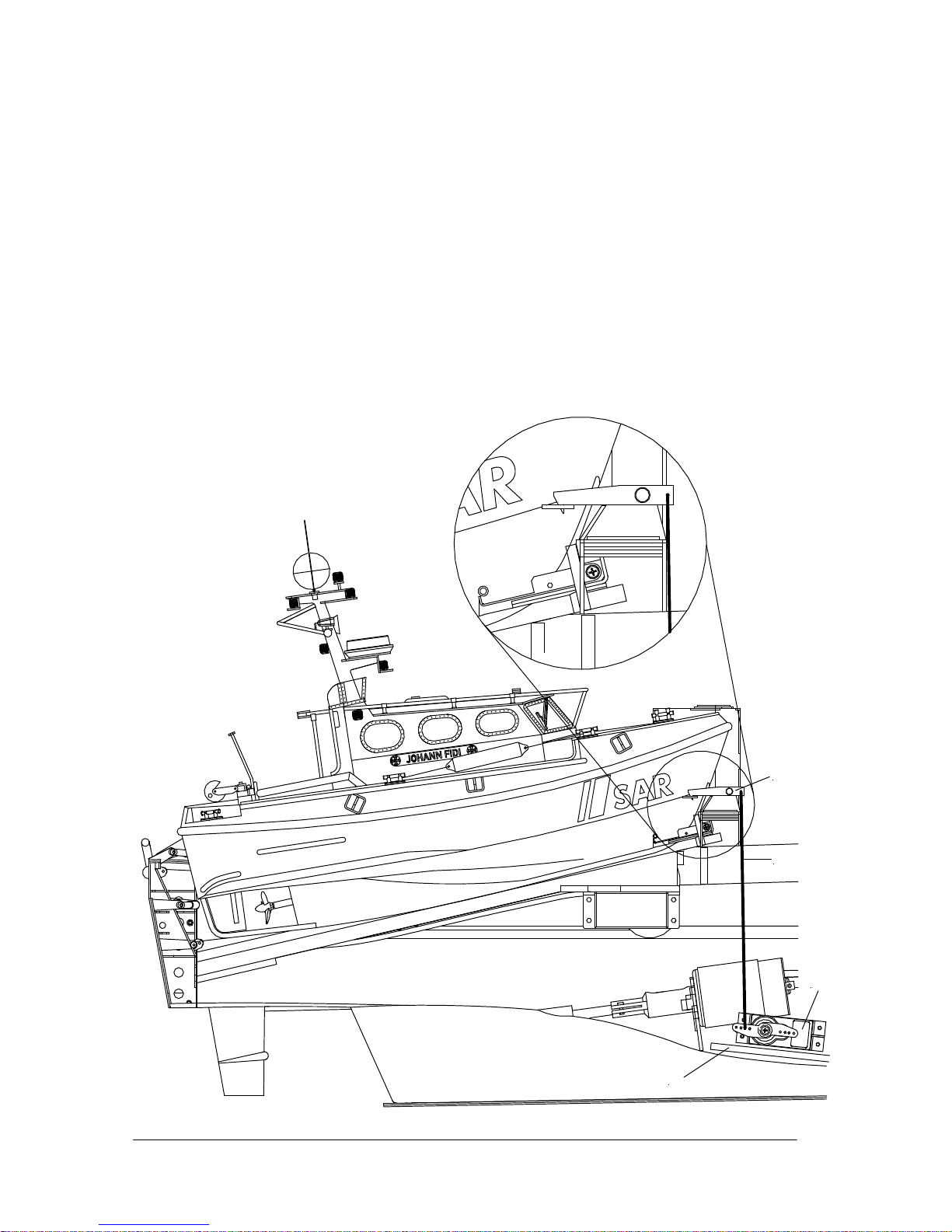
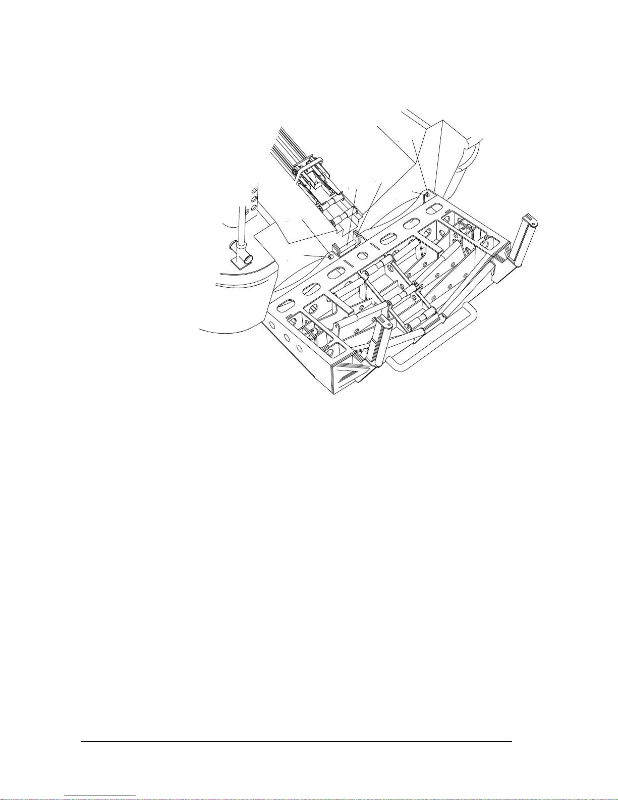
Einbau- und Einstellhinweise zum Tochterbootaufzug
Grundlegende Vorgabe bei der Entwicklung dieses Aufzugsystems war es, dass sowohl das Aussehen als
auch die Funktionsweise des Originalaufzuges so weit wie möglich wiedergegeben werden. Darüber
hinaus sollte es möglich sein, die gesamte Baugruppe mit wenig Aufwand für Wartungszwecke aus dem
Rettungskreuzer zu entfernen. An Stelle der platzraubenden Antriebsspindel kommt bei diesem System
eine Winde zum Einsatz, so dass alle benötigten Komponenten an der Tochterbootwanne befestigt
werden können. Zur Demontage sind dann nur die Verschraubungen der Wanne, die wasserdichte
Verklebung zur Heckwand, sowie die Kabel zur Winde zu lösen, und schon kann der Aufzug komplett mit
der Wanne aus dem Rettungskreuzer herausgenommen werden. Hierdurch wird ein optimaler Zugang zur
Ansteuerung der Ruder und der Heckklappenmechanik gewährleistet.
Funktionsweise
• Das Tochterboot befindet sich auf dem Rettungskreuzer in der Heckwanne und ist nur mit dem
Fanghaken gesichert. In dieser Grundposition haben die Arme des Aufzuges das Tochterboot
freigegeben. Nach dem Öffnen der Heckklappe braucht somit nur der Fanghaken entriegelt werden,
und das Tochterboot rutscht aus der Heckwanne. Deshalb ist auch auf die Leichtgängigkeit der
Laufrollen in der Heckwanne und Heckklappe zu achten.
• Nachdem das Tochterboot die Heckwanne verlassen hat, wird der Schlitten des Aufzuges in die
untere Aufnahmeposition gefahren. Hier senken sich die Arme automatisch ab, so dass das
Tochterboot beim Hineinfahren in die Wanne den Schlitten überfahren kann, ohne hängen zu bleiben.
• Befindet sich das Tochterboot in der Heckwanne, so wird der Aufzug in die obere Position gefahren.
Hierbei heben sich die Fangarme des Schlittens automatisch an und greifen in die Aufnahme am
Page 5
GRAUPNER GmbH & Co. KG D-73230 KIRCHHEIM/TECK GERMANY
Keine Haftung für Druckfehler. Technische Änderungen vorbehalten! #0060384 04/2009
5
Tochterboot. Wenn das Tochterboot nicht optimal zum Aufzug platziert ist, besteht eine hohe
Wahrscheinlichkeit, dass es nicht erfolgreich gefangen wird. Daher ist dieser Vorgang zu üben, damit
Sie die dafür notwendige Position erreichen. TIPP: das Tochterboot mit laufenden Motor
heraufziehen, dabei wird es weiter in die Heckwanne gedrückt und damit besser zentriert. HINWEIS:
es hat sich auch gezeigt, dass der Ø25mm Propeller nicht benötigt wird, daher ist der Hinweis aus der
Anleitung von 2027.100 hinfällig.
• Unmittelbar vor dem Stopp an der oberen Position rastet der Fanghaken ein, während sich zeitgleich
die Fangarme des Schlittens automatisch absenken. Nun kann die Heckklappe geschlossen werden.
HINWEIS: diese Einstellung ist nicht leicht zu finden und muss für jedes Modell, bedingt durch die
Bautoleranzen, separat angepasst werden.
• Der Tiefgang des Modells sollte so eingestellt werden, dass das Tochterboot problemlos in die Wanne
fahren kann. HINWEIS: das Gewicht des Tochterboots beeinflusst den Tiefgang im Heckbereich, bei
der Einstellung des Tiefgangs muss dies also ohne Tochterboot geschehen. Ein stärkeres Eintauchen
des Hecks mit Tochterboot lässt sich deshalb nicht verhindern. Bei den großen Vorbildern ist dies
genauso.
• Sie können auch mit der Einstellung des Öffnungswinkels der Heckklappe das Ausrichten des
Tochterboots zum Kreuzer beeinflussen. Dieser Winkel muss daher auch durch Tests optimiert
werden.
33
182
186
187
Page 6
GRAUPNER GmbH & Co. KG D-73230 KIRCHHEIM/TECK GERMANY
Keine Haftung für Druckfehler. Technische Änderungen vorbehalten! #0060384 04/2009
6
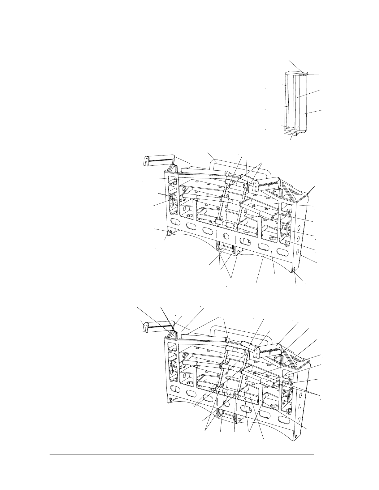
Die Steuerung der Fangarme
Beide Fangarme sind durch einen Bügel verbunden, der seitlich an den Führungsschienen entlang greift.
Dieser Bügel dient der Bewegung der Fangarme und darf keinesfalls entfernt werden. Bedingt durch die
innerhalb der Fangarme liegende U-förmige Feder, werden die Arme permanent angehoben. Das
Absenken in der unteren Position erfolgt dadurch, dass der Fangarmbügel gegen die seitlich befestigten
Anschläge an den Schienen läuft. In der oberen Position ist das Modell so ausgelegt, dass die obere
Querstrebe des Bügels gegen die über dem Schienenende befindliche Abdeckplatte (in querverbauten
Kasten) läuft und so die Fangarme niederdrückt werden. Die Drahtfeder besteht aus nichtrostendem
Federdraht, ein Konservieren zur Rostverhinderung ist nicht nötig.
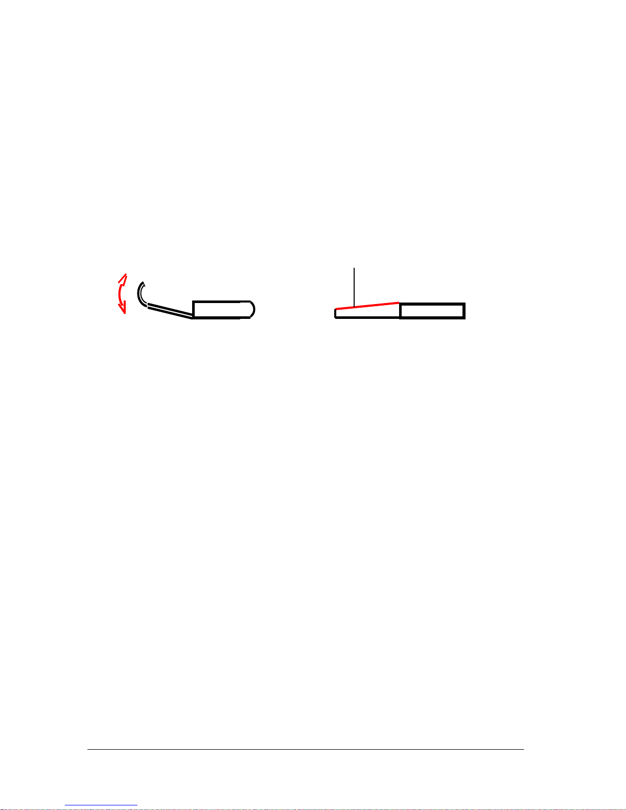
Fangarme einstellen
Als abschließende Arbeit werden jetzt die Fangarme durch Biegen so justiert, dass diese in / hinter die
tochterbootseitige Aufnahme greifen. Eventuell kann es nötig werden, die Breite der Fangarme im Bereich
der Aufnahme am Tochterboot etwas zu verschmälern, was durch Abfeilen zu bewerkstelligen ist.
HINWEIS: durch das häufige Biegen kann das Messingblech brechen, besonders beim Biegen von engen
Radien. Seien Sie deshalb besonders vorsichtig beim Biegen.
Funktion des Fanghakens
Dieser Fanghaken greift unmittelbar vor dem Absenken der Fangarme in die tochterbootseitige Aufnahme,
was durch das Eigengewicht des Hakens geschieht. Es ist darauf zu achten, dass der Haken auf der zum
Tochterboot gerichteten Seite übergewichtig ist, was dadurch erreicht wird, dass diese Seite länger
ausgeführt wird (ca. 2/3 der Hakenlänge). Der Haken muss in seiner Lagerung absolut leichtgängig sein,
dies gilt auch für die Seilführung von Haken zum Hakenservo. Auch darf kein Kabel usw. in den Bereich
der Zugschur gelangen können, da sich sonst der Haken nicht mehr kontrolliert bewegen lässt.
Anbringung der Mitnehmer am Tochterboot
Am Tochterboot wird für den Fanghaken der Haltebügel so angebracht, dass wenn das Boot in der
Wanne liegt, der Bügel waagerecht zum Deck ist. Die Position sollte so gewählt werden, dass der Haken,
wenn er eingehakt ist, ebenfalls waagerecht liegt. Für den Haltestift des Aufzugs (in der Anleitung von
2027.100 Haltebügel für den Aufzug genannt) verwenden Sie als Führungsrohr das Bowdenzug-
Außenrohr (Ø3,2/2,1) im Innenbereich des Rumpfes, stecken Sie dann als eigentlichen Haltestift ein
entsprechend langes Stück vom Bowdenzug-Innenrohr (Ø1,85/0,9) hinein. Dieses ist optimal geeignet,
um eine sichere Fangfunktion zu erreichen und durch diese Flexibilität bricht es nicht ab, wenn Sie mit
dem Tochterboot irgendwo hängen bleiben. Es hat sich herausgestellt, dass das Konzept, wie es in der
Anleitung des Tochterboots beschrieben wird, nicht die gleiche Betriebssicherheit erreicht.
Aufbau der Rollen
Die Rollen werden grundsätzlich mit Bowdenzug-Innenrohr als Achse, ABS-Rohren als Rollen und ABSLaserteile als Lager aufgebaut. Bei bestimmtem Rollen, besonders bei stark belasteten und vertikal
stehenden Rollen sollten Sie in der Achse ein Stück 0,8mm Stahldraht als Innenachse verwenden. Die
Enden des Stahldrahts sollten ca. 4mm überstehen und dann umgebogen werden. Auf diese Art können
Sie die Achse gegen Herausfallen sichern. TIPP: es besteht auch die Möglichkeit, den Draht mittig zu
trennen, die Ende umzubiegen und dann je ein Teil einzustecken und zu verkleben.
Bei Achsen, die weniger belastet werden, reicht es aus, das Bowdenzug-Innenrohr etwas länger zu
lassen, die Lager aufzustecken und das Rohr sauber abzuschneiden. Wichtig ist es, dass das Rohr keine
Quetschungen an den Enden aufweist. Daher sollten Sie es nicht mit einem Seitenschneider oder Schere
kürzen. Wenn die Enden nicht gut in den Lager liegen besteht die Möglichkeit, dass bei Belastung die
Rolle aus den Lagern gedrückt wird.
Die s e Kante evtl. a n passen
Page 7

GRAUPNER GmbH & Co. KG D-73230 KIRCHHEIM/TECK GERMANY
Keine Haftung für Druckfehler. Technische Änderungen vorbehalten! #0060384 04/2009
7
Lackierung
• Fragen Sie Ihren Modellbauhändler oder den Farbenfachhändler nach den opti malen Farben.
• Beachten Sie die Verarbeitungshinweise der Lacke.
• Verwenden Sie NUR Farben vom gleichen Hersteller und Lacktyp, da sonst die Farben miteinander
reagieren können und sich wieder ablösen bzw. Blasen werfen. Seien Sie besonders vorsichtig bei
der Kombination von Sprühdosenfarben und Streichfarben, probieren Sie immer an Reststücken, ob
die Farben miteinander reagieren.
• Um eine gute Haftung der Farben zu erreichen, schleifen Sie mit feinem Nassschleifpapier (Körnung
600 bis 800) die Oberflächen an. Entfetten Sie danach die Oberfläche mit einem nicht nachfettenden
Spülmittel oder Spiritus. Bis zur Lackierung sollte die Oberfläche möglichst nicht mehr angefasst
werden, da der Hautschweiß wieder neues Fett auf die Oberfläche bringt.
• Kleben Sie beim Spritzen der Farbe alle Bereiche, die nicht lackiert werden sollen, komplett ab.
Dichten Sie alle Öffnungen ab, da der feine Farbnebel in alle noch so kleine Öffnungen kommt.
• Um feine und gerade Kanten abkleben zu können, sollten Sie ein möglichst schmales Klebeband
einsetzen, z.B. ein Zierlinienklebeband. Kleben Sie es ohne Zug sauber und genau auf, danach
können Sie die verbliebenen Flächen mit Malerkrepp und Papier bzw. Folie abdecken.
• Überlegen Sie vor Baubeginn wie und in welcher Reihenfolge Sie das Modell lackieren wollen oder
halten Sie sich an die empfohlene Reihenfolge. Bestimmte Stellen lassen sich später nur schwer oder
gar nicht mehr lackieren.
• TIPP: um Kleinteile leichter lackieren zu können, sollten Sie diese an der Stelle der späteren
Klebeverbindung mit doppelseitigem Klebeband auf einem Holzstab oder Vergleichbarem montieren.
So können Sie das komplette Teil auf einmal lackieren.
Farbgebung
Damit die richtigen Farbtöne leichter ausgewählt werden können, werden nur die RAL-Farbtöne
angegeben. Mit diesen Angaben können Sie sich in jedem Farben- oder Modellbaufachgeschäft die
Farben zusammenstellen lassen. Teilen Sie dem Fachberater im Farbenfachgeschäft den vorgesehenen
Einsatzzweck der Farben mit, damit er den richtigen Lacktyp auswählt. Wir empfehlen einen
Kunstharzlack. Es darf kein Nitrolack verwendet werden!
Überwasserschiff, Aufbau, Schanzkleid, Deckkästen, Mast, Kleinteile,
Schutzbügel, Reling, Suchscheinwerfer, Sockel von Löschmonitor RAL 9016
Unterwasserschiff RAL 3009
Decks, Heckwanne, Poller, Kleinteile, Treppenstufen RAL 6001
Fahrstand, Schanzkleidinnenseiten RAL 6019
Tagesleuchtfarbe für Aufbau und Mast RAL 3024
Fenderleiste, Scheinwerfer, Lautsprecher, Anker RAL 9006
Schanzkleidfender, Rettungswesten RAL 2003
Kugelfender RAL 2002
Löschmonitor RAL 3000
Oberer Bereich vom Auspuffverkleidung, Teile vom Schutzbügel,
Bugflaggenstock, oberer Bereich der Sprungtuchmasten RAL 9005
Zuordnung Dachkennzeichnung zum Schiffsnamen
Hermann Rudolf Meyer DBAC
Hans Hackmack DBAT
Bernhard Gruben DBBS
Theo Fischer DBBR
Pflege und Wartung
• Säubern Sie das Modell nach jedem Gebrauch. Entfernen Sie evtl. eingedrungenes Wasser. Sollte
Wasser in die RC-Komponenten gedrungen sein, legen Sie diese trocken und schicken Sie die RCKomponenten zur Kontrolle an die zuständige GRAUPNER Servicestelle ein.
• Säubern Sie das Modell und den Sender nur mit geeigneten Reinigungsmitteln. Geeignet ist ein
fusselfreies Tuch. Verwenden Sie niemals chemische Reiniger, Lösungsmittel, Reinigungsbenzin,
Spiritus oder ähnliches.
• Schmieren Sie die Antriebswellen nach Ende des Betriebs mit einem kleinen Tropfen Öl an den
Page 8
GRAUPNER GmbH & Co. KG D-73230 KIRCHHEIM/TECK GERMANY
Keine Haftung für Druckfehler. Technische Änderungen vorbehalten! #0060384 04/2009
8
Lagern ab. Auch die äußeren Wellenlager bei den Propellern müssen geschmiert werden. Verwenden
Sie zum Schmieren der Antriebe nur Öl, welches das Wasser nicht gefährdet bzw. verschmutzt (z.B.
Best.-Nr. 206). Nach Ende der Fahrsaison sollten die Wellen demontiert werden und mit
wasserneutralem Fett (z.B. Best.-Nr. 570) neu abgeschmiert werden.
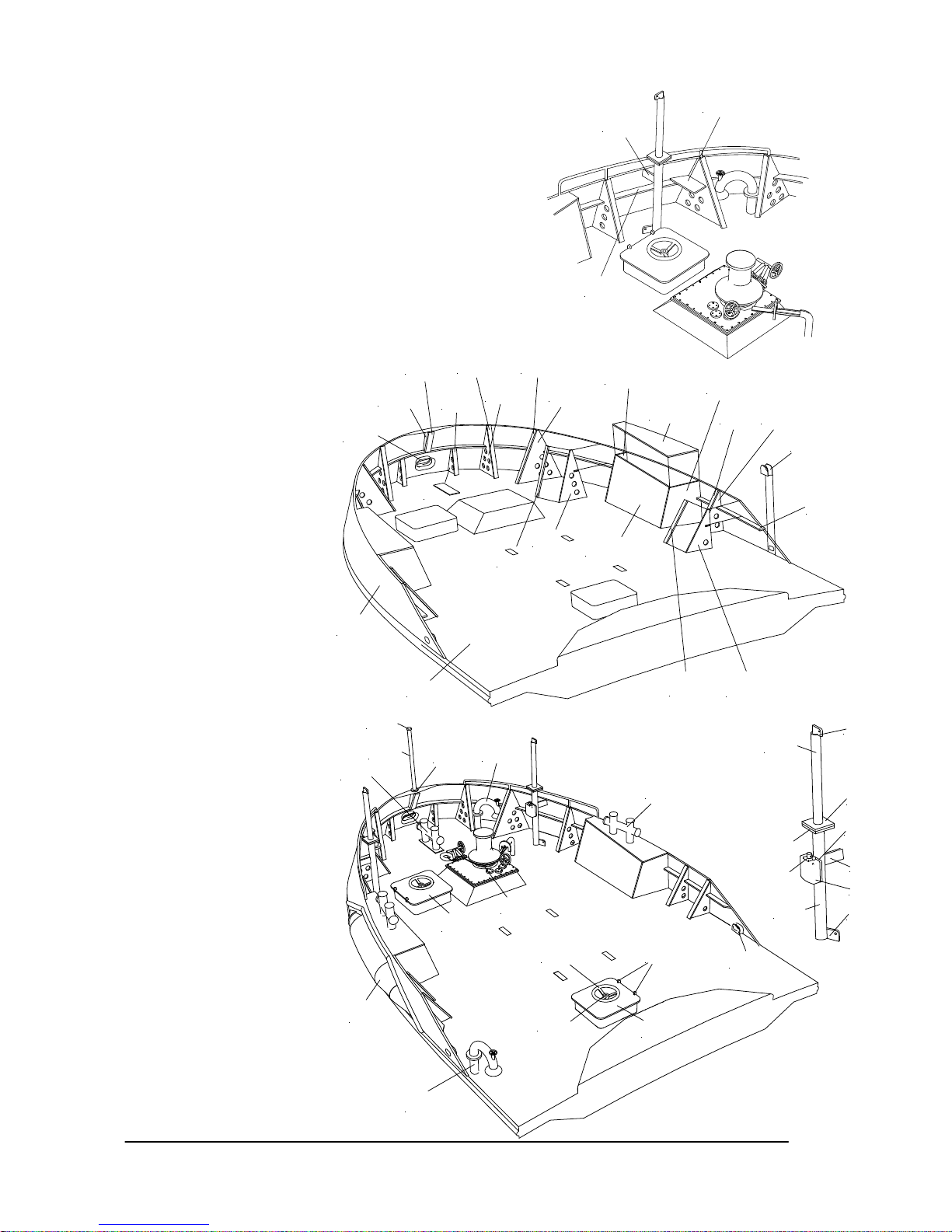
Montageanleitung
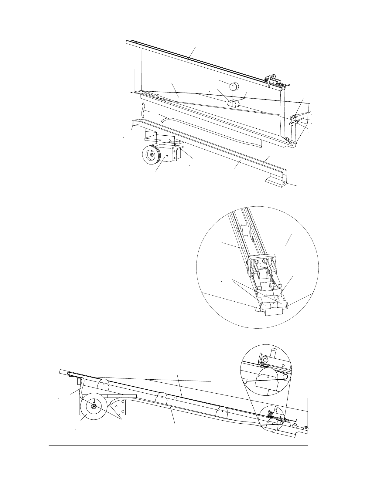
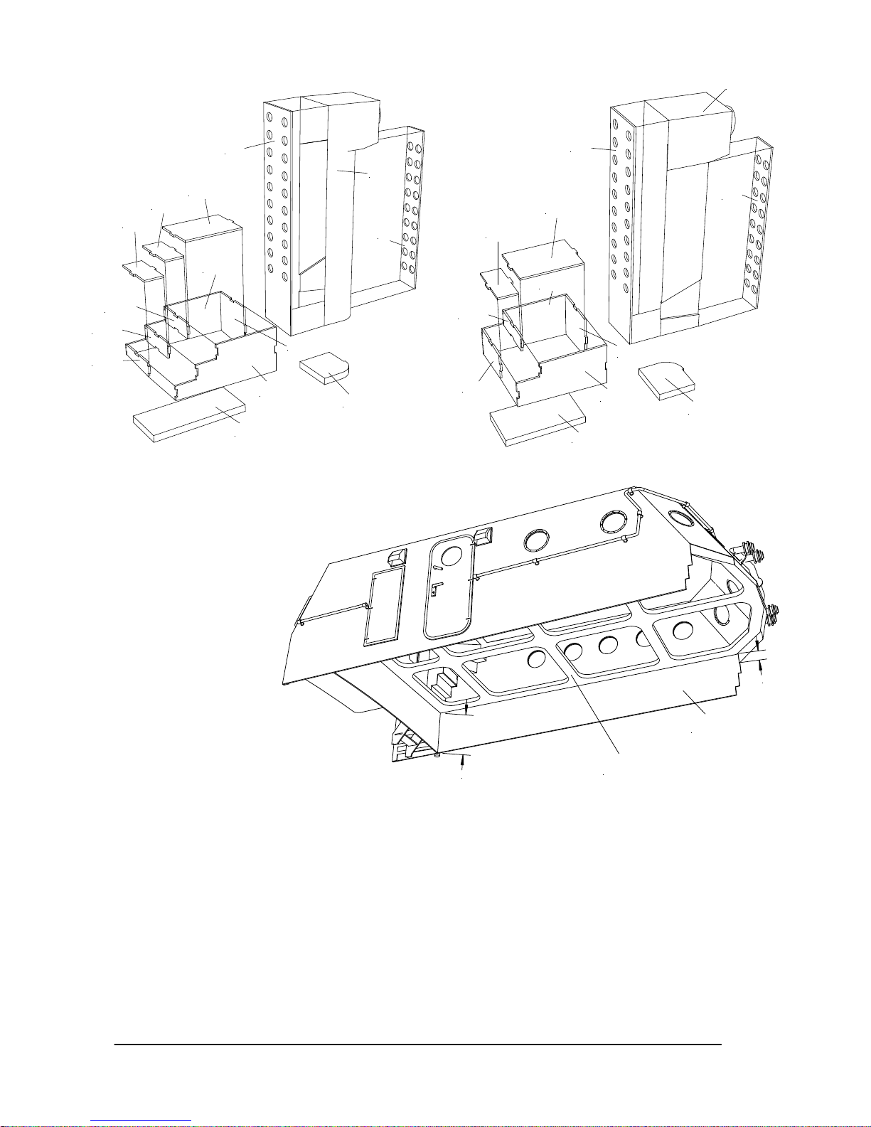
• Doppeln Sie die Einzelteile vom Schiffsständer (Pos. 1 + 2 + 3) auf und verkleben diese dann.
• Kleben Sie unten an den Rumpf (Pos. 4) die jeweils aufgedoppelte Kielhacke (Pos. 5) und den
Schottelpumpjet (Pos. 6).
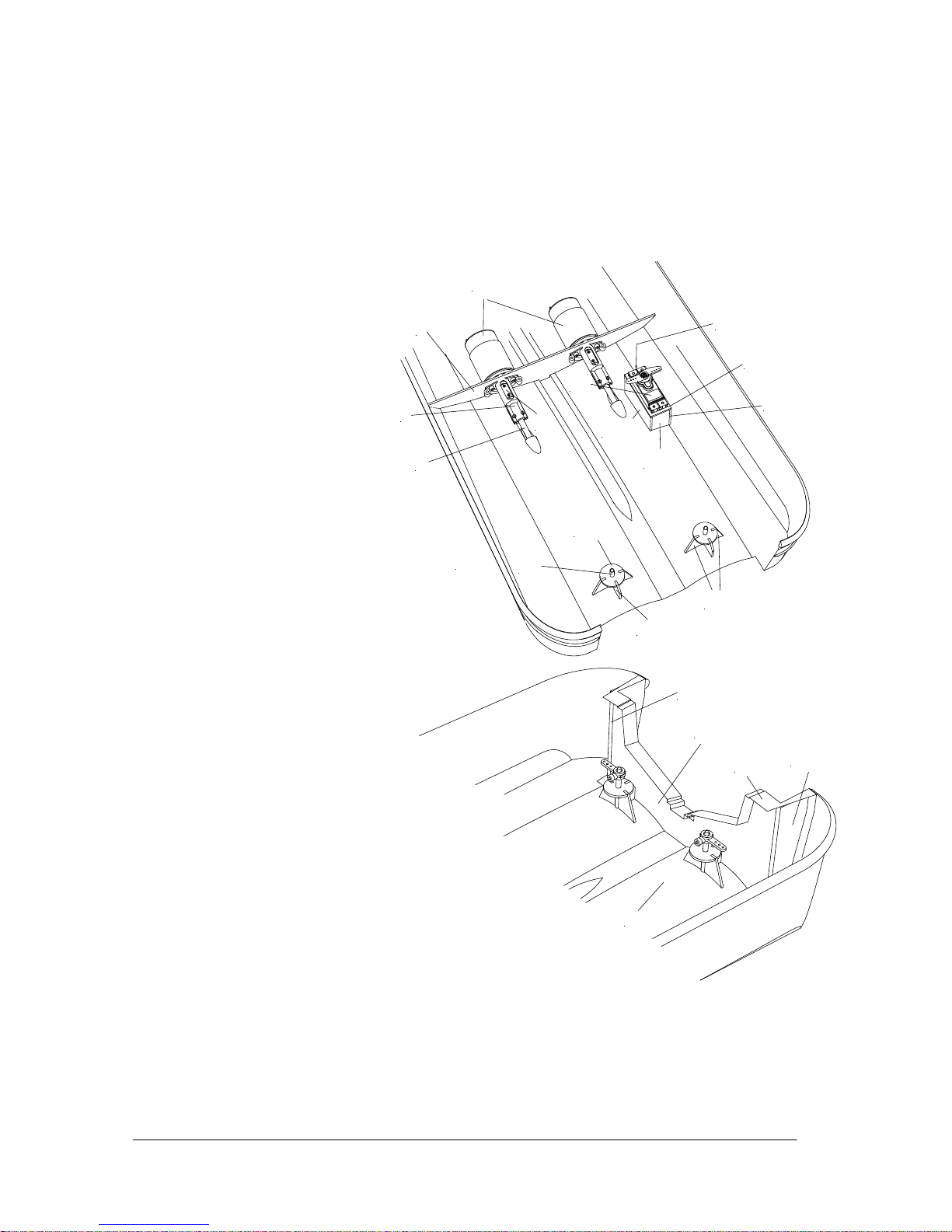
• Montieren Sie an jedes
Stevenrohr (Pos. 7) je einen der
Motorträger (Pos. 8). Kleben Sie
dann die Motorträger in den Halter
der Motorträger (Pos. 9). Sie
müssen auf der Rückseite bündig
und gerade zur Holzoberfläche
liegen.
• Montieren Sie an die Motoren
(Pos. 10) die Wellenkupplungen
(Pos. 11). Montieren Sie dann die
Motoren an die Motorträger. Es ist
empfehlenswert, jetzt auch die
Entstörkondensatoren und die
Anschlusskabel anzulöten.
• Stecken Sie die Motoreinheit in
den Rumpf und richten Sie diese
im Rumpf aus. Fixieren Sie dann
die Einheit mit Sekundenkleber im
Rumpf und kleben Sie die dann
sicher mit UHU acrylit fest. Kleben
Sie einen der vorher angepassten
Wellenabstützungen (Pos. 12)
schräg an Rumpf fest. Bei der
gegenüberliegenden wird die
Wellendurchführung (Hülse)
entfernt und dann an die Hülse von
der anderen angeklebt. Die spätere
Wellenabstützung soll eine V-Form
erhalten.
• Montieren Sie die beiden Propeller
(Pos. 13 + 14) an den Stevenrohren.
• Kleben Sie die Heckwand (Pos. 15)
im Rumpf ein. Achten Sie dabei
darauf, dass die Seitenwände gerade
an den Ausschnitt im Rumpf geklebt
werden. Nehmen Sie auch die
Heckklappe zu Kontrolle.
• Kleben Sie dann die
Heckwandverstärkungen (Pos. 16)
innen an die Heckwand.
• Längen Sie die beiden Ruderkoker
(Pos. 17) und die Ruderwellen (Pos.
18) ab. Schneiden Sie dann die
Ruderblatthälften (Pos. 19) aus, schleifen diese plan, arbeiten die Öffnungen für die Ruderwelle ein und
kleben dann die Wellen ein. Es ist empfehlenswert, die Wellen vorher flach anzuschleifen, damit diese
besser im Ruder gehalten werden. Kleben Sie die andere Ruderblatthälfte auf. Kleben Sie den
Ruderkokerhalter (Pos. 20) aus den vier Teilen zusammen. Kleben Sie dann den Ruderkoker in den
Halter. Oben sollte der Koker ca. 10mm herausstehen. Stecken Sie dann die Halter in den Rumpf,
stecken die Ruder in die Koker, richten diese aus und verkleben diese im Rumpf. Montieren Sie die
Ruderhebel (Pos. 21) zusammen und schrauben diese auf die Wellen.
• Montieren Sie die Gestängeanschlüsse (Pos. 22) an die Ruderhebel (vorher die Bohrungen auf Ø2mm
4
7
8
9
10
11
20.1
20.2
20.3
17
24.3
24.4
24.2
24.1
24.5
25
4
16.1
16.2
16.2
15
Page 9
GRAUPNER GmbH & Co. KG D-73230 KIRCHHEIM/TECK GERMANY
No liability for printing errors. Technnical modifications reserved. #0060384 04/2009
9
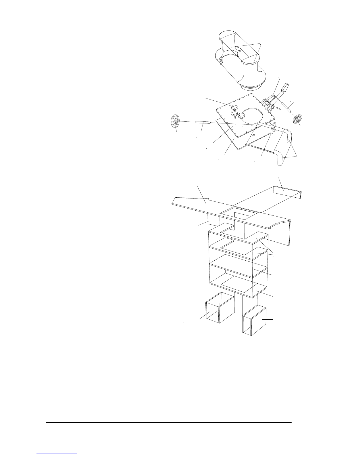
aufbohren). Fertigen Sie das quer verlaufende Rudergestänge (Pos. 23) an und montieren Sie es an den
Gestängeanschlüssen.
• Kleben Sie den Ruderservohalter (Pos. 24) zusammen. Achten Sie dabei auf die richtigen Positionen der
Seitenteile. Montieren Sie an das Ruderservo (Pos. 25) einen Gestängeanschluss (Pos. 22) und
schrauben das Servo in den Halter. Längen Sie das längs verlaufende Rudergestänge (Pos. 26) ab und
montieren es.
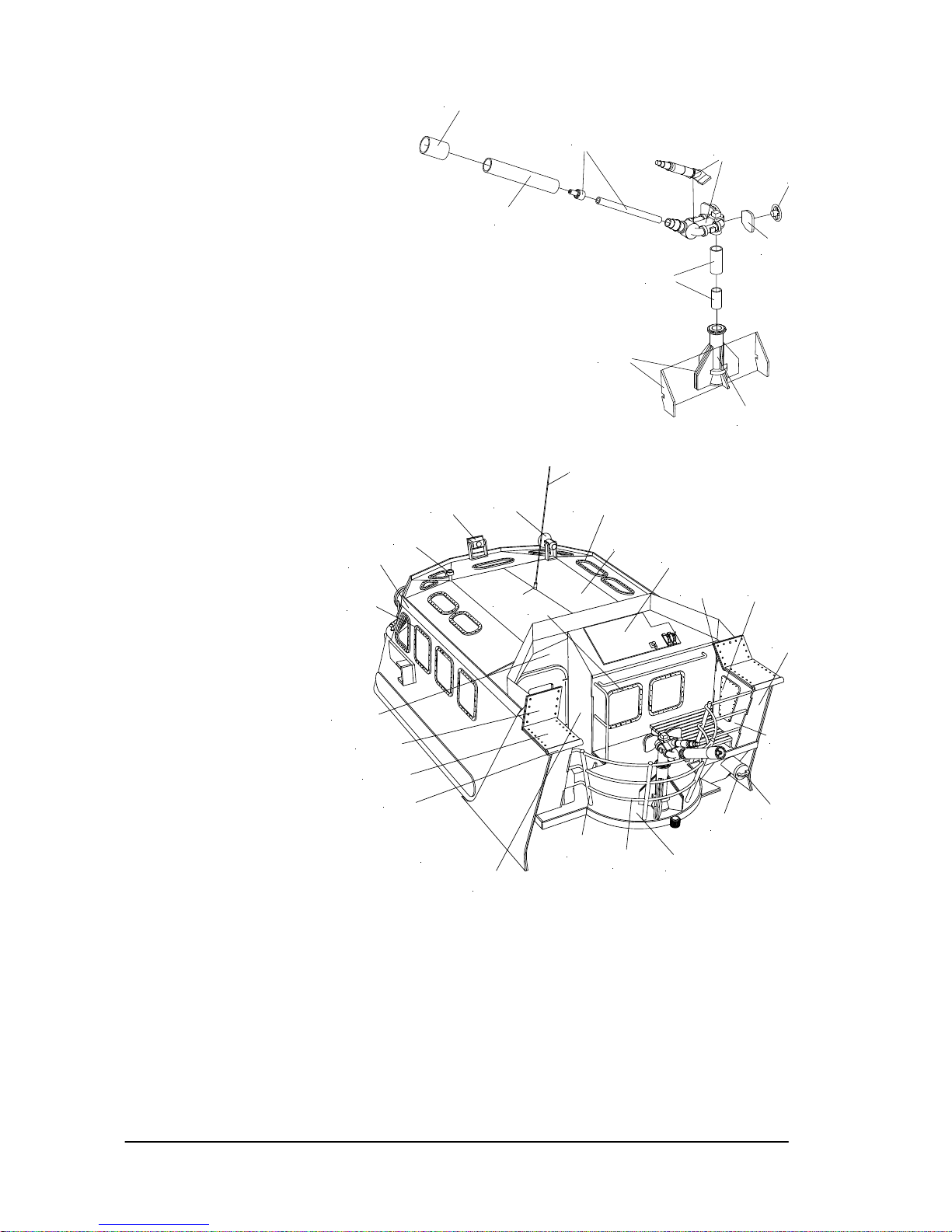
• Kleben Sie unter die Wasserpumpe für den Schottelpumpjet und den Löschmonitor (Pos. 27)
doppelseitiges Klebeband. Löten Sie die Anschlusskabel und den Entstörkondensator an die Pumpen.
Bohren Sie zwei Ø4mm Löcher für die Anschlussstutzen (Pos. 28) und den Ansaugstutzen für den
Löschmonitor (Pos. 29) im Kiel vom Rumpf. Fertigen Sie dann die Anschluss- und den Ansaugstutzen
an und kleben diese in den Rumpf. Stecken Sie die Silikonschläuche (Pos. 30) auf die Stutzen an eine
der Pumpe, legen die Einheit in den Rumpf und stecken die Schläuche auf die Anschlussstutzen. Kleben
Sie dann die Pumpe im Rumpf fest. Das gleiche erfolgt mit der Pumpe für den Löschmonitor. Hier
kommt das lange Stück vom Schlauch (Pos.31) auf den langen Stutzen an der Pumpe. TIPP: es ist
empfehlenswert, ein Stück vom Alurohr aus dem die Stutzen gefertigt worden sind, eine Verbindung in
den Schlauch zum Löschmonitor zu stecken, dann können Sie zu Wartungsarbeiten diesen Schlauch
leichter trennen.
• Fertigen Sie die Ankerklüse (Pos. 32) an und kleben diese wasserdicht in den Rumpf.
• Kleben Sie die Auflagefläche für das Hakenservo (Pos. 33) in den Rumpf. Diese Fläche ist ein Stück aus
dem Innenrahmen für den Aufbau (Pos. 217).
• Schrägen Sie die Auflagefläche der Fahrakkus (Pos. 34) passend zum Rumpf an und kleben die dann in
den Rumpf. HINWEIS: die Auflagefläche sollte möglichst optimal anliegen.
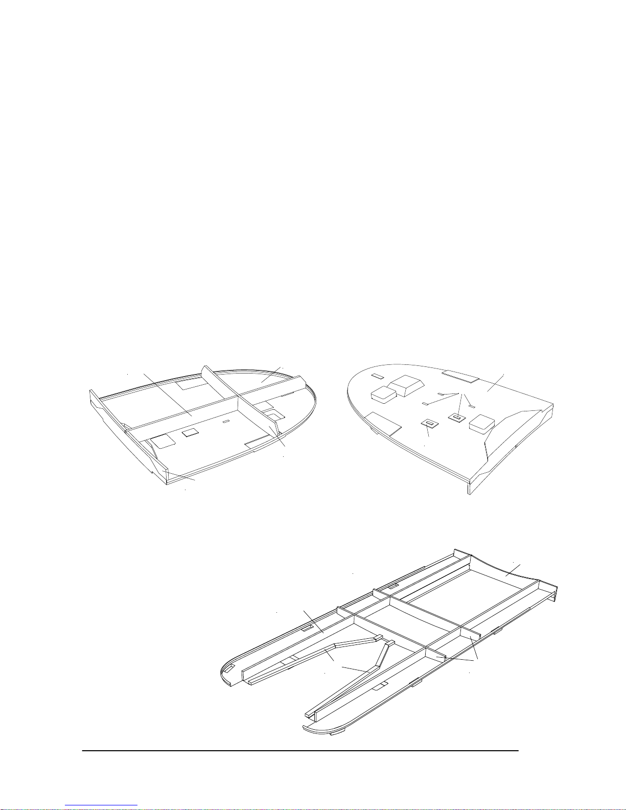
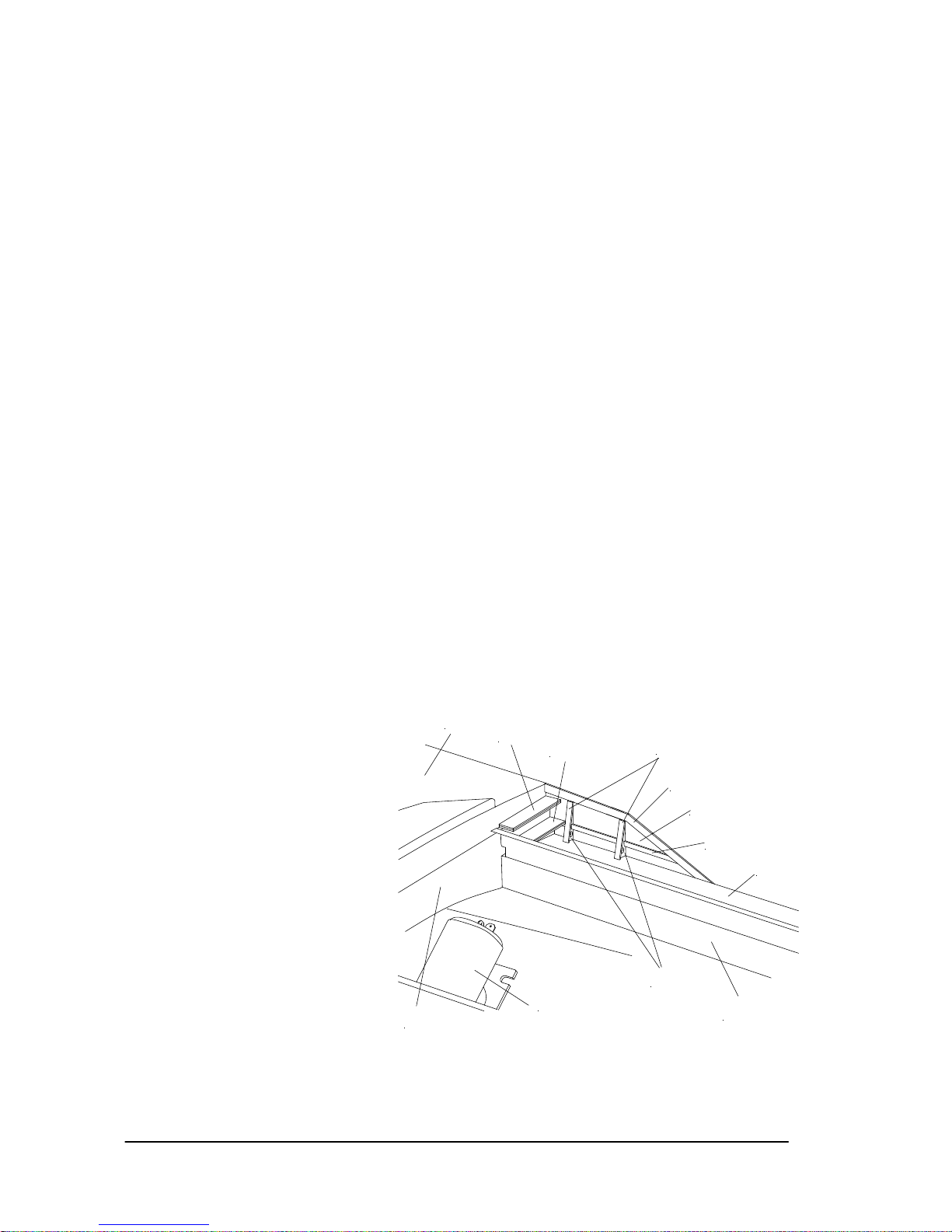
• Kleben Sie unter das Backdeck (Pos. 35) die drei Verstärkungen (Pos. 36). Arbeiten Sie die Langlöcher
im Deck rechteckig aus. Fertigen Sie dann die Oberlichter (Pos. 37) an. Diese werden aufgedoppelt, so
dass das obere Rechteck genau in das vorher im Deck ausgearbeitete Rechteck passt. Das untere
Rechteck dient zum späteren Verkleben unten im Deck. Kleben Sie die Oberlichter erst nach dem
Lackieren unter das Deck.
• Kleben Sie das Backdeck in den Rumpf. Achten Sie beim Verkleben darauf, dass die Scheuerleisten
bündig anliegen und das Deck nicht schief verklebt wird.
• Kleben Sie unter das Hauptdeck (Pos. 38) die vier Verstärkungen (Pos. 39). Die vordere
Querverstärkung liegt
genau in der oberen
Treppenstufe. Kleben
Sie dann das
Hauptdeck in den
Rumpf. Auch hier
müssen Sie darauf
achten, dass die
Scheuerleisten sauber
anliegen und auch die
Verbindung Heckwand
zum Deck gut anliegt.
HINWEIS: achten Sie
beim Verkleben
unbedingt darauf, dass
der Aufbau (Pos. 217)
passt. Hier ist
besonders auf den
Höhenunterschied der
35
37
37
36.1
35
36.3
36.2
39.3
40
39.1
38
39.2
Page 10
GRAUPNER GmbH & Co. KG D-73230 KIRCHHEIM/TECK GERMANY
No liability for printing errors. Technnical modifications reserved. #0060384 04/2009
10
beiden Decks zu
achten.
• Längen Sie aus der
Kiefernleiste die
Verstärkung für die
Heckwanne (Pos.
40) ab und kleben
diese unter die
Auflagefläche für die
Heckwanne unter
dem Deck.
• Schneiden Sie die
unteren vier Stücke
der Scheuerleisten
(Pos. 41) aus und
kleben diese auf den
Rumpf. HINWEIS:
bei den gebogenen
Stücken sollen die
schrägen Flächen in
Richtung der
Heckklappen zeigen.
Danach folgt die
Sprayrail (Pos. 42)
und die
Verlängerung der oberen Scheuerleiste (Pos. 43).
• Schneiden Sie die Heckwanne (Pos. 44) aus und
passen Sie sauber in den Rumpf ein. Kleben Sie
dann den Verstärkungsrahmen (Pos. 45) unten an
die Wanne. Fertigen Sie die beiden Seilführungen
(Pos. 46) aus dem Messingrohr an und kleben
diese in die Wanne. HINWEIS: die Seilführungen
müssen sehr sauber gebogen und die Enden so
bearbeitet werden, dass keine scharfe Stelle mehr
vorhanden ist.
• Kleben Sie an eine Seite der Rollenhalter (Pos.
47) eine Rollenachse (Pos. 48). Stecken Sie dann
eine Rolle (Pos. 49) auf und stecken den zweiten
Rollenhalter auf. Kleben Sie dann die Einheiten in
die Heckwanne.
• Kleben Sie den Tochterbootaufzug (Pos. 50) mit
Sekundenkleber in die Heckwanne. HINWEIS:
sichern Sie mit einem Tropfen Sekundenkleber
auch die Feder im Schlitten gegen Herausfallen.
• Kleben Sie mit doppelseitigem Klebeband die
Segelwinde (Pos. 51) an den
47
50
57
56
54
53
45.1
45.2
45.4
51
46
45.5
45.3
48
49
44
46
46
52
52
51
44
50
56
57
Page 11
GRAUPNER GmbH & Co. KG D-73230 KIRCHHEIM/TECK GERMANY
No liability for printing errors. Technnical modifications reserved. #0060384 04/2009
11
Verstärkungsrahmen. HINWEIS: achten Sie darauf, dass die Seiltrommel passend zu den Seilführungen
sitzt.
• Fädeln Sie über Kreuz das Zugseil (Pos. 52) in die Bohrungen im Schlitten
(noch nicht verkleben). Führen Sie dann das Seil um die äußeren
Messingstäbe und fädeln das Seil in die Seilführungen ein. Fahren Sie dann
die Segelwinde an eine der Endpositionen, schieben den Schlitten an die der
Seiltrommel entsprechende Endstellung und fädeln dann das Seil in die
Trommel ein. Wickeln Sie dann das noch freie Seilende mindestens fünfmal
auf die andere Trommel (auf die Abwickeldrehrichtung achten). Sichern Sie
dann die Seilenden mit der Halteschraube der Seiltrommel. Drehen Sie per
Hand an der Seiltrommel, hierbei merken Sie sofort, ob die Aus- und
Abwickelrichtungen passen. Stellen Sie dann mit dem Einstellpoti auf der
Segelwinde den kleinsten Wickelweg ein. Schließen Sie die Fernsteuerung
an und testen Sie die Endstellungen. Drehen Sie solange am Poti bis Sie die
Endstellungen fast erreicht haben, die Feineinstellung erfolgt dann über die
Servowegbegrenzung am Sender. Achten Sie darauf, dass die
Endstellungen wirklich
angefahren werden, aber
auch nicht darüber.
Geringe Toleranzen
werden aber über den
Schaumstoff im
doppelseitigen Klebeband
ausgeglichen. Wenn dann
alles passt, können Sie das
Zugseil mit einem Tropfen
Sekundenkleber im
Schlitten sichern.
• Stecken Sie an je einen
Rollenhalter (Pos. 53) das
Rollendrehlager (Pos. 54)
und in dieses die
Rollenachse (Pos. 55).
Fertigen Sie die Rolle (Pos.
56) an und kleben den
Außenring (Pos. 57) außen
an die Rollen. Stecken
dann die Rolle auf das
Lager und stecken den
anderen
Rollenhalter auf.
Biegen Sie dann
die überstehenden
Enden von der
Rollenachse um.
Achten Sie darauf,
dass die Rollen
sich noch
leichtgängig
drehen lassen.
Kleben Sie dann
die Einheit in die
Heckwanne.
• Jetzt können Sie
die Heckklappe mit
den acht
Befestigungsschra
uben (Pos. 58)
montieren.
WICHTIG: für den
späteren
Fahrbetrieb
70
64
65.7
65.2
65.3
65.4
65.5
65.8
68
65.1
65.9
65.6
64
69
63
66
67
67
67
71
101
81.2
81.1
86
91
96
103
104.2
104.1
102.2
102.3
102.4
100+99
97
92
95
94
88
90+89
105
108+107
83
84
85
59.2
59.4
59.3
59.6
59.5
59.1
60
62
Page 12
GRAUPNER GmbH & Co. KG D-73230 KIRCHHEIM/TECK GERMANY
No liability for printing errors. Technnical modifications reserved. #0060384 04/2009
12
müssen Sie die Auflagefläche zur Heckwand mit einem schmalen Streifen (ca. 3mm) doppelseitigen
Klebeband (z.B. Teppichklebeband) gegen Wassereinbruch sichern. Es empfiehlt sich auch außen mit
Klebeband den Übergang zu sichern. HINWEIS: durch die Verwirbelungen zwischen Heckklappe und
Heckwand zieht das Wasser auch über die Wasserlini e.
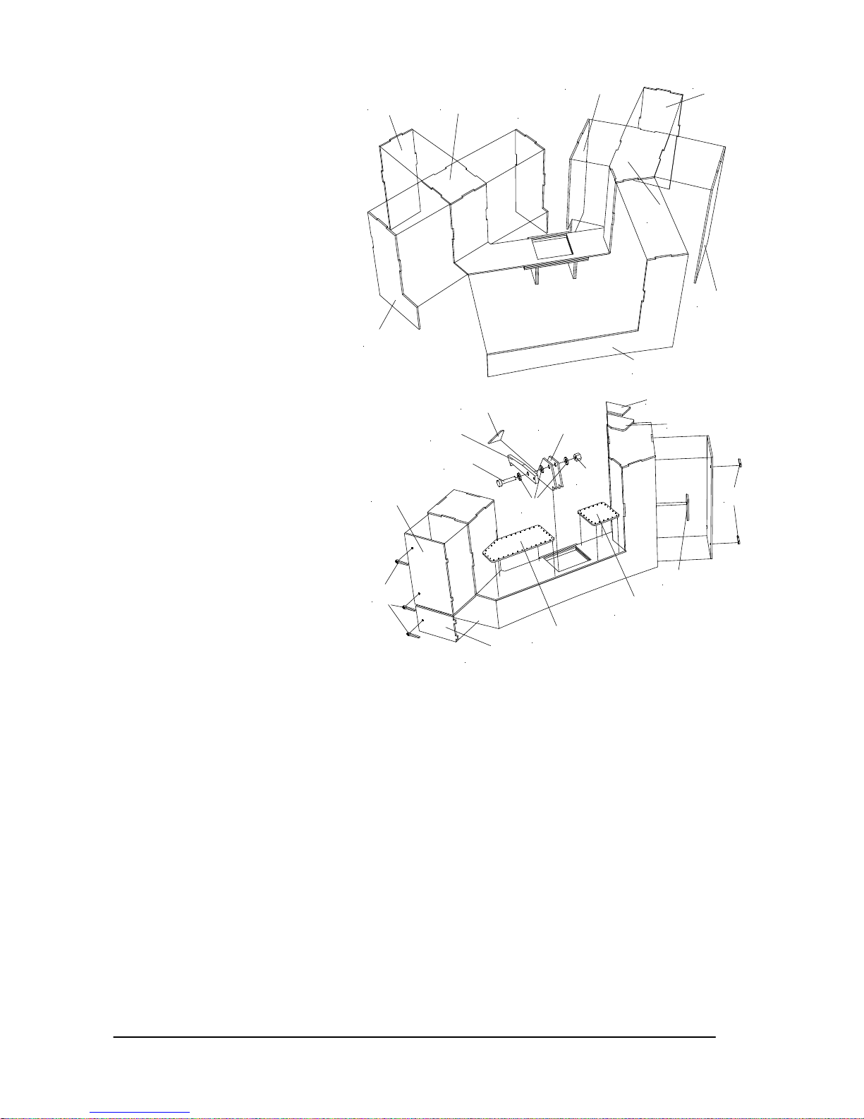
• Das Aufbauschema
der anderen Rollen
wird auch bei den
beiden seitlichen
Führungsrollen
angewendet. Diese
werden aus den
Pos. 59 bis 62
aufgebaut.
HINWEIS: achten
Sie darauf, dass
genügend Abstand
zwischen den
Rollen ist, damit
das Tochterboot
leicht aus der
Wanne rutschen
kann.
• Schneiden Sie die
Heckklappe (Pos.
63) grob aus.
HINWEIS: lassen
Sie ca. 3mm
Überstand übrig,
diese wird erst mit
dem eingesetzten
Innenrahmen
abgeschliffen.
Schneiden Sie die Bereiche, wo die Flutschlitze der Heckverkleidung sind, ebenfalls aus. Kleben Sie die
beiden Seitenwandverstärkungen (Pos. 64) in die Heckklappe.
• Bauen Sie das Innenspantgerüst (Pos. 64) zusammen. Passen Sie das Gerüst soweit an, dass es leicht
in die Heckklappe passt. Schrauben Sie die beiden Gestängeanschlüsse (Pos. 66) in das Gerüst.
Kleben Sie jetzt das Gerüst in die Heckklappe. Kleben Sie dann die Scharnierrohre (Pos. 67) in das
Gerüst. WICHTIG: achten Sie darauf, dass alle in einer Achse liegen.
• Kleben Sie die Abdeckungen (Pos. 68) oben auf die Heckklappe.
• Jetzt wird die Heckklappe erst endgültig passend bearbeitet. Schleifen Sie unten an der Heckklappe im
Bereich der Scharniere im Innenbereich einen Radius an. Dieser Radius wird benötigt, damit die
Heckklappe aufklappen kann.
• Kleben Sie die Mittelscharniere (Pos. 69) zusammen. Kleben Sie dann das Mittelscharnierrohr (Pos. 71)
ein. Achten Sie daraus, dass die Scharniere genau zueinander angeordnet sind.
• Bohren Sie für die Außenscharnierrohre (Pos. 72) Bohrungen. WICHTIG: achten Sie hier genau auf die
richtige Position der Bohrlöcher, da sonst die Heckklappe schief im der Heckverkleidung sitzt.
Übertragen Sie die Maße der Position von der Heckklappe auf die Seitenwand. Sollten Sie die Position
nicht genau erreicht haben, verschließen Sie die Bohrung mit UHU acrylit und bohren neu. Kleben Sie
dann die Rohre ein.
• HINWEIS: das Konzept mit den Scharnierstiften aus Bowdenzugrohr ermöglicht die leichte Demontage
der Heckklappe, indem Sie den Stift mit einer Zange herausziehen und später dann wieder einstecken.
Deshalb muss auch immer ein Teil vom Bowdenzugrohr herausstehen, damit es durch die Wölbung der
Wellentunnel gesichert wird und Sie genügend Material haben, um es herausziehen zu können.
• Stecken Sie das Mittelscharnier in die Heckklappe und sichern es mit dem Scharnierstift (Pos. 73).
Halten Sie die Heckklappe in die Heckwand und stecken die beiden äußeren Scharnierstifte (Pos. 74)
ein. Wenn die Heckklappe sich sauber öffnen und schließen lässt, können Sie das Mittelscharnier an die
Heckwand kleben. Bei der noch montierten Heckklappe ergibt sich automatisch die richtige P osition.
• Übertragen Sie die Bohrungen für das Führungsrohr (Pos. 75), indem Sie ein kurzes Stück
Bowdenzugrohr in die Gestängeanschlüsse stecken und die Heckklappe dann schließen. Kleben Sie
dann die Führungsrohe ein. Stecken Sie die Bowdenzüge (Pos. 76) in die Rohre und schließen sie an
die Gestängeanschlüsse an.
• Schrauben Sie die Servohebelverlängerungen (Pos. 77) an die Servohebel mit den
67
70
71
67
73
74
Page 13
GRAUPNER GmbH & Co. KG D-73230 KIRCHHEIM/TECK GERMANY
No liability for printing errors. Technnical modifications reserved. #0060384 04/2009
13
Befestigungsschrauben (Pos. 78) an. Schleifen Sie die überstehenden Enden der Schrauben plan.
Schrauben Sie dann je einen Gestängeanschluss (Pos. 79) an den Hebel. WICHTIG: stellen Sie beide
Servos auf die gleiche Hebelstellung ein, damit sie beim Bewegen keine unterschiedlichen Wege fahren,
hierbei könnte die Heckklappe verkanten und klemmen. Führen Sie dann die Bowdenzüge in die
Gestängeanschlüsse und kleben die Heckklappenservos (Pos. 80) mit doppelseitigem Klebeband im
Rumpf fest. HINWEIS: das doppelseitige Klebeband mit der Mossgummischicht dient zum Ausgleich der
verbleibenden Toleranzen, daher sollten die Servo nicht fest montiert werden.
• Bauen Sie die mittleren Führungsrollen aus den Pos. 81 bis 85 gen auso zusammen, wie die baugleichen
Rolle in der Heckwanne.
• HINWEIS: die Führungsrollenhalter für die großen Rollen der Hecklappe sind länger ausgelasert. Sie
müssen durch den Modellbauer angepasst werden, da sie auch dem Winkel der Rollen entsprechend
abgeknickt werden müssen. Daher empfiehlt es sich die Rolle zuerst fertig zu stellen, die Halter an die
Achsen zu kleben und dann die Halter soweit zu kürzen und abzuknicken, dass diese die richtige
Position für die Rolle erreichen. Das Bauschema entspricht den schon hergestellten Führungsrollen.
HINWEIS: achten Sie auch darauf, dass bei geschlossener Heckklappe das Tochterboot noch genügend
Platz hat. Die unteren seitlichen Rollen (Pos. 86 bis 90) sind in der Zeichnung dargestellt, sollten aber
nicht verwendet werden. Sie werden für die Funktion der Tochterbootabnahme nicht benötigt. WICHTIG:
außerdem müssen die so angebracht werden, damit sie nicht über Pos. 65.7 überstehen, da sich sonst
die Heckklappe nicht mehr schließen lässt.
• Biegen Sie die Heckklappenbügel (Pos. 101) aus dem Ø5mm dicken ABS Rundprofil. TIPP: einfach die
Biegestellen mit einem Fön erwärmen und dann biegen. Kleben Sie den Bügel auf die Heckklappe.
• Kleben Sie die seitlichen Rollenhalter (Pos. 102) zusammen und kleben ihn in der richtigen Position auf
die Heckklappe. Kleben Sie die Abstützung für die Rollenhalter (Pos. 103) zusammen, passen diese an
und kleben sie fest. Kleben Sie am Rollenhalter einen Führungsrollenhalter (Pos. 104) an, stellen die
Rolle und die Achse aus den Pos. 105 bis 108 her, montieren die Rolle mit Achse und kleben dann oben
die verbliebenen Führungsrollenhalter auf.
• Kleben Sie je eine Schanzkleidinnenwand (Pos. 109) an den Rumpf im Bereich von Übergang
Hauptdeck zum Backdeck. Kleben Sie die obere Verstärkungen (Pos. 110) an, dann die vier Stützen
(Pos. 111) und die Innenstreben (Pos. 112). Passen Sie dann die Stützenauflagen (Pos. 113) an und
kleben diese mittig auf die Stütze.
• Kleben Sie auf die unteren Treppenstufen (Pos. 114) und oberen Treppenstufen (Pos. 115) je ein
entsprechend großes Stück Riffelblech (Pos. 116). Kleben Sie die Treppenstufen dann auf die Stellen
am Hauptdeck. HINWEIS: Achten Sie darauf, dass der Aufbau noch zwischen die Treppenstufen passt.
• Schneiden Sie das Schanzkleid (Pos. 117) aus, passen die Unterkante der beiden Vorsprünge auf dem
Deck an und kleben es auf das Deck. Achten Sie darauf, dass es bündig zur Kante von Backdeck steht.
• Schneiden Sie die beiden Schanzkleidfender (Pos. 118 und 119) aus, passen den Übergang zur
Rumpfscheuerleiste an und
kleben diese im Bereich der
Vorsprünge auf dem Deck an.
• Schneiden Sie die Bugklüse (Pos.
120) aus, kleben die Außenseite
an das Schanzkleid in die richtige
Position, arbeiten Sie die
Innenbereiche aus und kleben
dann das Innenteil bündig ein.
• Kleben Sie die Seitenkästen (Pos.
121) zusammen und kleben Sie
auf die Vorsprünge auf dem Deck.
Achten Sie darauf, dass die
Kästen sauber am Schanzkleid
anliegen.
• Kleben Sie die Seitenklüsen (Pos.
122) in die Enden innen im
Schanzkleid. Schneiden Sie dann
die Klüsen auf.
• Schieben Sie die beiden Bügel
(Pos. 123) durch die
Seitenkästen. Kleben Sie dann die Schanzkleidstützen 1 bis 6 (Pos. 124 bis 129) an die richtige Position
am Schanzkleid. Dadurch ergibt sich die richtige Höhe der Bügel, diese können Sie dann festkleben.
Kleben Sie dann die Schanzkleid 7 (Pos. 130) oben auf den Bügel. Schrägen Sie dann die Enden der
Bügel zum Schanzkleidende auf 45° an.
• Kleben Sie die jeweiligen Schanzkleidauflagen 1 bis 7 (Pos.131 bis 137) an die dazugehörigen Stützen.
111
110
109
112
38
115
114
113
35
39.2
39.1
27
Page 14
GRAUPNER GmbH & Co. KG D-73230 KIRCHHEIM/TECK GERMANY
No liability for printing errors. Technnical modifications reserved. #0060384 04/2009
14
• Kleben Sie die Auflagefläche (Pos. 138) in das
Schanzkleid und auf den Bügel.
• Bohren Sie Löcher für die Schwanenhalslüfter (Pos. 139),
kleben die kleinen Handräder auf die Lüfter und dann die
Lüfter auf das Deck.
• Kleben Sie für den Bugflaggenstock (Pos. 140) den
Flaggenstockring (Pos. 141) auf den Vorsprung auf dem
Schanzkleid und bohren die Öffnung durch. Kleben Sie
dann die Flaggenstockkappe (Pos. 142) oben auf den
Flaggenstock. Kleben Sie diesen dann in die Öffnung.
• Fertigen Sie die Masten für das Sprungtuch aus den Pos.
143 bis 149) an. Kleben Sie an den steuerbordseitigen
Mast die Grundplatte für den Schalterkasten (Pos. 150).
Schneiden Sie den Schalterkasten aus und kleben diesen
auf die Grundplatte. Kleben Sie dann eine Schalter (Pos.
152) oben auf den
Kasten.
• Schneiden Sie von den
Doppelkreuzpollern
(Pos. 153) die
Bodenplatte ab,
schleifen diese soweit
an, dass sie parallel zu
Kielwasserlinie stehen
an und kleben diese
dann auf die
vorgesehenen Stellen
auf dem Deck und den
Seitenkästen.
• Schneiden Sie die
Ankerkettenklüse (Pos.
154) aus und kleben
diese auf das Deck.
• Kleben Sie auf einen
großen Mannlochdeckel
(Pos. 155) und den
kleinen Mannlochdeckel
(Pos. 156) je eine
Achse (Pos. 157) und je
ein Handrad (Pos. 158).
Kleben Sie auch je 2
Scharniere an die
Mannlochdeckel. Kleben
Sie die Einheiten dann
auf das Deck.
• Kleben Sie auf die
Bodenplatte der Winsch
(Pos. 159) die
Deckelplatte (Pos. 160).
Dann folgen die drei
Getriebeabdeckungen
(Pos. 161). Kleben Sie
das Handrad (Pos. 162)
auf die Achse (Pos.
163), bohren dann ein
Loch im Winkel von 45°
in die beiden großen
Platten und kleben dann
das Handrad ein.
Schneiden Sie die
Winsch (Pos. 164),
schleifen diese so plan,
122
123
124
131
125
132
121.4
121.1
121.3
121.2
126
133
127
134
128
135
129
136
120
137
130
117
35
153
157
158 155.2
156
118
155
142
140
141
139
170
122
151
150
146
148
147
149
143
144
153
139
138
147
123
Page 15
GRAUPNER GmbH & Co. KG D-73230 KIRCHHEIM/TECK GERMANY
No liability for printing errors. Technnical modifications reserved. #0060384 04/2009
15
dass beiden Hälften bündig und in runder
Gesamtform aufliegen, kleben die Hälften
zusammen und kleben die Winsch in die
große Öffnung in der Deckelplatte.
• Kleben Sie den Kettenstopper (Pos. 165)
zusammen. Kleben Sie das Handrad auf die
Achse (Pos. 167) und dann die Einheit auf
den Kettenstopper. Schleifen Sie den
Kettenstopper auf der Unterseite so an,
dass er bündig auf Deck und dem
Fundament der Winsch anliegt, kleben Sie
ihn dann an.
• Schneiden Sie die Kettendurchführung
(Pos. 168) aus und kleben die Teile
zusammen. Kleben Sie dann
Kettenabdeckung (Pos. 169) auf die
Durchführung und kleben dann die Einheit
auf das Deck.
• Längen Sie die Ankerkette (Pos. 170) ab.
Kleben Sie diese aber erst nach erfolgter
Lackierung auf das Deck.
• Kleben Sie auf die Mannlochdeckeln (Pos.
171), wie schon bekannt, je ein Handrad
(Pos. 172), je eine Achse (Pos. 173) und die
Scharniere. Kleben Sie die Einheit dann auf
das Deck.
• Schleifen Sie an den Doppelkreuzpollern
(Pos. 174) die Bodenplatte ab und kleben
diese, wie schon bekannt, auf das Deck.
• Teilen Sie einen Doppelkreuzpoller mittig so
auf, dass ein einfacher Kreuzpoller (Pos.
175) entsteht. Kleben Sie auf die
aufgetrennten Enden je eine Endkappe
(Pos. 176). Bohren Sie dann den Poller
mittig auf Ø4mm auf. Achten Sie darauf,
dass der Bohrer nicht aus dem Poller
austritt. Kleben Sie die Poller dann auf das
Deck.
• Bohren Sie für die Schwanenhalslüfter (Pos.
177) Löcher in das Deck, kleben das
Handrad auf und dann die Lüfter in das
Deck.
• Kleben Sie den quer stehenden Kasten
(Pos. 178) zusammen. WICHTIG: die
mittleren Platten, die den Bügel vom
Schlitten herunterdrücken, müssen so
gewählt werden, dass die Schienen und der
Schlitten ohne verharken unten in den
Kasten laufen können. Standardmäßig sind
zwei Platten vorgesehen, bei bedarf kann
auch die unterer Fläche ausgeschritten werden, falls die Öffnung nicht ausreicht. WICHTIG: die
Anschlagfläche muss schräg angeschliffen werden, damit der Bügel flächig anliegen kann und die
Druckkraft auf den Kasten übertragen kann.
• Kleben Sie die Bodenplatten (Pos. 179) unten in die Kästen. Schleifen Sie die Unterseite soweit an, dass
sie bündig auf dem Deck aufliegt. Kleben Sie ein passendes Stück Riffelblech (Pos. 180) in die
Vertiefung im Kasten. Kleben Sie dann die Verriegelungen (Pos. 181) an die Luken.
• Bohren Sie in den Fanghaken (Pos. 182) die Anschlussbohrungen. WICHTIG: Testen Sie vorher
unbedingt, ob die Position des Fangrings am Tochterboot zu der Position des Hakens passt. Kleben Sie
hierzu den Kasten mit doppelseitigem Klebeband auf das Deck. Bringen Sie das Tochterboot in die
richtige Position und halten dann den Haken an den Turm. Übertragen Sie die Position der Bohrung im
Turm auf den Haken. Der Haken muss für eine sichere Funktion auf der Fangseite 2/3 der Länge von
der Gesamtlänge haben. Bohren Sie dann ein Ø2mm Loch in den Haken, sowie ein Ø1mm Loch für das
178.8
178.1
178.3
178.4
178.8
178.6
178.7
178.7
164
165
167
166
168
169
159
160
163
162
161
Page 16
GRAUPNER GmbH & Co. KG D-73230 KIRCHHEIM/TECK GERMANY
No liability for printing errors. Technnical modifications reserved. #0060384 04/2009
16
Zugseil. Schrauben Sie den
Haken mit der M2 Schraube (Pos.
183), den beiden
Unterlegscheiben (Pos. 184) und
der Mutter fest. HINWEIS: der
Haken muss leichtgängig, aber
auch möglichst spielfrei laufen
können.
• Befestigen Sie das Zugseil (Pos.
186) am Haken bohren Sie genau
senkrecht unter dem Haken ein
Ø1,2mm Loch und führen das Seil
dadurch. Kleben Sie das
Hakenservo (Pos. 187) mit
doppelseitigem Klebeband so auf
die Auflagefläche, dass eine
Bohrung vom Servohebel genau
unter dem Loch im Deck liegt.
Führen Sie dann das Zugseil in
diese Bohrung und knoten es fest.
HINWEIS: eine Fixierung erfolgt
erst nach dem endgültigen
Einstellen des
Tochterbootsaufzugs. WICHTIG:
das Zugseil muss leichtgängig
laufen, da sonst die Funktion nicht
gegeben ist.
• Kleben Sie den steuerbordseitigen
und den backbordseitigem
Ansaugkasten (Pos. 188 und 189)
zusammen. Kleben Sie je eine
Bodenplatte unten in die Kästen
und schleifen die Unterseiten so an,
dass die Kästen lotrecht zur
Wasserlinie stehen. Kleben Sie die
Verriegelungen (Pos. 191) an die
Luke.
• Schneiden Sie die beiden
Rettungsinseln (Pos. 192) aus und
kleben diese zusammen. Bauen Sie die Rettungsinselhalter (Pos. 193) zusammen. Stecken Sie dann
die Drehachse (Pos. 194) in die Halter und stecken außen die Lager auf die Achse. Wenn Sie die Achse
nur außen verkleben, bleibt der Halter drehbar. Kleben Sie dann die Rettungsinseleinheit auf die
Ansaugkästen.
• Schneiden Sie die Abdeckung vom Abgasrohr (Pos. 195) aus und kleben diese auf das Abgasrohr (Pos.
196). Bohren Sie die Öffnung im Ring auf dem Ansaugkasten auf und kleben dann das Abgasrohr da
hinein.
• Schneiden Sie die beiden Auspuffverkleidungen (Pos. 197) aus. Kleben Sie je eine vorderes (Pos. 198)
und ein hinteres Abdeckblech (Pos. 199) auf bzw. in die Verkleidung. Bohren Sie die Bohrungen im
vorderen Abdeckblech durch. Kleben Sie die Bodenplatten (Pos. 200) unten in die Verkleidungen.
• Kleben Sie den steuerbord (Pos. 201) und den backbordseitigen Trittkasten (Pos. 202) zusammen.
Kleben Sie die jeweils dazugehörigen Bodenplatten (Pos. 203 und 204) in die Trittkästen. Kleben Sie auf
jeder oben liegender Fläche ein passendes Stück Riffelblech (Pos. 205). Kleben Sie dann die Trittkästen
an die Auspuffverkleidungen. Schleifen Sie dann diese wieder lotrecht zu Wasserlinie zum Deck an.
Kleben Sie an den Trittkasten die Haltestange (Pos. 206). Schneiden Sie die 400V Steckdose (Pos. 207)
aus und kleben diese an die Auspuffverkleidung.
• HINWEIS: es ist empfehlenswert, bei der folgenden Herstellung des Schutzbügels diesen mit einem Fön
zu erwärmen und dann erst zu biegen. HINWEIS: beim quer stehenden Bügel vor den Auspuffkästen
bleibt der mittlere Steg bei der Montage stehen, er wird erst nach kompletter Verklebung ausgetrennt.
HINWEIS: die Bohrungen für dir Relingdurchzüge werden erst nach dem Ausrichten des Schutzbügels
mit Hilfe einer Relingstütze auf den Bügel übertragen und dann vorsichtig durchbohrt.
• Fertigen Sie die Schutzbügel (Pos. 208) an. Biegen Sie hierzu zuerst die beiden quer stehenden Bügel,
bohren dann die Löcher ins Deck und stecken die Bügel dort hinein. Fertigen Sie dann den quer
178.15
178.16
178.17
178.14
178.2
178.9
178.11
178.12
178.10
178.28
182
183
184
185
178.27
178.22
178.21
181
178.24
178.20
178.19
181
178.25
178.26
Page 17
GRAUPNER GmbH & Co. KG D-73230 KIRCHHEIM/TECK GERMANY
No liability for printing errors. Technnical modifications reserved. #0060384 04/2009
17
stehenden Bügel über den
Ansaugkästen, bohren wieder die
Löcher in die Kästen und stecken den
Bügel dort hinein. Richten Sie die Bügel
zueinander aus und sichern diese mit
einem wieder ablösbaren Klebstoff (z.B.
Weißleim).
• Fertigen Sie die beiden längs
verlaufenden Bügel an. Trennen die
jeweiligen Teile so ab, dass diese nach
dem Anpassen genau zwischen die
Bügel passen. Verkleben Sie die mit
UHU plast. Kleben Sie die hinteren
gebogenen Bügel so an, dass diese
genau über den Auspuffverkleidungen
liegen. Fertigen Sie die beiden hinteren
Schutzbügel an, stecken diese in die
einfachen Kreuzpoller und kleben diese
an die gebogenen Bügel. Nach
ausreichender Trockenzeit können Sie
die Bohrungen für die Relingzüge
anzeichnen und bohren.
• Fertigen Sie die Bugreling (Pos. 209) an
und kleben diese auf das Schanzkleid.
• Bohren Sie für die Relingstützen (Pos.
210) die Bohrungen. Fertigen Sie die
Kreuzpoller (Pos. 211) an. Bei zwei
werden die Bodenplatten entfernt, bei
den restlichen schleifen Sie die
Bodenplatten so an, dass sie gerade
auf dem Deck stehen. Bohren Sie die
Poller durch, damit sie auf die
Relingstütze gesteckt werden können.
• Fertigen Sie die Relingbänder (Pos. 212)
an. Stecken Sie die in die Relingstützen,
stecken diese dann in das Deck, richten
die Reling aus und verkleben diese.
Nehmen Sie den Schutzbügel wieder aus
dem Deck, stecken die Relingbänder ein
und erstellen die Reling, wie schon
beschrieben. TIPP: kleben Sie die fertigen
Relingeinheiten erst nach dem Lackieren
auf das Deck. Fertigen Sie die
Schutzkappen (Pos. 213) an und kleben
diese zwischen die Relingeinheiten, dies
kann natürlich erst nach dem Verkleben
der Reling mit dem Deck geschehen.
• Schneiden Sie das Kranfundament (Pos.
214) aus und kleben diese auf das Deck.
HINWEIS: nicht alle Schiffe dieser
Kreuzerklasse haben noch das
Fundament auf dem Deck. Informieren
Sie sich über das jeweilige Original.
• Schneiden Sie den Anker (Pos. 215) aus.
Dieser muss soweit gestutzt werden,
damit er in die Ankerklüse passt.
HINWEIS: vom Anker ist später kaum
noch etwas zu sehen. Kleben Sie dann
den Ankerstock (Pos. 216) auf den Anker.
194
193.3
193.1
193.2
192
189.3
189.1
189.14
189.16
189.15
189.11
189.13
189.12
190
189.2
189.4
193.4
195
196
188.2
188.7
188.6
188.4
188.16
188.14
188.15
190
188.3
188.10
191
188.12
188.13
188.11
194
193.5
188.9
188.1
193
192
188.8
188.5
Page 18
GRAUPNER GmbH & Co. KG D-73230 KIRCHHEIM/TECK GERMANY
No liability for printing errors. Technnical modifications reserved. #0060384 04/2009
18
• Kleben Sie in den
Aufbau (Pos. 217)
den Innenrahmen
(Pos. 218).
WICHTIG: achten
Sie darauf, dass
dieser so
angebracht wird,
dass der Aufbau
noch auf den
Süllrand vom
Backdeck passt.
• Kleben Sie die
Rückwand (Pos.
219) ein. WICHTIG:
achten Sie darauf,
dass der Aufbau
ohne großen Druck
auf das Deck passt.
Schneiden Sie die
Treppe (Pos. 220)
aus und kleben diese ein.
• Kleben Sie die beiden Wandverstärkungen (Pos. 221) innen in den Aufbau. Kleben Sie dann die
Treppenstufen (Pos. 222) auf die unteren Treppenstufen.
• Kleben Sie die Tür (Pos. 223) an die Rückwand. Kleben Sie dann die Schlossplatte (Pos. 224) auf die
Tür. Fertigen Sie den Türgriff und die Verriegelung (Pos. 225) an die Tür.
• Kleben Sie das Lüftungsgitter (Pos. 226) an die Rückwand. Fertigen Sie die Lüfterabdeckung (Pos. 227)
an, kleben diese aber noch nicht auf. HINWEIS: kleben Sie die Abdeckung nur bei Bedarf auf, beim
Original wird diese nur im Gasschutzbetrieb montiert.
• Schneiden Sie die große Verkleidung (Pos. 228) aus und kleben diese an die Rückwand.
• Kleben Sie auf die Grundfläche der Glocke (Pos. 229) die beiden Oberteile und dann die fertige Glocke
an die Rückwand.
• Kleben Sie das Werftschild (Pos. 230) an die Rückwand. TIPP: beim Original besteht das Schild aus
Messing, wenn Sie das Schild aus Messing fertigen und dann das Dekor mit der Schrift aufkleben,
erreichen Sie eine optimale Kopie des Originals.
• Schneiden Sie den Kasten (Pos. 231) aus. Kleben Sie den Innenrahmen (Pos. 232) ein. Kleben Sie auf
die Oberseite ein passendes Stück Riffelblech (Pos. 233). Danach können Sie den Kasten an die
198
197
199
200
204
202.1
202.3
202.2
202.7
202.8
202.9
202.6
202.5
202.4
199
197
198
200
203
201.1
201.4
201.5
201.3
201.2
201.6
201.7
43mm
9mm
218
217
Page 19
GRAUPNER GmbH & Co. KG D-73230 KIRCHHEIM/TECK GERMANY
No liability for printing errors. Technnical modifications reserved. #0060384 04/2009
19
Rückwand kleben.
HINWEIS: dieser Kasten
wird nicht auf allen
Kreuzern eingesetzt.
Auch müssen Sie sich
am Original orientieren.
• Kleben Sie die große Tür
(Pos. 234) an die
Seitenwand vom Aufbau.
Danach folgen
Schlossplatte (Pos. 235),
Türgriff und Verriegelung
(Pos. 236) wie bei der
Tür an der Rückwand.
• Kleben Sie die kleine Tür
(Pos. 237) an die
Seitenwand.
• Kleben Sie die
Fensterrahmen (Pos.
238) an den Aufbau.
• Schneiden Sie die kleinen Verkleidungen
(Pos. 239) aus und kleben diese an die
Seitenwand.
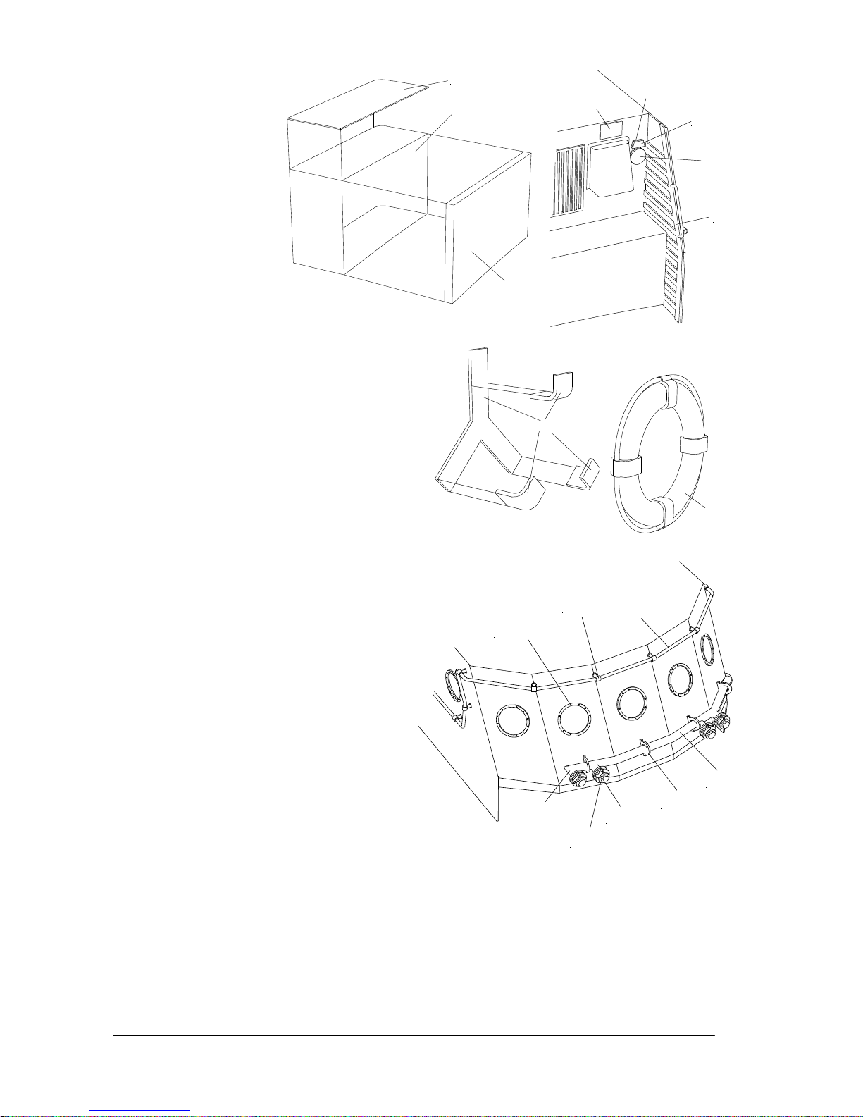
• Fertigen Sie das seitliche Wasserrohr (Pos.
240) an. TIPP: die Knickstellen mit einem
Fön erwärmen. Stecken Sie dann die
Wandhalter (Pos. 241) auf das Rohr. Kleben
Sie dann die Wandhalter an den Aufbau und
danach erst das Rohr in den Haltern fest. Fertigen Sie die Anschlussstutzen (Pos. 242) an. Stecken Sie
die Teile der C-Rohr
Schlauchanschlüsse (Pos.
243) auf die Anschlussstutzen
und kleben die Einheiten auf
das Wasserrohr.
• Bohren Sie für die
Relingstützen (Pos. 244) die
Löcher. Stecken Sie 5
Relingstützen auf die Reling
(Pos. 245) und stecken dann
die Stützen in die Bohrungen
im vorderen Teil vom Aufbau.
Arbeiten Sie sich immer
weiter vor, indem Sie immer
die Reling soweit biegen, bis
die Stütze in das jeweilige
Loch passt. Danach können
Sie die Reling verkleben.
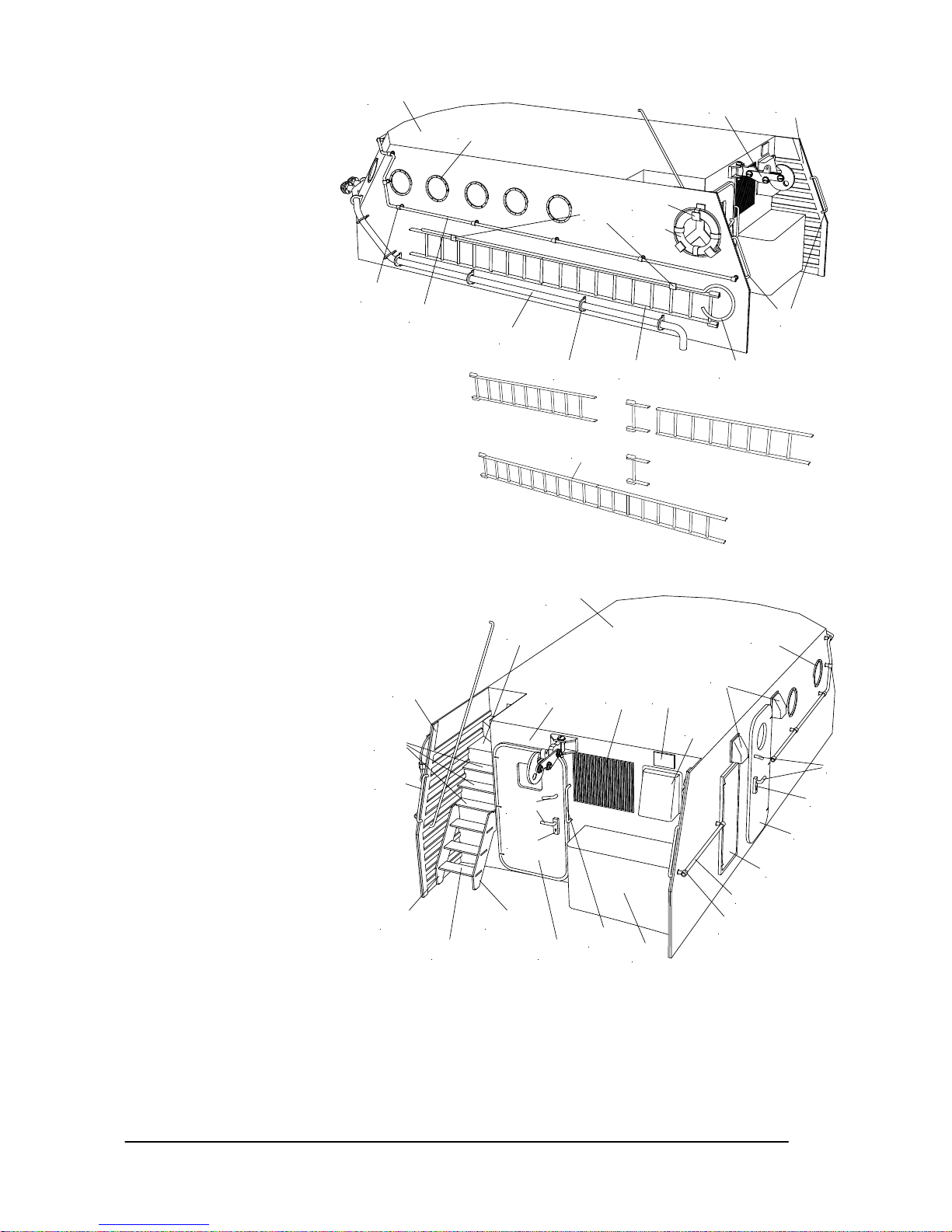
• Kleben Sie die Leiter (Pos.
246) zusammen. Trennen Sie
ein genau passendes Stück
von einer Leiter unten ab und
kleben diese Stücke dann
zusammen. Biegen Sie den
Fanghaken (Pos. 247) vor und kleben diesen auf die Leiter. Fertigen Sie die beiden Halter (Pos. 248) an
und kleben diese an die Leiter. Nach der Lackierung wird die ganze Einheit an den Aufbau geklebt.
• Fertigen Sie die Handgriffe für die Seitenwand (Pos. 249) an und kleben diese in die Absätze in der
Wandverstärkung. Bohren Sie für den Handgriff an der Rückwand (Pos. 250) die Löcher, fertigen dieses
an und kleben ihn in die Rückwand.
• Kleben Sie die untere Treppe (Pos. 251) zusammen. HINWEIS: es gibt eine kurze und eine lange
Wange, die lange Wange liegt an der Seitenwand an.
• Montieren Sie den Schlepphaken (Pos. 252) zusammen. Schleifen Sie den Halter soweit ab, bis die
pilzförmige Vertiefung weg ist. Kleben Sie den Haken an die Rückwand.
246
241
240
246
247
248
249
245
244
238
253
254
252
221.2
217
217
221.1
249
222
251.1 251.2
251.3
223
225
224
219
220
226
250
230
228
245
244
237
234
235
236
239
238
231
Page 20
GRAUPNER GmbH & Co. KG D-73230 KIRCHHEIM/TECK GERMANY
No liability for printing errors. Technnical modifications reserved. #0060384 04/2009
20
• Schneiden Sie den
Halter (Pos. 253) für
den Rettungsring aus
und kleben in
zusammen. Kleben
Sie diesen dann an
den Aufbau und
kleben danach den
Rettungsring (Pos.
254) in den Halter.
HINWEIS: der
Rettungsring ist nicht
auf allen Kreuzern
angebracht.
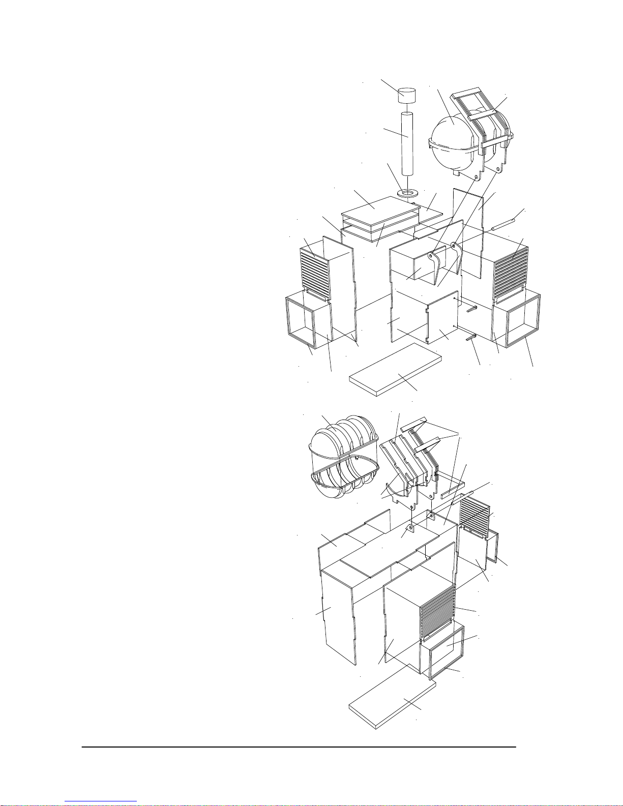
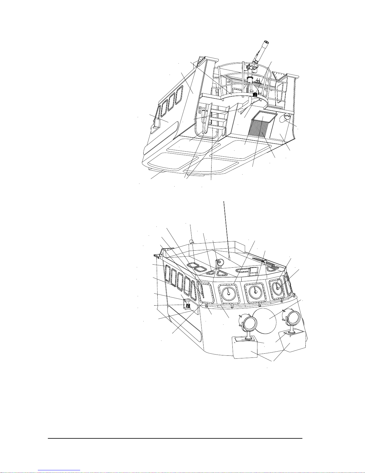
• Kleben Sie in den
Brückenaufbau (Pos.
255) den Innenrahmen (Pos. 256). Kleben Sie die Rückwand (Pos.
257) zusammen und dann die Monitorfläche an
die fertige Rückwand. Kleben Sie dann die
Einheit in die Brücke. HINWEIS: achten Sie auf
die richtige Position. Evtl. müssen Sie die
Rückwand in der Breite etwas anpassen, damit
sie ohne die Brücke zu verformen hineinpasst.
Kleben Sie in den schrägen Teil der Rückwand
innen die Verstärkung (Pos. 259) ein.
• Kleben Sie die Aufdopplungen (Pos. 260) an
die Brücke. Achten Sie auf die richtige Position.
• Kleben Sie unter die Monitorplatte die
Verstärkung (Pos. 261). Danach folgt der
Rahmen (Pos. 262) um die Monitorplatte.
• Kleben Sie das Lüftungsgitter (Pos. 263) an die
Rückwand. Fertigen Sie die
Lüfterabdeckung (Pos. 264) an, kleben Sie
diese aber erst zum Schluss auf.
• Schneiden Sie den Stutzen (Pos. 265) aus.
Kleben auf den Stutzen die Deckelplatte
(Pos.266) und darauf den Griff (Pos. 267).
Danach kleben Sie den Stutzen auf die
Grundplatte. HINWEIS: der Stutzen muss
nach Montage der Einheit gerade zur
Wasserlinie stehen.
• Kleben Sie die Tür (Pos. 269) an die
Rückwand. Kleben Sie die Schlossplatte
(Pos. 270), den Türgriff und die
Verriegelung (Pos. 271) an die Tür.
• Kleben Sie das kleine Lüftungsgitter (Pos.
273) an die Rückwand. Fertigen Sie die
Lüfterabdeckung (Pos. 274) an und kleben
diese über das Lüftungsgitter.
• Kleben Sie die Fensterrahmen (Pos. 275)
an die Rückwand.
• Bohren Sie für die Haltestange (Pos. 276) und die Reling (Pos. 277) die Löcher. Fertigen Sie die Stange
und die Reling an und kleben diese an die Rückwand.
• Kleben Sie die Mastseitenteile (Pos. 278) innen an die Seitenwände. HINWEIS: arbeiten Sie hier
möglichste genau, da sonst später der Mast nicht gerade auf dem Aufbau steht. Kleben Sie die beiden
Abdeckplatten (Pos. 279) innen an die Seitenteile. Die runde Platte an Backbord, die rechteckige an
Steuerbord.
• Schleifen Sie Stellen, wo die Scharnierplatten (Pos. 280) aufgeklebt werden, diese Stellen plan und
absolut parallel zueinander. Kleben Sie dann die Scharnierplatte auf. Achten Sie darauf, dass die
Bohrungen aufeinanderliegen. TIPP: mit passendem Ø1mm Draht lassen sich die Schrauben darstellen.
Kleben Sie danach das Scharnier (Pos. 281) an die Platten.
• Kleben Sie die Fensterrahmen (Pos. 282) an die Brücke. HINWEIS: die rechteckigen Seitenrahmen sind
231
233
232
254
253
242
243.1
241
240
243.2
238
245
244
229.1
229.2
229.3
221.2
230
Page 21
GRAUPNER GmbH & Co. KG D-73230 KIRCHHEIM/TECK GERMANY
No liability for printing errors. Technnical modifications reserved. #0060384 04/2009
21
nicht quadratisch, die
längere Seite steht vertikal.
Evtl. müssen Sie die
Öffnungen in der Brücke
noch etwas nacharbeiten,
bis die Rahmen genau
passen.
• Montieren Sie den
Löschmonitor (Pos. 283)
zusammen. Beginnen Sie
zuerst nur mit dem
Grundkörper. Kleben Sie
dann das Alurohr für das
Wasser ein, danach folgt
die Wasserdüse. Kleben
Sie dann die Verlängerung
(Pos. 284) an den
Grundkörper zuerst das
Ø4mm Stück, dann das
Ø5mm darüber. Darunter
kleben Sie dann den
Sockel. An die
Sockelflächen werden die
dreieckigen Seitenflächen
(Pos. 285) geklebt. Kleben
Sie dann die rechteckigen
Platten (Pos. 286) leicht
schräge an den
Grundkörper. Auf diese
werden die beiden
Handräder geklebt.
Fertigen Sie das
Werferrohr (Pos. 287) an,
auf dieses kommt das
Endstück (Pos. 288).
Danach kleben Sie das
Rohr über das Alurohr.
HINWEIS: das Werferrohr
dient nur zur optischen
Darstellung, daher sollte
die Wasserdüse nicht aus
dem Rohr herausstehen.
• Stellen Sie das
Versorgungsrohr (Pos.
289) her. Dieses Rohr
muss durch die Bohrung in
der Monitorfläche passen
und möglichst eng in den
Aufbau laufen. Im
Dachbereich vom Aufbau
müssen Sie einen Bereich
ausarbeiten, damit Sie bei
der verklebten Brücke/Aufbaueinheit an dieses Rohr kommen, um den Silikonschlauch anschließen zu können. Auf dem
herausstehenden Stutzen vom Versorgungsrohr auf der Monitorfläche kleben Sie später den
Löschmonitor.
• Fertigen Sie aus Relingstützen (Pos. 290) und den Relingbändern (Pos. 291) die Reling für die
Monitorfläche an.
• Fertigen Sie die Gräting (Pos. 292) aus der Kiefernleiste an. HINWEIS: diese Gräting unterscheidet sich
auf den Kreuzern, zeichnerisch dargestellt ist die von der Hans Hackmack. Kleben Sie erst nach der
Lackierung auf die Monitorfläche.
• Fertigen Sie den Hydraulikzylinder (Pos.293) an. Schrauben Sie hierzu die eine Augenschraube vom
313.1
313.2
313.3
282.5
282.4
282.3
310
31 1
299
300
305
302
301.1
301.2
301.3
282.1
282.2
309.1
309.2
309.3
308.1
308.2
256
255
265
268
263
264.1
264.2
261
384
289
321.1
321.2
323
260
262
Page 22
GRAUPNER GmbH & Co. KG D-73230 KIRCHHEIM/TECK GERMANY
No liability for printing errors. Technnical modifications reserved. #0060384 04/2009
22
Wantenspanner bis auf 2mm vom
Gewinde ein, die andere Seite
möglichst weit heraus und sicher
diese Seite mit Klebstoff. TIPP: um
eine möglichst realistische
Darstellung des Kolbens zu
erreichen, sollten Sie das Gewinde
soweit abschleifen, bis nur noch eine
Stange übrig bleibt. Kleben Sie die
Befestigungen (Pos. 294) für die
Zylinder zusammen. Als Achse
nehmen Sie Reststücke des Ø2mm
ABS Rundprofils. Kleben Sie die
Zylindereinheiten noch nicht an.
• Klipsen Sie den Suchscheinwerfer
(Pos. 295) aus dem Bügel,
Schneiden Sie dann die Verkleidung
(Pos. 296) aus und stecken den
Reflektor in die Verkleidung.
HINWEIS: die seitlichen
Markierungen für die Befestigung des
Haltebügels sind nicht
auf der Mittenachse der
Verkleidung, sondern
leicht nach unten
versetzt. Führen Sie
auch die Stromkabel
unten heraus. Kleben
Sie dann die
Verriegelungen (Pos.
297) und den Griff
(Pos. 298) an die
Verkleidung. Montieren
Sie dann den
Scheinwerfer wieder
zusammen.
• Schneiden Sie das
Fundament (Pos. 299)
aus. HINWEIS: es gibt
ein rechtes und linkes
Teil, dies ist durch eine
Markierung
gekennzeichnet.
Kleben Sie darauf die
Abdeckplatte (Pos.
300) auf. Achten Sie
auf die Position der
Bohrung. Bohren Sie
dann die Bohrung der
Platte durch. Kleben Sie dann die Fundamente an die Brücke. Die Scheinwerfer werden zum Schluss
montiert, achten Sie aber darauf, dass Sie eine Öffnung für die Kabeldurchführung schaffen.
• Kleben Sie die Positionslampenhalter (Pos. 301) zusammen und darauf eine Positionslampe (Pos. 302).
Wenn Sie die Lampe beleuchten wollen, sollten Sie eine Bohrung im Halter vorsehen, damit Sie eine
defekte Glühbirne wechseln können. Die fertigen Halter werden ebenfalls zum Schluss montiert.
• Kleben Sie auf das Namensschild (Pos. 303) je zwei Halter (Pos. 304). Dies wird ebenfalls beim Schild
für das Hansekreuz (Pos. 305) mit den Haltern (Pos. 306) ausgeführt. Alle Schilder werden zum Schluss
montiert.
• Fertigen Sie die Verglasung (Pos. 307) für Aufbau und Brücke an. Nach der Lackierung werden diese
innen eingeklebt. Verwenden Sie beim Verkleben von transparentem Material nur einen Kleber, der nicht
ausblüht, z.B. lösungsmittelfreien Sekundenkleber (auch Styroporsekundenkleber genannt).
• Kleben Sie auf die Schleuderscheibe (Pos. 308) je zwei Scheiben auf. Diese werden dann vorsichtig auf
die Verglasung geklebt. HINWEIS: auf dem Dekorbogen befinden sich Darstellungen der
283
287
288
283
286
283
284
285
283
260
280.2
280.1
281
312
267
266
278.3
278.2
278.1
279.1
282
290
291
313/314
316
317
324
325
327
328
326
258
275.2
275.3
275
Page 23

GRAUPNER GmbH & Co. KG D-73230 KIRCHHEIM/TECK GERMANY
No liability for printing errors. Technnical modifications reserved. #0060384 04/2009
23
Schleuderscheiben, diese können alternativ
verwendet werden.
• Kleben Sie die Scheibenwischer (Pos. 309)
zusammen und kleben diese an die seitlichen
Fenster.
• Bohren Sie für die Relingstützen (Pos. 310)
die Löcher, stecken in diese die Reling (Pos.
311) und kleben die Einheit dann auf die
Brücke.
• Schneiden Sie das Dach aus. HINWEIS: es
befinden sich im Bausatz Fensterahmen (Pos.
313) für die Dachfenster und alternativ
gleichgroße Abdeckungen (Pos. 314) für die
Fenster. Bei den Originalen wurden teilweise
aus Blendschutzgründen die Dachfenster
später zugeschweißt. Dies lässt sich mit den
Abdeckungen darstellen. Kleben Sie die
gewünschten Teile auf das Dach. Bei den
Fensterrahmen müssen Sie dann die
Öffnungen für die Fenster ausarbeiten und die
Verglasung (Pos. 315) anfertigen und
einkleben.
• Kleben Sie dann das Dach auf die Brücke,
evtl. müssen Sie die Rückwand vom Aufbau
anpassen, damit das Dach bündig und gerade
aufliegt. Kleben Sie dann den Seitenrahmen
(Pos. 316) an das Dach, die Übergänge der Teile zueinander müssen Sie anpassen.
• Kleben Sie die Instrumentenfläche (Pos. 317) auf das Cockpit. Auf dieser werden nach der Lackierung
das Dekor der Instrumente aufgebracht und darauf dann die beiden Maschinentelegrafen (Pos.318) und
der Ruderhebel (Pos. 319) aufgeklebt.
• Fertigen Sie das Gischtschutzfenster (Pos. 320) an. HINWEIS: auf dem Dekorbogen sind die Rahmen
dargestellt. Die doppelreihigen Rahmen stellen die vertikalen Rahmenverbindungen der Fenster
zueinander dar und dienen zugleich als Verbindung der Fenster untereinander. So brauchen Sie diese
hier nicht zu verkleben.
• Kleben Sie die Treppen (Pos. 321) zu Monitorplattform zusammen. Kleben Sie diese aber erst am
Schluss ein.
• Fertigen Sie den Handlauf (Pos. 323) an. Kleben Sie diesen in den Aufbau.
• Bohren Sie für die Dachantenne (Pos. 324) ein Loch in das Dach und kleben diese dann auf.
• Kleben Sie den Lautsprecher (Pos. 325) zusammen. Achten Sie darauf, dass der Trichter gerade zur
Wasserlinie steht. Kleben Sie den Lautsprecher dann auf.
• Kleben Sie den Scheinwerfer (Pos. 326) zusammen, das Reflektorgehäuse sollte direkt auf das
Backdeck strahlen.
• Die Stabantenne (Pos. 327) wird in den
Antennenfuß (Pos. 328) geklebt. Bohren Sie
dann ein Loch in das Dach und kleben die
Antenne dann ein.
• HINWEIS: beim Bau des folgenden
Bügelmasts müssen Sie vorher einen evtl.
Einbau einer Beleuchtung berücksichtigen,
ein späteres Verlegen der Kabel ist nicht
möglich.
• Schneiden Sie die Hälften der
Bügelmastteile (Pos. 329) aus, schleifen
diese plan und kleben diese zusammen.
• Schneiden Sie die Quertraverse (Pos. 330)
vom Bügelmast aus und schleifen diese
plan. Kleben Sie unten die Bodenplatte
(Pos. 331) ein. Passen Sie die beiden
Bügelmastteile an, diese müssen so
angepasst werden, damit der fertige
Bügelmast auf die beiden Stützen auf der
Brücke passt.
298
297
296
295
335.1
335.2
335.3
335.4
292
318
319
320
276
277
257.1
269
Page 24
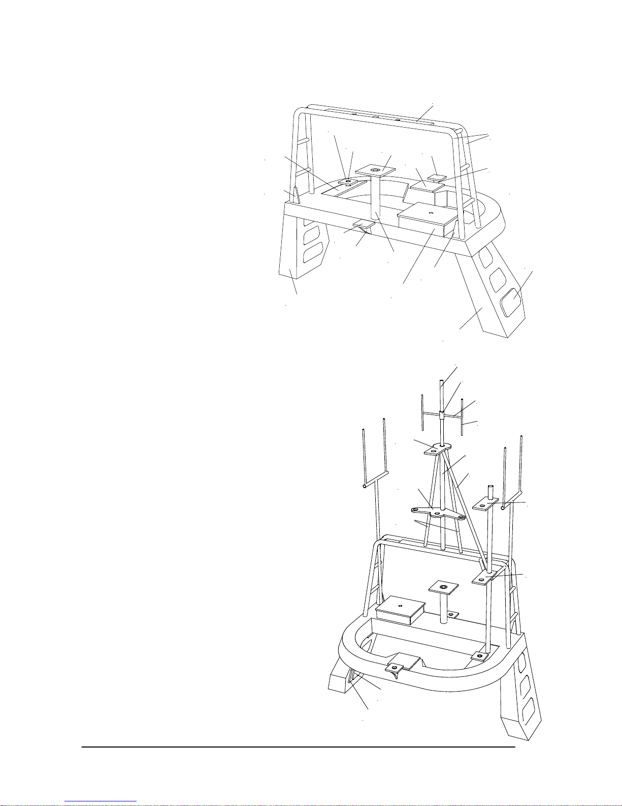
GRAUPNER GmbH & Co. KG D-73230 KIRCHHEIM/TECK GERMANY
No liability for printing errors. Technnical modifications reserved. #0060384 04/2009
24
• Kleben Sie die Standfläche für den Lampenmast (Pos. 332) in die Quertraverse. Die Querstange werden
aus Ø2mm Messingdraht gefertigt und eingeklebt.
• Kleben Sie die äußere
Abdeckplatte (Pos. 333) an den
rechten Bügelmast. Kleben Sie
dann die innere Abdeckplatte (Pos.
334) dann innen auf. Darüber
kleben Sie die kleine Abdeckplatte
mit dem Absatz nach unten.
• Kleben Sie den Kasten (Pos. 335)
für den Suchscheinwerfer
zusammen. Kleben Sie ihn dann
auf die Quertraverse. Der
Suchscheinwerfer wird, wie schon
bei den anderen beiden aus den
Pos. 295 bis 298 erstellt.
• Kleben Sie den vorderen
Lampenträger (Pos. 336) an den
Mast und darunter die Abstützung
(Pos. 337), derselbe Arbeitsgang
erfolgt bei den hinteren
Lampenträger (Pos. 338) und der
Abstützung (Pos. 339).
• Kleben Sie in die backbordseitigen
Lampenträger (Pos. 340) die
Stütze (Pos. 341). Bohren Sie
dann eine Ø3mm Bohrung in den
Bügelmast und kleben dann die Stütze hinein.
• Kleben Sie unter die Radarträgerplatte (Pos. 342)
die Stütze (Pos. 343). Kleben Sie die vordere
Radarträgerplatte (Pos. 345) auf die Quertraverse.
• Fertigen Sie die Mastbügel (Pos. 346). TIPP: die
Messingrohre lassen sich einfacher biegen, wenn
Sie etwas Bowdenzug-Innenrohr im Biegenbereich
hineinstecken. Bohren Sie die Löcher für die Bügel
in die Quertraverse und richten die Bügel aus.
Kleben Sie dann die Querfläche (Pos. 347)
zwischen die Mastbügel und die Bügel endgültig
fest. Dann folgen die beiden Abstützungen (Pos.
348).
• Fertigen Sie den Mittelmast (Pos. 349) an und
kleben diesen auf die Querfläche. Kleben Sie
darauf die Traverse 1 (Pos. 350), die beiden
Seitenstützen (Pos. 351), die Traverse 2 (Pos.
352) und darunter die Abstützung (Pos. 353).
Kleben Sie in den Mittelmast die Verlängerung
(Pos. 354) ein. Kleben Sie den Ring (Pos. 355)
auf. Bohren Sie vorsichtig für die quer stehenden
Antenne (Pos. 356) ein Loch. Daran löten Sie die
beiden vertikalen Antennen (Pos. 357). Kleben Sie
die Crewfinderantenne (Pos. 358) auf die
Verlängerung. In diese werden die Antennestäbe
(Pos. 359) geklebt.
• Fertigen Sie den Lampenmast (Pos. 360) an.
Kleben Sie darauf die Lampenträger und die
jeweiligen Abstützungen (Pos. 361 bis 365). Auf
diesen Mast wird die pilsförmige Antenne (Pos.
366) geklebt.
• Fertigen Sie die drei Abstützungen (Pos. 367 bis
369) an und kleben oder löten diese an den Mast.
• Fertigen Sie den Ausleger für den Mittelmast (Pos.
370) an und löten diesen an den Mittelmast.
342
343
338
339
337
336
346
347
345
330
333
329
329
348
332
340
341
348
335
334.1
334.2
364
361
351
369
349
350
352
357
356
355
354
Page 25
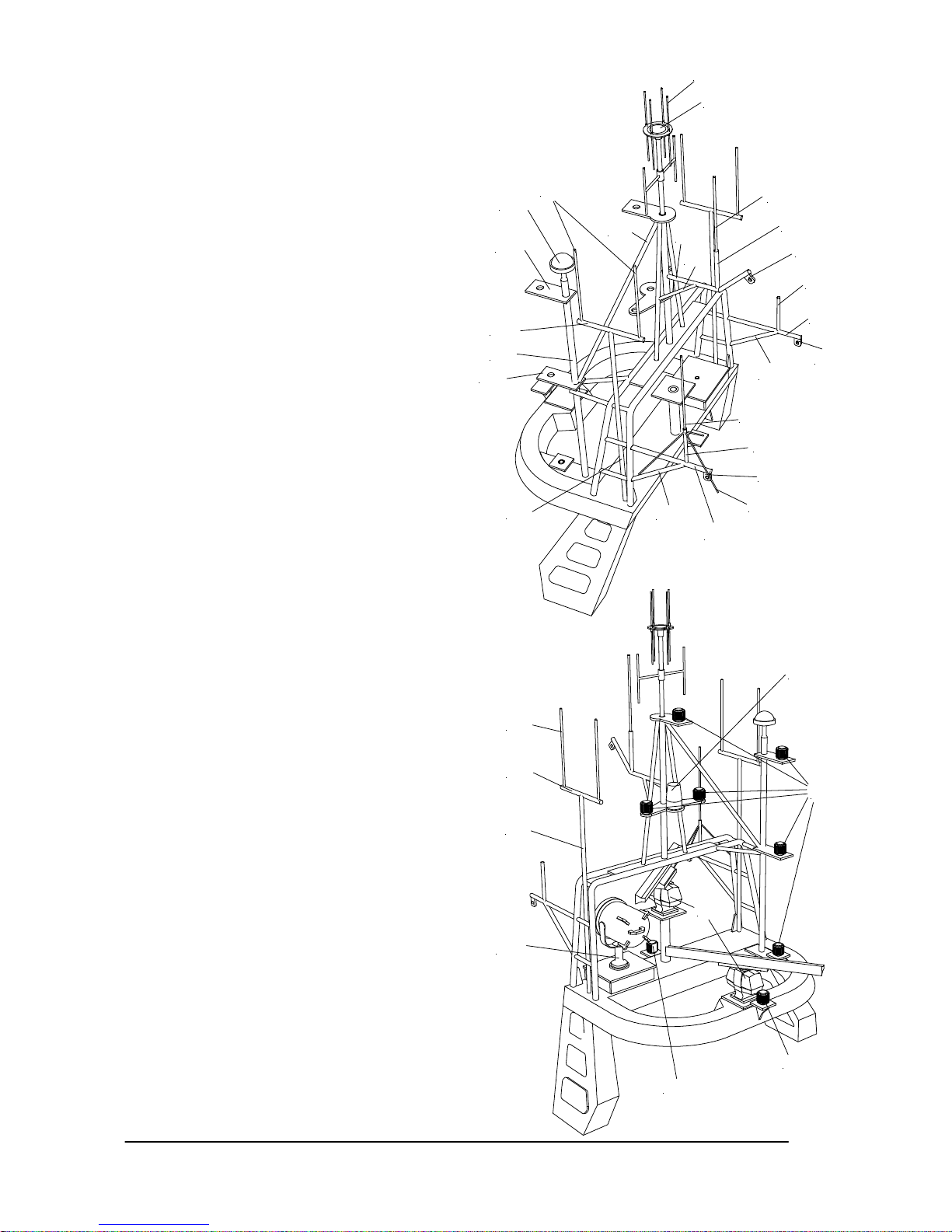
GRAUPNER GmbH & Co. KG D-73230 KIRCHHEIM/TECK GERMANY
No liability for printing errors. Technnical modifications reserved. #0060384 04/2009
25
Darauf werden der Antennenfuß (Pos. 371)
und darauf die Antenne (Pos. 372) gelötet.
Löten Sie dann die Abstrebungen (Pos. 373)
an. Kleben Sie die Öse (Pos. 374) an den
Ausleger.
• Fertigen Sie die Ausleger für den Bügelmast
aus den Pos. 375 bis 380 nach den selbem
Schema an. TIPP: an die Drähte den UKWAntennenabstrebung (Pos. 378) sollten Sie
einen Ring, passend zum Antennenfuß,
biegen. Dann lassen sich die Drähte leichter
verlöten.
• Fertigen Sie die beiden Antennenmasten aus
den Pos. 381 bis 383 an, bohren passende
Löcher in die Quertraverse und kleben diese
ein.
• Kleben Sie die Mastlampen (Pos. 384), die
Rundlampen (Pos. 385) und das Blaulicht
(Pos. 386) auf die jeweiligen Positionen.
• Schneiden Sie die Glocke (Pos. 387) aus,
stecken ein kurzes Reststück vom Ø0,5mm
Draht durch und kleben diese Einheit unter die
Quertraverse.
• Kleben Sie die Radarantennen (Pos. 388)
zusammen und dann auf die jeweiligen
Trägerplatten.
• Schleifen Sie vom Signalhorn (Pos. 389) die
Halbkugel plan. Schneiden Sie die Abdeckung
(Pos. 390) aus und kleben diese auf das
Signalhorn. Kleben Sie das Horn auf die
Querfläche.
• Fertigen Sie die Stabantenne (Pos. 391) an,
längen Sie den Antennenfuß (Pos. 392) und
die Antennenhalter (Pos. 393) an. Bohren Sie für
die Halter Löcher in die Bügelmastseitenteile und
kleben diese dort fest. Stecken Sie die
Antennenfüße dort ein und dann die
Stabantennen.
• Fertigen Sie die Gummifender (Pos. 394) an.
Stecken Sie die Mittenachsen (Pos. 395) in die
Fender und biegen je einen Ring an die Enden.
Befestigen Sie mit Schnur die Fender an den
Relingstützen. TIPP: durch den Draht im
Gummischlauch können Sie die Fender so
biegen, dass sie wie beim Original durch das
Eigengewicht durchhängen.
• Schneiden Sie die Rettungswesten (Pos. 396)
aus und kleben diese auf ABS Reste. Schneiden
Sie dann den Rand aus und schleifen den
Übergang rund. Kleben Sie dann die Westen auf
das Modell.
• Schneiden Sie die Kugelfender (Pos. 397) aus
und kleben diese zusammen. Befestigen Sie die
Fender dann mit Schnur an den beiden Pollern
auf den Seitenkästen.
• Kleben Sie jetzt noch alle verbliebenen Kleinteile
auf das Modell.
358
359
381
382
383
369
364
366
360
361
376
375
380
379
374
371
372
370
373
377
376
380
378
379
375
386
388
295
384
385
385
382
383
391
Page 26
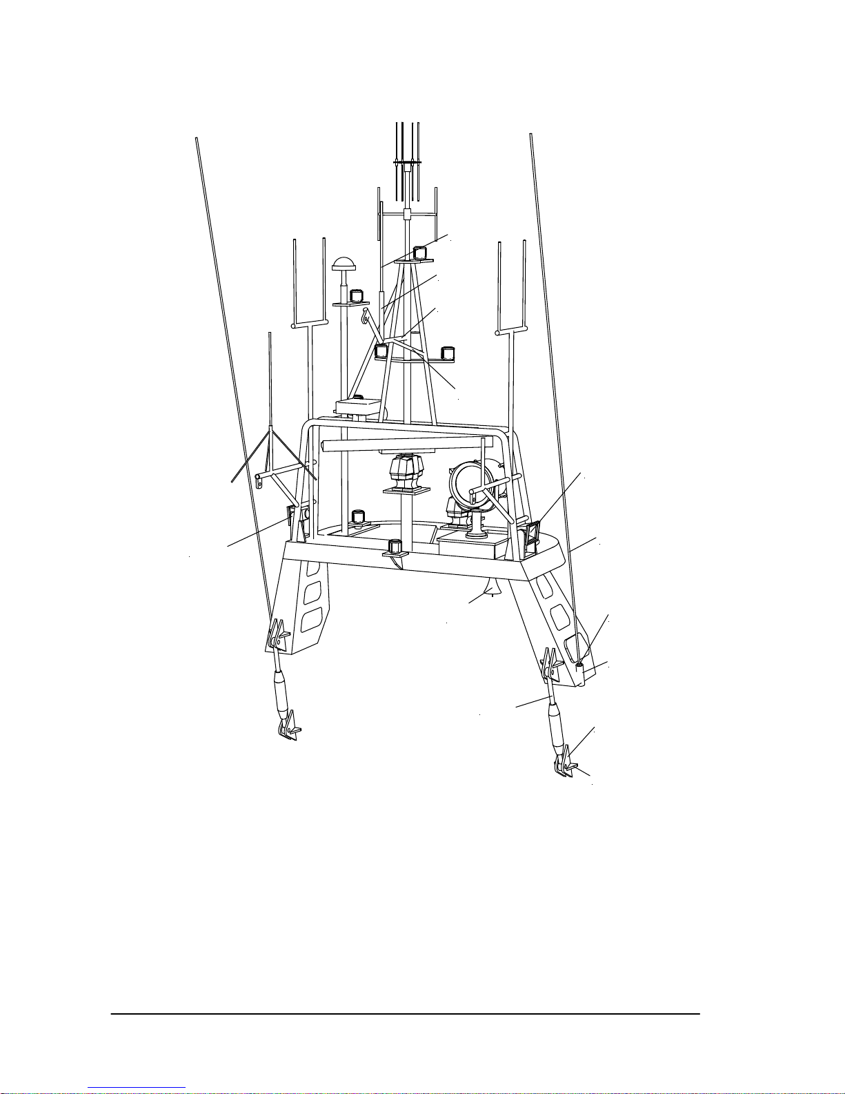
GRAUPNER GmbH & Co. KG D-73230 KIRCHHEIM/TECK GERMANY
No liability for printing errors. Technnical modifications reserved. #0060384 04/2009
26
387
393
392
391
293
294.1
294.2
326
326
373
370
371
372
Page 27
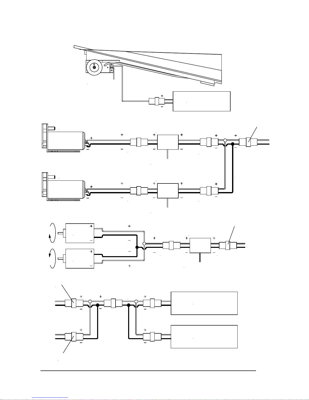
GRAUPNER GmbH & Co. KG D-73230 KIRCHHEIM/TECK GERMANY
No liability for printing errors. Technnical modifications reserved. #0060384 04/2009
27
Schaltplan
3061
Fahrtregler
zum Empfänger
Motor
Motor
G2 Stecker G2 Stecker
Fahrtregler
zum Empfänger
G2 Stecker
G2 Stecker
Wasserpumpe
Schottelpumpjet
3061
Fahrakku
Fahrakku
3068
A
B
Fahrtregler
zum Empfänger
G2 Stecker
G2 Stecker
Wasserpumpe
Löschmonitor
A
3068
B
Akku Segelwinde
zum Empfänger
Page 28

GRAUPNER GmbH & Co. KG D-73230 KIRCHHEIM/TECK GERMANY
No liability for printing errors. Technnical modifications reserved. #0060384 04/2009
28
Jungfernfahrt
Laden Sie alle Akkus und testen Sie die Funktionen des Modells. Kontrollieren Sie, ob alle aufgesteckten
Teile fest sitzen. Nun können Sie die Jungfernfahrt starten. Lassen Sie es bei der Jungfernfahrt langsam
angehen, machen Sie sich erst mit dem Fahrverhalten vertraut. Das Modell fährt relativ schnell und besitzt
einen langen Bremsweg und sollte daher auf einem geeigneten größeren Gewässer eingesetzt werden.
Fahren Sie auch anfangs nicht zu weit weg vom Ufer.
Viel Spaß beim Fahren mit Ihrem Modell Bernhard Gruben
Ersatzteile
Best.-Nr. Bezeichnung
2027.2 Rumpf, CNC-bearbeitet
2027.3 Back- und Hauptdeck, CNC-bearbeitet
Ferner wird benötigt (nicht im Lieferumfang enthalten)
Best.-Nr. Bezeichnung
4719 RC-Set mc-19S 40 MHz
2875 Fahrtregler NAVY V40R
5173 Segelwinde REGATTA eco (für Ansteuerung Tochterbootaufzug)
4101.LOSE Servo C577 (2 Stück erforderlich für Ansteuerung der Heckklappe und 1 Stück zur Auslösung des Hakens)
3302 SPEED 600 BB Turbo 12 (2 Stück erforderlich)
2591 Bleibatterie 12V 7Ah (2 Stück erforderlich)
1952 Zahnradpumpe 12V (2 Stück erforderlich)
2736 Micro Speed 10 (für Wasserpumpe Schottelpumpjetsimulation)
7125 PICO 25 (für Wasserpumpe Löschmonitor)
2490.6 GM Power-Pack 3600 NiMH 7,2V 3,6Ah (für Stromversorgung Segelwinde und Fernsteuerung)
3588 Entstörkondensatoren (insgesamt 4 Stück erforderlich)
3061 Parallelkabel G2
3068 Verteilerkabel G2
2989.5 Stecker und Buchse G2
Kabel (min. Querschnitt 2,5mm²) und andere Kleinteile nach eigenem Ermessen wählen
Empfehlenswert sind auch alle Graupner IFS Computer-Systeme ab Version 3, da diese einen sogenannten Simultanempfänger
ansteuern kann und damit die parallele Steuerung von Kreuzer und Tochterboot ermöglicht.
Page 29

GRAUPNER GmbH & Co. KG D-73230 KIRCHHEIM/TECK GERMANY
No liability for printing errors. Technnical modifications reserved. #0060384 04/2009
29
Hilfsfotos
Page 30

GRAUPNER GmbH & Co. KG D-73230 KIRCHHEIM/TECK GERMANY
No liability for printing errors. Technnical modifications reserved. #0060384 04/2009
30
Stückliste
Pos. Bene nnung Anzahl Material Abmessung und Stärke in mm
1 Schiffständer, Bug 2 Sperrholz 4 mm, ausgelasert
2 Schiffständer, Heck 2 Sperrholz 4 mm, ausgelasert
3 Schiffständer, Seite 4 Sperrholz 4 mm, ausgelasert
4 Rumpf 1 ABS Tiefziehteil, CNC-bearbeitet
5 Kielleiste 2 ABS 1mm, Laserteil
6 Schottelpumpjet 2 ABS 1mm, Laserteil
7 Stevenrohr 2 Metall Fertigteil
8 Motorträger 2 Kunststoff Fertigteil
9 Halter für Motorträger 1 Sperrholz 2mm, Laserteil
10 Motor 2 Metall Best.-Nr. 3302
11 Wellenkupplung 2 Aluminium Fertigteil
12 Wellenabstützung 4 ABS Fertigteil
13 Propeller, rechts 1 Kunststoff Fertigteil
14 Propeller, links 1 Kunststoff Fertigteil
15 Heckwand 1 ABS Tiefziehteil
16 Heckwandverstärkung 3 Sperrholz 4mm, Laserteil
17 Ruderkoker 2 Messing Ø4/3,1 x 40mm
18 Ruderwelle 2 Messing Ø3 x 90mm
19 Ruderblatt (2 Hälften) 2 ABS Tiefziehteil
20 Ruderkokerhalter 8 Sperrholz 2mm, Laserteil
21 Ruderhebel 2 Kunststoff Fertigteil
22 Gestängeanschluss 4 Metall Fertigteil
23 Rudergestänge, quer 1 Stahl Ø1,5 x 140mm
24 Ruderservohalter 5 Sperrholz 2mm, Laserteil
25 Ruderservo 1 Verschiedene Best.-Nr. 4101.LOSE oder aus RC-Set
26 Rudergestänge, längs 1 Stahl Ø1,5 x 180mm
27 Wasserpumpe 2 Verschiedene Best.-Nr. 1952
28 Anschlussstutzen, Schottel 2 Aluminium Rohr, Ø4/3,1 x 60mm
29 Ansaugstutzen, Monitor 1 Aluminium Rohr, Ø4/3,1 x 30mm
30 Silikonschlauch, Schottel 2 Silikon Rohr, Ø7/3 x 170mm
31 Silikonschlauch, Monitor 2 Silikon Rohr, Ø7/3 x 500mm + 150mm
32 Ankerklüse 1 ABS Tiefziehteil
33 Auflagefläche, Hakenservo 1 Sperrholz 4mm, aus Rinnenrahmen Aufbau
34 Auflagefläche, Fahrakkus 1 Sperrholz 4mm, Laserteil
35 Backdeck 1 ABS Tiefziehteil, CNC-bearbeitet
36 Backdeck, Verstärkung 3 Sperrholz 4mm, Laserteil
37 Oberlichter 4 Kunststoff 1mm, Rauchglas
38 Hauptdeck 1 ABS Tiefziehteil, CNC-bearbeitet
39 Hauptdeck, Verstärkung 5 Sperrholz 4mm, Laserteil
40 Heckwanne, Verstärkung 6 Kiefer Vierkantleiste, 5 x 8mm, anpassen
41 Scheuerleiste, unten 4 ABS Tiefziehteil
42 Sprayrail 2 ABS Tiefziehteil
43 Scheuerleiste, Verlängerung 2 ABS Tiefziehteil
44 Heckwanne 1 ABS Tiefziehteil
45 Verstärkungsrahmen 5 Sperrholz 4mm, Laserteil
46 Seilführung 2 Messing Rohr, Ø3/2 x 210 und Ø3/2 x 25 mm
47 Rollenhalter, innen 8 ABS 1mm, Laserteil
48 Rollenachsen 4 Messing Draht, Ø1,5 x 13mm
49 Rolle 4 Kunststoff Fertigteil
50 Tochterbootaufzug 1 Messing Fertigteil
51 Segelwinde 1 Verschiedene Best.-Nr. 5173
52 Zugseil 1 Polyester Ø0,8 x 1500mm
53 Rollenhalter, klein 4 ABS 1mm, Laserteil
54 Rollendrehlager 2 Nylon Rohr, Ø1,9/0,9 x 25mm
55 Rollenachse 2 Stahl Draht, Ø0,8 x 25mm
56 Rolle 2 ABS Rohr, Ø4/2 x 22mm
Page 31

GRAUPNER GmbH & Co. KG D-73230 KIRCHHEIM/TECK GERMANY
No liability for printing errors. Technnical modifications reserved. #0060384 04/2009
31
57 Rolle, Außenring 4 ABS Rohr, Ø5/4 x 6mm
58 Befestigungsschraube 8 Edelstahl Linsenkopf Ø2,2 x 9,5mm
59 Führungsrollenhalter, Seite 14 ABS 1mm, Laserteil
60 Rollendrehlager 2 Nylon Rohr, Ø1,9 x 33mm
61 Rollenachse 2 Stahl Draht, Ø0,8 x 33mm
62 Rolle 2 ABS Rohr, Ø4/2 x 29mm
63 Heckklappe 1 ABS Tiefziehteil
64 Seitenwandverstärkungen 2 ABS 1mm, Laserteil
65 Innenspantgerüst 18 ABS 1mm, Laserteil
66 Gestängeanschluss 2 Metall Fertigteil
67 Scharnierrohr 4 ABS Rohr, Ø3,2/2,1 x 6mm
68 Abdeckung 2 ABS 1mm, Laserteil
69 Heckverkleidung 1 ABS 1mm, Laserteil
70 Mittelscharnier 6 ABS 1mm, Laserteil
71 Mittelscharnierrohr 1 ABS Rohr, Ø3,2/2,1 x 24mm
72 Außenscharnierrohr 2 ABS Rohr, Ø3,2/2,1 x 20mm
73 Scharnierstift, mittig 1 Nylon Rohr, Ø1,9/0, 9 x 50mm
74 Scharnierstift, außen 2 Nylon Rohr, Ø1,9/0,9 x 40mm
75 Führungsrohr 2 ABS Rohr, Ø3,2/2,1 x 60mm
76 Bowdenzug 2 Nylon Rohr, Ø1,9/0,9 x 200mm
77 Servohebelverlängerung 2 Sperrholz 2mm, Laserteil
78 Befestigungsschrauben 4 Edelstahl Linsenkopf Ø2,2 x 9,5mm
79 Gestängeanschluss 2 Metall Fertigteil
80 Heckklappenservo 2 Verschiedene Best.-Nr. 4101.LOSE
81 Führungsrollenhalter 6 ABS 1mm, Laserteil, ein Paar höher
82 Rollendrehlager 3 Nylon Rohr, Ø1,9 x 30mm
83 Rollenachse 3 Stahl Draht, Ø0,8 x 30mm
84 Rolle 3 ABS Rohr, Ø4/2 x 27mm
85 Rolle, Außenring 6 ABS Rohr, Ø5/4 x 7,5mm
86 Führungsrollenhalter, unten 4 ABS 1mm, Laserteil
87 Rollendrehlager, unten 2 Nylon Rohr, Ø1,9 x 28mm
88 Rollenachse, unten 2 Stahl Draht, Ø0,8 x 28mm
89 Innenrolle, unten 2 ABS Rohr, Ø4/2 x 25mm
90 Außenrolle, unten 2 ABS Rohr, Ø5/4 x 25mm
91 Führungsrollenhalter, mitte 4 ABS 1mm, Laserteil
92 Rollendrehlager, mitte 2 Nylon Rohr, Ø1,9 x 50mm
93 Rollenachse, mitte 2 Stahl Draht, Ø0,8 x 50mm
94 Innenrolle, mitte 2 ABS Rohr, Ø4/2 x 47mm
95 Außenrolle, mitte 2 ABS Rohr, Ø5/4 x 18mm
96 Führungsrollenhalter, oben 4 ABS 1mm, Laserteil
97 Rollendrehlager, oben 2 Nylon Rohr, Ø1,9 x 58mm
98 Rollenachse, oben 2 Stahl Draht, Ø0,8 x 58mm
99 Innenrolle, oben 2 ABS Rohr, Ø4/2 x 55mm
100 Außenrolle, oben 2 ABS Rohr, Ø5/4 x 55mm
101 Heckklappenbügel 1 ABS Rund, Ø5 x 130mm
102 Rollenhalter, seitlich 10 ABS 1mm, Laserteil
103 Rollenhalter, Abstützung 6 ABS 1mm, Laserteil
104 Führungsrollenhalter, seitlich 4 ABS 1mm, Laserteil
105 Rollendrehlager, seitlich 2 Nylon Rohr, Ø1,9 x 52mm
106 Rollenachse, seitlich 2 Stahl Draht, Ø0,8 x 52mm
107 Innenrolle, seitlich 2 ABS Rohr, Ø4/2 x 47mm
108 Außenrolle, seitlich 2 ABS Rohr, Ø5/4 x 47mm
109 Schanzkleid, Innenwand 2 ABS 1mm, Laserteil
110 Schanzkleid, Verstärkung 2 ABS 1mm, Laserteil
111 Schanzkleid, Stütze 4 ABS 1mm, Laserteil
112 Schanzkleid, Innenstrebe 2 ABS 1mm, Laserteil
113 Schanzkleid, Stützenauflage 4 ABS 1mm, Laserteil
114 Treppenstufe, unten 2 ABS 1mm, Laserteil
115 Treppenstufe, oben 2 ABS 1mm, Laserteil
Page 32

GRAUPNER GmbH & Co. KG D-73230 KIRCHHEIM/TECK GERMANY
No liability for printing errors. Technnical modifications reserved. #0060384 04/2009
32
116 Riffelblech 4 ABS Tiefziehteil
117 Schanzkleid 1 ABS Tiefziehteil
118 Schanzkleidfender, Backbord 1 ABS Tiefziehteil
119 Schanzkleidfender, Steuerb. 1 ABS Tiefziehteil
120 Bugklüse 2 ABS Tiefziehteil
121 Seitenkästen 8 ABS 1mm, Laserteil
122 Seitenklüsen 2 ABS Fertigteil
123 Schanzkleid, Bügel 2 ABS 1mm, Laserteil
124 Schanzkleid, Stütze 1 2 ABS 1mm, Laserteil
125 Schanzkleid, Stütze 2 2 ABS 1mm, Laserteil
126 Schanzkleid, Stütze 3 2 ABS 1mm, Laserteil
127 Schanzkleid, Stütze 4 2 ABS 1mm, Laserteil
128 Schanzkleid, Stütze 5 2 ABS 1mm, Laserteil
129 Schanzkleid, Stütze 6 2 ABS 1mm, Laserteil
130 Schanzkleid, Stütze 7 2 ABS 1mm, Laserteil
131 Schanzkleid, Auflage 1 2 ABS 1mm, Laserteil
132 Schanzkleid, Auflage 2 2 ABS 1mm, Laserteil
133 Schanzkleid, Auflage 3 2 ABS 1mm, Laserteil
134 Schanzkleid, Auflage 4 2 ABS 1mm, Laserteil
135 Schanzkleid, Auflage 5 2 ABS 1mm, Laserteil
136 Schanzkleid, Auflage 6 2 ABS 1mm, Laserteil
137 Schanzkleid, Auflage 7 1 ABS 1mm, Laserteil
138 Schanzkleid, Auflagefläche 1 ABS 1mm, Laserteil
139 Schwanenhalslüfter 3 ABS Fertigteil
140 Bugflaggenstock 1 Messing Rohr, Ø3/2 x 58mm
141 Flaggenstockring 1 ABS 1mm, Laserteil
142 Flaggenstockkappe 1 ABS 1mm, Laserteil
143 Sprungtuchmast, oben 2 Aluminium Rohr, Ø4/3 x 54mm
144 Sprungtuchmast, unten 2 Aluminium Rohr, Ø5/4 x 50mm
145 Mastplatte, unten 2 ABS 1mm, Laserteil
146 Mastplatte, oben 2 ABS 1mm, Laserteil
147 Mastabstützung, mitte 2 ABS 1mm, Laserteil
148 Mastabstützung, unten 2 ABS 1mm, Laserteil
149 Seilhalter 2 ABS 1mm, Laserteil
150 Grundplatte, Schalterkasten 1 ABS 1mm, Laserteil
151 Schalterkasten 1 ABS Tiefziehteil
152 Schalter 1 ABS Fertigteil
153 Doppelkreuzpoller 3 ABS Fertigteil
154 Ankerkettenklüse 1 ABS Tiefziehteil
155 Mannlochdeckel, groß 1 ABS 1mm, Laserteil
156 Mannlochdeckel, klein 1 ABS 1mm, Laserteil
157 Achse 2 ABS Rund, Ø2mm x 3mm
158 Handrad 2 ABS Fertigteil
159 Bodenplatte, Winsch 1 ABS 1mm, Laserteil
160 Deckelplatte, Winsch 1 ABS 1mm, Laserteil
161 Getriebeabdeckung, Winsch 3 ABS 1mm, Laserteil
162 Handrad 1 ABS 1mm, Laserteil
163 Achse, Handrad 1 Stahl Rund, Ø1,5 x 13mm
164 Winsch 1 ABS Tiefziehteil
165 Kettenstopper 5 ABS Fertigteil
166 Handrad 1 ABS 1mm, Laserteil
167 Achse, Handrad 1 Stahl Rund, Ø1,5 x 15mm
168 Kettendurchführung 2 ABS Tiefziehteil
169 Kettenabdeckung 1 ABS 1mm, Laserteil
170 Ankerkette 1 Messing Fertigteil, Länge ca. 150mm
171 Mannlochdeckel, groß 2 ABS 1mm, Laserteil
172 Handrad 2 ABS Fertigteil
173 Achse 2 ABS Rund, Ø2mm x 3mm
174 Doppelkreuzpoller 6 ABS Fertigteil
Page 33

GRAUPNER GmbH & Co. KG D-73230 KIRCHHEIM/TECK GERMANY
No liability for printing errors. Technnical modifications reserved. #0060384 04/2009
33
175 Kreuzpoller 2 ABS Fertigteil, n.Z.
176 Endkappe 2 ABS 1mm, Laserteil
177 Schwanenhalslüfter 2 ABS Fertigteil
178 Kasten, quer 33 ABS 1mm, Laserteil
179 Bodenplatte 2 Sperrholz 4mm, Laserteil
180 Riffelblech 1 ABS Tiefziehteil
181 Verriegelungen 5 ABS 1mm, Laserteil
182 Fanghaken 1 Messing Laserteil, n.Z.
183 Linsenkopfschraube 1 Messing M2 x 10mm
184 Unterlegscheibe 2 Messing Ø4,5 x 2,2mm
185 Stoppmutter 1 Messing M2
186 Zugseil 1 Polyester Ø0,8 x 250mm
187 Hakenservo 1 Verschiedene Best.-Nr. 4101.LOSE
188 Ansaugkasten, Steuerbord 18 ABS 1mm, Laserteil
189 Ansaugkasten, Backbord 13 ABS 1mm, Laserteil
190 Bodenplatte 2 Sperrholz 4mm, Laserteil
191 Verriegelung 2 ABS 1mm, Laserteil
192 Rettungsinsel 2 ABS Tiefziehteil
193 Rettungsinselhalter 18 ABS 1mm, Laserteil
194 Drehachse 2 ABS Rund, Ø2mm x 24mm
195 Abgasrohr, Abdeckung 1 ABS Tiefziehteil
196 Abgasrohr 1 Aluminium Rohr, Ø8/7 x 45mm
197 Auspuffverkleidung 2 ABS Tiefziehteil
198 Abdeckblech, vorne 2 ABS 1mm, Laserteil
199 Abdeckblech, hinten 2 ABS 1mm, Laserteil
200 Bodenplatte 2 Sperrholz 4mm, Laserteil
201 Trittkasten, Steuerbord 7 ABS 1mm, Laserteil
202 Trittkasten, Backbord 9 ABS 1mm, Laserteil
203 Bodenplatte, Steuerbord 1 Sperrholz 4mm, Laserteil
204 Bodenplatte, Backbord 1 Sperrholz 4mm, Laserteil
205 Riffelblech 5 ABS Tiefziehteil
206 Haltestange 1 Messing Rund, Ø2 x 40mm
207 Steckdose 1 ABS Tiefziehteil
208 Schutzbügel 13 ABS Rund, Ø4 x Längen anpassen
209 Bugreling 6 Messing Rund, Ø1,5mm, Längen anpassen
210 Relingstützen 30 Messing Fertigteil
211 Kreuzpoller 8 ABS Fertigteil
212 Relingbänder 20 Messing Rund, Ø1,5mm, Längen anpassen
213 Schutzkappen 8 ABS Winkel, 3 x 3 x 25mm
214 Kranfundament 1 ABS Tiefziehteil
215 Anker 1 ABS Tiefziehteil
216 Ankerstock 1 ABS 1mm, Laserteil
217 Aufbau 1 ABS Tiefziehteil, CNC-bearbeitet
218 Innenrahmen, Aufbau 1 Sperrholz 4mm, Laserteil
219 Rückwand 1 ABS 1mm, Laserteil
220 Treppe 1 ABS Tiefziehteil
221 Wandverstärkungen 2 ABS 1mm, Laserteil
222 Treppenstufen 3 ABS 1mm, Laserteil
223 Tür, Rückwand 1 ABS 1mm, Laserteil
224 Schlossplatte 1 ABS 1mm, Laserteil
225 Türgriff + Verriegelung 2 Stahl Rund, Ø1,5 x 10mm
226 Lüftungsgitter 1 ABS 1mm, Laserteil
227 Lüfterabdeckung 2 ABS 1mm, Laserteil
228 Verkleidung, groß 1 ABS Tiefziehteil
229 Glocke 2 ABS 1mm, Laserteil
230 Werftschild 1 ABS 1mm, Laserteil
231 Kasten 1 ABS Tiefziehteil
232 Innenrahmen 1 Sperrholz 4mm, Laserteil
233 Riffelblech 1 ABS Tiefziehteil
Page 34

GRAUPNER GmbH & Co. KG D-73230 KIRCHHEIM/TECK GERMANY
No liability for printing errors. Technnical modifications reserved. #0060384 04/2009
34
234 Tür, Seitenwand, groß 1 ABS 1mm, Laserteil
235 Schlossplatte 1 ABS 1mm, Laserteil
236 Türgriff + Verriegelung 2 Stahl Rund, Ø1,5 x 10mm
237 Tür, Seitenwand, klein 1 ABS 1mm, Laserteil
238 Fensterrahmen 12 ABS 1mm, Laserteil
239 Verkleidung, klein 2 ABS Tiefziehteil
240 Wasserrohr 1 ABS Rund, Ø5 x 600mm
241 Wandhalter 10 ABS 1mm, Laserteil
242 Anschlussstutzen 4 ABS Rund, Ø5 x 12mm
243 C-Rohr Schlauchanschlüsse 4 ABS 1mm, Laserteil
244 Relingstützen 17 ABS Fertigteil
245 Reling 2 ABS Rund, Ø2mm, Länge anpassen
246 Leiter 1 ABS Fertigteil, n. Z.
247 Fanghaken 1 Stahl Rund, Ø1,5 x 280mm
248 Halter, Leiter + Fanghaken 2 ABS Winkel, 3 x 3 x 25mm
249 Handgriff, Seitenwand 2 Stahl Rund, Ø1,5 x 40mm
250 Handgriff, Rückwand 1 Stahl Rund, Ø1,5 x 40mm
251 Untere Treppe 1 ABS 1mm, Laserteil
252 Schlepphaken 1 ABS Fertigteil
253 Halter für Rettungsring 4 ABS Tiefziehteil
254 Rettungsring 1 ABS Fertigteil
255 Brückenaufbau 1 ABS Tiefziehteil, CNC-bearbeitet
256 Innenrahmen, Brücke 1 Sperrholz 4mm, Laserteil
257 Rückwand 4 ABS 1mm, Laserteil
258 Monitorfläche 1 ABS 1mm, Laserteil
259 Verstärkung, Rückwand 1 Sperrholz 4mm, Laserteil
260 Aufdoppelung, Mast 2 ABS 1mm, Laserteil
261 Verstärkung, Monitorplatte 1 ABS 1mm, Laserteil
262 Rahmen, Monitorplatte 4 ABS 1mm, Laserteil
263 Lüftungsgitter 1 ABS 1mm, Laserteil
264 Lüfterabdeckung 2 ABS 1mm, Laserteil
265 Stutzen 1 ABS Tiefziehteil
266 Deckelplatte, Stutzen 1 ABS 1mm, Laserteil
267 Griff 1 ABS 1mm, Laserteil
268 Grundplatte, Stutzen 1 ABS 1mm, Laserteil
269 Tür, Brücke 1 ABS 1mm, Laserteil
270 Schlossplatte 1 ABS 1mm, Laserteil
271 Türgriff + Verriegelung 2 Stahl Rund, Ø1,5 x 10mm
273 Lüftungsgitter, klein 1 ABS 1mm, Laserteil
274 Lüfterabdeckung, klein 2 ABS 1mm, Laserteil
275 Fensterrahmen, Rückwand 2 ABS 1mm, Laserteil
276 Haltestange 1 Stahl Rund, Ø1,5 x 90mm
277 Reling, Rückwand 2 Stahl Rund, Ø1,5, Länge anpassen
278 Mast, Seitenteile 6 ABS 1mm, Laserteil
279 Abdeckplatten 2 ABS 1mm, Laserteil
280 Scharnierplatten 4 ABS 1mm, Laserteil
281 Scharnier 2 ABS Rohr, Ø3,2/2,1 x 23mm
282 Fensterrahmen, Brücke 14 ABS 1mm, Laserteil
283 Löschmonitor 1 ABS Fertigteil
284 Löschmonitor, Verlängerung 2 Aluminium Rohr, Ø6/5 x 12mm und Ø5/4 x 10mm
285 Zusatzteile, Sockel 8 ABS 1mm, Laserteil
286 Zusatzteile, Handräder 2 ABS 1mm, Laserteil
287 Werferrohr 1 Aluminium Rohr, Ø6/5 x 35mm
288 Werferrohr, Endstück 1 Aluminium Rohr, Ø7/6 x 8mm
289 Versorgungsrohr 1 Aluminium Rohr, Ø4/3, Länge anpassen
290 Relingstützen 4 Messing Fertigteil
291 Relingbänder 3 Messing Rund, Ø1,5mm, Länge anpassen
292 Gräting 1 Kiefer Vierkant, 3 x 2mm, Länge anpassen
293 Hydraulikzylinder 2 Aluminium Fertigteil
Page 35

GRAUPNER GmbH & Co. KG D-73230 KIRCHHEIM/TECK GERMANY
No liability for printing errors. Technnical modifications reserved. #0060384 04/2009
35
294 Befestigung, Zylinder 4 ABS 1mm, Laserteil
295 Suchschweinwerfer 3 Messing Fertigteil
296 Verkleidung, Scheinwerfer 3 ABS Tiefziehteil
297 Verriegelung 12 ABS 1mm, Laserteil
298 Griff 3 ABS 1mm, Laserteil
299 Fundament 2 ABS Tiefziehteil
300 Abdeckplatte, Fundament 2 ABS 1mm, Laserteil
301 Positionslampenhalter 8 ABS 1mm, Laserteil
302 Positionslampe 2 ABS Fertigteil
303 Namensschild 2 ABS 1mm, Laserteil
304 Halter, Namensschild 4 ABS 1mm, Laserteil
305 Schild, Hansekreuz 1 ABS 1mm, Laserteil
306 Halter, Hansekreuzschild 2 ABS 1mm, Laserteil
307 Verglasung 17 Kunststoff Transparent, n. Z.
308 Schleuderscheibe 3 ABS 1mm, Laserteil
309 Scheibenwischer 2 ABS 1mm, Laserteil
310 Relingstützen 5 ABS Fertigteil
311 Reling 1 ABS Rund, Ø2mm, Länge anpassen
312 Dach 1 ABS Tiefziehteil
313 Fensterrahmen 9 ABS 1mm, Laserteil
314 Fensterabdeckungen 9 ABS 1mm, Laserteil
315 Verglasung 7 Kunststoff Transparent, n. Z.
316 Seitenrahmen 7 ABS 1mm, Laserteil
317 Armaturenfläche 1 ABS 1mm, Laserteil
318 Maschinentelegraf 2 ABS Fertigteil
319 Ruderhebel 1 ABS Fertigteil
320 Gischtschutzfenster 5 Kunststoff Transparent, n. Z.
321 Treppe, Monitorplattform 5 ABS 1mm, Laserteil
323 Handlauf für Treppe 2 Stahl Rund, Ø1,5, Längen anpassen
324 Dachantenne 1 ABS Fertigteil
325 Lautsprecher 1 ABS Fertigteil
326 Scheinwerfer 3 ABS Fertigteil
327 Stabantenne 1 Stahl Draht, Ø0,8 x 100mm
328 Antennenfuß 1 Nylon Rohr, Ø1,9 x 15mm
329 Bügelmast, Seitenteile 2 ABS Tiefziehteil
330 Bügelmast, Quertraverse 1 ABS Tiefziehteil
331 Bügelmast, Bodenplatte 1 ABS 1mm, Laserteil
332 Standfläche, Lampenmast 1 ABS 1mm, Laserteil
333 Abdeckplatte, Außen 1 ABS 1mm, Laserteil
334 Abdeckplatte, Innen 2 ABS 1mm, Laserteil
335 Kasten, Suchscheinwerfer 6 ABS 1mm, Laserteil
336 Lampenträger, vorne 1 ABS 1mm, Laserteil
337 Lampenabstützung, vorne 1 ABS 1mm, Laserteil
338 Lampenträger, hinten 1 ABS 1mm, Laserteil
339 Lampenabstützung, hinten 1 ABS 1mm, Laserteil
340 Lampenträger, Backbord 1 ABS 1mm, Laserteil
341 Lampenstütze, Backbord 1 Messing Rohr, Ø3/2 x 10mm
342 Radar, Trägerplatte 1 ABS 1mm, Laserteil
343 Radarabstützung 1 Messing Rohr, Ø4/2 x 30mm
344 Wird nicht verwendet
345 Radar, Trägerplatte, vorne 1 ABS 1mm, Laserteil
346 Mastbügel 2 Messing Rohr, Ø3/2, Länge anpassen
347 Mastbügel, Querfläche 1 ABS 1mm, Laserteil
348 Mastbügel, Abstützung 2 ABS 1mm, Laserteil
349 Mittelmast 1 Messing Rohr, Ø3/2 x 76mm
350 Mittelmast, Traverse 1 1 ABS 1mm, Laserteil
351 Mittelmast, Seitenstützen 2 Messing Draht, Ø2 x 78mm
352 Mittelmast, Traverse 2 1 ABS 1mm, Laserteil
353 Abstützung, Traverse 2 1 ABS 1mm, Laserteil
Page 36

GRAUPNER GmbH & Co. KG D-73230 KIRCHHEIM/TECK GERMANY
No liability for printing errors. Technnical modifications reserved. #0060384 04/2009
36
354 Mittelmast, Verlängerung 1 Messing Draht, Ø2 x 46mm
355 Mittelmast, Ring 1 Messing Rohr, Ø3/2 x 5mm
356 Antenne, quer 1 Messing Draht, Ø1,5 x 30mm
357 Antenne, vertikal 2 Messing Draht, Ø1,5 x 24mm
358 Crewfinderantenne 1 ABS Fertigteil
359 Antennenstäbe 4 Stahl Draht, Ø0,8 x 35mm
360 Lampenmast 1 Messing Rohr, Ø3/2 x 125mm
361 Lampenträger, mitte 1 ABS 1mm, Laserteil
362 Wird nicht verwendet
364 Lampenträger, oben 1 ABS 1mm, Laserteil
365 Wird nicht verwendet
366 Antenne 1 ABS Fertigteil
367 Lampenmast, Abstützung 1 1 Messing Draht, Ø2 x 32mm
368 Lampenmast, Abstützung 2 1 Messing Draht, Ø2 x 25mm
369 Lampenmast, Abstützung 3 1 Messing Draht, Ø2 x 78mm
370 Mittelmast, Ausleger 1 Messing Draht, Ø2 x 50mm
371 Mittelmast, Antennenfuß 1 Messing Draht, Ø2 x 22mm
372 Mittelmast, Antenne 1 Messing Draht, Ø1,5 x 40mm
373 Mittelmast, Abstrebungen 2 Messing Draht, Ø1,5 x 18mm
374 Öse 1 ABS 1mm, Laserteil
375 Bügelmast, Ausleger 2 Messing Draht, Ø2 x 55mm
376 Bügelmast, Antennenfuß 2 Messing Draht, Ø2 x 22mm
377 Bügelmast, UKW Antenne 1 Messing Draht, Ø1,5 x 55mm
378 UKW Antenneabstrebungen 3 Messing Draht, Ø0,5 x 30mm
379 Bügelmast, Abstrebungen 2 Messing Draht, Ø1,5 x 35mm
380 Öse 2 ABS 1mm, Laserteil
381 Antennenmast, seitlich 2 Messing Draht, Ø2 x 105mm
382 Antennenmast, Quertraverse 2 Messing Draht, Ø2 x 33mm
383 Antenne 4 Messing Draht, Ø0,5 x 40mm
384 Mastlampe 2 ABS Fertigteil
385 Rundlampe 7 ABS Fertigteil
386 Blaulicht 1 ABS Fertigteil
387 Glocke 1 ABS Tiefziehteil
388 Radarantenne 2 ABS Fertigteil
389 Signalhorn 1 ABS Fertigteil
390 Signalhorn, Abdeckung 1 ABS Tiefziehteil
391 Stabantenne 2 Stahl Draht, Ø0,8 x 250mm
392 Antennenfuß 2 Nylon Rohr, Ø1,9 x 12mm
393 Antennenhalter 2 ABS Rohr, Ø3,2 x 10mm
394 Gummifender 8 Neoprene Schlauch Ø5/3, Länge anpassen
395 Mittenachse 8 Messing Draht, Ø1,5, Länge anpassen
396 Rettungsweste 4 ABS Tiefziehteil
397 Kugelfender 2 ABS Tiefziehteil
398 Kabelaufwicklung, klein 1 ABS Tiefziehteil
In der Stückliste sind auch Teile aufgeführt, die nicht im Baukasten enthalt en sind und separa t erworben werden müssen
n. Z. = nach Zeichnung, Maße aus dem Bauplan entnehmen
Pos. Nr. mit Strichnummer = diese Strichnummern sind gedacht, damit die Einzelteile des Gesamtteils leichter zugeordnet
werden können
Page 37

GRAUPNER GmbH & Co. KG D-73230 KIRCHHEIM/TECK GERMANY
No liability for printing errors. Technnical modifications reserved. #0060384 04/2009
37
Zuordnung der Pos.-Nr. der Laserteile
Part number assignments for the laser-cut parts
9
20.1
20.2
20.3
20.1
20.3
20.2
24.1
24.2
24.3
24.4
24.5
77
1
1
2
2
3
45.1
45.2
45.3
45.4
45.5
200
204
203
232
Page 38

GRAUPNER GmbH & Co. KG D-73230 KIRCHHEIM/TECK GERMANY
No liability for printing errors. Technnical modifications reserved. #0060384 04/2009
38
5
6
114
115
216
176
171.1
171.2
109
110
111
111
112
112
113
59.1
59.2
59.3
59.4
59.5
59.6
16.1
16.2
33
34
36.1
36.2
36.3
39.1
39.2
39.3
179
190
218
256
259
Page 39

GRAUPNER GmbH & Co. KG D-73230 KIRCHHEIM/TECK GERMANY
No liability for printing errors. Technnical modifications reserved. #0060384 04/2009
39
121.1
121.2
121.3
121.4
123
138
141
142
146
145
147148
149
150
156
155.1
155.2
159
160
161
162
166
169
124
131
125
132
126
133
127
134
128
135
129
136
130
137
47
53/81.1
64
65.1
65.2
65.3
65.4
65.5
65.6
65.7
65.8
65.9
65.10
65.11
68
69
70
103
103
103
103
102.1
102.2
102.3
102.4
104.1
104.2
104.1
104.2
81.2
86/91/96
Page 40

GRAUPNER GmbH & Co. KG D-73230 KIRCHHEIM/TECK GERMANY
No liability for printing errors. Technnical modifications reserved. #0060384 04/2009
40
199
199
198
198
201.1
201.2
201.3
201.4
201.5
201.6
201.7
202.1
202.3
202.2
202.4
202.7
202.8
202.9
202.6
202.5
219
221.2
222
223
224
226
227.1
227.2
221.1
229.1
229.2
229.3
230
234
235
237
238
238
238
241
243.1
243.2
251.1
251.2
251.3
238
258
257.1
257.2
257.3
257.4
261
262.1
262.2
262.3
262.4
263
264.1
264.2
266
267
268
269
270
273
274.1
274.2
275
285
286
308.1
308.2
309.1 309.2
309.3
317
321.2
321.1
305
306
303
304
297
298
300
301.1
301.2
301.3
282.1
282.2
282.2
282.3
282.3
282.4
282.4
282.5
Page 41

GRAUPNER GmbH & Co. KG D-73230 KIRCHHEIM/TECK GERMANY
No liability for printing errors. Technnical modifications reserved. #0060384 04/2009
41
260
313.1
313.2
313.3
314.4
314.5
314.6
331
332
297
298
294.1
294.2
316.1
316.2
333
334.1
334.2
335.1
335.2
335.3
335.4
336
337
338
339
347
348
374/380
340
342
345
278.2
278.1
278.3
278.2
278.1
279.1
279.2
280.1
280.2
350
352
361/364
Page 42

GRAUPNER GmbH & Co. KG D-73230 KIRCHHEIM/TECK GERMANY
No liability for printing errors. Technnical modifications reserved. #0060384 04/2009
42
178.1
178.2
178.3
178.4
178.5
178.6
178.7
178.8
178.9
178.10
178.11
178.12
178.13
178.14
178.15
178.16
178.17
178.18
178.19
178.20
178.21
178.22
178.23
178.24
178.25
178.26
181
178.27
178.28
193.1
193.2
193.3
193.4
193.5
189.1
189.2
189.3
189.4
189.5
191
188.1
188.2
188.3
188.4
188.5
188.6
188.7
188.8
188.9
188.10
188.11
188.12
188.13
1 18.14
188.16
188.15
189.11
189.12
189.13
189.14
189.15
189.16
Page 43

GRAUPNER GmbH & Co. KG D-73230 KIRCHHEIM/TECK GERMANY
No liability for printing errors. Technnical modifications reserved. #0060384 04/2009
43
Assembly instructions for the BERNHARD GRUBEN model boat, Order No.: 2027
History of the full-size vessel
The four ships of the 23.1 m class were built for the DGzRS (German Association for the Rescue of the
Shipwrecked) at the Schweers dockyard at Bardenfleth in the years 1996 and 1997. In October 1996 the
Hermann Rudolf Meyer and the Hans Hackmack were launched jointly, followed almost exactly one year
later by the Bernhard Gruben and the Theo Fischer. These vessels were named in honour of the foreman
and engineer of the Alfried Krupp, who lost their lives during an accident on the open seas in January 1995.
These cruisers are the first of the DGzRS’s ships to be designed for gas protection operation, and are also
the first ships of their type with an enclosed bridge. Since 05.08.1997 the Bernhard Gruben has been
stationed at the Norderney rescue station.
Description of the model
• Kit for the experienced marine modeller
• Vacuum-moulded ABS hull, deck and superstructure components, CNC-trimmed
• Many laser-cut ABS superstructure and deck parts
• Kit includes a full fittings set consisting of injection-moulded, vacuum-moulded and laser-cut ABS parts,
plus brass railing stanchions, working searchlights, etc.
• Comprehensive decal set including markings for all four individual ships
• Set contents: laser-cut ABS parts for superstructure, companionways, winches, window frames,
ventilation grilles, stern boxes and other parts, laser-cut wooden parts for internal bulkheads, reinforcements and boatstand, complete fittings set, factory-assembled mechanism for lowering and
recovering the ship’s boat, mechanical parts for opening and closing the stern flap
• The ship’s boat, Johann Fidi, is not included in the kit, Order No. 2027. It is available separately under
Order No. 2027.100.
• This is a comprehensive, finely detailed kit for the experienced marine modeller who enjoys some real
construction work. Nevertheless, construction time is shortened considerably by the many laser-cut
components and moulded parts (factory-trimmed using CNC-machines) which help greatly in producing
those assemblies which are difficult to make, and in abbreviating the repetitive tasks.
• Scale model of the 23 m cruiser based on original documents supplied by the Deutsche Gesellschaft zur
Rettung Schiffbrüchiger (German Association for the Rescue of the Shipwrecked - www.dgzrs.de).
Specification
Length approx. 1160 mm
Beam approx. 300 mm
Overall height approx. 640 mm
All-up weight incl. RC approx. 10 kg
Scale approx. 1 : 20
Manufacturer’s declaration from Graupner GmbH & Co. KG
Content of the manufacturer’s declaration
If material defects or manufacturing faults should arise in a product distributed by us in the Federal Republic
of Germany and purchased by a consumer (§ 13 BGB), we, Graupner GmbH & Co. KG, D-73230
Kirchheim/Teck, Germany, acknowledge the obligation to correct those defects within the limitations
described below.
The consumer is not entitled to exploit this manufacturer’s declaration if the failure in the usability of the
product is due to natural wear, use under competition conditions, incompetent or improper use (including
incorrect installation) or external influences.
This manufacturer’s declaration does not affect the consumer’s legal or contra ctual rights regarding defects
arising from the purchase contract between the consumer and the vendor (dealer).
Extent of the guarantee
If a claim is made under guarantee, we undertake at our discretion to repair or replace the defective goods.
We will not consider supplementary claims, especially for reimbursement of costs relating to the defect (e.g.
installation / removal costs) and compensation for consequent damages unless they are allowed by statute.
This does not affect claims based on legal regulations, especially according to product liability law.
Guarantee requirements
Page 44

GRAUPNER GmbH & Co. KG D-73230 KIRCHHEIM/TECK GERMANY
No liability for printing errors. Technnical modifications reserved. #0060384 04/2009
44
The purchaser is required to make the guarantee claim in writing, and must enclose original proof of
purchase (e.g. invoice, receipt, delivery note) and this guarantee card. He must send the defective goods to
us at his own cost, using the following address:
Graupner GmbH & Co. KG, Service Department,
Henriettenstr. 94 - 96, D-73230 Kirchheim / Teck, Germany
The purchaser should state the material defect or manufacturing fault, or the symptoms of the fault, in as
accurate a manner as possible, so that we can check if our guarantee obligation is applicable.
The goods are transported from the consumer to us and from us to the consumer at the risk of the
consumer.
Duration of validity
This declaration only applies to claims made to us during the claim period as stated in this declaration. The
claim period is 24 months from the date of purchase of the product by the consumer from a dealer in the
Federal Republic of Germany (date of purchase). If a defect arises after the end of the claim period, or if the
evidence or documents required according to this declaration in order to make the claim valid are not
presented until after this period, then the consumer forfeits any rights or claims from this declaration.
Limitation by lapse of time
If we do not acknowledge the validity of a claim based on this declaration within the claim period, all claims
based on this declaration are barred by the statute of limitations after six months from the time of
implementation; however, this cannot occur before the end of the claim period.
Applicable law
This declaration, and the claims, rights and obligations arising from it, are based exclusively on the pertinent
German Law, without the norms of international private law, and excluding UN re tail law.
Important safety notes
Important safety notes
You have acquired a kit which can be assembled into a fully working RC model when fitted out with suitable
accessories. However, we as manufacturers have no control over the way you build and operate your RC
model boat, nor how you install, operate and maintain the associated components, and for this reason we
are obliged to deny all liability for loss, damage or costs which are incurred due to the incompetent or
incorrect use and operation of our products, or which are connected with such operation in any way. Unless
otherwise prescribed by binding law, the obligation of the GRAUPNER company to pay compensation,
regardless of the legal argument employed, is excluded. This includes personal injury, death, damage to
buildings, damage due to loss of business or turnover, interruption of business or other direct or indirect
consequent damage whose root cause was the operation of the model.
The total liability in all cases is limited to the amount of money which you actually paid for this model.
This model boat is built and operated at the sole and express responsibility of the operator. The only
way to avoid injury to persons and damage to property is to handle and operate the model with the
greatest care and consideration at all times.
Before you run the model for the first time please check that your private third-party insurance covers the
operation of model boats of this kind. If in doubt, take out a special insurance policy designed to cover
modelling risks.
These safety notes should be kept in a safe place. If you ever dispose of the model, be sure to pass them on
to the new owner.
Page 45

GRAUPNER GmbH & Co. KG D-73230 KIRCHHEIM/TECK GERMANY
No liability for printing errors. Technnical modifications reserved. #0060384 04/2009
45
The following points are important and must be observed at all times:
• This model is not suitable for young persons under fourteen years of age.
• The projecting parts of the model may be sharp, and the aerials and masts could cause eye injuries.
• Bear in mind that tools can be dangerous; always be careful when handling them.
• Never operate the model when there are persons or animals in the water, as its relatively high speed
constitutes a considerable injury hazard.
• Never run your model in protected sites, animal or plant sanctuaries or sites of special scientific interest
(SSSIs). Check with your local authority that the stretch of water you wish to use is suitable for model
boats.
• Never run the boat in salt water.
• Never run the boat in adverse conditions, e.g. rain, storm, strong wind, choppy water or strong currents.
• Read the instructions provided with your radio control system and accessories, and observe the
recommendations.
• Before you run the model check that the radio control system is working reliably, and that all con-
nections are secure.
• Dry batteries must never be recharged. Only batteries marked as “rechargeable” are safe to recharge.
• Check the range of the radio control system before each session: ask a friend to walk about 100 m
away from the model carrying the transmitter. Your assistant will be able to tell you whether all the
working functions operate correctly at this range.
• Ensure that the frequency on which you intend to transmit is not already in use by other modellers.
Never run your boat if you are not certain that your channel is free.
• Bear in mind that other radio equipment and transmitting stations can cause serious interference to the
model. Ensure that no equipment of this type is being used in the vicinity while you are operating the
model.
• Do not carry out any work on the drive train unless you have already disconnected the battery.
• When the drive batteries are connected, keep well clear of the area around the rotating parts - the
propellers in particular - and make sure any spectators do the same.
• Do not be tempted to exceed the recommended operating voltage. Higher voltages may cause the
motor or speed controller to overheat, and the electrical cables may even melt. If this should happen,
the model could easily be ruined.
• Check that all the drive train components work smoothly and freely. This applies especially when the
boat is running, as leaves and other debris may get caught in the power system components. The motor
and speed controller could then be ruined by overloading.
• Dry cells and rechargeable batteries must never be short-circuited. Do not allow them to come into
direct contact with water.
• Remove the rechargeable battery and the dry cells in the transmitter and receiver pack if the model is to
be transported, or will not be used for a long period.
• Do not subject the model boat to high levels of humidity, heat, cold or dirt.
• Secure the model and your RC equipment carefully when transporting them. They may be seriously
damaged if they are free to slide about.
• Never operate the boat in moving water (e.g. a river), as any fault which develops could result in the
model drifting off downstream.
•
If you have to salvage the boat, take care not to risk your own life or that of others.
• Take particular care to ensure that the boat is completely watertight, as it will sink if too much water
enters the hull. Check the model for damage before every run, and ensure that water cannot penetrate
through the shaft bearings or the rudder bush.
• Allow the boat to dry out thoroughly after each session.
• Be sure to check repeatedly during the first run that the shaft systems are watertight. If water enters the
hull through the shaft tubes, remove the shafts and lubricate the tubes with plenty of grease, Order No.
570.
• NOTE: the electric motors installed in the model must not be discarded in the household rubbish. When
it is worn out, it should be removed from the boat and taken to your local collection point for electrical
waste.
• NOTE: if you are using drive batteries wired in parallel, please remember that they should only be
connected while the boat is running. If the batteries are inter-connected under no-load conditions, they
may interact with each other and suffer damage. For this reason you should connect the batteries just
before running the boat, and disconnect them again immediately after the run. Never store the batteries
with the parallel cables connected.
Page 46

GRAUPNER GmbH & Co. KG D-73230 KIRCHHEIM/TECK GERMANY
No liability for printing errors. Technnical modifications reserved. #0060384 04/2009
46
Notes on building the model
• Before starting construction it is essential to study the plan and read right through the building instructions, referring constantly to the Parts List. In general terms the instructions and the parts list reflect the
sequence of assembly.
• This model is intended for the highly experienced marine modeller, and for this reason the instructions
do not describe all stages of construction in detail. The recommended sequence of assembly is also
intended as no more than a general guide. However, all the important and crucial stages are des-cribed
accurately and in full detail.
• Please be aware of the hazards involved in the use of tools.
• The model’s surfaces should be rubbed down using 600-grit wet-and-dry abrasive paper; this grade of
abrasive is also ideal for surfaces which are subsequently to be painted.
• If you intend to fit supplementary working systems, it is essential to plan their installation before you start
construction.
• Each electric motor and each water pump must be fitted with a 470 nF suppressor capacitor (Order No.
3588); solder the capacitor across the motor terminals to form a bridge.
• Deploy all electrical cables neatly, wherever possible without crossing them over. Never allow a positive
wire to make electrical contact with a negative wire. Secure all wiring in such a way that it is impossible
for any cable to foul the rotating parts of the power system; cable-ties are a good solution.
• Be sure to use a grade of cable which is capable of carrying the currents which flow when the boat is
operating. If you fit the recommended components, a conductor cross-section of 2.5 mm² (e.g. Order No.
3689) is adequate.
• Deploy the receiver aerial as far away as possible from high-current cables (at least 3 cm).
• The propeller shaft system should be lubricated using a type of grease or oil which does not con-
taminate or soil water (e.g. grease: Order No. 570; oil: Order No. 206).
• Remove all traces of grease from components before gluing them. A good method is to sand the surface lightly, then rub with a non-greasy liquid detergent solution or white spirit. The same applies to
surfaces to be painted, as paint will not adhere properly to a greasy surface.
• Recommended adhesives for joining different materials:
Material – Material Suitable adhesives
Plastic motor mount - wood Cyano-acrylate (“cyano”)
ABS - wood Cyano-acrylate, UHU acrylit
ABS - ABS Cyano-acrylate, UHU acrylit, UHU plast spezial
ABS - metal Cyano-acrylate, UHU a c rylit
Wood - wood Cyano-acrylate, UHU hart, white glue
Wood- metal Cyano-acrylate
Always observe the processing instructions supplied by the adhesive manufacturer. The building instructions contain notes regarding the use
of particular adhesives, and it is important to keep to these recommendations. Special safety measures are necessary when using acetone,
white spirit and other solvents as cleaning agents; please read and observe the instructions stated on the packaging.
Notes on installing and setting up the daughter boat lift
Our main purpose in developing this lift system was to reproduce as accurately as possible both the
appearance of the original lift and its method of operation. We also wanted to make it a straightforward task
to remove the entire sub-assembly from the rescue cruiser for purposes of maintenance. A drive spindle
would have been one solution, but this takes up a great deal of space; instead our system employs a winch,
with the result that all the required components can be attached to the daughter boat cradle. To remove the
system all you have to do is undo the screwed joints involving the cradle, release the winch cable and the
watertight joint between the cradle and the stern wall, and the lift can then be removed from the vessel
complete with the cradle, providing excellent access to the rudder control system and the stern flap
mechanism.
Method of working
• The daughter boat is housed in the rescue cruiser’s stern cradle, where it is secured by the capture hook
alone. In this basic position the arms of the lift are disengaged from the daughter boat. When the stern
flap is opened, all you have to do is disengage the capture hook, and the daughter boat slides out of the
stern cradle. Since this system is powered by gravity alone, it is clearly important to ensure that the
rollers in the stern cradle and the stern flap are free-moving.
• Once the daughter boat has left the stern cradle, the lift slide is moved into the lower pick-up position.
The arms are now automatically lowered, so that the daughter boat can pass over the slide as it runs into
the cradle, without becoming caught on any obstacle.
• When the daughter boat is located in the stern cradle, the lift is moved to the upper position: the cap-ture
arms of the slide now rise automatically, and engage in the daughter boat. If the daughter boat is not
Page 47

GRAUPNER GmbH & Co. KG D-73230 KIRCHHEIM/TECK GERMANY
No liability for printing errors. Technnical modifications reserved. #0060384 04/2009
47
positioned correctly relative to the lift, it is very likely that it will not be captured successfully. For this
reason it is important to practise the procedure so that you are able to position the daughter boat as
required. TIP: we recommend that the daughter boat should be drawn up with the motor running, as this
pushes it further into the stern cradle and centres it more effectively. NOTE: the instructions for Order
No. 2027.100 state that a 25 mm Ø propeller is required, but subsequent experience has shown that this
no longer applies.
• The capture hook engages immediately before the boat stops at the upper position, and at the same
time the capture arms of the slide descend automatically. At this point the stern flap can be closed.
NOTE: the optimum settings are not all that easy to determine; you must be prepared to carry out careful
adjustments on your particular model to allow for constructional tolerances.
• The cruiser’s draught should be set up in such a way that the daughter boat is easily able to run into the
cradle. NOTE: the weight of the daughter boat has a marked effect on the rescue vessel’s draught at the
stern; this means that the draught must first be adjusted without the daughter boat on board. The
vessel’s stern will dip quite deeply into the water when the daughter boat is on board; this is exactly what
happens on the full-size vessels.
• You can also influence the position of the daughter boat relative to the cruiser by adjusting the opening
angle of the stern flap. Once again, practical testing will be required in order to optimise this angle.
Controlling the capture arms
The two capture arms are linked by a bar which engages along the side-mounted guide rails. This bar
actually moves the capture arms, and must on no account be removed. Each capture arm features an
internal U-shaped spring, which holds the arms permanently raised when at rest. They are lowered to the
bottom position when the capture arm bar runs up against the stops on the side-mounted guide rails. When
in the upper position, the system is designed in such a way that the bar’s upper cross-strut runs up against
the cover plate located above the end of the rail (in the transverse box), thereby pressing the capture arms
down. The wire springs are made of stainless steel wire, so it is not necessary to treat them to prevent rust.
Adjusting the capture arms
The final task is to adjust the capture arms by bending them to the point where they reliably engage in the
daughter boat. You may find it necessary to reduce the width of the capture arms slightly where they engage
in the daughter boat; this can be accomplished by careful use of a file. NOTE: repeated bending may cause
the sheet brass component to fracture, especially when bent through a tight radius, so please be very careful
when bending.
[ Adjust this edge if necessary ]
The function of the capture hook
The capture hook engages in the daughter boat immediately before the capture arms are lowered; the
hook’s own weight is sufficient to achieve this. Please ensure that the hook ‘overbalances’ at the end facing
the daughter boat; this simply means that this end has to be longer (approx. 2/3 of the overall hook length).
The hook must move with absolute freedom on its mountings; this includes the cable guide from the hook to
the hook servo. It is also very important that no cables etc. are left very close to the pull-cord, where they
could foul it, as this would prevent the operator having full control over the hook’s movement.
Attaching the capture bar to the daughter boat
At the daughter boat the bar on which the capture hook engages is fitted in such a way that it lies parallel to
the deck when the boat is in its cradle. The actual position should be selected to ensure that the hook is also
horizontal when it is engaged. The lift’s retaining pin (termed the ‘lift retaining bar’ in the instructions for No.
2027.100) should use a length of snake outer sleeve (3.2 / 2.1 mm Ø) inside the hull, with a suitable length
of snake inner sleeve (1.85 / 0.9 mm Ø) inside it acting as the actual retaining pin. This works very well as a
reliable method of capture, and its flexibility prevents it breaking off if the daughter boat should become
snagged at any point. Experience has shown that the alternative system described in the daughter boat
building instructions does not guarantee the same reliability of operation.
Construction of the rollers
The basic construction of the rollers is: snake inner sleeve as axle, ABS tube as the actual roller, and laser-
Die s e Kante evtl. anpass en
Page 48

GRAUPNER GmbH & Co. KG D-73230 KIRCHHEIM/TECK GERMANY
No liability for printing errors. Technnical modifications reserved. #0060384 04/2009
48
cut ABS parts as brackets. Particular rollers - especially the vertical ones, and those which are severely
stressed - should be fitted with a length of 0.8 mm Ø steel wire inside the sleeve axle, forming an inner axle.
The ends of the steel wire should project by about 4 mm, and can then be bent over at right-angles to
prevent the axle slipping out. TIP: an alternative method is to cut the wire core in the centre, bend the ends
over, then insert one piece from each end and glue them in place.
In the case of the less highly stressed axles it is sufficient to leave the snake inner sleeve slightly overlength, fit the mounting brackets, then cut the sleeve neatly to the correct length. It is important that the tube
should not be crimped or squashed at the ends, so please avoid cutting them to length with side-cutters or
scissors. If the ends are not a good fit in the brackets, there is a chance that the rollers will be pushed out of
the brackets when under load.
Painting
• We recommend that you ask your local model shop or paint dealer for advice on the best paints to use.
• Always observe the application notes supplied with the paints.
• Use ONLY paints of the same make and type, otherwise the materials may react when in contact, and
attack or dissolve each other or produce unsightly bubbles. Be particularly careful when combining
spray-can paints and brushing types; always carry out a test beforehand on a scrap piece of material, to
check whether the paints are compatible with each other.
• The surfaces must be rubbed down beforehand to ensure that the paint adheres well. Use fine-grade
wet-and-dry paper (600-grit to 800-grit) for this, then remove all traces of grease from the surface using a
non-greasy liquid detergent or white spirit. Make every effort to avoid touching the cleaned surface
before the paint is applied, as perspiration will deposit a new layer of grease on the surface.
• All areas which are not to be painted must be masked off completely. Seal all holes, slots and openings
with tape, as the fine mist of paint will find its way into any opening, no matter how small.
• Where you wish to mask off neat, straight edges, use as narrow an adhesive tape as possible, e.g. trimstripe tape. Apply the tape neatly and accurately, without placing it under tension, then cover the
remaining areas with paper masking tape and scrap paper or film.
• Before starting construction please consider carefully how and in which sequence you intend to paint the
model, or simply keep to the sequence recommended in the building instructions. Note that some parts
will be difficult or even impossible to paint once glued in place.
• TIP: a good method of painting small parts is to attach them temporarily to a scrap hardwood stick or
similar holder using double-sided tape, fixing them by the joint surface. The part can then be painted in
one “go”, then removed from the tape and attached to the model once the paint is dry.
Colour scheme
The list below states only the RAL colours, as this will make it easier for you to find the correct hues. Armed
with this information you can ask any paint supplier or specialist model shop to prepare the paints for you.
Let your advisor in the paint shop know exactly how you intend to use the material, as this will help him
select the correct grade. We recommend synthetic enamels; never use cellulose paints!
Exposed hull, superstructure, bulwark, deck-boxes, mast, small items,
guard bars, railings, searchlights, fire monitor plinth RAL 9016
Submerged hull RAL 3009
Decks, stern cradle, bollards, small items, companionway steps RAL 6001
Command stand, inside surface of bulwarks RAL 6019
Fluorescent paint for superstructure and mast RAL 3024
Fender rail, searchlights, loudhailers, anchor RAL 9006
Bulwark fenders, lifebelts RAL 2003
Ball-fenders RAL 2002
Fire monitor RAL 3000
Upper part of exhaust fairing, parts of guard bar,
bow flagstock, upper area of jumping sheet masts RAL 9005
Assignment of roof registrations to ship’s names
Hermann Rudolf Meyer DBAC
Hans Hackmack DBAT
Bernhard Gruben DBBS
Theo Fischer DBBR
Care and maintenance
• Clean the model carefully after every run, and remove any water which penetrates the hull. If water gets
Page 49

GRAUPNER GmbH & Co. KG D-73230 KIRCHHEIM/TECK GERMANY
No liability for printing errors. Technnical modifications reserved. #0060384 04/2009
49
into the RC components, dry them out carefully and send them to your nearest GRAUPNER Service
Centre for checking.
• Clean the model and transmitter using suitable cleaning agents only. All you need is a lint-free cloth.
Never use chemical cleaners, solvents, methylated spirits, white spirit or similar.
• Lubricate the propeller shafts at regular intervals by applying a small drop of oil to the bearings. The
outer shaft bearings at the propellers also need to be lubricated. Use a type of oil which does not soil or
contaminate water, e.g. Order No. 206. At the end of the season we recommend that you remove the
propeller shafts and re-lubricate them using water-neutral grease, Order No. 570.
Assembly instructions
• Glue together the boatstand components (parts 1 + 2 + 3) in pairs, then assemble the stand by gluing
the doubled parts together.
• Double up the keel heel components (part 5), and glue this assembly to the underside of the hull and the
Schottel pump jet (part 6).
• Attach one motor mount (part 8) to each stern tube (part 7), then glue the motor mounts in the motor
mount holder (part 9). Note that these parts must lie flush at the rear, and line up correctly with the surface of the wood.
• Attach the shaft couplings (part 11) to the motors (part 10), then fix the motors to the motor mounts. We
recommend that you solder the suppressor capacitors and power cables to the terminals before you
install the motors.
• Place the motor assembly inside the hull, and align the motors carefully. When you are satisfied, tack the
assembly in the hull with a few drops of cyano, then apply a fillet of UHU acrylit along the joints to make
a permanent bond. Trial-fit the shaft braces (part 12), then glue one of the braces to the hull at an angle
as shown. Remove the shaft guide (sleeve) from the opposite shaft brace, then glue it to the sleeve of
the first brace. If you complete this as described, the shaft brace will be angled at the correct ‘dihedral’.
• Attach the two propellers (part 13 + 14) to the stern shafts.
• Glue the stern wall (part 15) in the hull. Ensure that the side walls are lined up correctly with the cut-out
in the hull when they are glued in place; offer up the stern flap to check this.
• Glue the stern wall reinforcements (part 16) to the inside of the stern wall.
• Cut the two rudder bushes (part 17) and rudder shafts (part 18) to length. Cut out the rudder blade shells
(part 19), sand them flat, cut the openings for the rudder shafts, and glue each shaft in one blade shell. It
is advisable to sand the shafts flat beforehand, to prevent the blades working loose, and rotating on the
round shafts. Glue the second blade shells on top of the first ones. Glue together the four parts which
form the rudder bush support (part 20). Glue the rudder bushes in the support; they should project by
about 10 mm at the top. Place the prepared rudder bush support in the hull, insert the rudders in the
bushes, align everything carefully, and glue the support in the hull. Assemble the rudder levers (part 21)
and screw these to the shafts.
• Open up the holes in the rudder levers to 2 mm Ø, then fit the swivel pushrod connectors (part 22) in the
holes. Make up the transverse rudder link pushrod (part 23), and connect it to the swivel pushrod connectors.
• Assemble the rudder servo support (part 24), noting the correct position of the side panels. Mount a
swivel pushrod connector (part 22) on the rudder servo (part 25) before screwing the servo to the servo
support. Cut the main (fore-and-aft) rudder pushrod (part 26) to the required length, and install it as
shown.
• Apply strips of double-sided adhesive tape to the underside of the water pumps for the Schottel pump jet
and the fire monitor (part 27). Solder the connecting leads and the suppressor capacitor to the pump
terminals. Drill two 4 mm Ø holes in the keel for the connecting nipple (part 28) and the intake nipple for
the fire monitor (part 29). Prepare the connecting nipple and the intake nipple, and glue them in the holes
in the hull, taking care to produce watertight joints. Push the silicone hoses (part 30) onto the nipples of
one of the pumps, place the assembly in the hull and push the hoses onto the connecting nipples. The
first pump can now be glued permanently in the hull. Repeat the procedure with the fire monitor pump.
Note that the long piece of hose (part 31) should be fitted to the long nipple on the pump. TIP: it is
advisable to make a connecting piece from aluminium tube (from which the nipples were cut) and fit it in
the hose to the fire monitor, as this makes it easier to disconnect the hose later for maintenance work.
• Make up the anchor hawse (part 32) and glue it in the hull, taking care to produce a watertight joint.
• Glue the support plate for the hook servo (part 33) in the hull. This plate is cut from part of the inner
superstructure frame (part 217).
• Bevel the edges of the support plate for the drive batteries (part 34) to follow the shape of the hull, and
glue it in place as shown. NOTE: please take the trouble to make the support plate fit as accurately as
possible in the hull.
Page 50

GRAUPNER GmbH & Co. KG D-73230 KIRCHHEIM/TECK GERMANY
No liability for printing errors. Technnical modifications reserved. #0060384 04/2009
50
• Glue the three reinforcements (part 36) to the underside of the forecastle deck (part 35), then cut out the
rectangular openings in the deck. Prepare the skylights (part 37) by gluing them together in pairs so that
the upper rectangles fit accurately in the openings previously cut in the deck. The lower rectangle serves
as the gluing surface. The skylights are glued in place on the underside of the deck, but not until the boat
has been completely painted.
• The forecastle deck can now be glued in the hull. When making this joint ensure that the rubbing strakes
lie flush, and that the deck is not glued in place at an angle.
• Glue the four reinforcements (part 39) to the underside of the main deck (part 38). The forward transverse reinforcement should coincide exactly with the upper step. The main deck can now be glued in the
hull, once again ensuring that the rubbing strakes butt up neatly, and that the joint between the stern wall
and the deck is accurate. NOTE: at this juncture it is very important to check that the superstructure (part
217) is an accurate fit; note in particular the stated height difference between the two decks.
• Cut the reinforcement for the stern cradle (part 40) from the spruce strip supplied. Glue the reinforcement under the support plate for the stern cradle on the underside of the deck.
• Cut out the lower four pieces of the rubbing strakes (part 41) and glue them to the hull. NOTE: the
angled surface of the curved pieces should face the stern flaps. Add the sprayrail (part 42) and the
extension of the upper rubbing strake (part 43).
• Cut out the stern cradle (part 44) and trim it to fit neatly in the hull. Glue the reinforcing frame (part 45) to
the underside of the cradle. Prepare the tow cable guides (part 46) from the brass tube supplied, and
glue them in the cradle. NOTE: it is important to curve the cable guides as neatly and evenly as possible,
and to chamfer the edges so that there are no sharp edges or points on which the cable could chafe.
• Glue one end of a roller axle (part 48) to the roller bracket (part 47), then slip a roller (part 49) on the axle
and fit the second roller bracket. Repeat the procedure with the other rollers, then glue these assemblies
in the stern cradle.
• Glue the daughter boat lift (part 50) in the stern cradle using cyano. NOTE: at the same time apply a
drop of cyano to the spring in the slide to prevent it falling out.
• Use double-sided adhesive tape to fix the sailwinch (part 51) to the reinforcing frame. NOTE: ensure that
the cable drum is located exactly in line with the cable guides.
• Cross over the pull-cable (part 52) and thread it into the holes in the slide (but don’t glue it at this stage).
Route the cable round the outer brass rods, then into the cable guides. Run the sailwinch to one of its
end-positions, push the slide to the end-point corresponding to the cable drum position, and thread the
cable into the drum. Wind the free cable end at least five times round the other drum, noting the winding
direction stated on the plan. Secure the cable ends with the cable drum retaining screw. Rotate the cable
drum by hand, and you will immediately detect whether the directions of winding in and out are correct.
Adjust the potentiometer on the sailwinch to set it to its minimum winding travel. Connect the radio
control system, and test the end-points of the winding system: rotate the pot on the winch until you have
almost reached its end-points; further fine-tuning can be carried out using your transmitter’s servo travel
adjustment facility. Ensure that the system really does run to its end-points, but not beyond them. Minor
discrepancies are absorbed by the foam in the double-sided adhesive tape. When you are confident that
everything fits properly, apply a drop of cyano to secure the pull-cord in the slide.
• Fit the roller pivot (part 54) on each of the roller brackets (part 53), and slip the roller axle (part 55) into
the brackets in turn. Make up the rollers (part 56) and glue the outer rings (part 57) to the outside of
them. Fit the roller in the bracket, then add the second bracket. Bend the projecting ends of the roller
axle over at right-angles. Ensure that the rollers rotate freely. When you are confident that all is well, glue
this assembly in the stern cradle.
• The stern flap can now be fitted using the eight retaining screws (part 58).
IMPORTANT: before you
place the boat in water, you must apply narrow strips (approx. 3 mm wide) of double-sided adhesive tape
(e.g. carpet tape) to the support surfaces where they meet the stern wall, to prevent water penetrating
the hull. We also recommend that you apply tape to the outside of this transition area to seal it. NOTE:
the eddies which occur between the stern flap and the stern wall draw water above the waterline.
• The principle of roller construction is also applied to the two lateral guide rollers, which are assembled
from parts 59 to 62. NOTE: ensure that there is sufficient space between the rollers, so that the daughter
boat can easily slide out of the cradle.
• Cut out the stern flap (part 63), leaving it oversize initially. NOTE: leave a margin about 3 mm wide all
round; the excess is sanded away once the inner frame has been fitted. Cut out the areas where the
stern fairing flooding slots are located. Glue the two side wall reinforcements (part 64) in the stern flap.
• The next step is to assemble the inner bulkhead framework (part 64). Adjust the frame until it is an easy
fit in the stern flap. Screw the two swivel pushrod connectors (part 66) to the frame, then glue it to the
stern flap, followed by the hinge sleeves (part 67). IMPORTANT: ensure that all the hinge sleeves are
exactly in line.
• Glue the covers (part 68) to the top of the stern flap.
• At this point the stern flap can finally be trimmed to fit accurately. Sand a radius in the underside of the
Page 51

GRAUPNER GmbH & Co. KG D-73230 KIRCHHEIM/TECK GERMANY
No liability for printing errors. Technnical modifications reserved. #0060384 04/2009
51
stern flap in the hinge area; this radius is required to allow the stern flap to fold upward.
• Glue the centre hinges (part 69) together, then glue the centre hinge sleeve (part 71) in place; check
once again that the hinges line up accurately.
• Drill the holes for the outer hinge sleeves (part 72). IMPORTANT: take care to position these holes very
accurately, otherwise the stern flap will be located at an angle in the stern fairing. Mark the position of
the holes in the stern flap on the side walls. If you find that a particular hole is not in the correct position,
seal it with a little UHU acrylit and re-drill it. Glue the sleeves in place.
• NOTE: the principle of making the hinge pins from snake inner sleeve material makes it easy to dis-
mantle the stern flap: simply withdraw the pin using a pair of pliers, and push it back in again later. For
this reason a short length of the snake inner must always be left projecting; it will be held in place by the
camber of the shaft tunnel, and there will be sufficient material projecting by which to pull it out at any
time when necessary.
• Insert the centre hinge in the stern flap and secure it with the hinge pin (part 73). Hold the stern flap in
the stern wall and insert the two outer hinge pins (part 74). Check that the stern flap can be opened and
closed smoothly and neatly, and glue the centre hinge to the stern wall when you are satisfied. It will
automatically take up the correct position provided that the stern flap is still in place.
• Mark the hole positions for the guide tube (part 75) by slipping a short piece of snake sleeve in the swivel
pushrod connectors and then closing the stern flap. Now glue the guide tubes in place. Insert the snake
sleeves (part 76) in the tubes and connect them to the swivel pushrod connectors.
• Attach the extensions (part 77) to the servo output arms using the retaining screws (part 78), then sand
back the projecting screw ends flush with the output arms. Mount a swivel pushrod connector (part 79)
on the output lever. IMPORTANT: set both servo output levers to exactly the same position, and check
that they cover the same travels when commanded; this is important, otherwise the stern flap could be
distorted and jam when it is moved. Slip the snake sleeves into the swivel pushrod connectors and fix
the stern flap servos (part 80) in the hull permanently using double-sided adhesive tape. NOTE: the
double-sided tape with its foam core absorbs any remaining discrepancies; that is why the servos should
not be mounted rigidly.
• Assemble the centre guide rollers from parts 81 to 85 using exactly the procedure described for the
identical rollers in the stern cradle.
• NOTE: the laser-cut guide roller brackets for the large stern flap rollers are deliberately supplied over-
length. The builder must adjust them, as the roller brackets also have to be bent to suit the installation.
For this reason it is advisable to complete the rollers first, glue the brackets to the axles, and then
shorten the brackets and bend them so that they hold the rollers in the correct position. The principle of
assembly is the same as that employed for the guide rollers you have already prepared. NOTE: please
ensure that there is still sufficient space for the daughter boat when the stern flap is closed. Assemble
the lower rollers from parts 86 to 90, the centre rollers from parts 91 to 95, and the upper rollers from
parts 96 to 100. The roller brackets should be glued in place once you have checked their action and
trimmed them to fit.
• Bend the stern flap bar (part 101) from the 5 mm Ø thick ABS round rod supplied. TIP: it is much easier
to bend the material if you gently heat the area to be curved using a heat-gun beforehand. Glue the bar
to the stern flap.
• Glue together the lateral roller brackets (part 102) and fix them to the stern flap in the position shown on
the plan. Assemble the roller bracket braces (part 103), trim them to fit and glue them in place permanently. Glue a guide roller bracket (part 104) to the roller bracket, assemble the roller and axle from
parts 105 to 108, fit the roller and axle and glue the remaining guide roller brackets on top.
• Glue one bulwark inner wall (part 109) to the hull in the transition area between the main deck and the
forecastle deck on each side. Glue the upper reinforcements (part 110) in place, followed by the four
stanchions (part 111) and the inner braces (part 122). Trim the stanchion supports (part 113) to fit, and
glue these centrally to the stanchions.
• Cut pieces of ribbed sheet (part 116) to fit the lower (part 114) and upper (part 115) companionway steps
and glue them in place; the steps can then be glued to the main deck in the appropriate position. NOTE:
check that the superstructure still fits between the companionways before fixing them in place.
• Cut out the bulwark (part 117), trim the bottom edge to follow the deck’s two changes in line, and glue it
to the deck; note that the bulwark should lie flush with the edge of the forecastle deck.
• Cut out the two bulwark fenders (part 118 and 119), trim them to fit where they meet the hull rubbing
strake, and glue them to the deck in the area of the change of line.
• Cut out the bow hawse (part 120), glue the outside of it to the bulwark in the correct position, then cut
away the side areas and glue the inner part in place, keeping the edges flush.
• Glue together the side boxes (part 121) and glue them to the deck in the appropriate position. Note that
the boxes should rest snugly against the bulwark.
• Glue the lateral hawses (part 122) to the inside of the bulwark at the ends, then open up the hawse
holes.
Page 52

GRAUPNER GmbH & Co. KG D-73230 KIRCHHEIM/TECK GERMANY
No liability for printing errors. Technnical modifications reserved. #0060384 04/2009
52
• Fit the two bars (part 123) through the side boxes, then glue the bulwark stanchions 1 to 6 (part 124 to
129) to the bulwark in the correct position. This procedure ensures that the bars are set at the correct
height; they can now be glued in place. Glue the bulwark stanchions 7 (part 130) to the top of the bars.
Bevel the ends of the bars at 45° to match the end of the bulwark.
• Glue the bulwark supports 1 to 7 (part 131 to 137) to the associated stanchions.
• Glue the support plate (part 138) to the bar and the inside of the bulwark.
• Drill the holes for the gooseneck ventilators (part 139), glue the small handwheels to the ventilators, and
then glue the ventilators to the deck.
• Prepare the bow flagstock (part 140) by gluing the flagstock ring (part 141) to the projecting ledge of the
bulwark and continuing the hole through the ledge. Glue the flagstock cap (part 142) to the top end of the
flagstock, then glue it in the hole.
• The masts for the jumping sheet can now be assembled from parts 143 to 149. Glue the base plate for
the switch box (part 150) to the starboard mast. Cut out the switch box, glue it to the base plate, and glue
the switch (part 152) to the top of the box.
• Remove the integral base plate from the double cruciform bollards (part 153), sand back the bottom of
the columns to the point where they lie parallel to the keel waterline, and then attach them to the deck
and the side boxes at the positions indicated.
• Cut out the anchor chain hawse (part 154) and glue it to the deck.
• Glue an axle (part 157) and a handwheel (part 158) to the large manhole cover (part 155) and repeat the
procedure with the small manhole cover (part 156). Glue two hinges to each manhole cover, then glue
these assemblies to the deck.
• Glue the cover plate (part 160) to the winch base plate (part 159), followed by the three gearbox covers
(part 161). Glue the handwheel (part 162) to the axle (part 163), then drill a hole in the two large plates at
an angle of 45°, and glue the handwheel in the hole. Cut out the winch (part 164), and carefully sand the
edges flat so that the two shells fit together flush, with a rounded overall shape. Glue the shells together,
and glue the winch in the large opening in the cover plate.
• Glue together the parts of the chain stopper (part 165). Glue the handwheel to the shaft (part 167), then
attach this assembly to the chain stopper. Sand the underside of the chain stopper in such a way that it
lies flush on the deck and the winch base, then glue it in place.
• Cut out the chain guide (part 168), glue the parts together, then glue the chain cover (part 169) to the
guide and fix this assembly to the deck.
• Cut the anchor chain (part 170) to length; it will eventually be glued to the deck, but only after the model
has been painted.
• Complete the manhole covers (part 171) using the handwheels (part 172), axles (part 173) and hinges,
as described previously. Glue these assemblies to the deck.
• Sand away the base plate from the double cruciform bollards (part 174), and glue them to the deck as
already described.
• Cut one double cruciform bollard in half to produce a single cruciform bollard (part 175). Glue an end-cap
(part 176) to each of the cut ends. Drill a central 4 mm Ø hole in the bollard, taking care to avoid the drill
wandering out of line; the bollard can now be glued to the deck.
• Drill holes in the deck for the gooseneck ventilators (part 177), glue the handwheels in place, then glue
the ventilators to the deck.
• Assemble the parts of the transverse box (part 178). IMPORTANT: the centre plates which press the bar
down from the slide must be selected in such a way that the rails and the slide can move into the box at
the bottom without fouling or becoming stuck. Two plates are provided as standard, but if necessary it is
possible to cut away the lower surface if the opening is not sufficient. IMPORTANT: the contact surface
must be sanded at an angle so that the bar makes full contact, and is able to transfer the pressure force
to the box effectively.
• Glue the base plates (part 179) inside the bottom of the boxes, and sand back the undersides to the
point where they rest flush on the deck. Cut a piece of ribbed sheet (part 180) to fit, glue it in the
depression in the box, then glue the latches (part 181) to the hatches.
•
Drill the connecting holes in the capture hook (part 182). IMPORTANT: it is essential to ensure before-
hand that the capture ring on the daughter boat lines up correctly with the hook. You can check this by
temporarily fixing the box on the deck using double-sided adhesive tape. Place the daughter boat in the
correct position, then hold the hook against the turret. Mark on the hook the position of the hole in the
turret. For reliable operation the length of the hook at the ‘capture’ end must be 2/3 of the overall length.
When you are confident, drill a 2 mm Ø hole in the hook and a 1 mm Ø hole for the pull-cable. Fix the
hook in place using the M2 screw (part 183), the two washers (part 184) and the nut. NOTE: the hook
must be free to move, but without any significant slop.
• Attach the pull-cord (part 186) to the hook: drill a 1.2 mm Ø hole exactly vertically under the hook, and
thread the cable through it. Attach the hook servo (part 187) to the support plate using double-sided
Page 53

GRAUPNER GmbH & Co. KG D-73230 KIRCHHEIM/TECK GERMANY
No liability for printing errors. Technnical modifications reserved. #0060384 04/2009
53
adhesive tape in such a position that one hole in the servo output arm is located exactly below the hole
in the deck. Thread the pull-cable through this hole and tie it permanently. NOTE: the system should not
be secured until final adjustment of the daughter boat lift has been completed. IMPORTANT: the pullcable must move freely, otherwise the system will not work reliably.
• Glue together the starboard and port intake boxes (part 188 and 189). Glue a base plate in the bottom of
each box, and sand the undersides so that the boxes stand perpendicular to the waterline. Glue the
latches (part 191) to the hatch.
• Cut out the parts of the two liferafts (part 192) and glue them together. Assemble the liferaft supports
(part 193), then insert the pivot axle (part 194) in the supports and fit the brackets on the outside ends of
the axle. If you glue the axle at the outside end only, the bracket remains free to rotate. The liferaft
assembly can now be glued to the intake boxes.
• Cut out the exhaust pipe cover (part 195), and glue this to the exhaust pipe (part 196). Drill out the
opening in the ring on the intake box, and glue the exhaust pipe in the hole.
• Cut out the two exhaust fairings (part 197). Glue one front (part 198) and one rear cover plate (part 199)
to the fairing, and drill through the holes in the forward cover plate. Glue the base plates (part 200) in the
underside of the fairings.
• Assemble the starboard (part 201) and port (part 202) step boxes, then glue the associated base plates
(part 203 and 204) in the boxes. Cut pieces of ribbed sheet (part 205) to size, and stick them on each of
the top surfaces. Glue the stop boxes to the exhaust fairings, then sand the underside to fit snugly on the
deck, perpendicular to the waterline. Glue the retaining bar (part 206) to the step boxes. Cut out the 400
V power socket (part 207) and glue this to the exhaust fairing.
• Note: during the following procedure it is advisable to heat up the guard bar gently before bending it to
shape. NOTE: the central strut of the transverse bar forward of the exhaust boxes should be left in place
when the bar is initially installed; it should then be cut away once the glued joints have set hard. NOTE:
the holes for the handrails are marked on the bar with the help of a railing stanchion, but only after the
guard bar has been positioned accurately. The holes can then be drilled through carefully.
• The next step is to make up the guard bars (part 208): start by bending the two transverse bars to shape,
then drill the requisite holes in the deck and insert the bars in them. Prepare the transverse bars over the
intake boxes, continue the holes in the boxes, and insert the bars in the holes. Set the bars parallel to
each other, and secure them with a non-waterproof adhesive (e.g. white glue).
• The two fore-and-aft bars can be prepared next: cut the parts to length in such a way that they fit exactly
between the bars once trimmed. Glue these parts together using UHU plast. Bend the rear bars to the
shape shown, then glue them in place, positioned exactly above the exhaust fairings. Make up the two
rear guard bars, insert them in the single cruciform bollards, then glue them to the shaped bars. Allow
the glue plenty of time to set hard, then mark and drill the holes for the handrails.
• Prepare the bow railing (part 209), and glue it to the bulwark.
• Drill the holes for the railing stanchions (part 210). Prepare the cruciform bollards (part 211) as follows:
remove the base plates from two of them, and sand the base plates of the remaining bollards in such a
way that they stand straight on the deck. Drill through the bollards so that they can be threaded onto the
railing stanchions.
• Prepare the railing bands (part 212). Insert these in the railing stanchions, then fit them in the deck, align
the railing assembly carefully and glue it in place. Remove the guard bar from the deck once more, insert
the railing bands and make up the railing as described previously. TIP: don’t glue the completed railing
assemblies to the deck until the boat has been painted. Prepare the protective caps (part 213) ready for
gluing between the railing assemblies; this stage cannot be completed until the railing has been glued to
the deck.
• Cut out the crane base (part 214) and glue it to the deck. NOTE: not all cruisers of this class are still
fitted with the deck-mounted base. Check your chosen prototype before installing this part.
• Cut out the anchor (part 215) and shorten it to the point where it fits inside the anchor hawse. NOTE:
once the anchor is installed, hardly anything of it is visible. Glue the anchor stock (part 216) to the
anchor.
• Glue the inner frame (part 218) inside the superstructure (part 217). IMPORTANT: ensure that the
superstructure still fits in position on the forecastle deck coaming when the inner frame is installed.
• Glue the rear wall (part 219) in place. IMPORTANT: ensure that the superstructure fits snugly on the
deck under no more than light pressure. Cut out the companionway (part 220) and glue it in place.
• Glue the two wall reinforcements (part 221) to the inside of the superstructure, then glue the step treads
(part 222) to the lower steps.
• Glue the door (part 223) to the rear wall, then fix the lock plate (part 224) to the door. Prepare the door
handle / latch (part 226) and attach it to the door.
• Glue the ventilation grille (part 226) to the rear wall. Prepare the ventilator cover (part 227), but do not
glue it in place at this stage. NOTE: glue the cover in place only if required; it is only installed on the fullsize vessels for gas protection operations.
Page 54

GRAUPNER GmbH & Co. KG D-73230 KIRCHHEIM/TECK GERMANY
No liability for printing errors. Technnical modifications reserved. #0060384 04/2009
54
• Cut out the large fairing (part 228) and glue it to the rear wall.
• Glue the two top sections to the base of the bell (part 229), then attach the completed bell to the rear
wall.
• Glue the dockyard placard (part 230) to the rear wall. TIP: on the full-size cruisers this placard is made of
brass; you may wish to make the model’s version out of brass and apply the placard decal to it, as this
produces an excellent simulation of the original.
• Cut out the box (part 231), and glue the inner frame (part 232) inside it. Cut a piece of ribbed sheet (part
233) to the top, then glue the box to the rear wall. NOTE: this box is not featured on all the cruisers; once
again it is up to you to check which full-size vessel included it.
• Glue the large door (part 234) to the side wall of the superstructure, followed by the lock plate (part 235)
and the door handle / latch (part 236), as described for the door in the rear wall.
• Glue the small door (part 237) to the side wall.
• Glue the window frames (part 238) to the superstructure.
• Cut out the small fairings (part 239) and glue them to the side wall.
• Prepare the lateral water pipe (part 240). TIP: the areas to be bent should be heated gently with a heat-
gun beforehand. Fit the wall bracket (part 241) to the water pipe. Make up the connecting nipples (part
242), fit the parts of the C-tube hose connections (part 243) to the connecting nipples, and glue these
assemblies in the water pipe.
• Drill holes for the railing stanchions (part 244) in the front part of the superstructure. Slip five railing stanchions onto the handrail (part 245), then insert the stanchions in the holes. Work forward steadily,
bending the rail just sufficiently to allow the next stanchion to fit in the next hole in the sequence. Once
completed, the railing can be glued in place.
• Glue together the parts of the ladder (part 246). Cut off a suitable piece from the bottom of one ladder,
and glue the pieces together to make the required length. Bend the capture hook (part 247) to the
approximate shape required, and glue this to the ladder. Prepare the two supports (part 248) and glue
these to the ladder. The whole assembly should be glued to the superstructure once the model has been
painted.
• Make the hand-grips for the side wall (part 249) and glue these in the recesses of the wall reinforcement. Drill the holes for the hand-grip in the rear wall (part 250) and glue it to the wall.
• Assemble the lower companionway (part 251). NOTE: there is one short and one long string (side
panel); the longer string rests against the side wall.
• Assemble the tow-hook (part 252). Sand the bracket back to the point where the mushroom-shaped
depression has been removed, then glue the hook to the rear wall.
• Cut out the support brackets (part 253) for the lifebelt and glue the parts together. Glue the brackets to
the superstructure, then glue the lifebelts (part 254) in the brackets. NOTE: lifebelts are not fitted to the
real cruisers.
• Glue the inner frame (part 256) in the bridge superstructure (part 255). Assemble the parts of the rear
wall (part 257), then glue the monitor plate (258) to the completed rear wall; glue this assembly in the
bridge. NOTE: take care to position this part accurately; you may need to adjust the width of the rear wall
so that it fits without distorting the bridge itself. Glue the reinforcement (part 259) in the angled part of the
rear wall on the inside.
• Glue the doublers (part 260) to the bridge, taking care to position them exactly as shown.
• Glue the reinforcement (part 261) to the underside of the monitor plate, and fit the frame (part 262) round
the plate.
• Glue the ventilation grille (part 263) to the rear wall. Prepare the ventilator cover (part 264), but do not
glue it in place until the boat is otherwise finished.
• Cut out the stub (part 265). Glue the hatch plate (part 266) on the stub, followed by the handle (part
267), then glue the stub to the base plate. NOTE: the stub must stand perpendicular to the waterline
once the assembly is completed.
• Glue the door (part 269) to the rear wall. Glue the lock plate (part 270) and the door handle / latch (part
271) to the door.
• Glue the small ventilation grille (part 273) to the rear wall. Prepare the ventilator cover (part 274) and
glue this over the ventilation grille.
• Glue the window frames (part 275) to the rear wall.
• Drill the holes for the retaining rod (part 276) and the handrail (part 277). Prepare the rod and the hand-
rail and glue these parts in the holes.
• Glue the mast side panels (part 278) to the inside of the side walls. NOTE: please work as accurately as
you can at this point, to ensure that the mast stands exactly upright on the superstructure. Glue the two
cover plates (part 279) to the inside of the side panels: the round plate to port, the rectangular plate to
starboard.
• Mark the points where the hinge plates (part 280) are to be glued, and sand them carefully so that they
Page 55

GRAUPNER GmbH & Co. KG D-73230 KIRCHHEIM/TECK GERMANY
No liability for printing errors. Technnical modifications reserved. #0060384 04/2009
55
are flat and lie absolutely parallel to each other. Glue the hinge plates in position, ensuring that the holes
line up correctly. TIP: use a suitable length of 1 mm Ø rod to represent the screws. Glue the hinges (part
281) to the hinge plates.
• Glue the window frames (part 282) to the bridge. NOTE: the rectangular side frames are not square; the
longer side should be vertical. You may need to adjust the openings in the bridge slightly to ensure that
the frames fit neatly.
• Assemble the fire monitor (part 283), starting with the main monitor case. Glue the aluminium water tube
in place, followed by the water nozzle. Glue the extension (part 284) to the main case, followed by the
plinth on the underside. Attach the triangular webs (part 285) to the monitor plinth. Glue the rectangular
plates (part 286) to the main case at a slight angle as shown, then glue the two handwheels to them.
Prepare the launcher tube (part 287), fit the end-piece (part 288) on it, then glue the tube over the
aluminium tube. NOTE: the launcher tube is only a visual representation, so the water nozzle should not
project out of it.
• Prepare the supply tube (part 289): this tube must fit through the hole in the monitor plate, and should
run in as tight a line as possible into the superstructure. You will need to cut out part of the superstructure roof so that you can access this tube when the bridge / superstructure assembly is glued
together; this is necessary to allow you to connect the flexible silicone hose. The fire monitor is glued on
the projecting nipple of the supply tube on the monitor plate, but at a later stage.
• Assemble the monitor plate handrail from the railing stanchions (part 290) and the railing bands (part
291).
• Assemble the grating (part 292) from the spruce strip supplied. NOTE: the design of this grating varies
from cruiser to cruiser; the type drawn on the plan is that fitted to the Hans Hackmack. In any case the
grating should not be glued to the monitor plate until the boat has been painted.
• Prepare each of the hydraulic cylinders (part 293) by screwing the ring-screw from a shroud tensioner
into one end, leaving 2 mm of the threads exposed. Unscrew the other end as far as possible, and
secure this end with a drop of adhesive. TIP: if you are aiming at a truly realistic simulation of the piston,
file off the threads as far as possible until only a plain rod is visible. Assemble the hydraulic cylinder
mountings (part 294), using scrap pieces of the 2 mm Ø ABS round rod as the axle. Don’t glue the
cylinder assemblies in place at this stage.
• Unclip the searchlight (part 295) from the bar, then cut out the fairing (part 296) and insert the reflector in
it. NOTE: the lateral markings for the retaining bar position are offset slightly downward, i.e. they are not
located on the centreline of the fairing. Route the power leads down and out of the searchlight. Glue the
latches (part 297) and the hand-grip (part 298) to the fairing. The searchlight can now be re-assembled.
• Cut out the searc hlight bases (part 299). NOTE: these parts are handed (different right and left); this is
indicated by a mark on the parts. Glue the cover plate (part 300) on the bases, taking care to line up the
holes correctly. Continue the holes through the plates, and glue the searchlight bases to the bridge. The
searchlights are fitted when the boat is otherwise finished, but please remember to cut an opening for
the cables.
• Glue together the navigation lamp brackets (part 301), and glue a navigation lamp (part 302) on each
one. If you wish to fit working lights, drill a hole in each bracket to enable you to replace a burned-out
filament bulb. The completed lamp brackets are also installed when constructio n is otherwise complete.
• Glue two brackets (part 304) to each of the name placards (part 303), then repeat the procedure with the
placard for the hanseatic cross (part 305) and its brackets (part 306). All the prepared placards should
be fitted once the model has been finished and painted.
• Prepare the clear glazing panels (part 307) for the superstructure and the bridge. When the boat has
been painted, these panels should be glued on the inside of the mouldings. For gluing this clear material
be sure to use an adhesive which does not cause a ‘bloom’ (whitish stain) as it dries, e.g. solvent-free
cyano (also known as ‘foam cyano’).
• Glue two discs to the centrifugal disc (part 308), then very carefully stick these to the glazing panels.
NOTE: the decal sheet includes alternative centrifugal discs which can be applied instead.
• Glue together the screen wipers (part 309) and fix these to the side windows.
• Drill the holes for the railing stanchions (part 310), thread the handrail (part 311) through the stanchions
and glue this assembly to the bridge.
• Cut out the roof. NOTE: the kit includes window frames (part 313) for the roof windows, and alternative
window covers of the same size (part 314). On the full-size boats some of the roof windows were
subsequently welded closed to prevent the effects of blinding, and the covers can be fitted to simulate
this modification. Glue your preferred parts to the roof. If you wish to fit the window frames, you also
have to cut out the openings for the windows, then prepare the glazing panels (part 315) and glue them
in place.
• The roof can now be glued to the bridge; you may need to adjust the rear wall of the superstructure to
ensure that the roof rests flush and ‘square’ when in position. Glue the side frames (part 316) to the roof;
you may have to make minor adjustments to the transitional areas between these parts.
Page 56

GRAUPNER GmbH & Co. KG D-73230 KIRCHHEIM/TECK GERMANY
No liability for printing errors. Technnical modifications reserved. #0060384 04/2009
56
• Glue the instrument panel (part 317) to the cockpit. Once the boat has been painted, the instrument
decal is applied to the panel, followed by two engine-room telegraphs (part 318) and the tiller (part 319).
• Prepare the spray guard window (part 320). NOTE: you will find these frames on the decal sheet: the
double-row frames represent the vertical frame connections between the individual windows, and also
serve to join the windows together, so there is no need to apply glue at these points.
• Glue together the steps (part 321) which lead up to the monitor platform. These parts should only be
glued in place when the boat is otherwise finished.
• Prepare the platform steps handrail (part 323), and glue it to the superstructure.
• Drill a hole in the roof for the roof aerial (part 324) and glue it in the hole.
• Assemble the parts of the loudhailer (part 325). Check that the funnel lies parallel to the waterline, and
glue the loudhailer in position.
• Assemble the searchlights (part 326); note that the reflector housings should shine directly onto the forecastle deck.
• Glue the whip aerial (part 327) in the aerial base (part 328). Drill a hole in the roof and glue the aerial in
it.
• NOTE: the next step is the construction of the bar mast; if you wish to fit working lights, you will need to
take this into account at an early stage, as it will be impossible to deploy the wiring subsequently.
• Cut out the half-shells of the bar mast components (part 329), sand them flat and glue them together
neatly.
• Cut out the bar mast cross-piece (part 330), sand it flat, then glue the base plate (331) to the underside.
Trim the two bar mast parts to fit; these must be adjusted until the completed bar mast fits neatly on the
two bridge supports.
• Glue the base plate for the lamp mast (part 332) to the cross-piece.
• Glue the outer cover plate (part 333) to the right-hand bar mast, then glue the inner cover plate (part
334) on the inside. Glue the small cover plate over this, with the shoulder on the underside.
• Glue together the searchlight box (part 335), then glue this component to the cross-piece. The searchlight is assembled from parts 295 to 298, as described for the other two searchlights.
• Glue the forward lamp bearer (part 336) to the mast, with the brace (part 337) below it; repeat the
procedure with the rear lamp bearer (part 338) and brace (part 339).
• Glue the brace (part 341) in the port lamp bearer (part 340), then drill a 3 mm Ø hole in the bar mast,
and glue the brace in it.
• Glue the brace (part 343) to the underside of the radar bearer plate (part 342). Glue the forward radar
bearer plate (part 345) to the cross-piece.
• Prepare the mast bar from the brass tubing supplied (part 346). TIP: the brass tubes are easier to bend
to an even curve if you insert a piece of snake inner sleeve in the area to be shaped. Drill the holes for
the bars in the cross-piece, and align the bars carefully before permanently gluing the transverse plate
(part 347) between the mast bars and the bars. Fit the two mast bar braces (part 348).
• Prepare the centre mast (part 349) and glue this to the transverse plate. Glue cross-piece 1 (part 350) on
this, followed by the two lateral stanchions (part 351), cross-piece 2 (part 352), and the brace (part 353)
at the bottom. Glue the extension (part 354) in the centre mast, and attach the ring (part 355) on top.
Carefully drill a hole for the horizontal aerial (part 356). Solder the two vertical aerials (part 357) to this.
Glue the crew-finder aerial (part 358) and the aerial rods (part 359) to the extension.
• The next stage is to prepare the lamp mast (part 360). Glue the lamp bearers to the mast, together with
the associated braces (part 361 to 365). The mushroom-shaped aerial (part 366) is also fitted to this
mast.
• Make up the three braces (part 367 to 369), and glue or solder these to the mast.
• Prepare the centre mast outrigger (part 370) and solder this to the centre mast. Solder the aerial base
(part 371) to the outrigger, and the aerial (part 372) to the aerial base. Solder the struts (part 373) in
place. Glue the ring (part 372) to the outrigger.
• Make up the bar mast outriggers from parts 375 to 380 using the same procedure. TIP: form a loop
matching the size of the aerial base in the pieces of wire which form the VHF aerial strut (part 378); this
makes it much easier to solder the wire parts together.
• Assemble the two aerial masts from parts 381 to 383, drill matching holes in the cross-piece, and glue
the masts in the holes.
• Glue the mast lamps (part 384), the panoramic lamps (part 385) and the blue lamp (part 386) in the
appropriate positions.
• Cut out the bell (part 387), push a short piece of scrap 0.5 mm Ø wire through it and glue this assembly
to the underside of the cross-piece.
• Assemble the radar antennas (part 388) and glue them to the appropriate suppo rt plates.
• Locate the signal horn (part 389) and sand the hemi-spherical part flat. Cut out the cover (part 390) and
glue this to the signal horn. Glue the horn to the transverse plate.
Page 57

GRAUPNER GmbH & Co. KG D-73230 KIRCHHEIM/TECK GERMANY
No liability for printing errors. Technnical modifications reserved. #0060384 04/2009
57
• Prepare the whip aerials (part 391), and cut the aerial bases (part 392) and aerial brackets (part 393) to
length. Drill holes in the bar mast side panels for the brackets, and glue these in place securely. Insert
the aerial bases in the brackets, and fit the whip aerials in the bases.
• Prepare the rubber fenders (part 394) as follows: insert the centre axles (part 395) in the fenders, and
form a loop in each end. Tie the fenders to the railing stanchions with thread. TIP: the wire in the rubber
tube enables you to bend the fenders so that they hang down under their own weight, as on the full-size
vessels.
• Cut out the life supports (part 396) and glue them to scrap pieces of ABS. Cut out the flange and sand
the transition to a rounded profile. Glue the life supports to the model.
• Cut out the ball-fenders (part 397) and glue them together. Fix the fenders to the two bollards on the side
boxes with short lengths of thread.
• At this point all the remaining small parts can be glued to the model.
Page 58

GRAUPNER GmbH & Co. KG D-73230 KIRCHHEIM/TECK GERMANY
No liability for printing errors. Technnical modifications reserved. #0060384 04/2009
58
Wiring Diagram
3061
Speed controller
Motor
Motor
Scho tte l p u m p je t p u mp
3061
Drive battery
3068
A
B
Speed controller
to rece ive r
G2 connector
G2 connector
Fire m o nito r w a te r p ump
A
3068
B
Sailwinch battery
to rece iver
G2 connector
to rec e iv e r
G2 connector
Speed controller
G2 connector
to rece ive r
G2 connector
Drive battery
Page 59

GRAUPNER GmbH & Co. KG D-73230 KIRCHHEIM/TECK GERMANY
No liability for printing errors. Technnical modifications reserved. #0060384 04/2009
59
Maiden Run
Give all the batteries a full charge and carefully test each of the model’s working systems in turn. Check that
all the non-fixed parts cannot fall off. You should now be ready for the boat’s maiden run. Keep the cruiser’s
speed low initially, and take your time to become accustomed to its handling characteristics. The model has
a fair turn of speed and takes quite a long time to stop. It should therefore be operated only on a fairly large
lake or other stretch of water. Don’t run the boat too far from the bank until you have gained confidence in it.
We wish you many hours of pleasure building and running your model of the Bernhard Gruben.
Replacement parts
Order No. Description
2027.2 Hull, CNC-trimmed
2027.3 Forecastle deck, main deck, CNC-trimmed
The following items are also required (not included in the kit)
Order No. Description
4719 mc-19S 40 MHz RC set
2875 NAVY V40R speed controller
5173 REGATTA eco sailwinch (for controlling the daughter boat lift)
4101.LOSE C577 servo (two required for controlling the stern flap, one required for the hook release)
3302 SPEED 600 BB Turbo 12 V electric motor (two required)
2591 12 V / 7 Ah lead-acid battery (two required)
1952 12 V geared pump (two required)
2736 Micro Speed 10 (for simulating the Schottel pump jet water pump)
7125 PICO 25 (for the fire monitor water pump)
2490.6 GM Power-Pack 3600 NiMH 7.2 V / 3.6 Ah (power supply for sailwinch and receiving system)
3588 Suppressor capacitor (four required in total)
3061 G2 parallel lead
3068 G2 distributor lead
2989.5 G2 plug and socket
Cable (min. conductor cross-section: 2.5 mm²) and other small parts should be selected at the builder’s discretion.
Any Graupner IFS computer system (version 3 and later) can also be recommended, as these can control supplementary receivers,
making it possible to control the cruiser and the daughter boat in parallel.
Page 60

GRAUPNER GmbH & Co. KG D-73230 KIRCHHEIM/TECK GERMANY
No liability for printing errors. Technnical modifications reserved. #0060384 04/2009
60
Parts List
No. Description No. off Material Size and thickness in mm
1 Boatstand, bow 2 Plywood 4 mm, laser-cut
2 Boatstand, stern 2 Plywood 4 mm, laser-cut
3 Boatstand, side 4 Plywood 4 mm, laser-cut
4 Hull 1 ABS Vac.-moulded, CNC-trimmed
5 Keel heel 2 ABS 1 mm, laser-cut
6 Schottel pump jet 2 ABS 1 mm, laser-cut
7 Stern tube 2 Metal Ready made
8 Motor mount 2 Plastic Ready made
9 Motor mount holder 1 Plywood 2 mm, laser-cut
10 Motor 2 Metal Order No. 3302
11 Shaft coupling 2 Aluminium Ready made
12 Shaft brace 4 ABS Ready made
13 R.H. propeller 1 Plastic Ready made
14 L.H. propeller 1 Plastic Ready made
15 Stern wall 1 ABS Vac.-moulded
16 Stern wall reinforcement 3 Plywood 4 mm, laser-cut
17 Rudder bush 2 Brass 4 / 3.1 Ø x 40 mm
18 Rudder shaft 2 Brass 3 Ø x 90 mm
19 Rudder blade (half-shells) 2 ABS Vac.-moulded
20 Rudder bush support 8 Plywood 2 mm, laser-cut
21 Rudder lever 2 Plastic Ready made
22 Swivel pushrod connector 4 Metal Ready made
23 Transverse rudder pushrod 1 Steel 1.5 Ø x 140 mm
24 Rudder servo support 5 Plywood 2 mm, laser-cut
25 Rudder servo 1 Various Order No. 4101.LOSE, or in RC set
26 Main rudder pushrod 1 Steel 1.5 Ø x 180 mm
27 Water pump 2 Various Order No. 1952
28 Schottel connecting nipple 2 Aluminium Tube, 4 / 3.1 Ø x 60 mm
29 Monitor intake nipple 1 Aluminium Tube, 4 / 3.1 Ø x 30 mm
30 Silicone hose, Schottel 2 Silicone Tube, 7 / 3 Ø x 170 mm
31 Silicone hose, monitor 2 Silicone Tube, 7 / 3 Ø x 500 mm + 150 mm
32 Anchor hawse 1 ABS Vac.-moulded
33 Hook servo support plate 1 Plywood 4 mm, from inner superstructure frame
34 Drive battery support plate 1 Plywood 4 mm, laser-cut
35 Forecastle deck 1 ABS Vac.-moulded, CNC-trimmed
36 Forec. deck reinforcement 3 Plywood 4 mm, laser-cut
37 Skylight 4 Plastic 1 mm, smoked-tint plastic
38 Main deck 1 ABS Vac.-moulded, CNC-trimmed
39 Main deck reinforcement 5 Plywood 4 mm, laser-cut
40 Stern cradle reinforcement 6 Spruce Rectangular strip, 5 x 8 mm, overlength
41 Lower rubbing strake 4 ABS Vac.-moulded
42 Sprayrail 2 ABS Vac.-moulded
43 Rubbing strake extension 2 ABS Vac.-moulded
44 Stern cradle 1 ABS Vac.-moulded
45 Reinforcing frame 5 Plywood 4 mm, laser-cut
46 Cable guide 2 Brass Tube, 3 / 2 Ø x 210 and 3 / 2 Ø x 25 mm
47 Inner roller bracket 8 ABS 1 mm, laser-cut
48 Roller axle 4 Brass Rod, 1.5 Ø x 13 mm
49 Roller 4 Plastic Ready made
50 Daughter boat lift 1 Brass Ready made
51 Sailwinch 1 Various Order No. 5173
52 Pull-cord 1 Polyester 0.8 Ø x 1500 mm
53 Small roller bracket 4 ABS 1 mm, laser-cut
54 Roller pivot 2 Nylon Tube, 1.9 / 0.9 Ø x 25 mm
55 Roller axle 2 Steel Rod, 0.8 Ø x 25 mm
Page 61

GRAUPNER GmbH & Co. KG D-73230 KIRCHHEIM/TECK GERMANY
No liability for printing errors. Technnical modifications reserved. #0060384 04/2009
61
56 Roller 2 ABS Tube, 4 / 2 Ø x 22 mm
57 Roller outer ring 4 ABS Tube, 5 / 4 Ø x 6 mm
58 Retaining screw 8 Stainless st. Pan-head, 2.2 Ø x 9.5 mm
59 Side guide roller bracket 14 ABS 1 mm, laser-cut
60 Roller pivot 2 Nylon Tube, 1.9 Ø x 33 mm
61 Roller axle 2 Steel Wire, 0.8 Ø x 33 mm
62 Roller 2 ABS Tube, 4 / 2 Ø x 29 mm
63 Stern flap 1 ABS Vac.-moulded
64 Side wall reinforcement 2 ABS 1 mm, laser-cut
65 Inner bulkhead framework 18 ABS 1 mm, laser-cut
66 Swivel pushrod connector 2 Metal Ready made
67 Hinge tube 4 ABS Tube, 3.2 / 2.1 Ø x 6 mm
68 Cover 2 ABS 1 mm, laser-cut
69 Stern fairing 1 ABS 1 mm, laser-cut
70 Centre hinge 6 ABS 1 mm, laser-cut
71 Centre hinge tube 1 ABS Tube, 3.2 / 2.1 Ø x 24 mm
72 Outer hinge tube 2 ABS Tube, 3.2 / 2.1 Ø x 20 mm
73 Centre hinge pin 1 Nylon Tube, 1.9 / 0.9 Ø x 50 mm
74 Outer hinge pin 2 Nylon Tube, 1.9 / 0.9 Ø x 40 mm
75 Guide tube 2 ABS Tube, 3.2 / 2.1 Ø x 60 mm
76 Snake sleeve 2 Nylon Tube, 1.9 / 0.9 Ø x 200 mm
77 Servo output lever extension 2 Plywood 2 mm, laser-cut
78 Retaining screw 4 Stainless st. Pan-head, 2.2 x 9.5 mm
79 Swivel pushrod connector 2 Metal Ready made
80 Stern flap servo 2 Various Order No. 4101.LOSE
81 Guide roller bracket 6 ABS 1 mm, laser-cut, one pair higher
82 Roller pivot 3 Nylon Tube, 1.9 Ø x 25 mm
83 Roller axle 3 Steel Wire, 0.8 Ø x 25 mm
84 Roller 3 ABS Tube, 4 / 2 Ø x 22 mm
85 Roller, outer ring 6 ABS Tube, 5 / 4 Ø x 6 mm
86 Lower guide roller bracket 4 ABS 1 mm, laser-cut
87 Lower roller pivot 2 Nylon Tube, 1.9 Ø x 28 mm
88 Lower roller axle 2 Steel Wire, 0.8 Ø x 28 mm
89 Lower inner roller 2 ABS Tube, 4 / 2 Ø x 25 mm
90 Lower outer roller 2 ABS Tube, 5 / 4 Ø x 25 mm
91 Centre guide roller bracket 4 ABS 1 mm, laser-cut
92 Centre roller pivot 2 Nylon Tube, 1.9 Ø x 50 mm
93 Centre roller axle 2 Steel Rod, 0.8 Ø x 50 mm
94 Centre inner roller 2 ABS Tube, 4 / 2 Ø x 47 mm
95 Centre outer roller 2 ABS Tube, 5 / 4 Ø x 18 mm
96 Upper guide roller bracket 4 ABS 1 mm, laser-cut
97 Upper roller pivot 2 Nylon Tube, 1.9 Ø x 58 mm
98 Upper roller axle 2 Steel Wire, 0.8 Ø x 58 mm
99 Upper inner roller 2 ABS Tube, 4 / 2 Ø x 55 mm
100 Upper outer roller 2 ABS Tube, 5 / 4 Ø x 55 mm
101 Stern flap bar 1 ABS Round rod, 5 Ø x 130 mm
102 Side roller bracket 10 ABS 1 mm, laser-cut
103 Roller bracket brace 6 ABS 1 mm, laser-cut
104 Side guide roller bracket 4 ABS 1 mm, laser-cut
105 Side roller pivot 2 Nylon Tube, 1.9 Ø x 52 mm
106 Side roller axle 2 Steel Wire, 0.8 Ø x 52 mm
107 Side inner roller 2 ABS Tube, 4 / 2 Ø x 47 mm
108 Side outer roller 2 ABS Tube, 5 / 4 Ø x 47 mm
109 Bulwark inner wall 2 ABS 1 mm, laser-cut
110 Bulwark reinforcement 2 ABS 1 mm, laser-cut
111 Bulwark stanchion 4 ABS 1 mm, laser-cut
112 Bulwark inner strut 2 ABS 1 mm, laser-cut
113 Bulwark stanchion base 4 ABS 1 mm, laser-cut
114 Lower companionway step 2 ABS 1 mm, laser-cut
Page 62

GRAUPNER GmbH & Co. KG D-73230 KIRCHHEIM/TECK GERMANY
No liability for printing errors. Technnical modifications reserved. #0060384 04/2009
62
115 Upper companionway step 2 ABS 1 mm, laser-cut
116 Ribbed sheet 4 ABS Vac.-moulded
117 Bulwark 1 ABS Vac.-moulded
118 Port bulwark fender 1 ABS Vac.-moulded
119 Starboard bulwark fender 1 ABS Vac.-moulded
120 Bow hawse 2 ABS Vac.-moulded
121 Side box 8 ABS 1 mm, laser-cut
122 Side hawse 2 ABS Ready made
123 Bulwark bar 2 ABS 1 mm, laser-cut
124 Bulwark stanchion 1 2 ABS 1 mm, laser-cut
125 Bulwark stanchion 2 2 ABS 1 mm, laser-cut
126 Bulwark stanchion 3 2 ABS 1 mm, laser-cut
127 Bulwark stanchion 4 2 ABS 1 mm, laser-cut
128 Bulwark stanchion 5 2 ABS 1 mm, laser-cut
129 Bulwark stanchion 6 2 ABS 1 mm, laser-cut
130 Bulwark stanchion 7 2 ABS 1 mm, laser-cut
131 Bulwark support 1 2 ABS 1 mm, laser-cut
132 Bulwark support 2 2 ABS 1 mm, laser-cut
133 Bulwark support 3 2 ABS 1 mm, laser-cut
134 Bulwark support 4 2 ABS 1 mm, laser-cut
135 Bulwark support 5 2 ABS 1 mm, laser-cut
136 Bulwark support 6 2 ABS 1 mm, laser-cut
137 Bulwark support 7 1 ABS 1 mm, laser-cut
138 Bulwark support plate 1 ABS 1 mm, laser-cut
139 Gooseneck ventilator 3 ABS Ready made
140 Bow flagstock 1 Brass Tube, 3 / 2 Ø x 58 mm
141 Flagstock ring 1 ABS 1 mm, laser-cut
142 Flagstock cap 1 ABS 1 mm, laser-cut
143 Upper jumping sheet mast 2 Aluminium Tube, 4 / 3 Ø x 54 mm
144 Lower jumping sheet mast 2 Aluminium Tube, 5 / 4 Ø x 50 mm
145 Lower mast plate 2 ABS 1 mm, laser-cut
146 Upper mast plate 2 ABS 1 mm, laser-cut
147 Centre mast brace 2 ABS 1 mm, laser-cut
148 Lower mast brace 2 ABS 1 mm, laser-cut
149 Cable holder 2 ABS 1 mm, laser-cut
150 Switch box base plate 1 ABS 1 mm, laser-cut
151 Switch box 1 ABS Vac.-moulded
152 Switch 1 ABS Ready made
153 Double cruciform bollard 3 ABS Ready made
154 Anchor chain hawse 1 ABS Vac.-moulded
155 Large manhole cover 1 ABS 1 mm, laser-cut
156 Small manhole cover 1 ABS 1 mm, laser-cut
157 Axle 2 ABS Round rod, 2 Ø x 3 mm
158 Handwheel 2 ABS Ready made
159 Winch base plate 1 ABS 1 mm, laser-cut
160 Winch cover plate 1 ABS 1 mm, laser-cut
161 Winch gearbox cover 3 ABS 1 mm, laser-cut
162 Handwheel 1 ABS 1 mm, laser-cut
163 Handwheel axle 1 Steel Round rod, 1.5 Ø x 13 mm
164 Winch 1 ABS Vac.-moulded
165 Chain stopper 5 ABS Ready made
166 Handwheel 1 ABS 1 mm, laser-cut
167 Handwheel axle 1 Steel Round rod, 1.5 Ø x 15 mm
168 Chain guide 2 ABS Vac.-moulded
169 Chain cover 1 ABS 1 mm, laser-cut
170 Anchor chain 1 Brass Ready made, length approx. 150 mm
171 Large manhole cover 2 ABS 1 mm, laser-cut
172 Handwheel 2 ABS Ready made
173 Axle 2 ABS Round rod, 2 mm Ø x 3 mm
Page 63

GRAUPNER GmbH & Co. KG D-73230 KIRCHHEIM/TECK GERMANY
No liability for printing errors. Technnical modifications reserved. #0060384 04/2009
63
174 Double cruciform bollard 6 ABS Ready made
175 Cruciform bollard 2 ABS Ready made, as plan
176 End-cap 2 ABS 1 mm, laser-cut
177 Gooseneck ventilator 2 ABS Ready made
178 Transverse box 33 ABS 1 mm, laser-cut
179 Base plate 2 Plywood 4 mm, laser-cut
180 Ribbed sheet 1 ABS Vac.-moulded
181 Latch 5 ABS 1 mm, laser-cut
182 Capture hook 1 Brass Laser-cut, as plan
183 Pan-head screw 1 Brass M2 x 10 mm
184 Washer 2 Brass 4.5 Ø x 2.2 mm
185 Self-locking nut 1 Brass M2
186 Pull-cable 1 Polyester 0.8 Ø x 250 mm
187 Hook servo 1 Various Order No. 4101.LOSE
188 Starboard intake box 18 ABS 1 mm, laser-cut
189 Port intake box 13 ABS 1 mm, laser-cut
190 Base plate 2 Plywood 4 mm, laser-cut
191 Latch 2 ABS 1 mm, laser-cut
192 Liferaft 2 ABS Vac.-moulded
193 Liferaft support 18 ABS 1 mm, laser-cut
194 Pivot axle 2 ABS Round rod, 2 Ø x 24 mm
195 Exhaust pipe cover 1 ABS Vac.-moulded
196 Exhaust pipe 1 Aluminium Tube, 8 / 7 Ø x 45 mm
197 Exhaust fairing 2 ABS Vac.-moulded
198 Front cover plate 2 ABS 1 mm, laser-cut
199 Rear cover plate 2 ABS 1 mm, laser-cut
200 Base plate 2 Plywood 4 mm, laser-cut
201 Starboard step box 7 ABS 1 mm, laser-cut
202 Port step box 9 ABS 1 mm, laser-cut
203 Starboard base plate 1 Plywood 4 mm, laser-cut
204 Port base plate 1 Plywood 4 mm, laser-cut
205 Ribbed sheet 5 ABS Vac.-moulded
206 Retaining bar 1 Brass Round rod, 2 Ø x 40 mm
207 Mains socket 1 ABS Vac.-moulded
208 Guard bar 13 ABS Round rod, 4 Ø x individual lengths
209 Bow railing 6 Brass Round rod, 1.5 mm Ø x individual lengths
210 Railing stanchion 30 Brass Ready made
211 Cruciform bollard 8 ABS Ready made
212 Railing band 20 Brass Round, 1.5 mm Ø x individual lengths
213 Protective cap 8 ABS Angle, 3 x 3 x 25 mm
214 Crane base 1 ABS Vac.-moulded
215 Anchor 1 ABS Vac.-moulded
216 Anchor stock 1 ABS 1 mm, laser-cut
217 Superstructure 1 ABS Vac.-moulded, CNC-trimmed
218 Superstructure inner frame 1 Plywood 4 mm, laser-cut
219 Rear wall 1 ABS 1 mm, laser-cut
220 Companionway 1 ABS Vac.-moulded
221 Wall reinforcement 2 ABS 1 mm, laser-cut
222 Step tread 3 ABS 1 mm, laser-cut
223 Rear wall door 1 ABS 1 mm, laser-cut
224 Lock plate 1 ABS 1 mm, laser-cut
225 Door handle + latch 2 Steel Round rod, 1.5 Ø x 10 mm
226 Ventilation grille 1 ABS 1 mm, laser-cut
227 Ventilation cover 2 ABS 1 mm, laser-cut
228 Large fairing 1 ABS Vac.-moulded
229 Bell 2 ABS 1 mm, laser-cut
230 Dockyard placard 1 ABS 1 mm, laser-cut
231 Box 1 ABS Vac.-moulded
232 Inner frame 1 Plywood 4 mm, laser-cut
Page 64

GRAUPNER GmbH & Co. KG D-73230 KIRCHHEIM/TECK GERMANY
No liability for printing errors. Technnical modifications reserved. #0060384 04/2009
64
233 Ribbed sheet 1 ABS Vac.-moulded
234 Large side wall door 1 ABS 1 mm, laser-cut
235 Lock plate 1 ABS 1 mm, laser-cut
236 Door handle + latch 2 Steel Round rod, 1.5 Ø x 10 mm
237 Small side wall door 1 ABS 1 mm, laser-cut
238 Window frame 12 ABS 1 mm, laser-cut
239 Small fairing 2 ABS Vac.-moulded
240 Water pipe 1 ABS Round rod, 5 Ø x 600 mm
241 Wall bracket 10 ABS 1 mm, laser-cut
242 Connecting nipple 4 ABS Round rod, 5 Ø x 12 mm
243 C-tube, hose connection 4 ABS 1 mm, laser-cut
244 Railing stanchion 17 ABS Ready made
245 Railing 2 ABS Round rod, 2 mm Ø, overlength
246 Ladder 1 ABS Ready made, as plan
247 Capture hook 1 Steel Round rod, 1.5 Ø x 280 mm
248 Ladder/capture hook support 2 ABS Angle strip, 3 x 3 x 25 mm
249 Side wall hand-grip 2 Steel Round rod, 1.5 Ø x 40 mm
250 Rear wall hand-grip 1 Steel Round rod, 1.5 Ø x 40 mm
251 Lower companionway 1 ABS 1 mm, laser-cut
252 Tow-hook 1 ABS Ready made
253 Lifebelt bracket 4 ABS Vac.-moulded
254 Lifebelt 1 ABS Ready made
255 Bridge superstructure 1 ABS Vac.-moulded, CNC-trimmed
256 Inner bridge frame 1 Plywood 4 mm, laser-cut
257 Rear wall 4 ABS 1 mm, laser-cut
258 Monitor plate 1 ABS 1 mm, laser-cut
259 Rear wall reinforcement 1 Plywood 4 mm, laser-cut
260 Mast doubler 2 ABS 1 mm, laser-cut
261 Monitor plate reinforcement 1 ABS 1 mm, laser-cut
262 Monitor plate frame 4 ABS 1 mm, laser-cut
263 Ventilation grille 1 ABS 1 mm, laser-cut
264 Ventilator cover 2 ABS 1 mm, laser-cut
265 Stub 1 ABS Vac.-moulded
266 Stub cover plate 1 ABS 1 mm, laser-cut
267 Handle 1 ABS 1 mm, laser-cut
268 Stub base plate 1 ABS 1 mm, laser-cut
269 Bridge door 1 ABS 1 mm, laser-cut
270 Lock plate 1 ABS 1 mm, laser-cut
271 Door handle + latch 2 Steel Round rod, 1.5 Ø x 10 mm
273 Small ventilation grille 1 ABS 1 mm, laser-cut
274 Small ventilator cover 2 ABS 1 mm, laser-cut
275 Rear wall window frame 2 ABS 1 mm, laser-cut
276 Retaining rod 1 Steel Round rod, 1.5 Ø x 90 mm
277 Rear wall railing 2 Steel Round rod, 1.5 Ø, overlength
278 Mast side panel 6 ABS 1 mm, laser-cut
279 Cover plate 2 ABS 1 mm, laser-cut
280 Hinge plate 4 ABS 1 mm, laser-cut
281 Hinge 2 ABS Tube, 3.2 / 2.1 Ø x 23 mm
282 Bridge window frame 14 ABS 1 mm, laser-cut
283 Fire monitor 1 ABS Ready made
284 Fire monitor extension 1 Aluminium Tube, 6 / 5 Ø x 12 mm
285 Supplementary parts, plinth 8 ABS 1 mm, laser-cut
286 Supp. parts, handwheel 2 ABS 1 mm, laser-cut
287 Launcher tube 1 Aluminium Tube, 6 / 5 Ø x 35 mm
288 Launcher tube end-piece 1 Aluminium Tube, 7 / 6 Ø x 8 mm
289 Supply tube 1 Aluminium Tube, 4 / 3 Ø, overlength
290 Railing stanchion 4 Brass Ready made
291 Railing band 3 Brass Round rod, 1.5 Ø mm, overlength
292 Grating 1 Spruce Square, 3 x 2 mm, overlength
Page 65

GRAUPNER GmbH & Co. KG D-73230 KIRCHHEIM/TECK GERMANY
No liability for printing errors. Technnical modifications reserved. #0060384 04/2009
65
293 Hydraulic cylinder 2 Aluminium Ready made
294 Hydraulic cylinder mounting 4 ABS 1 mm, laser-cut
295 Searchlight 3 Brass Ready made
296 Searchlight fairing 3 ABS Vac.-moulded
297 Latch 12 ABS 1 mm, laser-cut
298 Handle 3 ABS 1 mm, laser-cut
299 Base 2 ABS Vac.-moulded
300 Base cover plate 2 ABS 1 mm, laser-cut
301 Navigation lamp bracket 8 ABS 1 mm, laser-cut
302 Navigation lamp 2 ABS Ready made
303 Name placard 2 ABS 1 mm, laser-cut
304 Name placard holder 4 ABS 1 mm, laser-cut
305 Hanseatic cross placard 1 ABS 1 mm, laser-cut
306 Hans. cross placard holder 2 ABS 1 mm, laser-cut
307 Glazing panel 17 Plastic Clear, as plan
308 Centrifugal disc 3 ABS 1 mm, laser-cut
309 Screen wiper 2 ABS 1 mm, laser-cut
310 Railing stanchion 5 ABS Ready made
311 Handrail 1 ABS Round rod, 2 mm Ø, overlength
312 Roof 1 ABS Vac.-moulded
313 Window frame 9 ABS 1 mm, laser-cut
314 Window covers 9 ABS 1 mm, laser-cut
315 Glazing 4 Plastic Clear, as plan
316 Side frame 7 ABS 1 mm, laser-cut
317 Instrument panel 1 ABS 1 mm, laser-cut
318 Engine-room telegraph 2 ABS Ready made
319 Tiller 1 ABS Ready made
320 Spray guard window 5 Plastic Clear, as plan
321 Monitor platform steps 5 ABS 1 mm, laser-cut
323 Platform steps handrail 1 Steel Round rod, 1.5 Ø, overlength
324 Roof aerial 1 ABS Ready made
325 Loudhailer 1 ABS Ready made
326 Searchlight 3 ABS Ready made
327 Whip aerial 1 Steel Wire, 0.8 Ø x 100 mm
328 Aerial base
1 Nylon Tube, 1.9 Ø x 15 mm
329 Bar mast side panel 2 ABS Vac.-moulded
330 Bar mast cross-piece 1 ABS Vac.-moulded
331 Bar mast base plate 1 ABS 1 mm, laser-cut
332 Lamp mast base plate 1 ABS 1 mm, laser-cut
333 Outer cover plate 1 ABS 1 mm, laser-cut
334 Inner cover plate 2 ABS 1 mm, laser-cut
335 Searchlight box 6 ABS 1 mm, laser-cut
336 Front lamp bearer 1 ABS 1 mm, laser-cut
337 Front lamp brace 1 ABS 1 mm, laser-cut
338 Rear lamp bearer 1 ABS 1 mm, laser-cut
339 Rear lamp brace 1 ABS 1 mm, laser-cut
340 Port lamp bearer 1 ABS 1 mm, laser-cut
341 Port lamp brace 1 Brass Tube, 3 / 2 Ø x 10 mm
342 Radar bearer plate 1 ABS 1 mm, laser-cut
343 Radar brace 1 Brass Tube, 4 / 2 Ø x 30 mm
344 Radar support plate 1 ABS 1 mm, laser-cut
345 Front radar support plate 1 ABS 1 mm, laser-cut
346 Mast bar 2 Brass Tube, 3 / 2 Ø, overlength
347 Mast bar, transverse part 1 ABS 1 mm, laser-cut
348 Mast bar brace 2 ABS 1 mm, laser-cut
349 Centre mast 1 Brass Tube, 3 / 2 Ø x 76 mm
350 Centre mast cross-piece 1 1 ABS 1 mm, laser-cut
351 Centre mast side brace 2 Brass Rod, 2 Ø x 78 mm
352 Centre mast cross-piece 2 1 ABS 1 mm, laser-cut
Page 66

GRAUPNER GmbH & Co. KG D-73230 KIRCHHEIM/TECK GERMANY
No liability for printing errors. Technnical modifications reserved. #0060384 04/2009
66
353 Cross-piece brace 2 1 ABS 1 mm, laser-cut
354 Centre mast extension 1 Brass Rod, 2 Ø x 46 mm
355 Centre mast ring 1 Brass Tube, 3 / 2 Ø x 5 mm
356 Transverse aerial 1 Brass Rod, 1.5 Ø x 30 mm
357 Vertical aerial 2 Brass Rod, 1.5 Ø x 24 mm
358 Crew-finder aerial 1 ABS Ready made
359 Aerial rod 4 Steel Wire, 0.8 Ø x 35 mm
360 Lamp mast 1 Brass Tube, 3 / 2 Ø x 125 mm
361 Centre lamp bracket 1 ABS 1 mm, laser-cut
362 Centre lamp brace 1 ABS 1 mm, laser-cut
364 Upper lamp bearer 1 ABS 1 mm, laser-cut
365 Upper lamp brace 1 ABS 1 mm, laser-cut
366 Aerial 1 ABS Ready made
367 Lamp mast brace 1 1 Brass Rod, 2 Ø x 32 mm
368 Lamp mast brace 2 1 Brass Rod, 2 Ø x 25 mm
369 Lamp mast brace 3 1 Brass Rod, 2 Ø x 78 mm
370 Centre mast outrigger 1 Brass Rod, 2 Ø x 50 mm
371 Centre mast aerial base 1 Brass Rod, 2 Ø x 22 mm
372 Centre mast aerial 1 Brass Rod, 1.5 Ø x 40 mm
373 Centre mast brace strut 2 Brass Rod, 1.5 Ø x 18 mm
374 Loop 1 ABS 1 mm, laser-cut
375 Bar mast outrigger 2 Brass Rod, 2 Ø x 55 mm
376 Bar mast aerial base 2 Brass Rod, 2 Ø x 22 mm
377 Bar mast VHF aerial 1 Brass Rod, 1.5 Ø x 55 mm
378 VHF aerial strut 3 Brass Wire, 0.5 Ø x 30 mm
379 Bar mast strut 2 Brass Rod, 1.5 Ø x 35 mm
380 Loop 2 ABS 1 mm, laser-cut
381 Lateral aerial mast 2 Brass Rod, 2 Ø x 105 mm
382 Aerial mast cross-piece 2 Brass Rod, 2 Ø x 33 mm
383 Aerial 4 Brass Wire, 0.5 Ø x 40 mm
384 Mast lamp 2 ABS Ready made
385 Panoramic lamp 7 ABS Ready made
386 Blue lamp 1 ABS Ready made
387 Bell 1 ABS Vac.-moulded
388 Radar aerial 2 ABS Ready made
389 Signal horn 1 ABS Ready made
390 Signal horn cover 1 ABS Vac.-moulded
391 Whip aerial
2 Steel Rod, 0.8 Ø x 250 mm
392 Aerial base
2 Nylon Tube, 1.9 Ø x 12 mm
393 Aerial holder 2 ABS Tube, 3.2 Ø x 10 mm
394 Rubber fender 8 Neoprene Flexible tube, 5 / 3 Ø, overlength
395 Centre axle 8 Brass Rod, 1.5 Ø, overlength
396 Lifesaver 4 ABS Vac.-moulded
397 Ball-fender 2 ABS Vac.-moulded
The Parts List also includes items which are not included in the kit, and have to be purchased separately.
As plan = as drawn on the plan; measure dimensions from the drawing.
Part No. with hyphenated numbers = these hyphen ated numbers are intended to make it easier for the builder t o allocate the
component parts of a sub-assembly.
Page 67

GRAUPNER GmbH & Co. KG D-73230 KIRCHHEIM/TECK GERMANY
No liability for printing errors. Technnical modifications reserved. #0060384 04/2009
67
Instructions de montage pour le modèle BERNHARD GRUBEN Réf. N° 2027
Historique de l’original
Les quatre bateaux de la classe 23,1m ont été construits dans les années 1996 et 97 pour la DGzRS par les
chantiers Schweers-Werft à Bardenfleth. En Octobre 1996, le Hermann Rudolf Meyer et le Hans Hackmack
ont été lancés en commun et ensuite presque exactement une année plus tard le Bernhard Gruben et le
Theo Fischer. Ce bateau a été dénommé en honneur au Chef de file et aux machinistes de l’Alfred Krupp
revenus vivants d’un accident en haute mer en Janvier 1995. Ce croiseur est le premier bateau de la DGzRS
équipé pour la protection contre les gaz.et aussi le premier avec un pont fermé.
Le Bernhard Gruben est en
service dans la station de sauvetage de Norderney depuis le 05.08.1997.
Description du modèle
• Boite de construction pour le modéliste expérimenté.
• Coque, pont et pièces de la superstructure moulés en ABS et usinés CNC.
• Nombreuses pièces de la superstructure et du pont en ABS découpées au Laser.
• Jeu complet d’accastillage fourni composé de pièces injectées et moulées ou de pièces en ABS découpées
au Laser, ainsi que des montants de rambarde en laiton, des projecteurs éclairants, etc…
• Nombreux jeux de décoration comprenant des inscriptions et des noms pour 4 types de bateaux.
• Contenu de la livraison : Pièces moulées en ABS pour la coque, les ponts, le brise-lames, les superstructures, les
escaliers, les guindeaux, les encadrements de fenêtre, les grilles d’aérateurs, les coffres de poup e et autres pièces.
Pièces en bois découpées au Laser pour les couples intérieurs, les renforts et le support de bateau. Pièces
mécaniques pour la manœuvre du canot embarqué et pour l’ouverture et la fermeture de la trappe d e poupe, tubes
d’étambot, supports moteur, hélices et ensembles gouvernail, fils et tubes métalliques ainsi que petites pièces.
• Le canot embarqué Johann Fidi n’est pas contenu dans livraison Réf. N°2027 ; il est disponible séparément sous
la Réf. N°2027.200.
• Boite de co nstruction comprenant de nombreu x et fins détails pour le modéliste ex périmenté qui désire construire lui-
même. Cependant, la préparation par usinage CNC et les nombreuses découpes au Laser raccourcissent
considérablement la fabrication des pièces d’une réalisation longue et difficile.
• Reproduction conforme à l’original d’un bateau de sauvetage de 23 m d’après les documents originaux de la Société
Allemande de sauvetage en mer (www.dgzrs.de
).
Caractéristiques techniques
Longueur, env. 1160mm
Largeur, env. 300mm
Hauteur totale, env. 640mm
Poids total avec R/C, env. 10 Kg
Echelle de reproduction, env. 1 : 20
Déclaration du fabricant de la Firme Graupner GmbH & Co KG
Contenu de la déclaration du fabricant
Lorsqu’un article que nous distribuons dans la République Fédérale d’Allemagne acquis par un
consommateur (§ 13 BGB) présente un défaut de matière ou de fabrication, nous la Firme Graupner GmbH
& Co. KG, Kirchheim Teck, prenons en charge la suppression du défaut de l’article dans les conditions ci
après.
Le consommateur ne peut pas valider le droit de déclaration du fabricant lorsque le défaut de l’article
provient d’une usure naturelle, d’une utilisation dans des conditions de compétition, d’une mauvaise
utilisation (incluant le montage) ou d’influences extérieures.
Cette déclaration du fabricant laisse inchangés le droit et les réclamations légales ou contractuelles du
consommateur provenant du contrat d’achat vis à vis de son vendeur (le détaillant).
Etendue de la garantie
En cas de garantie, nous faisons le choix de réparer ou d’échanger la marchandise défectueuse. Toutes
autres réclamations, particulièrement sur le remboursement des coûts engendrés par le défaut (par ex. coûts
de montage/démontage) et la compensation de dommages provoqués en conséquence – même autorisés
légalement – sont exclues. Les réclamations provenant des réglementations légales, en particulier selon la
loi de la responsabilité du fabricant, ne seront pas ici abordées.
Page 68

GRAUPNER GmbH & Co. KG D-73230 KIRCHHEIM/TECK GERMANY
No liability for printing errors. Technnical modifications reserved. #0060384 04/2009
68
Droit à la garantie
L’acheteur peut faire valoir le droit à la garantie en joignant le bon d’achat original (par exemple facture,
ticket de caisse, bon de livraison) et cette carte de garantie. Il doit en outre retourner la marchandise
défectueuse à ses frais à l’adresse suivante :
GRAUPNER Service France
86 rue St Antoine
F-57601 Forbach-Oeting
L’acheteur doit indiquer concrètement le défaut de matière ou de fabrication ou le symptôme du défaut pour
permettre l’examen de notre devoir de garantie.
Le transport du produit de chez le consommateur à chez nous, tout comme le transport du retour se font aux
risques et périls du consommateur.
Durée de validité
Cette déclaration est seulement valable pour la période accordée aux réclamations provenant de cette
déclaration. Le délai de réclamation est de 24 mois à partir de la date de l’achat du produit par le
consommateur chez un commerçant en République Fédérale d’Allemagne (date d’achat). Si les défauts sont
signalés après le délai de réclamation autorisé ou bien si les preuves ou les documents pour faire valoir les
défauts selon cette déclaration sont présentés après le délai de réclamation, l’acheteur n’a aucun droit de
réclamation ou requêtes en provenance de cette déclaration.
Prescription
Tant que nous ne reconnaissons pas la réclamation à faire valoir dans la période de réclamation accordée
dans le cadre de cette déclaration, l’ensemble des réclamations de cette déclaration sont prescrites pendant
6 mois à partir de leur validation, cependant pas avant la fin du délai de réclamation.
Droit applicable
Dans le cadre de cette déclaration et des réclamations, des droits et devoirs, qui en résultent, seul et
uniquement le Droit matériel allemand s’applique, sans possibilité d’utiliser les normes du Droit privé
international et celles de la Commission du Droit de vente des Nations Unies.
Conseils de sécurité importants
Vous avez fait l'acquisition d'un modèle avec les accessoires correspondants qui vont vous permettre la
réalisation d'un bateau radiocommandé. Le respect des instructions de montage et d'utilisation relatives au
modèle ainsi que l'installation, l'utilisation et l'entretien des éléments de son équipement ne peuvent pas être
surveillés par la Firme GRAUPNER. C'est pourquoi nous déclinons toute responsabilité concernent les
pertes, les dommages ou les coûts résultants d'une mauvaise utilisation ou d'un fonctionnement défectueux.
Tant qu'elle n'y a pas été contrainte par le législateur, la responsabilité de la Firme GRAUPNER n'est
aucunement engagée pour les dédommagements (incluant les dégâts personnels, les cas de décès, la
détérioration de bâtiments ainsi que le remboursement des pertes commerciales dues à une interruption
d'activité ou à la suite d'autres conséquences directes ou indirectes) provenant de l'utilisation du modèl e.
L'ensemble de sa responsabilité est en toutes circonstances et dans chaque cas strictement limitée au
montant que vous avez réellement payé pour ce modèle.
L'utilisation du modèle se fait uniquement aux risques et périls de son utilisateur. Seule une
utilisation prudente et responsable évitera de causer des dégâts personnels et matériels.
Avant la première utilisation du modèle, vérifiez si votre assurance personnelle couvre ce genre de risques.
Contractez le cas échéant une assurance spéciale pour l'utilisation des modèles réduits radio commandés
En cas de revente du modèle, ces conseils de sécurité devront être impérativement remis à l'acheteur.
Les points suivants devront être impérativement observés:
• Ce modèle ne convient pas aux enfants en dessous de 14 ans.
• Certaines pièces sur le modèle peuvent être coupantes et les antennes ou les mâts peuvent provoquer
des blessures aux yeux.
• Veillez aux dangers possibles avec l’utilisation des outils.
• Faites naviguer le modèle en prenant des précautions particulières dans des eaux où se trouvent des
personnes ou des animaux, car autrement il existe un sérieux danger de blessure pour eux. Tenez-vous
toujours à une distance suffisante des personnes et des animaux.
• Ne faites pas naviguer votre modèle sur des eaux situées dans une nature protégée. Informez-vous
Page 69

GRAUPNER GmbH & Co. KG D-73230 KIRCHHEIM/TECK GERMANY
No liability for printing errors. Technnical modifications reserved. #0060384 04/2009
69
auprès de votre commune s’il existe un plan d’eau autorisé pour la navigation des modèles de bateaux.
• Ne naviguez jamais dans de l’eau salée.
• Ne naviguez jamais par de mauvaises conditions atmosphériques, par ex. sous la pluie, un orage, un
vent fort, un fort clapot ou dans une eau courante, etc…
• Observez les instructions d’utilisation de votre ensemble R/C et de ses accessoires.
• Si des piles sèches sont utilisées pour l’alimentation de l’ensemble R/C, celles-ci ne devront jamais être
rechargées. Seuls les accus peuvent être rechargés.
• La portée de l’installation R/C devra avoir été vérifiée avant de commencer la navigation. Pour cela,
éloignez-vous avec le modèle et la réception en contact à env. 100 m de l’émetteur tenu et manipulé par
un aide. A cette distance, toutes les fonctions doivent être transmises sans problème.
• Assurez-vous que le canal de la fréquence que vous utilisez est libre ; ne naviguez jamais tant que vous
n’êtes pas sûr qu’il n’est pas déjà utilisé.
• Notez que des appareils radio ou d’autres émetteurs R/C peuvent fortement perturber les fonctions du
modèle. Veillez si possible à ce qu’aucun de ces appareils ne soit utilisé à proximité pendant que vous
faites naviguer le modèle.
• Travaillez sur les éléments de la propulsion lorsque l ‘accu de propulsion n’est pas connecté.
• Lorsque les accus de propulsion sont connectés, ne vous tenez jamais vous-même ou d’autres
personnes dans le champ de rotation des hélices, car il existe dans cette zone un sérieux danger de
blessure.
• Ne dépassez pas la tension d’alimentation conseillée. Une tension trop élevée peut faire surchauffer les
moteurs ou le régulateur de vitesse en faisant fondre les fils électriques ; le modèle pourra ainsi prendre
feu et être détruit.
• Veillez à la libre rotation de tous les éléments de la propulsion. Ceci vaut particulièrement durant la
navigation, car des feuilles ou d’autres débris flottants peuvent bloquer les hélices ou les gouvernails;
dans un tel cas, les moteurs, le régulateur de vitesse ou le servo des gouvernails pourra être détruit par
une surcharge.
• Les batteries et les accus ne devront pas être mis en court-circuit, ni en contact direct avec l’eau
• Retirez les batteries de propulsion du modèle durant son transport et lorsqu’il n’est pas utilisé.
• N’exposez pas le modèle à une forte humidité, à une chaleur ou un froid excessifs ainsi qu’aux
salissures.
• Protégez le modèle et les éléments R/C contre tout risque de détérioration par des chocs durant son
transport.
• Ne faites jamais
naviguer le modèle dans une eau courante (Par ex. une rivière) ; notez qu’en raison de
sa vitesse relativement faible, il pourra dériver.
• Ne vous mettez pas vous-même en danger ou quelqu’un d’autre pour une éventuelle tentative de
récupération du modèle.
• Veillez particulièrement à la parfaite étanchéité du modèle. Un modèle de bateau peut couler à la suite
d’une infiltration d’eau. Vérifiez l’état du modèle avant chaque séance de navigation pour vous assurer
que de l’eau ne puisse pas s’infiltrer par une détérioration quelconque ou par la propulsion et le
gouvernail.
• Laissez bien sécher le modèle après chaque utilisation.
• Contrôlez plusieurs fois durant les premières séances de navigation si les tubes d’étambot sont
étanches. Si de l’eau s’est infiltrée, démontez les arbres d’hélice et lubrifiez les tubes d’étambot avec
suffisamment de graisse (Réf. N°570).
NOTE : Les moteurs incorporés dans le modèle ne devront pas être jetés dans une poubelle domestique
lorsqu’ils seront usagés, mais ils devront être démontés et déposés dans un container spécial pour la
récupération et le recyclage des appareils électriques et électroniqu es.
NOTE : Les accus de propulsion commutés en parallèle devront être connectés uniquement durant la
navigation, car autrement sans charge il se produit un effet d’échange entre les accus qui peut les détériorer.
Pour cette raison, connectez les accus juste avant de commencer la navigation et déconnectez les dès
qu’elle est terminée. Les accus ne devront en aucun cas être rechargés avec le cordon parallèle connecté.
Entretien
• Nettoyez le modèle après chaque utilisation. Evacuez l’eau éventuellement infiltrée dans la coque. Si de
l’eau a pénétré dans les éléments R/C, laissez-les sécher et retournez-les au S.A.V. GRAUPNER pour
contrôle.
• Nettoyez la coque et l’émetteur uniquement avec des produits de nettoyage adaptés ; un chiffon doux
convient le mieux. N’utilisez jamais de nettoyants chimiques, de solvants, d’essence, d’alcool ou
similaires.
• Lubrifiez régulièrement les arbres d’hélice et les paliers avec quelques gouttes d’huile spéciale (Par ex.
Réf. N°206). A la fin de chaque saison de navigation, les arbres d’hélice devront être démontés et à
Page 70

GRAUPNER GmbH & Co. KG D-73230 KIRCHHEIM/TECK GERMANY
No liability for printing errors. Technnical modifications reserved. #0060384 04/2009
70
nouveau lubrifiés avec de la graisse spéciale (Par ex. Réf. N°570).
Conseils pour la construction du modèle
Le plan de construction et ces instructions devront être attentivement étudiés avent de commencer la
construction du modèle. La liste des pièces est à utiliser comme moyen d’aide ; elle est établie dans
l’ordre des assemblages à effectuer.
Ce modèle est destiné aux modalistes professionnels et pour cette raison ces instructions n’aborderons
pas les moindres étapes de travail. Le déroulement de celles-ci sera de même approximativement
indiqué, mais les plus importantes et les plus critiques seront exactement décrites en détail.
Veillez aux dangers possibles avec l’utilisation des outils.
Pour le ponçage fin des surfaces, du papier abrasif humidifié de grain 600 est parfaitement adapté, de
même pour la préparation des surfaces qui devront être peintes ultérieurement.
Lorsque le modèle devra être équipés de fonctions spéciales supplémentaires ; celles-ci devront être
planifiées avent de commencer la construction.
Antiparasitez les moteurs électriques et les pompes à eau avec un condensateur de 470 nF (Réf.
N°3588) soudé avec les fils d’alimentation entre les deux bornes du moteur.
Disposez les fils d’alimentation proprement, sans faire de croisements, Les conducteurs électriques Plus
et Moins ne doivent en aucun cas venir en contre entre eux. Fixez tous les cordons de façon à ce qu’ils
ne puissent pas venir en contact avec les pièces en rotation de la propulsion ; par ex. avec des colliers
d’attache.
Utilisez des fils électriques d’une section adaptée pour les courants de forte intensité. Avec les
composants conseillés, des fils d’une section de Ø 2,5 mm² conviennent parfaitement (Par ex. Réf.
N°3689).
Disposez le fil d’antenne de réception le plus éloigné possibles des conducteurs de courant de forte
intensité (au moins à 3 cm).
Utilisez uniquement de la graisse ou de l’huile spéciales pour la lubrification des arbres d’hélice
(Graisse, Réf. N°570, Huile, Réf. N°206).
Nettoyez chaque emplacement de traces de gras avant d’effectuer un collage ; ceci pourra être fait par
un ponçage suivi d’un nettoyage avec un solvant neutre ou de l’alcool. ceci vaut également pour la
préparation des surfaces à peindre, pour obtenir une bonne adhérence de la peinture.
Colles conseillées pour le collage des pièces entre elles :
Matière sur Matière Colle adaptée
Support moteurs en plastique sur bois Colle seconde
ABS sur Bois Colle seconde, UHU acrylit
ABS sur ABS Colle seconde, UHU acrylit, UHU plast spéciale
ABS sur Métal Colle seconde, UHU acrylit
Bois sur Bois Colle seconde, UHU hart, Colle blanche
Bois sur Métal Colle seconde
Observez le mode d’emploi des colles ! Veillez aux conseils particuliers donnés dans les instructions de montage pour les qualités de
colle à employer. Des précautions particulières doivent être prises pour l’utilisation de l’acétone, de l’alcool et autres solvants comme
produits de nettoyage ; référez vous à chaque prescription d’emploi.
Conseils de montage et de réglage pour le mécanisme de manoeuvre du canot
embarqué
Le principe de base dans le développement de ce mécanisme de manœuvre a été qu’il soit aussi conforme
que possible à l’original, aussi bien en ce qui concerne son aspect que son principe de fonctionnement. Il
devait en outre être possible que l’ensemble complet puisse être retiré avec peu de difficulté du Croiseur de
sauvetage dans un but d’entretien. Un treuil est utilisé pour entraîner ce mécanisme, de façon à ce que tous
les composants nécessaires puissent être fixés dans le bac du canot embarqué. Pour le démontage, il suffit
seulement de retirer le vissage du bac, le collage étanche de la trappe de poupe ainsi que le câble du treuil
et le mécanisme complet avec le bac peut déjà être retiré du Croiseur de sauvetage. Un accès optimal à la
commande des gouvernails et au mécanisme de la trappe de poupe est ain si ga ranti.
Principe de fonctionnement
Le canot embarqué se trouve dans le bac de poupe sur le Croiseur de sauvetage où il est seulement
retenu par le crochet de hissage. Dans cette position de base, les bras du mécanisme libèrent le canot
embarqué. Après l’ouverture de la trappe de poupe, il suffit de déverrouiller le crochet de hissage pour
que le canot glisse hors du bac de poupe. Pour cette raison, il faut aussi veiller à la libre rotation des
rouleaux dans le bac de poupe et à celle de la trappe de poupe.
Lorsque le canot a quitté le bac de poupe, le chariot du mécanisme revient dans la position inférieure. Ici
Page 71

GRAUPNER GmbH & Co. KG D-73230 KIRCHHEIM/TECK GERMANY
No liability for printing errors. Technnical modifications reserved. #0060384 04/2009
71
les bras s’abaissent automatiquement de sorte qu’en entrant dans le bac le canot peut franchir le
chariot, sans rester accroché.
Lorsque le canot embarqué se trouve dans le bac, le mécanisme revient dans la position supérieure. Les
bras du chariot se soulèvent automatiquement et accrochent le canot embarqué. Lorsque le canot n’est
pas optimalement placé par le mécanisme, il est très probable qu’il n’a pas été correctement hissé. C’est
pourquoi cette manœuvre nécessite un entraînement afin d’obtenir la position nécessaire. NOTE :
Hisser le canot embarqué avec le moteur en marche, il sera davantage poussé dans le bac et ainsi
mieux centré. NOTE : Il a aussi été démontré que l’hélice de Ø 25mm ne sera pas nécessaire, c’est
pourquoi cette note dans les instructions pour la Réf. N°2027.100 est caduque.
Le crochet de hissage se crante sur la position supérieure immédiatement avant l’arrêt, durant ce même
temps les bras de hissage du chariot s’abaissent automatiquement. La trappe de poupe pourra
maintenant être fermée. NOTE : Ce réglage n’est pas facile à trouver et en raison des tolérances de
construction, il devra être adapté à chaque modèle.
Le tirant d’eau du modèle devra être réglé de façon à ce que le canot embarqué puisse entrer dans le
bac sans problème. NOTE : Le poids du canot embarqué influencera le tirant d’eau au niveau de la
poupe ; le réglage devra ainsi être effectué sans le canot embarqué. Une forte plongée de la poupe avec
le canot embarqué ne pourra pas être évitée, comme il en est d’ailleurs de même sur l’original.
Avec le réglage de l’angle d’ouverture de la trappe de poupe, l’alignement du canot embarqué par
rapport au Croiseur pourra aussi être influencé ; cet angle devra aussi être optimisé par des tests.
La commande des bras de hissage
Les deux bras de hissage sont reliés par un étrier qui s’engage latéralement sur des rails de guidage. Cet
étrier sert au déplacement des bras de hissaqe et ne devra en aucun cas être retiré. Le ressort en forme de
U à l’intérieur des bras de hissage les maintient soulevés en permanence. L’abaissement sur la position
inférieure se fait de façon à ce que l’étrier des bras se place contre la butée fixée latéralement sur les rails
de guidage. Dans la position supérieure, la traverse en haut de l’étrier se place contre la plaque qui se
trouve au dessus de l’extrémité des rails de guidage et les bras de hissage ne seront ainsi plus comprimés.
Les ressorts sont en acier inoxydable ; une protection contre la rouille n’est ainsi pas nécessaire.
.
Réglage des bras de hissage
Le travail final consistera maintenant à régler les bras de hissage en les courbant de façon à ce qu’ils
s’engagent dans les attaches latérales du canot embarqué. Il pourra être éventuellement nécessaire de
réduire un peu l’écartement des bras au niveau des attaches sur le canot embarqué. NOTE : La tôle de
laiton peut casser en la courbant fréquemment, particulièrement sur de faibles rayons ; effectuer ainsi ces
courbures avec un soin particulier.
.
[Ajuster éventuellement ce bord]
Fonction du crochet de hissage
Ce crochet s’engage dans l’attache du canot embarqué immédiatement avant l’abaissement des bras de
hissage; ce qui se fait par son propre poids. Le crochet doit être absolument mobile dans son palier, ceci
vaut également pour le guide du câble vers le servo de commande. Aucun cordon ou autre élément ne doit
pénétrer dans la zone du câble de traction, car autrement le crochet ne pourrait plus être contrôlé.
Pose de l’étrier d’arrêt sur le canot embarqué
L’étrier d’arrêt pour le crochet de hissage sera posé sur le canot embarqué lorsque celui-ci sera posé dans
le bac ; l’étrier doit être horizontal au pont. Sa position devra être déterminée de façon à ce que le crochet
soit de même horizontal lorsqu’il est accroché. Utiliser la gaine extérieure de transmission (Ø 3,2/2,1)
comme guide pour la cheville d’arrêt (voir dans les instructions pour la Réf. N°2027.100) à l’intérieur de la
coque, insérer ensuite dedans une longueur correspondante de gaine intérieure de transmission (Ø
1,85/0,9) comme cheville d’arrêt. Celle-ci est optimalement adaptée pour obtenir une fonction de hissage
sûre et ne se brisera pas grâce à sa flexibilité, même si le canot embarqué reste accroché pour une raison
quelconque. Il est apparu que le concept décrit dans les instructions pour le canot embarqué n’assure pas la
même sécurité de fonctionnement.
Montage des rouleaux
Les rouleaux seront construits avec de la gaine intérieure de transmission comme axes des tubes d’ABS
Die s e Kante evtl. anpass en
Page 72

GRAUPNER GmbH & Co. KG D-73230 KIRCHHEIM/TECK GERMANY
No liability for printing errors. Technnical modifications reserved. #0060384 04/2009
72
comme rouleaux et des pièces découpées au Laser comme paliers. Pour les rouleaux particulièrement
chargés et disposés verticalement, un morceau de fil d’acier de 0,8mm devra être inséré à l’intérieur des
axes. Les extrémités des fils d’acier devront dépasser des axes sur env. 4mm être ensuite recourbées pour
ne pas s’en dégager. NOTE : Il existe aussi la possibilité de séparer les fils d’acier au milieu, de recourber
une de leur extrémité, puis de les insérer et de les coller ensuite dans les axes.
Pour les axes moins chargés, il suffira de laisser la gaine intérieure un peu plus longue, d’insérer les paliers
et de couper proprement les tubes d’ABS. Il est important que les tubes ne présentent aucun écrasement
aux extrémités ; pour cette raison, ils ne devront pas être coupés avec des pinces coupantes ou avec des
ciseaux. Lorsque les extrémités ne se placent pas bien dans le palier, il est possible que la charge appliquée
sur le rouleau comprime le palier.
Peinture
• Demander les peintures optimales à votre détaillant en modélisme ou à un magasin de peintures.
• Observer le mode d’emploi des peintures.
• Utiliser UNIQUEMENT des peintures du même fabricant et de même base chimique, car autrement elles
peuvent réagir entre-elles et se décomposer. Il faut être particulièrement vigilant avec les combinaisons
de peintures en bombe et de celles pour l’application au pinceau ; faire toujours un essai préalable sur
des chutes pour voir si elles ne réagissent pas entre-elles.
• Pour obtenir une bonne adhérence de la peinture, poncer légèrement les surfaces avec du papier
abrasif fin mouillé (Grain 600 à 800) et les dégraisser ensuite avec un solvant neutre. Ne plus toucher
les surfaces si possible jusqu’à l’application de la peinture, car la transpiration de la peau laisserait à
nouveau des traces de gras sur celles-ci.
• Pour l’application de la peinture en bombe, masquer entièrement toutes les surfaces qui ne devront pas
recevoir de peinture. Obturer toutes les ouvertures, car le fin nuage de peinture vaporisée peut pénétrer
par les plus petites.
• Avant de commencer la construction, il conviendra de décider dans quel ordre le modèle devra être
peint, car ultérieurement certains endroits ne seraient que très difficilement ou plus du tout accessibles.
• Pour obtenir des délimitations fines et rectilignes entre les teintes, utiliser du ruban adhésif le plus étroit
possible ; par ex. du ruban de décoration. Le coller exactement sans traction et bien rectilignement,
masquer ensuite les surfaces restantes avec du papier crêpe ou du film adhésif.
• NOTE : Pour pouvoir peindre facilement les petites pièces, coller leur surface de collage ultérieur sur
une baguette de bois ou similaire avec de la bande adhésive double face ; les pièces pourront ainsi être
entièrement peintes en une seule fois.
Décoration
Afin de pouvoir sélectionner facilement les teintes de peintures correctes, les teintes RAL sont seulement
indiquées. Avec ces indications, les teintes pourront être obtenues dans chaque magasin de peintures.
Indiquer au vendeur le but d’utilisation prévu pour les peintures afin qu’il choisisse le type correct. Nous
conseillons les peintures synthétiques. Aucune peinture Nitro cellulosique ne d evra être utilisée !
Oeuvres mortes, superstructure, pavois, caisses de pont, mât, petites pièces,
étrier de protection, rambardes, projecteurs, socle du moniteur d’incendie RAL 9016
Œuvres mortes RAL 3009
Pont, bac de poupe, bittes d’amarrage, petites pièces, marches d’escalier RAL 6001
Poste de navigation, intérieur des pavois RAL 6019
Peinture lumineuse pour la superstructure et le mât RAL 3024
Défenses, projecteurs, haut parleur, ancres RAL 9006
Défenses de pavois, gilets de sauvetage RAL 2003
Défenses sphériques RAL 2002
Moniteur d’incendie RAL 3000
Recouvrements des échappements, pièces pour l’étrier de protection,
hampe de pavillon, pièces de mât RAL 9005
Attribution des inscriptions pour les noms de bateaux
Hermann Rudolf Meyer DBAC
Hans Hackmack DBAT
Bernhard Gruben DBBS
Theo Fischer DBBR
Instructions de montage
Doubler les pièces séparées su support de bateau (1 + 2 + 3) et les coller ensuite ensemble.
Page 73

GRAUPNER GmbH & Co. KG D-73230 KIRCHHEIM/TECK GERMANY
No liability for printing errors. Technnical modifications reserved. #0060384 04/2009
73
Coller sur le dessous de la coque (4) les baguettes de quille doublées (5) et les pièces de la pompe
Schottel (6).
Monter un support moteur (8) sur chaque tube d’étambot (7). Coller ensuite les supports moteurs dans
les arrêts (9) ; ils doivent reposer de niveau sur le côté arrière et rectilignement sur le surface en bois.
Monter les accouplements d’arbre (11 sur les moteurs (10). Monter ensuite les moteurs sur leur support.
Il est conseillé de souder maintenant les condensateurs antiparasites et les fils d’alimentatio n.
Mettre en place les ensembles moteurs et les aligner dans la coque. Fixer ensuite les ensembles avec
de la colle seconde et les coller ensuite fermement avec de la UHU acrylit. Coller l’un des appuis d’arbre
(12) préalablement ajusté en oblique sur la coque. Pour l’appui opposé, le guide d’arbre (douille) sera
retité et collé ensuite sur la douille de l’autre. Les appuis d’arbre doivent avoir une forme en V.
Monter les deux hélices (13 + 14) sur les arbres d’hélice.
Coller la paroi de poupe (15) dans la coque. Veiller à ce que la paroi latérale soit collée exactement sur
l’échancrure dans la coque ; prendre aussi la trappe de poupe pour contrôler.
Coller ensuite les renforts (16) sur la face intérieure de la trappe de poupe.
Couper de longueur les deux jaumières (17) et les mèches de gouvernail (18). Découper ensuite les
moitiés des safrans de gouvernail (19), les surfacer, pratiquer les ouvertures pour le passage de la
mèche et coller ensuite celle-ci dans les moitiés de safran. Il est conseillé de pratiquer préalablement un
méplat sur les mèches afin que celles-ci soient mieux maintenues dans les safrans. Coller ensuite les
autres moitiés de safran. Coller ensemble les quatre pièces des supports de jaumière (20). Coller
ensuite les jaumières dans les supports ; elles doivent dépasser le haut des supports sur env. 10mm.
Introduire ensuite les supports dans la coque, puis les gouvernails dans les jaumières, les aligner et
coller les supports dans la coque. Assembler les bras de gouvernail (21) et les visser sur les mèches
des gouvernails.
Monter les raccords de tringlerie (22) sur les bras de gouvernail (Repercer préalablement les trous à Ø
2mm). Confectionner la tringlerie transversale (23) et la monter dans les raccords de tringlerie.
Assembler le support de serv o (24), en veillant au positionnement correct des pièces latérales. Monter
un raccord de tringlerie (22) sur le palonnier du servo de gouvernail (25) et fixer ce dernier dans le
support. Couper de longueur la tringlerie longitudinale de gouvernail (26) et la monter.
Coller de la bande adhésive double face sous la pompe à eau pour la pompe Schottel et le moniteur
d’incendie (27). Souder les fils d’alimentation et le condensateur antiparasite sur le moteur des pompes.
Percer deux trous de Ø 4mm dans la quille de la coque pour la prise de raccordement (28) et la prise
d’aspiration (29) pour le moniteur d’incendie. Confectionner ensuite les prises de raccordement et
d’aspiration et les coller dans la coque. Connecter la durit silicone (30) sur la prise de l’une des pompes,
placer l’ensemble dans la coque et connecter la durit sur la prise de raccordement. Coller ensuite
fermement la pompe dans la coque. Procéder de même avec la pompe pour le moniteur d’incendie. Ici
vient la grande longueur de durit (31) sur la longue prise de la pompe. NOTE : Il est conseillé
d‘interposer un morceau de tube d’aluminium coupé dans les prises d’eau sur la durit vers le moniteur
d’incendie ; celle-ci pourra ainsi être facilement séparée ultérieurement pour les travaux d’entretien.
Confectionner l’écubier d’ancre (32) et le coller dans la coque de faço n étanche ;
Coller la surface d’appui dans la coque pour le servo du crochet (33) ; cette surface est un morceau
provenant de l’encadrement intérieur (217) pour la superstructure.
Biseauter la surface d’appui pour les accus de propulsion (34) pour l’adapter dans la coque et la coller
ensuite dans celle-ci. NOTE : La surface d’appui doit reposer le plus régulièrement possible dans la
coque
Coller les trois renforts (36) sous le pont arrière (35). Rectifier rectangulairement la boutonnière dans le
pont. Confectionner ensuite la claire voie (37). Celle-ci sera doublée de façon à ce que le rectangle
supérieur s’adapte exactement dans celui préalablement pratiqué dans le pont. Le rectangle inférieur
sert pour le collage ultérieur sous le pont. La claire voie sera collée sous le pont après l’application de la
peinture.
Coller le pont arrière dans la coque. En effectuant le collage, veillez à ce que les lambris reposent de
niveau et que le pont ne soit pas collé de travers.
Coller les quatre renforts (39) sous le pont principal (38). Le renfort transversal avant se trouve
exactement dans la marche supérieure de l’escalier. Coller ensuite le pont principal dans la coque. Il
faudra aussi veiller ici à ce que les lambris reposent proprement et aussi que la liaison de la paroi de
poupe vers le pont s’aligne bien. NOTE : Veiller absolument en effectuant le collage à ce que la
superstructure (217) s’adapte ; il faut particulièrement veiller ici à la différence de hauteur entre les deux
ponts.
Couper de longueur dans les baguettes de pin les renforts (40) pour le bas de poupe et les coller sous la
surface d’appui pour le bac sous le pont.
Couper les quatre pièces inférieures de lambris (41) et les coller sur la coque. NOTE : Avec les pièces
courbées, orienter les surfaces obliques en direction de la trappe de poupe. Viennent ensuite le rail (42)
et les prolongements des lambris supérieurs (43).
Découper le bac de poupe (44) et l’ajuster proprement dans la coque. Coller ensuite l’encadrement de
Page 74

GRAUPNER GmbH & Co. KG D-73230 KIRCHHEIM/TECK GERMANY
No liability for printing errors. Technnical modifications reserved. #0060384 04/2009
74
renfort (45) sous le bac. Confectionner les deux guides de câble (46) en tube de laiton et les coller dans
le bac. NOTE : Les guides de câble devront être proprement courbés et rectifiés de façon à ce qu’il
n’existe plus d’emplacement coupant.
Coller un axe (48) sur un côté des supports de rouleaux (47). Introduire ensuite dessus un rouleau (49),
puis le deuxième support ; coller ensuite les ensembles dans le bas de poupe.
Coller le système de traction (50) du canot embarqué dans le bac de poupe avec de la colle seconde.
NOTE : Bloquer aussi le ressort dans le chariot avec quelques gouttes de colle seconde.
Coller le treuil pour voiles (51) sur l’encadrement de renfort avec de la bande adhésive double face.
NOTE : Veiller à la bonne orientation du tambour vers les guides de câble.
Enfiler en croix le câble de traction (52) dans les perçages du chariot (ne pas encore le coller) et le faire
passer ensuite dans les guides. Faire tourner le treuil sur une position finale, pousser le chariot sur la
position finale correspondante du tambour d’enroulement et enfiler ensuite le câble dans celui-ci.
Enrouler ensuite l’extrémité encore libre su câble au moins cinq fois sur l’autre tambour (Veiller au sens
de l’enroulement). Fixer ensuite les extrémités du câble avec la vis d’arrêt des tambours. Tourner à la
main le tambour d’enroulement pour voir immédiatement si les sens d’enroulement et de déroulement
sont adaptés. Régler la plus petite course d’enroulement avec le potentiomètre sur le treuil Mettre en
service l’ensemble R/C et tester les réglages de fin de course. Tourner le potentiomètre jusque ce que
les positions finales soient presque atteintes, le réglage final se fera ensuite par la limitation de la course
du servo dans l’émetteur. Veiller à ce que les positions finales soient réellement atteintes, mais pas au
delà. De faibles tolérances pourront être compensées par du caoutchouc mousse interposé dans la
bande adhésive double face. Lorsque tout est adapté, le câble de traction pourra être fixé dans le chariot
avec quelques gouttes de colle seconde.
Introduire sur chaque support de rouleau (53) un palier (54) et dans celui-ci l’axe (55). Confectionner les
rouleaux (56) et coller les anneaux extérieurs (57) sur ces derniers. Introduire ensuite les rouleaux dans
les paliers et placer l’autre support. Recourber les extrémités des axes et veiller à ce que les rouleaux
puissent encore tourner librement. Coller ensuite les ensembles dans le bac de poupe.
La trappe de poupe pourra maintenant être montée avec les huit vis de fixation (58). IMPORTANT :
Pour la navigation ultérieure, la surface d’appui sur la paroi de poupe devra être étanchéifié contre les
infiltrations d’eau avec de la bande adhésive étroite (env. 3mm, par ex. dans de la bande de collage
pour moquette). Il est aussi conseillé d’étanchéifier extérieurement le passage avec de la bande
adhésive. NOTE : Par les tourbillonnements entre la trappe et la paroi de poupe, l’eau monter aussi au
dessus de la ligne de flottaison.
Le schéma de montage des autres rouleaux est identique à celui des rouleaux de guidage latéraux ; ils
seront confectionnés avec les pièces 59 à 62. NOTE : Veillez à ce qu’il y ait suffisamment d’écart entre
les rouleaux afin que la canot embarqué puisse facilement glisser hors du bac.
Découper grossièrement la trappe de poupe (63). NOTE : Laisser une bordure d’env. 3mm, elle sera
ensuite rectifiée avec l’encadrement intérieur mis en place. Coller les deux renforts latéraux (64) dans la
trappe de poupe.
Assembler la structure de couples intérieure (65). Ajuster la structure de façon à ce qu’elle s’adapte
facilement dans la trappe de poupe. Visser les deux raccords de tringlerie (66) dans la structure. Coller
maintenant la structure dans la trappe de poupe. Coller ensuite les charnières tubulaires (67) dans la
structure. IMPORTANT : Veiller à ce ce qu’elles soient toutes alignées sur le même axe.
Coller les recouvrements supérieurs (68) sur la trappe de poupe.
La trappe de poupe sera maintenant définitivement adaptée. Poncer un rayon sous la trappe de poupe
au niveau des charnières ; ce rayon est nécessaire afin que la trappe puisse s’ouvrir.
Coller ensemble les charnières centrales (69). Coller ensuite la charnière tubulaire (71) Veiller à ce que
les charnières soient exactement alignées entre elles.
Percer les trous pour les charnières tubulaires extérieures (72). IMPORTANT : Veiller ici à la position
exacte des perçages, car autrement la trappe reposerait de travers dans l’habillage de poupe. Reporter
les cotes de la position de la trappe de poupe sur la paroi latérale. Si la position exacte n’est pas
obtenue, remplir les perçages avec de la UHU acrylit et en pratiquer des nouveaux. Coller ensuite les
charnières dedans.
NOTE : Le concept avec des charnières avec une cheville en gaine de transmission Bowden permet le
démontage facile de la trappe de poupe en retirant les chevilles avec des pinces et en les réintroduisant
ensuite de la même façon. Pour cette raison, une partie des chevilles en gaine de transmission devra
toujours dépasser afin de pourvoir les saisir pour les retirer.
Introduire la charnière centrale dans la trappe de poupe et y introduire la chaville (73). Maintenir la
trappe sur la paroi de poupe et introduire les chevilles des deux autres charnières extérieures (74).
Lorsque la trappe de poupe peut être correctement ouverte et refermée, la charnière centrale pourra être
collés dans la paroi de poupe. Avec la trappe de poupe encore montée, la position correcte est
automatiquement donnée.
Reporter les perçages pour les gaines de guidage (75) en introduisant une courte longueur de gaine
Bowden dans les raccords de tringlerie et en fermant ensuite la trappe. Coller ensuite les gaines de
Page 75

GRAUPNER GmbH & Co. KG D-73230 KIRCHHEIM/TECK GERMANY
No liability for printing errors. Technnical modifications reserved. #0060384 04/2009
75
guidage. Introduire les transmissions (76) dans les gaines et les bloquer dan s les racco rd s de tringle rie.
Monter les palonniers de rallonge (77) sur celui des servos avec les vis de fixation (78). Limer les
extrémités dépassantes des vis. Monter ensuite un raccord de tringlerie (79) sur les palonniers.
IMPORTANT : Régler le palonnier des servos sur la même position afin qu’il ne se produise aucune
différence de course. Introduire ensuite les transmissions dans les raccords de tringlerie et coller et
coller les servos (80) dans la coque avec de la bande adhésive double face. NOTE : La bande adhésive
double face avec un mélange de caoutchouc mousse sert à compenser les tolérances restantes, c’est
pourquoi les servos ne seront pas fermement fixés.
Confectionner les rouleaux du milieu en assemblant les pièces 81 à 85, comme déjà indiqué pour ceux
dans le bac de poupe.
NOTE : Les supports pour les plus gros rouleaux de la trappe de poupe sont découpés au Laser. Ils
devront être ajustés par le modéliste, car il devra aussi adapter leur montage en correspondance. Il est
ainsi conseillé de confectionner d’abord les rouleaux, de coller les supports sur les axes et de raccourcir
et de couder suite les supports de façon à obtenir la position correcte pour les rouleaux. Le schéma de
montage correspond à un rouleau de guidage déjà confectionné. NOTE : Veiller à ce qu’avec la trappe
de poupe fermée le canot embarqué ait encore suffisamment de place. Monter les rouleaux inférieurs
avec les pièces 86 à 90, les rouleaux du milieu avec les pièces 91 à 95 et les rouleaux supérieurs avec
les pièces 96 à 100. Après l’ajustage des supports, ces derniers pourront être collés.
Façonner l’étrier (101) de la trappe de poupe en profilé rond d’ABS de Ø 5mm. NOTE : Chauffer la
matière avec un séchoir électrique pour faciliter la courbure. Coller ensuite l’étrier sur la trappe de
poupe.
Assembler les supports de rouleaux latéraux (102) et les coller dans la position correcte sur la trappe de
poupe. Assembler les appuis (103) pour les supports de rouleaux, les ajuster puis les coller en place.
Coller un support de guide (104) sur les supports de rouleaux, assembler les rouleaux et les axes avec
les pièces 105 à 108, monter les rouleaux avec les axes et les coller ensuite sur les supports de guide
restants.
Coller une paroi intérieure de pavois (109) sur la coque au niveau du passage du pont principal vers le
pont arrière, ensuite les quatre appuis (111) et les traverses intérieures (112). Ajuster ensuite les pièces
(113) et les coller au milieu sur les appuis.
Coller une pièce de tôle nervurée (116) de taille correspondante sur les marches d’escalier inférieures
114) et supérieures (115). Coller ensuite les marches d’escalier sur le pont principal. NOTE : Veiller à ce
que la superstructure s’adapte encore entre les marches d’escalier.
Découper le pavois (117), ajuster le bord inférieur des deux avancées sur le pont et le coller sur celui-ci.
Veiller à ce qu’il soit de niveau avec le bord du pont arrière.
Découper les deux défenses de pavois (118 et 119), ajuster le passage vers le lambris de la coque, et
les coller au niveau des avancées sur le pont.
Découper les écubiers de proue (120), coller le côté extérieur sur le pavois dans la position correcte,
ajuster la partie intérieure et la coller de niveau.
Assembler les coffres latéraux (121) et les coller sur les avancées sur le pont. Veiller à ce que les coffres
reposent proprement sur le pavois.
Coller les écubiers latéraux (122) aux extrémités des pavois et les découper ensuite.
Insérer les deux étriers (123) dans les coffres latéraux. Coller ensuite les appuis de pavois 1 à 6 (Pièces
1214 à 129) dans la position correcte sur les pavois. La hauteur correcte des étriers est ainsi donnée et
ceux-ci pourront ensuite être collés. Coller ensuite les pavois 7 (130) sur les étriers. Biseauter ensuite
les extrémités des étriers sur 45° vers l’extrémité des pavois.
Coller chaque appui de pavois 1 à 7 (Pièces 131 à 137) sur les appuis correspondants.
Coller la surface d’appui (138) dans le pavois et sur l’étrier.
Percer les trous pour les aérateurs en col de cygne (139), coller les petits volants sur les aérateurs et
ensuite ces derniers sur le pont.
Coller l’anneau (141) pour la hampe de pavillon (140) sur l’avancée du pavois et percer un trou au
travers. Coller ensuite la pomme (142) sur le haut de la hampe. Coller ensuite cette dernière dans le
perçage.
Confectionner les ensembles de mâts avec les pièces (143) à (149). Coller les mâts du côté tribord sur
la plaque de base (150). Découper les coffres de commutateur et les coller sur la plaque de base. Coller
ensuite un commutateur (152) sur les coffres.
Découper les socles des bittes d’amarrage doubles (153). Poncer ces pièces de façon à ce qu’elles
soient parallèles à la ligne de flottaison et les coller ensuite aux emplacements prévus sur le pont et sur
les coffres latéraux.
Découper le puit de chaîne d’ancre (154) et le coller sur le pont.
Coller un axe (157) sur chaque couvercle de trou d’homme grand (155) et petit (156) et un volant (156).
Coller aussi 2 charnières sur chaque couvercle, puis coller ensuite ces ensembles sur le pont.
Coller la plaque de recouvrement (160) sur la plaque de base du Winch (159). Suivent ensuite les trois
recouvrements de mécanisme (161) Collez le volant (162) sur l’axe (163), percer ensuite un trou selon
Page 76

GRAUPNER GmbH & Co. KG D-73230 KIRCHHEIM/TECK GERMANY
No liability for printing errors. Technnical modifications reserved. #0060384 04/2009
76
un angle de 45° dans les deux grosses plaques et coller ensuite le volant. Découper le Winch (164), le
surfacer de façon à ce que les deux moitiés se joignent en formant un ensemble rond et coller le Winch
dans la grande ouverture de la plaque de recouvrement.
Assembler le serre chaîne (165). Coller le volant sur l’axe (167) et ensuite l’ensemble sur le serre
chaîne. Poncer le dessous de celui-ci de façon à ce qu’il repose de niveau sur le pont et sur le socle du
Winch, puis le coller ensuite en place.
Découper les guides de chaîne (168) et coller les pièces ensemble. Coller ensuite dessus les
recouvrements (169), puis coller ensuite les ensembles sur le pont.
Couper la chaîne d’ancre (170) de longueur ; celle-ci sera collée sur le pont après l’application de la
peinture.
Coller un volant (172), un axe (173) et une charnière sur chaque couvercle de trou d’homme, comme
déjà indiqué. Coller ensuite les ensembles sur le pont.
Poncé les socles des bittes d’amarrage doubles (174) comme déjà indiqué et les coller sur le pont.
Séparer une bitte d’amarrage double au milieu pour obtenir deux bittes simples (175). Coller une
fermeture (176) sur les extrémités séparées. Percer ensuite un trou de Ø 4mm au milieu des bittes.
Veiller à ce que le foret ne débouche pas de celles-ci, puis les coller ensuite sur le pont.
Percer les trous dans le pont pour les aérateurs à col de cygne (177), coller le volant et ensuite les
aérateurs sur le pont.
Assembler les caissons transversaux (178). IMPORTANT : Les caissons du milieu devront être choisis
de façon à ce que les rails et le chariot puissent se mouvoir sans les accrocher en dessous. Deux
plaquettes sont prévues, en cas de besoin, la surface inférieure pourra aussi être évidée au cas ou
l’ouverture de suffirait pas. IMPORTANT : La surface de butée devra être poncée en oblique afin que
l’étrier puisse reposer à plat et que la force de la pression puisse être reportée sur les caissons.
Coller les plaques de base (179) sous les caissons. Poncer le dessous de façon à ce qu’ils reposent de
niveau sur le pont. Coller une pièce de tôle nervurée adaptée (180) dans la dépression des caissons.
Coller ensuite les verrouillages sur les écoutilles.
Pratiquer les perçages de raccordement dans le crochet de hissage (182). IMPORTANT : Tester
préalablement si la position de l’anneau du crochet s’adapte sur le canot embarqué ; pour cela, coller les
caissons sur le pont avec de la bande adhésive double face. Placer le canot embarqué dans la position
correcte et maintenir ensuite le crochet sur la tourelle. Reporter le perçage dans la tourelle sur le
crochet. Pour une fonction sûre, le crochet doit avoir les 2/3 de sa longueur totale sur le côté du hissage.
Percer ensuite un trou de Ø 2mm dans le crochet, ainsi qu’un trou de Ø 1mm pour le câble de traction.
Fixer le crochet avec la vis M2 (183), les deux rondelles plates (184) et l’écrou. NOTE : Le crochet doit
se mouvoir librement, mais aussi le plus possible sans jeu.
Fixer le câble de traction (186) sur le crochet ; percer un trou de Ø 1,2mm bien verticalement sous le
crochet et y introduire le câble. Coller le servo de commande (187) sur la surface d’appui avec de la
bande adhésive double face de façon à ce l’un des trous du palonnier se trouve exactement sous le trou
dans le pont. Introduire ensuite le câble dans ce trou et le nouer. NOTE : Une fixation se fera après le
réglage définitif de la traction du canot embarqué. IMPORTANT : Le câble de traction doit se mouvoir
librement, autrement la fonction ne se fera pas.
Assembler les caissons d’aspiration (188 et 189) du côté tribord et du côté babord. Coller une plaque de
base sous chaque caisson et poncer le dessous de façon à ce qu’ils soient d’aplomb sur la ligne de
flottaison. Coller les verrouillages (191) sur l’écoutille.
Découper les deux radeaux de sauvetage (192), puis les assembler et les coller. Assembler de même
les supports des radeaux de sauvetage. Introduire ensuite les axes de pivotement (194) dans les
supports et les paliers extérieurs sur les axes. Lorsque les axes sont collés seulement à l’extérieur, les
supports restent pivotables. Coller ensuite les ensembles des radeaux de sauvetage sur les caissons
d’aspiration.
Découper le recouvrement (195) et le coller sur le tube d’échappement (196). Percer l’ouverture dans
l’anneau sur le caisson d’aspiration et coller ensuite le tube d’échappement dedans.
Découper les deux habillages d’échappement (197). Coller une tôle de recouvrement avant (1988) et
une arrière (199) dans les habillages. Percer les trous au travers de la tôle de recouvrement avant.
Coller les plaques de base (200) dans les habillage s.
Assembler les échelons du côté tribord (201) et du côté babord (202). Coller dedans les plaques de
base correspondantes (203 et 204). Coller une pièce de tôle nervurée (205) adaptée sur chaque surface
supérieure. Coller la barre d’arrêt (206) et la prise de courant 400 V (207) sur les échelons, puis coller
ensuite ces derniers sur les habillages d’échappement.
NOTE : Pour la confection à suivre des arceaux de protection, il est conseillé de chauffer d’abord les
pièces avec un séchoir électrique avant de les courber. NOTE : La traverse centrale de l’arceau se
trouvant devant les habillages d’échappement restera durant le montage et sera retirée après le collage
complet.
NOTE : Les trous pour les filières de rambarde seront reportés sur les arceaux de protection après leur
alignement à l’aide d’un montant de rambarde et ensuite soigneusement percés.
Page 77

GRAUPNER GmbH & Co. KG D-73230 KIRCHHEIM/TECK GERMANY
No liability for printing errors. Technnical modifications reserved. #0060384 04/2009
77
Confectionner l’arceau de protection (208). Pour cela, courber d’abord les deux parties latérales, percer
ensuite les trous dans le pont et y introduire l’arceau. Confectionner ensuite l’arceau venant sur les
caissons d’aspiration, percer les trous dans ces derniers et y introduire l’arceau. Aligner les arceaux
entre eux et les fixer avec une colle soluble (Par ex. de la colle blanche).
Confectionner les deux longs arceaux longitudinaux. Séparer chaque pièce de façon qu’après leur
ajustage, elles s’adaptent exactement entre les autres arceaux ; les coller avec de la UHU plast. Coller
les arceaux arrière courbés de façon à ce qu’ils se trouent exactement sur les habillages
d’échappement. Confectionner les deux arceaux arrière, les introduire dans les bittes d’amarrage
simples et les coller sur les arceaux courbés. Après un temps de séchage suffisant, les perçages pour
les filières de rambarde pourront être marqués et pratiqués.
Confectionner la rambarde de proue (209) et la coller sur le pavois.
Percer les trous pour les montants de rambarde (210). Confectionner les bittes d’amarrage (211). La
plaque de base sera retirée pour deux d’entre elles, pour les autres elle sera poncée de façon à ce
qu’elles reposent rectilignement sur le pont. Percer les bittes d’amarrage afin que les montants de
rambarde puissent être posés.
Confectionner les filières de rambarde (212), les introduire dans les montants et les planter ensuite dans
le pont, aligner les rambardes et les coller. Retirer à nouveau l’arceau de protection du pont, y introduire
les filières et confectionner les rambardes comme déjà décrit. NOTE : Les filièrees de rambarde
terminées seront collées sur le pont après l’application de la peinture. Confectionner les capuchons de
protection (213) et les coller entre les ensembles de rambarde ; ceci pourra naturellement se faire après
le collage des rambardes sur le pont.
Découper le socle de grue (214) et le coller sur le pont. NOTE : Tous les Croiseurs de cette classe de
n’ont pas encore ce socle sur le pont ; il conviendra de s’informer sur chaque bateau original.
Découper l’ancre (215) et l’adapter ensuite dans l’écubier. NOTE : L’ancre sera à peine visible
ultérieurement. Coller ensuite le jas (216) sur l’ancre.
Coller l’encadrement intérieur (218) dans la superstructure (217). IMPORTANT : Veiller à ce que
l’encadrement soit disposé de façon à ce que la superstructure puisse encore s’adapter sur la hiloire du
pont arrière.
Coller la paroi arrière (219). IMPORTANT : Veiller à ce que la superstructure s’adapte sur le pont sans
trop forcer. Découper l’escalier (220) et le coller en place.
Coller les deux renforts de paroi (221) à l’intérieur de la superstructure. Coller ensuite ern place les
marches d’escalier (222).
Coller la porte (223) sur la paroi arrière. Coller ensuite la serrure (224) sur la porte. Confectionner la
poignée et le verrou (225) sur la porte.
Coller la grille d’aération (226) sur la paroi arrière. Confectionner le recouvrement d’aérateur (227), mais
ne pas encore le coller. NOTE : Coller le recouvrement seulement en cas de besoin. celui-ci est monté
sur l’original seulement dans les interventions de protection contre les gaz.
Découper le grand habillage (228) et le coller sur le paroi arri ère.
Coller la cloche (229) sur la surface de base, les deux pièces supérieures et ensuite la cloche terminée
sur la paroi arrière.
Coller l’écusson du chantier (230) sur la paroi arrière. NOTE : Sur l’original, l’écusson est en laiton, si
l’écusson est réalisé en laiton et qu’il est ensuite collé avec le décor, on obtient une copie conforme de
l’original.
Découper le coffre (231). Coller l’encadrement intérieur (232). Coller sur le dessus une pièce adaptée de
tôle nervurée (233). Le coffre pourra ensuite être collé sur la paroi arrière. NOTE : Ce coffre n’existe pas
sur tous les Croiseurs et il faudra aussi s’informer sur l’original.
Coller la grande porte (234) sur la paroi latérale de la superstructure. Viennent ensuite la serrure (235),
la poignée et le verrou (236), comme sur la porte de la paroi arrière.
Coller la petite porte (237) sur la paroi latérale.
Coller les encadrements de fenêtre (238) sur la superstructure.
Découper les petits habillages (239) et las coller sur la paroi latérale.
Découper la tuyauterie d’eau latérale (240). NOTE : Echauffer les emplacements à couder avec un
séchoir électrique. Introduire ensuite le support (241) sur la tuyauterie. Coller ensuite le support sur la
superstructure et ensuite la tuyauterie sur le support. Confectionner les prises de raccordement (242).
Connecter la pièce de durit de raccordement (243) sur les prises et coller l’ensemble sur la tuyauterie
d’eau.
Percer les trous pour les montants de rambarde (244). Introduire les 5 montants sur la rambarde (245) et
ensuite les montants dans les perçages sur la partie avant de la superstructure. Travailler toujours vers
l’avant tout en courbant progressivement la rambarde jusqu’à ce que les montants s’engagent dans
chaque perçage. La rambarde pourra ensuite être collée.
Assembler l’échelle (246). Façonner le crochet de hissage (247) et le coller sur l’échelle. Confectionner
les deux supports (248) et les coller également sur l’échelle. L’ensemble sera collé sur la superstructure
après l’application de la peinture.
Page 78

GRAUPNER GmbH & Co. KG D-73230 KIRCHHEIM/TECK GERMANY
No liability for printing errors. Technnical modifications reserved. #0060384 04/2009
78
Confectionner les mains courantes (249) pour les parois latérales et les coller dans les renforts de
celles-ci. Percer les trous pour la main courante dans la paroi arrière (250), confectionner celle-ci et la
coller dans la paroi arrière.
Assembler l’escalier inférieur (251). NOTE : Il, y a une joue courte et une longue ; la jouer longue se
trouve sur la paroi latérale.
Assembler le crochet de remorquage (252). Poncer le support en forme de champignon. Coller ensuite
le crochet sur la paroi arrière.
Découper les supports (253) pour la bouée de sauvetage et les assembler. Coller ensuite ceux-ci sur la
superstructure et ensuite la bouée de sauvetage 254) dans les supports. NOTE : La bouée de
sauvetage n’est pas présente sur tous les Croiseurs.
Coller l’encadrement intérieur (256) dans la superstructure du pont passerelle (255). Assembler la paroi
arrière (257) et coller ensuite la surface du moniteur sur la paroi terminée. Coller ensuite l’ensemble sur
la superstructure. NOTE : Veiller au positionnement correct. La paroi arrière devra éventuellement être
ajustée en largeur afin qu’elle s’adapte dans la superstructure sans se déformer. Coller le renfort
intérieur (259) dans la partie oblique de la paroi arrière.
Coller en place les doublages (260) en veillant à leur positionnement corre ct.
Coller le renfort (261) sous la plaque du moniteur ; vient ensuite l’encadrement (262) pour cette dernière.
Coller la grille d’aération (263) sur la paroi arrière. Confectionner le recouvrement d’aérateur (264), mais
le coller seulement ultérieurement.
Découper les appuis (265) et les coller sur ceux de la plaque de recouvrement (266), puis coller dessus
la poignée (267). Coller ensuite les appuis sur la plaque de base. NOTE : Après le montage de
l’ensemble, les appuis doivent être rectilignes à la ligne de flottaison.
Coller la porte (269) sur la paroi arrière. Coller ensuite la serrure (270), la poignée et le verrou (271) sur
la porte.
Coller la petite grille d’aération (273) sur la paroi arrière. Confectionner le recouvrement d’aérateur (274)
et le coller sur la grille.
Coller les encadrements de fenêtre (275) sur la paroi arrière.
Percer les trous pour la barre (276) et les rambardes (277). Confectionner ces pièces et les coller sur la
paroi arrière.
Coller les pièces latérales de mât (278) à l’intérieur sur les parois latérales. NOTE : Travailler ici le plus
exactement possible, car autrement le mât ne serait pas droit ultérieurement sur la superstructure. Coller
les deux plaques de recouvrement (279) à l’intérieur sur les parois ; la ronde à babord, la rectangulaire à
tribord.
Poncer les emplacements ou seront collées les plaques de charnière (280) ; surfacer ces emplacements
absolument parallèlement entre eux. Coller ensuite les plaques de charnière. Veiller à ce que les
perçages se trouvent l’un sur l’autre. NOTE : Représenter les vis avec du fil de Ø 1mm adapté. Coller
ensuite les charnières (281) sur les plaques.
Coller en place les encadrements de fenêtre (282). NOTE : Les encadrements latéraux rectangulaires
ne sont pas quadratiques, le côté le plus long est vertical. Les ouvertures correspondantes devront être
un peu rectifiées pour que les encadrements s’adaptent exactemen t.
Assembler le moniteur d’incendie (283). Commencer d’abord seulement avec le corps de base. Coller
ensuite le tube d’eau an aluminium, vient ensuite la buse d’eau. Coller ensuite la prolongation (284) sur
le corps de base. Coller ensuite le socle en dessous ; les surfaces latérales triangulaires (285) seront
collées sur la surface du socle. Coller ensuite les plaques rectangulaires (286) légèrement en oblique
sur le corps de base. Les deux volants seront collés sur celui-ci. Confectionner la lance à incendie
(287) ; sur celle-ci vient la pièce d’extrémité (288). Coller ensuite la lance sur le tube d’aluminium.
NOTE : La lance à incendie sert uniquement pour la représentation optique, c’est pourquoi la buse d’eau
ne doit pas être retirée du tube.
Mettre en place le tube d’alimentation (289). Ce tube doit être adapté dans le perçage dans le socle du
moniteur et passer le plus étroitement possible dans la superstructure. Une zone devra être préparée au
niveau du toit de la superstructure afin qu’après le collage des ensembles passerelle/superstructure la
durit puisse être reliée à ce tube. Le moniteur d’incendie sera relié ultérieurement à la prise du tube
d’alimentation.
Confectionner la rambarde du socle du moniteur avec les montants (290) et les filières (291)
Confectionner le caillebotis (292) en baguettes de pin. NOTE : Ce caillebotis est différent sur les
Croiseurs, celui représenté est celui du Hans Hackmack. Il sera collé sur le socle du moniteur après
l’application de la peinture.
Confectionner les cylindres hydrauliques (293). Pour cela, visser la vis à oeillet d’un ridoir de hauban
jusqu’à 2mm sur le filetage, la laisser dépasser le plus possible de l’autre côté et fixer celui-ci avec de la
colle. NOTE : Pour obtenir une représentation la plus réaliste possible des pistons, le filetage sera limé
jusqu’à ce qu’il ne reste plus qu’une tige. Assembler les fixations (294) pour les cylindres. Pour les axes,
utiliser une chute du profilé rond en ABS de Ø 2mm. Ne pas encore coller les ensembles de cylindres.
Insérer les projecteurs (295) sur l’arceau, découper ensuite les habillages (296) et placer les réflecteurs
Page 79

GRAUPNER GmbH & Co. KG D-73230 KIRCHHEIM/TECK GERMANY
No liability for printing errors. Technnical modifications reserved. #0060384 04/2009
79
dans les habillages. NOTE : Les marquages latéraux pour la fixation des étriers ne sont pas sur l’axe
central des habillages, mais légèrement décalés vers le bas. Faire sortir les fils d’alimentation également
vers le bas. Coller ensuite les verrouillages (297) et les poignées (298) sur les habillages. Remonter
ensuite les projecteurs.
Découper le socle (299). NOTE : Il y a une pièce droite et une gauche qui est repérée par un marquage.
Coller dessus la plaque de recouvrement (300). Veiller à la position du perçage. Traverser ensuite le
perçage de la plaque. Coller le socle sur le pont. Les projecteurs seront montés pour terminer, mais
veiller à percer un trou pour le passage des fils.
Assembler les supports (301) et placer dessus un feu de position (302). Si l’on veut éclairer les feux, un
perçage devra être prévu dans les supports afin de pouvoir échanger une ampoule défectueuse. Les
supports finis seront de même montés pour terminer.
Coller deux supports (304) sur les plaques nominatives (303). Ceci sera de même effectué pour la croix
de Hanse (305) avec les supports (306). Toutes les plaques seront montées pour terminer.
Confectionner les vitrages (307) pour la superstructure ; ceux-ci seront collés par l’intérieur après
l’application de la peinture. Pour le collage, utiliser une colle qui ne ternisse pas la matière transparente,
par ex. de la colle seconde sans solvant (appelée également colle seconde pour Styropor).
Coller deux disques sur chaque cadran (308). Ceux-ci seront ensuite soigneusement collés sur les
vitrages. NOTE : Des représentations de cadrans se trouvent sur la planche de décoration et ils pourront
être utilisés en alternative.
Assembler les essuies glace (309) et les coller sur les fenêtres latérales.
Percer les trous pour les montants de rambarde (310), y introduire la rambarde (311) et coller ensuite
l’ensemble sur le pont.
Découper le toit. NOTE : Il se trouve dans le jeu d’encadrements (313) pour les fenêtres du toit avec en
alternative des recouvrements (314) de même taille. Sur les originaux, les fenêtres du toit ont été
ultérieurement en partie masquées pour des raisons de protection contre l’éblouissement. Ceci pourra
être représenté avec les recouvrements. Coller les pièces désirées sur le toit. Avec les encadrements, il
faudra ensuite pratiquer les ouvertures pour les fenêtres et confectionner les vitrages (315), puis les
coller.
Coller ensuite le toit en place ; la paroi arrière de la superstructure devra éventuellement être ajustée
afin que le toit repose de niveau et rectilignement. Coller ensuite les encadrements latéraux (316) sur le
toit ; le raccordement des pièces entre elles sevra être adapté.
Coller le tableau des instruments (317) dans le cockpit. Le décor des instruments sera posé sur celui-ci
après l’application de la peinture et ensuite les deux télégraphes de machine (318) et la barre des
gouvernails (319) y seront collés.
Confectionner les fenêtres de protection contre les embruns (320) ; NOTE : Les encadrements sont
représentés sur la planche de décoration. Les doubles rangées d’encadrements sont les liaisons des
encadrements verticaux et servent en même temps de liaisons des fenêtres entre elles et ne sont pas à
coller.
Assembler les escaliers (321) de la plateforme du moniteur, mais ne les coller que pour terminer.
Confectionner la main courante (323) et la coller sur la superstructure.
Percer un trou dans le toit pour l’antenne (324) et y coller ensuite celle-ci.
Assembler le haut parleur (325). Veiller à ce que l’entonnoir soit parallèle à la ligne de flottaison et le
coller ensuite.
Assembler les projecteurs (326) ; le boîtier des réflecteurs doit rayonner dire ctement sur le pont arrière.
L’antenne fouet (327) sera cillée dans son pied (328). Percer ensuite un trou dans le toit et y coller
l’antenne.
NOTE : Pour le montage des arceaux de mât à suivre, tenir compte d’une éventuelle installation
d’éclairage ; une disposition ultérieure des fils ne serait plus possible.
Découper les moitiés de pièces d’arceau (329), les surfacer et les coller ensemble.
Découper la traverse (330) de l’arceau, la surfacer et la coller sous la plaque de base (331). Ajuster les
deux pièces de l’arceau de façon à ce que celui-ci une fois terminé s’adapte sur les deux appuis sur le
pont.
Coller le support pour la lanterne de mât (332) sur la traverse.
Coller la plaque de recouvrement extérieure (333) sur l’arceau droit. Coller ensuite en place la plaque de
recouvrement intérieure (334). Coller par dessus le la petite plaque de recouvrement avec le talon vers
le bas.
Assembler les coffres (335) pour le projecteur. et les coller ensuite sur la traverse. Le projecteur sera
confectionné comme déjà décrit pour les deux autres avec les pièces 295 à 298.
Coller le support de lanterne avant (336) sur le mât et en dessous l’appui (337) ; la même étape de
travail sera effectuée avec le support de lanterne arrière (338) et l’appui (339).
Coller l’appui (341) dans le support de lanterne du côté babord (340). Percer ensuite un trou de Ø 3mm
dans l’arceau et y coller ensuite l’appui.
Coller l’appui (343) sous la plaque support du radar (342). Coller la plaque support du radar avant (345)
Page 80

GRAUPNER GmbH & Co. KG D-73230 KIRCHHEIM/TECK GERMANY
No liability for printing errors. Technnical modifications reserved. #0060384 04/2009
80
sur la traverse.
Confectionner l’arceau de mât (346). NOTE : Le tube de laiton sera facilement courbé en introduisant
dedans un morceau de gaine intérieure de transmission, au niveau de la courbure. Percer les trous pour
l’arceau dans la traverse et orienter l’arceau. Coller ensuite définitivement la surface transversale (347)
entre le mât et l’arceau. Suivent ensuite les deux appuis (348).
Confectionner le mât central (349) et le coller sur la surface transversale. Coller dessus la traverse 1
(350), les deux appuis latéraux (351), la traverse 2 (352) et en dessous l’appui (353). Coller la
prolongation (354) dans le mât central. Coller l’anneau (355). Percer soigneusement un trou pour
l’antenne transversale (356). Souder dessus les deux antennes verticales (357). Coller l’antenne
Crewfinder (258) sur la prolongation ; l’antenne fouet (359) sera collée sur celle-ci.
Confectionner le mât de lanterne (360). Coller dessus le support de lanterne et les appuis (361 à 365).
L’antenne en forme de champignon (366) sera collée sur ce mât.
Confectionner les trois appuis (367 à 369), puis les coller ou les souder sur le mât.
Confectionner la flèche (370) pour le mât central et la souder sur celui-ci. Le pied d’antenne (371) et
l’antenne (372) seront soudés dessus. Souder ensuite les pièces (373 ). Coller l’oeillet (374) sur la flèche.
Confectionner la flèche pour l’arceau de mât avec les pièces 375 à 380 selon le même schéma. NOTE :
Façonner un anneau adapté au pied sur le fil de l’antenne UKW (Ondes Ultra Courtes) ; le fil sera
ensuite plus facilement soudé.
Confectionner les deux mâts d’antenne avec les pièces 381 à 383, percer les trous adaptés et y coller la
traverse.
Coller les lanternes de mât (384), les lanternes 360° (365) et le gyrophare (386) aux emplacements
correspondants.
Découper la cloche (387), y introduire une courte chute de fil de Ø 0,5mm et coller cet ensemble sous la
traverse.
Coller ensemble des antennes radar (388) et ensuite sur chaque pl aque support.
Surfacer les moitiés d’étrier de la corne de brume (389). Découper le recouvrement (390) et le coller sur
la corne ; coller ensuite celle-ci sur la surface transversale.
Confectionner les antennes fouet (391), couper de longueur les pieds (392) et les supports (393) de
l’antenne. Percer les trous pour les supports dans la pièce latérale de l’arceau de mât et y coller ceux-ci.
Insérer les pieds dedans et ensuite les antennes fouet.
Confectionner les défenses en caoutchouc (394). Introduire les axes centraux (395) dans les défenses
et façonner un anneau aux extrémités. Fixer les défenses sur les montants de rambarde avec du
cordonnet. NOTE : Par le fil de laiton dans la durit en caoutchouc, les défenses pourront être courbées
comme si elles pendaient par leur propre poids, comme sur l’original.
Découper les gilets de sauvetage (396) et les coller sur des chutes d’ABS. Découper ensuite les bords
et les arrondir. Coller ensuite les gilets sur le modèle.
Découper les défenses sphériques (397) et les assembler. Fixer ensuite les défenses sur les deux bittes
d’amarrage sur les coffres latéraux avec du cordonnet.
Coller maintenant toutes les autres petites pièces restantes sur le modèle.
Page 81

GRAUPNER GmbH & Co. KG D-73230 KIRCHHEIM/TECK GERMANY
No liability for printing errors. Technnical modifications reserved. #0060384 04/2009
81
Schéma de câblage
3061
Moteur
Moteur
Pompe à eau Schottel pump jet
3061
Accu de propulsion
3068
A
B
Régulateur de vitesse
ver le récepteur
Connecteur G2
Pompe à eau du
moniteur d'incendie
A
3068
B
Accu du treuil pour voiles
Vers le récepteur
Connecteur G2
ver le récepteur
Connecteur G2 Connecteur G2
Régulateur de vitesse
ver le récepteur
Connecteur G2
Régulateur de vitesse
Connecteur G2
Accu de propulsion
Page 82

GRAUPNER GmbH & Co. KG D-73230 KIRCHHEIM/TECK GERMANY
No liability for printing errors. Technnical modifications reserved. #0060384 04/2009
82
Lancement
Chargez tous les accus et testez toutes les fonctions du modèle. Contrôlez si toutes les pièces enfichées
sont bien fixées. Vous pourrez maintenant procéder au lancement. Commencez par naviguer lentement pour
vous familiariser d’abord avec le comportement du modèle. Ce modèle navigue relativement vitre et
nécessite une longue course pour son ralentissement, pour cette raison il devra être essayé sur un plan
d’eau d’une grande surface adaptée. Ne vous éloignez pas non plus trop loin de la rive au début.
Nous vous souhaitons beaucoup de plaisir avec votre modèle Bernhard Gruben !
Pièces détachées
Réf. N° Désignation
2027.2 Coque, usinée CNC
2027.3 Ponts principal et arrière, usinés CNC
Accessoires nécessaires (Non fournis dans la livraison)
Réf. N° Désignation
4719.77 Ensemble R/C mc-19S, 40/41 MHz
2875 Régulateur de vitesse NAVY V40R
5173 Treuil pour voiles REGATTA Eco (pour la mise à l’eau et la récupération du canot embarqué).
4101 LOSE Servos C577 (2 pièces pour la commande de la trappe de poupe et 1 pièces pour la commande du crochet)
3302 SPEED 600 BB Turbo 12 (2 pièces nécessaires)
2591 Accus au plomb 12 V/7 Ah (2 pièces nécessaires)
1952 Pompes à engrenages (2 pièces nécessaires)
2736 Micro Speed (pour la pompe à eau Schottel)
7125 PICO 25 (pour la pompe à eau du moniteur d’iuncendie)
2490.6 Power Pack GM 3600 NiMH 7,2V 3,6Ah (pour l’alimentation du treuil et de la réception)
3588 Condensateurs antiparasites (au total 4 pièces nécessaires)
3061 Cordon parallèle G2
3068 Cordon répartiteur G2
2989.5 Jeu de connecteurs G2
Fils électriques (section min. 2,5mm²) et autres petites pièces au choix personnel
Tous les ensembles Graupner a système ordinateur iFS à partir de la version 3 sont aussi conseillés, car ils peuvent commander
simultanément des récepteurs et permettre ainsi la commande parallèle du Croiseur et du canot embarqué
Liste des pièces
N° Désignation Qté Matériel Dimensions et épaisseur en mm
1 Support de bateau, proue 2 C.T.P. 4 mm, découpe Laser
2 Support de bateau, poupe 2 C.T.P 4 mm, découpe Laser
3 Support de bateau, côtés 4 C.T.P. 4 mm, découpe Laser
4 Coque 1 ABS Pièce moulée, usinée CNC
5 Baguette de quille 2 ABS 1mm, découpe Laser
6 Pompes Schottel 2 ABS 1mm, découpe Laser
7 Tubes d’étambot 2 Métal Pièces finies
8 Supports moteur 2 Plastique Pièces finies
9 Embase pour sup. moteur 1 C.T..P. 2mm, découpe Laser
10 Moteurs 2 Métal Réf. N° 3302
11 Accouplements d’arbre 2 Aluminium Pièces finies
12 Appuis d’arbre 4 ABS Pièces finies
13 Hélice, Pas à droite 1 Plastique Pièce finie
14 Hélice, Pas à gauche 1 Plastique Pièce finie
15 Paroi arrière 1 ABS Pièce moulée
16 Renforts de paroi arrière 3 C.T.P. 4mm, découpe Laser
17 Jaumières de gouvernail 2 Laiton Ø4/3,1 x 40mm
18 Mèches de gouvernail 2 Laiton Ø3 x 90mm
19 Safrans de gouvernail
(2 moitiés)
2 ABS Pièces moulées
20 Suports de jaumière 8 C.T.P. 2mm, découpes Laser
21 Bras de gouvernail 2 Plastique Pièces finies
22 Raccords de tringlerie 4 Métal Pièces finies
23 Tringlerie de gouvernail 1 Acier Ø1,5 x 140mm
24 Supports de servo 5 C.T.P. 2mm, découpes Laser
25 Servo de gouvernail 1 Divers Réf. N° 4101.LOSE ou dans l’ensemble R/C
26 Tringlerie de gouvernail 1 Acier Ø1,5 x 180mm
27 Pompes à eau 2 Divers Réf. N° 1952
Page 83

GRAUPNER GmbH & Co. KG D-73230 KIRCHHEIM/TECK GERMANY
No liability for printing errors. Technnical modifications reserved. #0060384 04/2009
83
28 Prises de raccordemennt,
Schottel
2 Aluminium Tube, Ø4/3,1 x 60mm
29 Prise d’aspiration, Moniteur 1 Aluminium Tube, Ø4/3,1 x 30mm
30 Durits silicone, Schottel 2 Silicone Tube, Ø7/3 x 170mm
31 Durits silicone, Moniteur 2 Silicone Tube, Ø7/3 x 500mm + 150mm
32 Ecubier d’ancre 1 ABS Pièce moulée
33 Surface d’appui, servo de
crochet
1 C.T.P. 4mm, venant de l’encadrement intérieur de
la superstructure
34 Surface d’appui, accus de
propulsion
1 C.T.P. 4mm, découpe Laser
35 Pont arrière 1 ABS Pièce moulée, usinée CNC
36 Renforts de pont arrière 3 C.T.P. 4mm, découpes Laser
37 Clairevoies 4 Plastique 1mm, matière teintée fumé
38 Pont principal 1 ABS Pièce moulée, usinée CNC
39 Renforts de pont principal 5 C.T.P. 4mm, découpes Laser
40 Renforts de bac de poupe 6 Pin Baguettes 5 x 8mm, à ajuster
41 Lambris inférieurs 4 ABS Pièces moulées
42 Rails 2 ABS Pièces moulées
43 Prolongations de lambris 2 ABS Pièces moulées
44 Bac de poupe 1 ABS Pièce moulée
45 Encadrements de renfort 5 C.T.P. 4mm, découpes Laser
46 Guides de câble 2 Laiton Tube, Ø3/2 x 210 et Ø3/2 x 25 mm
47 Supports de rouleaux int. 8 ABS 1mm, découpes Laser
48 Axes de rouleau 4 Laiton Fil, Ø1,5 x 13mm
49 Rouleaux 4 Plastique Pièces finies
50 Hissage du canot embarqué 1 Laiton Pièce finie
51 Treuil pour voiles 1 Divers Réf. N° 5173
52 Câble de traction 1 Polyester Ø0,8 x 1500mm
53 Supports de rouleau, petits 4 ABS 1mm, découpes Laser
54 Paliers de rouleau 2 Nylon Tube, Ø1,9/0,9 x 25mm
55 Axes de rouleau 2 Acier Fil, Ø0,8 x 25mm
56 Rouleaux 2 ABS Tube, Ø4/2 x 22mm
57 Bagues ext. de rouleau 4 ABS Tube, Ø5/4 x 6mm
58 Vis de fixation 8 Acier Edel Tête lenticulaire Ø2,2 x 9,5mm
59 Supports de guide de
rouleau, côté
14 ABS 1mm, découpes Laser
60 Paliers de rouleau 2 Nylon Tube, Ø1,9 x 33mm
61 Axes de rouleau 2 Acier Fil, Ø0,8 x 33mm
62 Rouleaux 2 ABS Tube, Ø4/2 x 29mm
63 Trappe de poupe 1 ABS Pièce moulée
64 Renforts de paroi latérale 2 ABS 1mm, découpe Laser
65 Structure de couples int. 18 ABS 1mm, découpes Laser
66 Raccords de tringlerie 2 Métal Pièces finies
67 Tubes charnière 4 ABS Tube, Ø3,2/2,1 x 6mm
68 Recouvrements 2 ABS 1mm, découpes Laser
69 Habillage de poupe 1 ABS 1mm, découpe Laser
70 Charnières centrales 6 ABS 1mm, découpes Laser
71 Tube de charnières centrales 1 ABS Tube, Ø3,2/2,1 x 24mm
72 Tubes de charnières ext. 2 ABS Tube, Ø3,2/2,1 x 20mm
73
Cheville de charnière centrale
1 Nylon Tube, Ø1,9/0,9 x 50mm
74 Chevilles de charnières ext. 2 Nylon Tube, Ø1,9/0,9 x 40mm
75 Tubes de guidage 2 ABS Tube, Ø3,2/2,1 x 60mm
76 Transmissions Bowden 2 Nylon Tube, Ø1,9/0,9 x 200mm
77 Prolongations de palonnier 2 C.T.P. 2mm, découpes Laser
78 Vis de fixation 4 Acier Edel Tête lenticulaire Ø2,2 x 9,5mm
79 Raccords de tringlerie 2 Métal Pièces finies
80 Servos de trappe de poupe 2 Divers Réf. N° 4101.LOSE
81 Supports de guide de rouleau 6 ABS 1mm, découpes Laser
82 Paliers de rouleau 3 Nylon Tube, Ø1,9 x 25mm
Page 84

GRAUPNER GmbH & Co. KG D-73230 KIRCHHEIM/TECK GERMANY
No liability for printing errors. Technnical modifications reserved. #0060384 04/2009
84
83 Axes de rouleau 3 Acier Fil, Ø0,8 x 25mm
84 Rouleaux 3 ABS Tube, Ø4/2 x 22mm
85 Anneaux ext. de rouleau 6 ABS Tube, Ø5/4 x 6mm
86 Support de guide de rouleau 4 ABS 1mm, découpes Laser
87 Paliers de rouleau, inf. 2 Nylon Tube, Ø1,9 x 28mm
88 Axes de rouleau, inf. 2 Acier Fil, Ø0,8 x 28mm
89 Rouleaux intérieurs, inf. 2 ABS Tube, Ø4/2 x 25mm
90 Rouleaux extérieurs, inf. 2 ABS Tuve, Ø5/4 x 25mm
91 Supports de guide de rouleau 4 ABS 1mm, découpes Laser
92 Paliers de rouleau, milieu 2 Nylon Tube, Ø1,9 x 50mm
93 Axes de rouleau, milieu 2 Acier Fil, Ø0,8 x 50mm
94 Rouleaux intérieurs, milieu 2 ABS Tube, Ø4/2 x 47mm
95 Rouleau extérieurs, milieu 2 ABS Tube, Ø5/4 x 18mm
96 Supports de guide de rouleau 4 ABS 1mm, découpe Laser
97 Paliers de rouleau, haut 2 Nylon Tube, Ø1,9 x 58mm
98 Axes de rouleau, haut 2 Acier Fil, Ø0,8 x 58mm
99 Rouleaux intérieur, haut 2 ABS Tube, Ø4/2 x 55mm
100 Rouleaux extérieurs, haut 2 ABS Tube, Ø5/4 x 55mm
101 Etrier de trappe de poupe 1 ABS Rond, Ø5 x 130mm
102 Supports de rouleau, lat. 10 ABS 1mm, d“écoupes Laser
103 Appuis de supports 6 ABS 1mm, découpes Laser
104 Supports de guides latéraux 4 ABS 1mm, découpes Laser
105 Supports de guide de rouleau 2 Nylon Tube, Ø1,9 x 52mm
106 Axes de rouleau, lat. 2 Stahl Fil, Ø0,8 x 52mm
107 Rouleaux intérieurs lat. 2 ABS Tube, Ø4/2 x 47mm
108 Rouleax extérieurs, lat. 2 ABS Tube, Ø5/4 x 47mm
109 Pavois de paroi intérieure 2 ABS 1mm, découpes Laser
110 Renforts de pavois 2 ABS 1mm, découpes Laser
111 Appuis de pavois 4 ABS 1mm, découpes Laser
112 Jambettes de pavois 2 ABS 1mm, découpes Laser
113 Surfaces d’appui de pavois 4 ABS 1mm, découpes Laser
114 Marches d’escalier, inf. 2 ABS 1mm, découpes Laser
115 Marches d’escaliers, sup. 2 ABS 1mm, découpes Laser
116 Tôles nervurées 4 ABS Pièces moulées
117 Pavois 1 ABS Pièce moulée
118 Défense de pavois, babord 1 ABS Pièce moulée
119 Défense de pavois, tribord. 1 ABS Pièce moulée
120 Ecubiers de proue 2 ABS Pièces moulées
121 Coffres latéraux 8 ABS 1mm, découpes Laser
122 Ecubiers latéraux 2 ABS Pièces finies
123 Etriers de pavois 2 ABS 1mm, découpes Laser
124 Pavois, appuis 1 2 ABS 1mm, découpes Laser
125 Pavois, appuis 2 2 ABS 1mm, découpes Laser
126 Pavois, appuis 3 2 ABS 1mm, découpes Laser
127 Pavois, appuis 4 2 ABS 1mm, découpes Laser
128 Pavois, appuis 5 2 ABS 1mm, découpes Laser
129 Pavois, appuis 6 2 ABS 1mm, découpes Laser
130 Pavois, appuis 7 2 ABS 1mm, découpes Laser
131 Pavois, surface d’appui 1 2 ABS 1mm, découpes Laser
132 Pavois, surface d’appui 2 2 ABS 1mm, découpes Laser
133 Pavois, surface d’appui 3 2 ABS 1mm, découpes Laser
134 Pavois, surface d’appui 4 2 ABS 1mm, découpes Laser
135 Pavois, surface d’appui 5 2 ABS 1mm, découpes Laser
136 Pavois, surface d’appui 6 2 ABS 1mm, découpes Laser
137 Pavois, surface d’appui 7 1 ABS 1mm, découpe Laser
138 Pavois, surface d’appui 1 ABS 1mm, découpe Laser
139 Aérateurs à col de cygne 3 ABS Pièces finies
140 Hampe de pavillon de proue 1 Laiton Tube, Ø3/2 x 58mm
141
Anneau de hampe de pavillon
1 ABS 1mm, découpe Laser
Page 85

GRAUPNER GmbH & Co. KG D-73230 KIRCHHEIM/TECK GERMANY
No liability for printing errors. Technnical modifications reserved. #0060384 04/2009
85
142
Pomme de hampe de pavillon
1 ABS 1mm, découpe Laser
143 Pièces de mât, haut 2 Aluminium Tube, Ø4/3 x 54mm
144 Pièces de mât, bas 2 Aluminium Tube, Ø5/4 x 50mm
145 Plaques de mât, bas 2 ABS 1mm, découpe Laser
146 Plaques de mât, haut 2 ABS 1mm, découpe Laser
147 Appuis de mât, milieu 2 ABS 1mm, découpe Laser
148 Appuis de mât, basten 2 ABS 1mm, découpe Laser
149 Supports de câble 2 ABS 1mm, découpe Laser
150 Plaque de base, coffre des
commutateurs
1 ABS 1mm, découpe Laser
151 Coffre des commutateurs 1 ABS Pièce moulée
152 Commutateur 1 ABS Pièce finie
153 Bittes d’amarrage doubles 3 ABS Pièces finies
154 Ecubier d’ancre 1 ABS Pièce moulée
155 Couvercle de trou d’homme,
grand
1 ABS 1mm, découpe Laser
156 Couvercle de trou d’homme,
petit
1 ABS 1mm, découpe Laser
157 Axes 2 ABS Rond, Ø2mm x 3mm
158 Volants 2 ABS Pièces finies
159 Plaque de base, Winch 1 ABS 1mm, découpe Laser
160
Plaque de recouvrement, Winch
1 ABS 1mm, découpe Laser
161
Recouvrements de mécanisme,
Winch
3 ABS 1mm, découpes Laser
162 Volant 1 ABS 1mm, découpe Laser
163 Axe de volant 1 Acier Rond, Ø1,5 x 13mm
164 Winch 1 ABS Pièce moulée
165 Bloqueurs de chaîne 5 ABS Pièces finies
166 Volant 1 ABS 1mm, découpe Laser
167 Axe de volant 1 Acier Rond, Ø1,5 x 15mm
168 Guides de chaîne 2 ABS Pièces moulées
169 Recouvrement 1 ABS 1mm, découpe Laser
170 Chaîne d’ancre 1 Laiton Pièce finie, longueur env. 150mm
171 Couvercles de trou d’homme,
grands
2 ABS 1mm, découpes Laser
172 Volants 2 ABS Pièces finies
173 Axes 2 ABS Rond, Ø2mm x 3mm
174 Bittes d’amarrage doubles 6 ABS Pièces finies
175 Bittes d’amarrage en croix 2 ABS Poièces finies, s. d.
176 Capuchons 2 ABS 1mm, découpes Laser
177 Aérateurs à col de cygne 2 ABS Pièces finies
178 Caissons; trans. 33 ABS 1mm, découpes Laser
179 Plaques de base 2 C.T.P. 4mm, découpes Laser
180 Tôle nervurée 1 ABS Pièce moulée
181 Verrouillages 5 ABS 1mm, découpes Laser
182 Crochet de hissage 1 Laiton Découpoe Laser, s. d.
183 Vis à tête lenticulaire 1 Laiton M2 x 10mm
184 Rondelles plates 2 Laiton Ø4,5 x 2,2mm
185 Ecrou 1 Laiton M2
186 Câble de traction 1 Polyester Ø0,8 x 250mm
187 Servo de crochet 1 Divers Réf. N° 4101.LOSE
188 Caissons d’aspiration, tribord 18 ABS 1mm, découpes Laser
189
Caissons d’aspiration, babord
13 ABS 1mm, découpes Laser
190 Plaques de base 2 C.T.P. 4mm, découpes Laser
191 Verrouillages 2 ABS 1mm, découpes Laser
192 Radeaux de sauvetage 2 ABS Pièces moulées
193 Supports de radeaux 18 ABS 1mm, décou^pes Laser
194 Axes de pivotement 2 ABS Rond, Ø2mm x 24mm
195 Recouvrement de tube 1 ABS Pièce moulée
Page 86

GRAUPNER GmbH & Co. KG D-73230 KIRCHHEIM/TECK GERMANY
No liability for printing errors. Technnical modifications reserved. #0060384 04/2009
86
d’échappement
196 Tube d’achappement 1 Aluminium tube, Ø8/7 x 45mm
197 Habillages 2 ABS Pièces moulées
198
Tôles de recouvrement, avant
2 ABS 1mm, découpes Laser
199
Tôles de recouvrement, arrière
2 ABS 1mm, découpes Laser
200 Plaques de base 2 C.T.P. 4mm, découpes Laser
201 Coffres, tribord 7 ABS 1mm, découpes Laser
202 Coffres, babord 9 ABS 1mm, découpes Laser
203 Plaque de base, tribord 1 C.T.P. 4mm, découpe Laser
204 Polaque de base, babord 1 C.T.P. 4mm, découpe Laser
205 Tôles nervurées 5 ABS Pièces moulées
206 Barre d’arrêt 1 Laiton Rond, Ø2 x 40mm
207 Prise de courant 1 ABS Pièce moulée
208 Arceaux de protection 13 ABS Rond, Ø4 x adapter en longueur
209 Rambardes de proue 6 Laiton Rund, Ø1,5mm, adapter en longueur
210 Montants de rambarde 30 Laiton Pièces finies
211 Bittes d’amarrage en croix 8 ABS Pièces finies
212 Filières de rambarde 20 Laiton Rond, Ø1,5mm, adapter en longueur
213 Capuchons de protection 8 ABS Profilé en L, 3 x 3 x 25mm
214 Socle de grue 1 ABS Pièce moulée
215 Ancre 1 ABS Pièce moulée
216 Jas d’ancre 1 ABS 1mm, découpe Laser
217 Superstructure 1 ABS Pièce moulée, usinée CNC
218 Encadrement intérieur 1 C.T.P. 4mm, découpe Laser
219 Paroi arrière 1 ABS 1mm, découpe Laser
220 Escalier 1 ABS Pièce moulée
221 Renforts de paroi 2 ABS 1mm, découpes Laser
222 Marches d’escalier 3 ABS 1mm, découpes Laser
223 Porte de paroi arrière 1 ABS 1mm, Découpe Laser
224 Serrure 1 ABS 1mm, Découpe Laser
225 Poignée + Verrouillage 2 Acier Rond, Ø1,5 x 10mm
226 Grille d’aération 1 ABS 1mm, découpe Laser
227 Recouvremsnts d’aérateur 2 ABS 1mm, découpes Laser
228 Habillage, grand 1 ABS Pièce moulée
229 Cloches 2 ABS 1mm, découpes Laser
230 Ecusson de chantier 1 ABS 1mm, découpe Laser
231 Coffre 1 ABS Pièce moulée
232 Encadrement intérieur 1 C.T.P. 4mm, découpe Laser
233 Tôle nervurée 1 ABS Pièce moulée
234
Porte de paroi latérale, grande
1 ABS 1mm, découpe Laser
235 Serrure 1 ABS 1mm, découpe Laser
236 Poignée + Verrouillage 2 Stahl Rond, Ø1,5 x 10mm
237 Porte de paroi latérale, petite 1 ABS 1mm, découpe Laser
238 Encadrements de fenêtre 12 ABS 1mm, découpes Laser
239 Habillages petits 2 ABS Pièces moulées
240 Tuyauterie d’eau 1 ABS Rond, Ø5 x 600mm
241 Supports de cloison 10 ABS 1mm, découpes Laser
242 Prises de raccordement 4 ABS Rond, Ø5 x 12mm
243 Raccords de durit 4 ABS 1mm, découpes Laser
244 Montants de rambarde 17 ABS Pièces finies
245 Rambardes 2 ABS Rond, Ø2mm, adapter en longueur
246 Echelle 1 ABS Pièce finie, s. d.
247 Crochet de hissage 1 Acier Rond, Ø1,5 x 280mm
248 Support, échelle + crochet 2 ABS Profilé en L, x 25mm
249
Mains courantes paroi latérale
2 Acier Rond, Ø1,5 x 40mm
250 Mains courantes paroi arrière 1 Acier Rond, Ø1,5 x 40mm
251 Escalier inférieur 1 ABS 1mm, découpe laser
252 Crochet de remorquage 1 ABS Pièce finie
253 Supports de bouée de 4 ABS Pièce moulée
Page 87

GRAUPNER GmbH & Co. KG D-73230 KIRCHHEIM/TECK GERMANY
No liability for printing errors. Technnical modifications reserved. #0060384 04/2009
87
sauvetage
254 Bouée de sauvetage 1 ABS Pièce finie
255 Superstructure de passerelle 1 ABS Pièce moulée, usinée CNC
256 Encadrement intérieur 1 C.T.P. 4mm, découpe Laser
257 Parois arrière 4 ABS 1mm, découpes Laser
258 Embase du moniteur 1 ABS 1mm, découpe Laser
259 Renfort de paroi arrière 1 C.T.P. 4mm, découpe Laser
260 Doublages pour mât 2 ABS 1mm, découpes Lasers
261 Renfort d’embase de
moniteur
1 ABS 1mm, découpe Laser
262 Encadrements 4 ABS 1mm, découpe Laser
263 Grille d’aération 1 ABS 1mm, découpe Laser
264 Recouvrements d’aérateur 2 ABS 1mm, découpe Laser
265 Apppui 1 ABS Pièce moulée
266 Plaque de recouvrement 1 ABS 1mm, découpe Laser
267 Poignée 1 ABS 1mm, découpe Laser
268 Plaque de base 1 ABS 1mm, découpe Laser
269 Porte de passeralle 1 ABS 1mm, découpe Laser
270 Serrure 1 ABS 1mm, découpe Laser
271 Poignée + Verrouillage 2 Stahl Rond, Ø1,5 x 10mm
273 Grille d’aération, petite 1 ABS 1mm, découpe Laser
274 Recouvrements, petits 2 ABS 1mm, découpes Laser
275 Encadrements de fenêtres,
paroi arrière
2 ABS 1mm, découpes Laser
276 Barre d’arrêt 1 Acier Rond, Ø1,5 x 90mm
277 Rambardes, paroi arrière 2 Acier Rond, Ø1,5, adapter en longueur
278 Pièces latérales de mât 6 ABS 1mm, découpes Laser
279 Plaques de recouvrement 2 ABS 1mm, découpes Laser
280 Plaques de charnière 4 ABS 1mm, découpes Laser
281 Charnières 2 ABS Tube, Ø3,2/2,1 x 23mm
282 Encadrement de fenêtre 14 ABS 1mm, découpes Laser
283 Moniteur d’incendie 1 ABS Pièce finie
284 Prolongation 1 Aluminium Tube, Ø6/5 x 12mm
285 Pièces supplémentaires de
socle
8 ABS 1mm, découpes Laser
286 Pièces supplémentaires de
volants
2 ABS 1mm, découpes Laser Laserteil
287 Lance à incendie 1 Aluminium Tube, Ø6/5 x 35mm
288 Pièce d’extrémité 1 Aluminium Tube, Ø7/6 x 8mm
289 Tube d’alimentation 1 Aluminium Tube, Ø4/3, adapter en longueur
290 Montants de rambarde 4 Laiton Pièces finies
291 Filières de rambarde 3 Laiton Rond, Ø1,5mm, adapter en longueur
292 Caillebotis 1 Pin 3 x 2mm, adapter en longueur
293 Cylindre hydrauliques 2 Aluminium Pièces finies
294 Fixations de cylindre 4 ABS 1mm, découpes Laser
295 Projecteurs 3 Laiton Pièces finies
296 Habillages de projecteur 3 ABS Pièces moulées
297 Verrouillages 12 ABS 1mm, découpes Laser
298 Poignées 3 ABS 1mm, dé“coupes Laser
299 Socles 2 ABS Pièces moulées
300 Plaques de recouvrement 2 ABS 1mm, découpe Laser
301 Supports de feux de position 8 ABS 1mm, découpes Laser
302 Feux de position 2 ABS Pièces finies
303 Plaques nominatives 2 ABS 1mm, découpes Laser
304 Supports de plaques 4 ABS 1mm, découpes Laser
305 Ecusson Croix de Hanse 1 ABS 1mm, découpe Laser
306 Suppors d’écusson 2 ABS 1mm, découpes Laser
307 Vitrages 17 Plastique Transparent, s. d.
308 Cadrans 3 ABS 1mm, découpes Laser
Page 88

GRAUPNER GmbH & Co. KG D-73230 KIRCHHEIM/TECK GERMANY
No liability for printing errors. Technnical modifications reserved. #0060384 04/2009
88
309 Essuie glaces 2 ABS 1mm, découpes Laser
310 Montants de rambarde 5 ABS Pièces finies
311 Rambarde 1 ABS Rond, Ø2mm, adapter en longueur
312 Toit 1 ABS Pièce moulée
313 Encadrements de fenêtre 9 ABS 1mm, découpes Laser
314 Recouvrements de fenêtre 9 ABS 1mm, découpes Laser
315 Vitrages 4 Plastique Transparent, s. d.
316 Encadrements latéraux 7 ABS 1mm, découpes Laser
317 Tableau des instruments 1 ABS 1mm, découpe Laser
318 Télégraphes de machine 2 ABS Pièces finies
319 Barre de gouvernail 1 ABS Piède finie
320 Fenêtre de protection contre
les embruns
5 Plastique Transparent, s. d.
321 Escaliers de la plateforme du
moniteur
5 ABS 1mm, découpes Laser
323 Main courante d’escalier 1 Acier Rond, Ø1,5mm, adapter en longueur
324 Antenne de toit 1 ABS Pièce finie
325 Haut parleur 1 ABS Pièce finie
326 Projecteurs 3 ABS Pièces finies
327 Antenne fouet 1 Acier Fil, Ø0,8 x 100mm
328 Pied d’antenne 1 Nylon Tube, Ø1,9 x 15mm
329
Pièces latérales d’arceau de mât
2 ABS Pièces moulées
330 Traverse d’arceau de mât 1 ABS Pièce moulée
331
Plaque de base d’arceau de mât
1 ABS 1mm, découpe Laser
332 Support de lanterne de mât 1 ABS 1mm, découpe Laser
333 Plaque de recouvrement ext. 1 ABS 1mm, découpe Laser
334
Plaques de recoiuvrement int.
2 ABS 1mm, découpes Laser
335 Coffres de projecteurs 6 ABS 1mm, découpes Laser
336 Supports de lantenes, avant 1 ABS 1mm, découpe Laser
337 Appui de lanterne, avant 1 ABS 1mm, découpe Laser
338 Supports de lanterne, arrière 1 ABS 1mm, découpe Laser
339 Appui de lanterne, arrière 1 ABS 1mm, découpe Laser
340 Support de lanterne, babord 1 ABS 1mm, découpe Laser
341 Appui de lanterne, tribord 1 Laiton Tube, Ø3/2 x 10mm
342 Plaque support de radar 1 ABS 1mm, découpe Laser
343 Appui de radar 1 Laiton Tube, Ø4/2 x 30mm
344 Plaque support de radar 1 ABS 1mm, découoe Laser
345
Plaque support de radar, avant
1 ABS 1mm, découpe Laser
346 Arceaux de mât 2 Laiton Tube, Ø3/2, adapter en longueur
347
Surface transversale d’arceau
1 ABS 1mm, décoiupe Laser
348 Supports d’arceau 2 ABS 1mm, découpes Laser
349 Mât central 1 Laiton Tube, Ø3/2 x 76mm
350 Traverse 1 de mât central 1 ABS 1mm, découpe Laser
351
Appuis latéraux de mât central
2 Laiton Fil, Ø2 x 78mm
352 Traverse 2 de mât central 1 ABS 1mm, découpe Laser
353 Appuis de traverse 2 1 ABS 1mm, dé“couoe Laser
354 Prolongation de mât central 1 Laiton Fil, Ø2 x 46mm
355 Anneau de mât central 1 Laiton Tube, Ø3/2 x 5mm
356 Antenne transversale 1 Latron Fil, Ø1,5 x 30mm
357 Antennes verticales 2 Laiton Fil, Ø1,5 x 24mm
358 Antenne Crewfinder 1 ABS Pièces finie
359 Pièces d’antenne 4 Acier Fil, Ø0,8 x 35mm
360 Lanterne de mât 1 Laitong Tube, Ø3/2 x 125mm
361 Support de lanterne centrale 1 ABS 1mm, découpe Laser
362 Appui de lanterne centrale 1 ABS 1mm, découpe Laser
364
Support de lanterne supérieure
1 ABS 1mm, découpe Laser
365 Appui de lanterne supérieure 1 ABS 1mm, découpe Laser
366 Antenne 1 ABS Pièce finie
367 Mât des lanternes, appui 1 1 Laiton Fil, Ø2 x 32mm
Page 89

GRAUPNER GmbH & Co. KG D-73230 KIRCHHEIM/TECK GERMANY
No liability for printing errors. Technnical modifications reserved. #0060384 04/2009
89
368 Mât des lanternes, appui 2 1 Laiton Fil, Ø2 x 25mm
369 Mât des lanternes, appui 3 1 Laiton Fil, Ø2 x 78mm
370 Flèche de mât central 1 Laiton Fil, Ø2 x 50mm
371
Pied d’antenne de mât central
1 Laiton Fil, Ø2 x 22mm
372 Antenne de mât central 1 Laiton Fil, Ø1,5 x 40mm
373 Pièces de mât central 2 Laiton Fil, Ø1,5 x 18mm
374 Oeillet 1 ABS 1mm, découpe Laser
375 Flèches d’arceau de mât 2 Laiton Fil, Ø2 x 55mm
376 Pieds d’antenne d’arceau 2 Laiton Fil, Ø2 x 22mm
377 Antenne UKW 1 Laiton Fil, Ø1,5 x 55mm
378 Pièces d’antenne UKW 3 Laiton Fil, Ø0,5 x 30mm
379 Pièces d’arceau de mât 2 Laiton Fil, Ø1,5 x 35mm
380 Oeillets 2 ABS 1mm, découpes Laser
381 Antennes latérales 2 Laiton Fil, Ø2 x 105mm
382 Antennes transversales 2 Laiton Fil, Ø2 x 33mm
383 Antennes 4 Laiton Fil, Ø0,5 x 40mm
384 Lanternes de mât 2 ABS Pièces finies
385 Lanternes 360° 7 ABS Pièces finies
386 Gyrophare 1 ABS Pièce finie
387 Cloche 1 ABS Pièce moulée
388 Antennes radar 2 ABS Pièces finies
389 Corne de brume 1 ABS Pièce finie
390 Recouvrement 1 ABS Pièce moulée
391 Antennes fouet 2 Acier Fil Ø0,8 x 250mm
392 Pieds d’antenne 2 Nylon Tube, Ø1,9 x 12mm
393 Supports d’antenne 2 ABS Tube, Ø3,2 x 10mm
394 Défenses en caoutchouc 8 Néoprene Durit Ø5/3, adapter en longueur
395 Axes centraux 8 Laiton Fil, Ø1,5, adapter en longueur
396 Gilets de sauvetage 4 ABS Pièces moulées
397 Défenses sphèriques 2 ABS Pièces moulées
Des pièces figurant dans la liste, mais qui ne sont pas fournies dans la boite de construction, devront être acquises
séparément.
s. n. = Selon dessin ; les dimensions sont à relever sur le plan de construction.
 Loading...