

GRAUPNER ASW 28 Instructions Manual
GRAUPNER GmbH & Co. KG D-73230 KIRCHHEIM/TECK GERMANY
Modifications reserved. No liability for printing errors. Ident. # 0062067 4/2010
1
Order No. 9451
Instructions
ASW 28
Model glider
for
slope-soaring and aero-tow
This model requires at least a five-function radio control system.

GRAUPNER GmbH & Co. KG D-73230 KIRCHHEIM/TECK GERMANY
Modifications reserved. No liability for printing errors. Ident. # 0062067 4/2010
2
Specification
Wingspan approx. 4000 mm
Overall length approx. 1750 mm
Wing section HQ/W 3/11
Tailplane section NACA 009
Total surface area approx. 75.5 dm²
All-up weight according to
fittings, min. approx. 5500 g
Centre of Gravity approx. 85 - 90 mm back from the wing root
leading edge, measured on both sides
Longitudinal dihedral approx. 1 - 1.5°
Caution: This model is not a toy!
If you are a beginner to this type of model, please ask an experienced model flyer for
help and support. If you attempt to operate the model without knowing what you are
doing, you could easily injure yourself or somebody else. Please keep your safety
and well-being in mind at all times.
Important: before you start construction
Even if you have already built a large number of RC models please read right through
these instructions and check that all the kit components are actually present. We
have taken great trouble to keep construction as simple as possible, without making
any compromises in the area of safety.
Notes on building the model
It is essential to read right through the building instructions before starting work on
the model. Bear in mind the hazards involved in the use of tools.
Before making any glued joints, be sure to clean the surfaces and remove all traces
of grease. We recommend sanding lightly, before wiping with a non-greasy cleaning
agent. Before gluing parts to the fuselage it is essential to roughen the surfaces with
fine abrasive paper and de-grease them with acetone or similar solvent, otherwise
you will not obtain strong, durable joints. This applies in particular to moulded GRP
fuselages.
RC system components and the control surface linkages must be installed at the appropriate stage of construction, as it may be very difficult or even impossible to fit
them later.
When you are buying a radio control system it is important to ensure that the transmitter and receiving system are designed for use with model aircraft, and are approved by your national Post Office approvals authority. All RC units should possess
an FTZ series approval number.
Please remember that other radio systems and radio-frequency apparatus are also
permitted to operate in the frequency ranges used by model radio control equipment,
and there is no guarantee that your system will not suffer interference caused by
such apparatus.
If you are not sure whether this applies to you, contact your nearest Post Office Telecommunications office. Your local model shop will also have this information.

GRAUPNER GmbH & Co. KG D-73230 KIRCHHEIM/TECK GERMANY
Modifications reserved. No liability for printing errors. Ident. # 0062067 4/2010
3
During construction
When handling adhesives and solvent-based materials it is important to observe the
safety notes and instructions supplied by the manufacturer. Many glues and solvents
are capable of causing injury and damage to materials if they are not used competently. Take waste glue and paint to your local model shop or toxic waste collection
centre.
Note that balsa knives, pins, etc. have sharp points and edges, and should be handled carefully to avoid injury.
Take care to keep tools, adhesives and paints out of the reach of children.
A large, unobstructed working surface is a great advantage for all types of modelmaking.
If you are a relative beginner and are not sure of any process, ask an experienced modeller for help.
Tools required to build the ASW 28
Pencil (HB lead), felt-tip pen, setsquare, tape measure or metre rule, household scissors, sharp narrow-bladed knife, e.g. balsa knife, Order No. 980, small electric drill,
set of twist drills, allen keys, syringe, Order No. 739.3.
Gluing different materials
The following table gives examples of some typical joints, but it makes no claim to be
comprehensive.
Material Typical joint Adhesive
Order No.
GRP to Fuselage to UHU plus endfest 300
plywood formers Order No. 950.43
GRP to Camber-changing UHU plus endfest 300
aluminium flap to flap horn Order No. 950.43
Areas of the fuselage which are to be glued should be rubbed down with fine-grit
abrasive paper to remove any lingering traces of mould release agent. Carefully remove all sanding dust. Aim at reducing the glossy surface to a matt finish, otherwise
there is no chance of a durable glued joint between the fuselage and other parts.
When using adhesives it is important to observe the instructions supplied by the glue
manufacturer. The main Graupner FS catalogue includes many other types of adhesive.
When you are using solvent-based adhesives be sure to provide good ventilation in
your workroom.
Read the manufacturer’s instructions.
GRAUPNER GmbH & Co. KG D-73230 KIRCHHEIM/TECK GERMANY
Modifications reserved. No liability for printing errors. Ident. # 0062067 4/2010
4
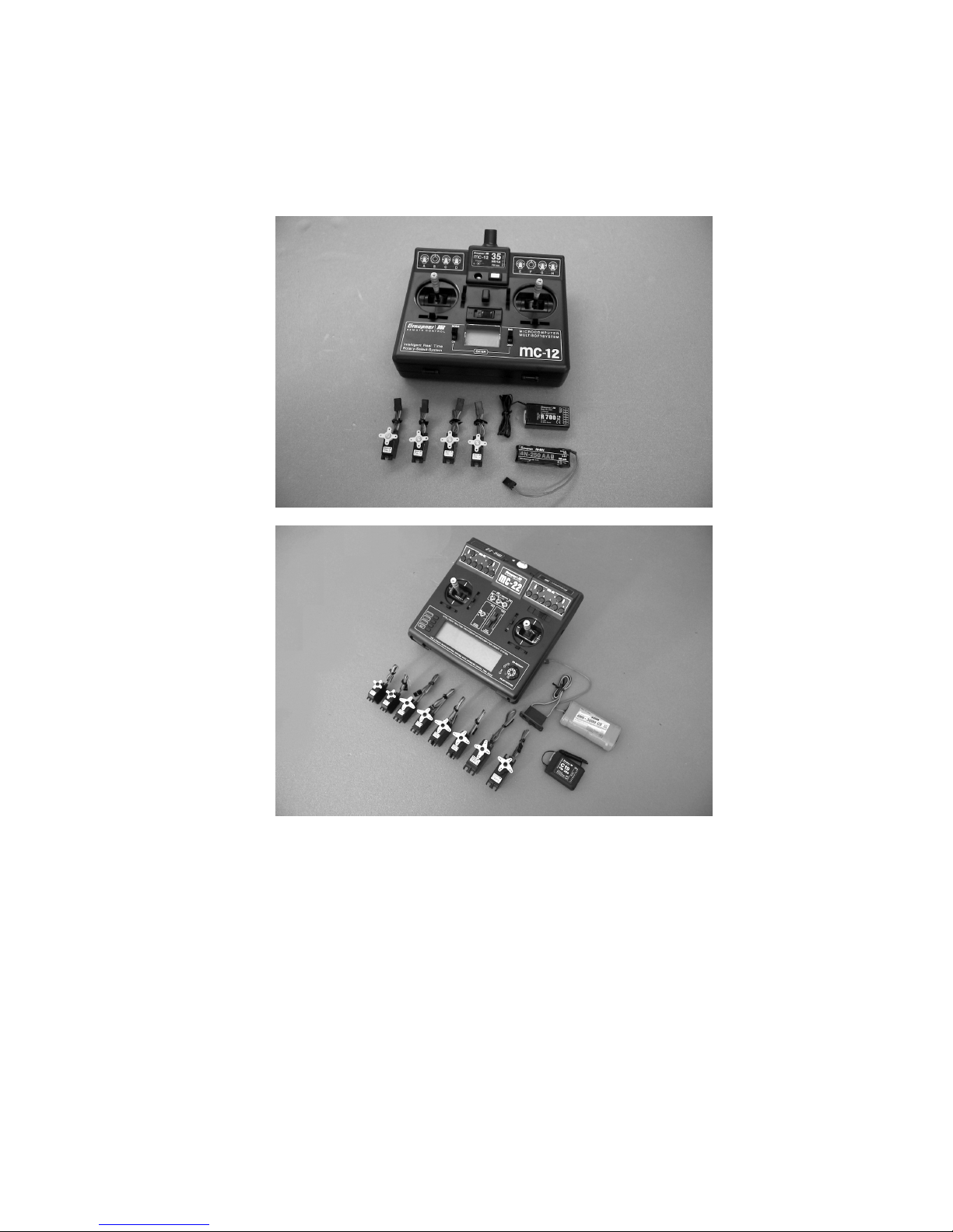
Radio control system
We particularly recommend computer radio control systems ranging from the mc-19
to the mc-24
or
Recommended servos:
Rudder DES 657 BB MG Order No. 7923 1 reqd.
Elevator DES 587 BB MG Order No. 7932 1 reqd.
Ailerons DS 3068 Order No. 5188 2 reqd.
Camber-changing flaps DS 3068 Order No. 5188 2 reqd.
Airbrakes C 351 Order No. 5123.lose 2 reqd.
Aero-tow mechanism DS 8077 Order No. 5149 1 reqd.
Retractable wheel C 713 Order No. 3887 1 reqd.
Select a suitable receiver on the 35 MHz or 2.4 GHz band to suit your system.

GRAUPNER GmbH & Co. KG D-73230 KIRCHHEIM/TECK GERMANY
Modifications reserved. No liability for printing errors. Ident. # 0062067 4/2010
5
Order No. 4135 PRX 3A stabilised receiver power supply 1 reqd.
Servo extension leads required
Order No. 3935.50 for permanent connection to receiver 6 reqd.
Order No. 3935.105 for elevator 1 reqd.
Order No. 3935.105 for ailerons 2 reqd.
Order No. 3935.32 for airbrakes 2 reqd.
Order No. 3935.32 for camber-changing flaps 2 reqd.
Order No. 98516.1 folding ferrite ring for aileron,
flap and airbrake servos 2 reqd.
Order No. 1587 Velcro (hook-and-loop) tape 1 pack
We recommend a receiver battery of at least 3 Ah capacity, which should be properly
prepared before use and maintained during its life, i.e. the pack must be charged and
discharged (cycled) several times before it reaches its full stated capacity.
We deliberately recommend the use of rechargeable batteries for the receiver and
transmitter, as they offer the widest margin of safety in use.
Please see the main GRAUPNER FS catalogue for details of suitable chargers.
Use foam rubber to pack round the receiver.
Assembling the ASW 28
Please don’t start work on the model until you have read through the instructions and
have a clear understanding of the purpose of the various components and the individual stages of construction. If you are not satisfied with the quality of any part,
take it back to your model shop for replacement before modifying it in any way.
These instructions describe the construction of the model including the installation of
the retractable motor, Order No. 6097. If you do not intend to fit a power system, i.e.
you prefer to build the model as a pure glider, you should simply ignore these stages.
The fuselage
Thoroughly sand all the joint areas inside the fuselage until they have a matt appearance (see the note following the Adhesives table).
Before you start construction you have to decide whether to install a retractable
wheel or not. If you are fitting a retractable motor, a retractable wheel is essential.
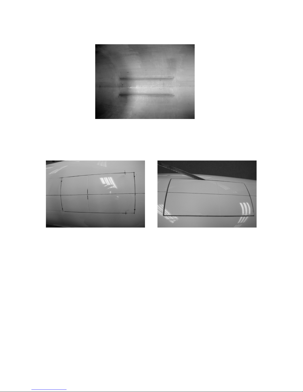
If you intend to complete the ASW 28 as a pure glider, cut the wheel doors out of the
fuselage using a fine-blade piercing saw; the outline of the opening is marked on the
underside of the fuselage.
However, if the model is to be fitted with a retractable motor, the wheel doors need to
be moved forward by about 60 mm, and should be about 110 mm long overall.
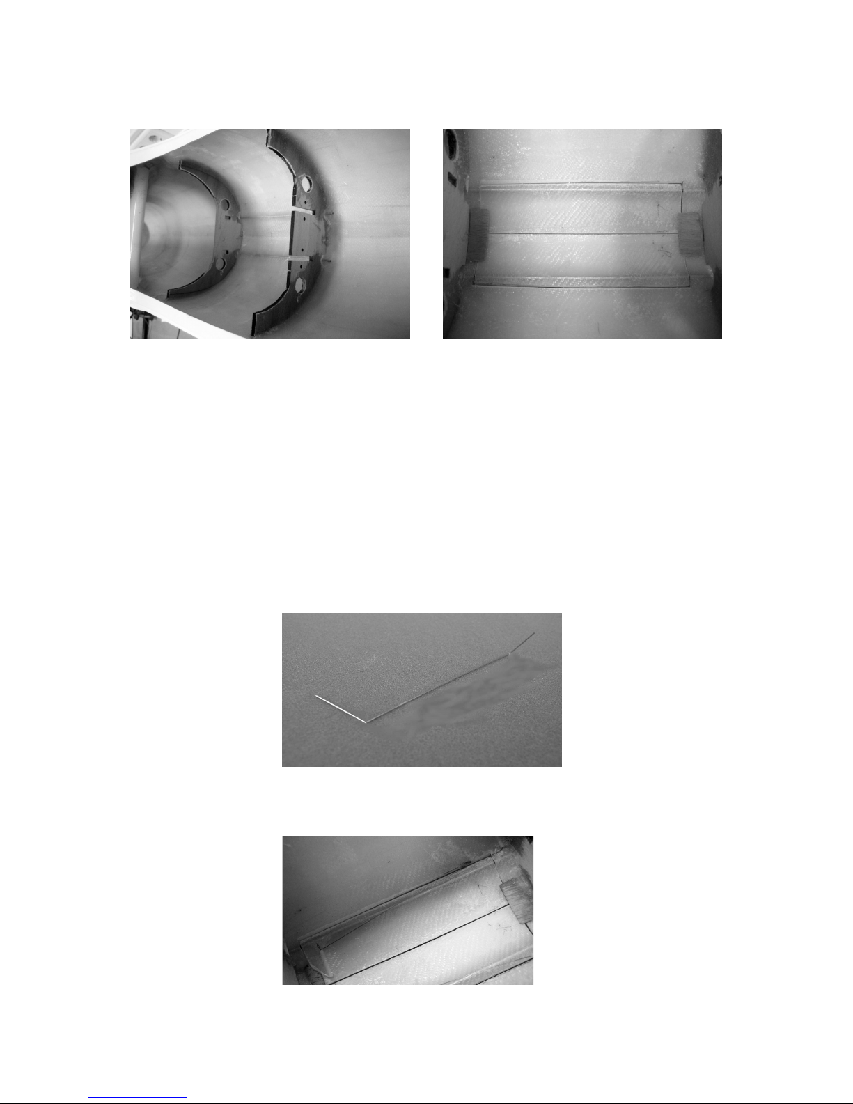
Before cutting out the wheel doors, drill four 1 mm Ø holes on the marked transverse
lines at both ends, spaced about 22 mm from the fuselage centreline. Fit short steel
pins through these holes, projecting on the inside, and place the aluminium tubes
GRAUPNER GmbH & Co. KG D-73230 KIRCHHEIM/TECK GERMANY
Modifications reserved. No liability for printing errors. Ident. # 0062067 4/2010
6
(the wheel door pivot bushes) against them, so that the distance between the tubes
is around 22 mm.
Position the aluminium tubes against the pins on the inside of the fuselage, projecting
by about 15 mm front and rear, and tack them to the floor of the fuselage with a few
drops of cyano. The steel pins can now be withdrawn, and the aluminium tubes fixed
permanently to the fuselage using EPOXY resin and glass cloth. When the resin has
cured, the wheel doors can be sawn out as shown in the photo below.
Lightly sand the edges of the wheel doors. The doors are attached to the fuselage by
means of two 1.5 mm Ø steel rods which are slipped through the aluminium tubes
from the front. Check that the wheel doors open and close smoothly; you may need
to sand back the edges slightly to avoid them fouling the opening.
At this stage the two formers which support the retractable wheel unit can be glued
into the fuselage. Use the outer former shape if you are installing a retractable motor;
the inner former shape is for the glider version. Carefully remove the formers from the
plywood sheets and fit them onto the support lugs of the retract unit at front and rear.
Place this assembly in the fuselage, and align it with the opening in the underside.
With the wheel up, check that the retract unit is central in the fuselage opening. It is
also essential to check that the wheel can extend and retract without fouling the rear
edge of the fuselage opening. When you are confident that all is well, tack the two
formers in the fuselage using a few drops of cyano. Check the system once more,
then glue both formers in the fuselage permanently using epoxy resin and glass
cloth.
GRAUPNER GmbH & Co. KG D-73230 KIRCHHEIM/TECK GERMANY
Modifications reserved. No liability for printing errors. Ident. # 0062067 4/2010
7
To ensure that the two wheel doors close flush with the outside of the fuselage, glue
a small piece of plywood to the inside of the fuselage front and rear, as shown in the
photo above.
Check that the wheel doors still open and close smoothly.
Take care not to glue the wheel doors to the fuselage.
When the glue has set hard, the wheel door closing springs can be installed:
Bend two torsion springs to the shape shown in the photo: one right and one left
(handed pair).
The torsion springs should be about 15 mm shorter than the wheel doors, and the
short ends should be around 15 mm long. Both ends of the torsion springs are fitted
in pieces of plastic tube which are glued to the wheel doors and fuselage as shown.
Do not glue the springs in the plastic sleeves, as you may need to replace them and /
or the wheel doors at some time.
Install the torsion springs as shown in the photo below. Once again, take great care
to avoid gluing the wheel doors to the fuselage accidentally.
GRAUPNER GmbH & Co. KG D-73230 KIRCHHEIM/TECK GERMANY
Modifications reserved. No liability for printing errors. Ident. # 0062067 4/2010
8
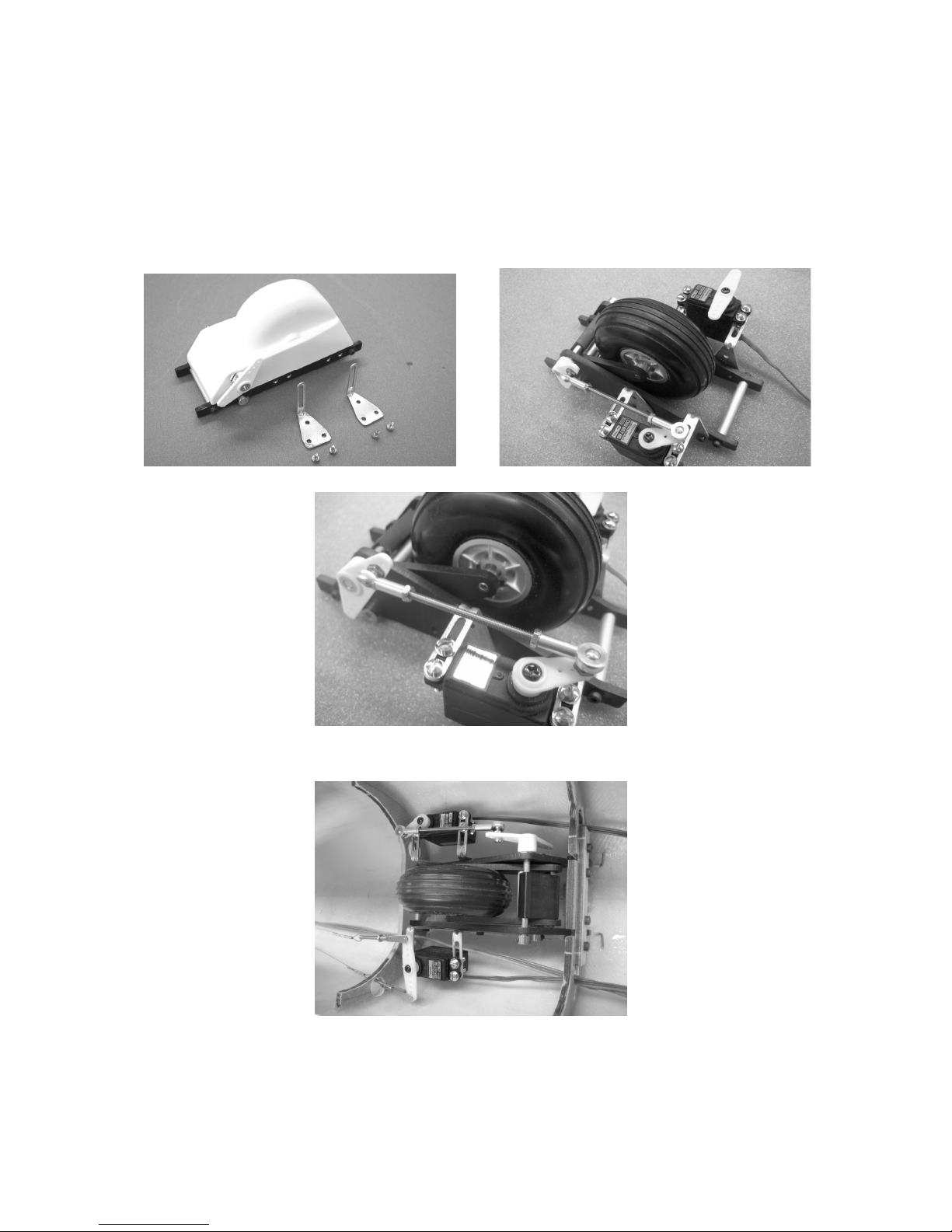
The next step is to mount the rudder servo and the retract servo on the retract unit,
as shown in the photos below.
The retract pushrod is assembled and installed as shown in the photo.
Adjust the retract linkage so that the wheel locks reliably in the extended and retracted states.
Now place the undercarriage unit in the slots in the rear former, and secure it by
screwing the plywood plate in place at the front.
 Loading...