

Page 1
GRAUPNER GmbH & Co. KG D-73230 KIRCHHEIM/TECK GERMANY
Changes reserved! No liability for printing errors ID. no. 0063067 07/2012
1
for Order no. 42125
42135
Instruction Manual
ASH 31 MI
RC Glider and Electric Aircraft
for
Slope Flying, Towing and Electric Flight
A remote control with 6 functions is needed!
This models is not a beginner model and is only
intended for experienced model builders!
The present model is a technically mature design with well-balanced flight
characteristics. The pre-assembly of a number of the individual parts enables a rapid
building process.
Page 2

GRAUPNER GmbH & Co. KG D-73230 KIRCHHEIM/TECK GERMANY
Changes reserved! No liability for printing errors ID. no. 0063067 07/2012
2
Technical data
Wingspan, about 4510 mm
Length about 1785 mm
Wing airfoil TA06/11
Tailplane airfoil NACA 009
Total surface area about 79 dm²
Flying weight depending on
equipment from about 5500 g Glider
7000 g Electric
Center of gravity about 95 mm behind the leading edge measured on the left and
right of the hull.
Longitudinal dihedral about 1°
Notices for the construction of the model
Before building of the model, be sure to study the manual from start to finish. Be
aware of the potential dangers associated with the use of tools.
Clean all oily residue off of the surfaces to be adhered prior to adhering them. This
can be achieved with light sanding and a non-oily cleanser. Prior to adhering parts,
make sure to roughen the corresponding surfaces (especially with GRP hulls)
carefully using a fine sandpaper and be sure to thoroughly remove all grease and oil
using acetone, etc. Otherwise, sufficient adhesion cannot be guaranteed.
Required tool for the construction of ASH 31 MI
Pencil (hardness HB), all-purpose pen, geometry triangle, as well as a measuring
tape or meter stick, household scissors, a thin and sharp knife - such as a balsa
knife Order No. 980, small electric drill, various spiral drills, Allen wrenches, injection
syringe Order No. 729.3.
Adhesion of materials
The table below shows some examples for adhesive bonds.
It should not be considered exhaustive.
Material Adhesion example Adhesive
Order No.
GRP with Hull with UHU plus endfest 300
Plywood Landing gear ribs Order no. 950.43
GRP with Hull with UHU plus endfest 300
Aluminum F tow coupling Order no. 950.43
Areas of the hull without pull-away material which are to be adhered must be sanded
using a fine grain sandpaper in order to remove any remaining release agent. Wipe
away sanding dust. In the process, the shiny surface of the hull must always become
matte, otherwise a good adhesion of the adhesive with the hull cannot be assured.
To join the individual parts with one another, make sure to following the
corresponding instructions for use provided on the adhesive. Additional adhesives
can be found in the FS catalog.
Page 3
GRAUPNER GmbH & Co. KG D-73230 KIRCHHEIM/TECK GERMANY
Changes reserved! No liability for printing errors ID. no. 0063067 07/2012
3
When using adhesives with solvents, make sure that the room is well-ventilated.
Observe the manufacturer's notices.
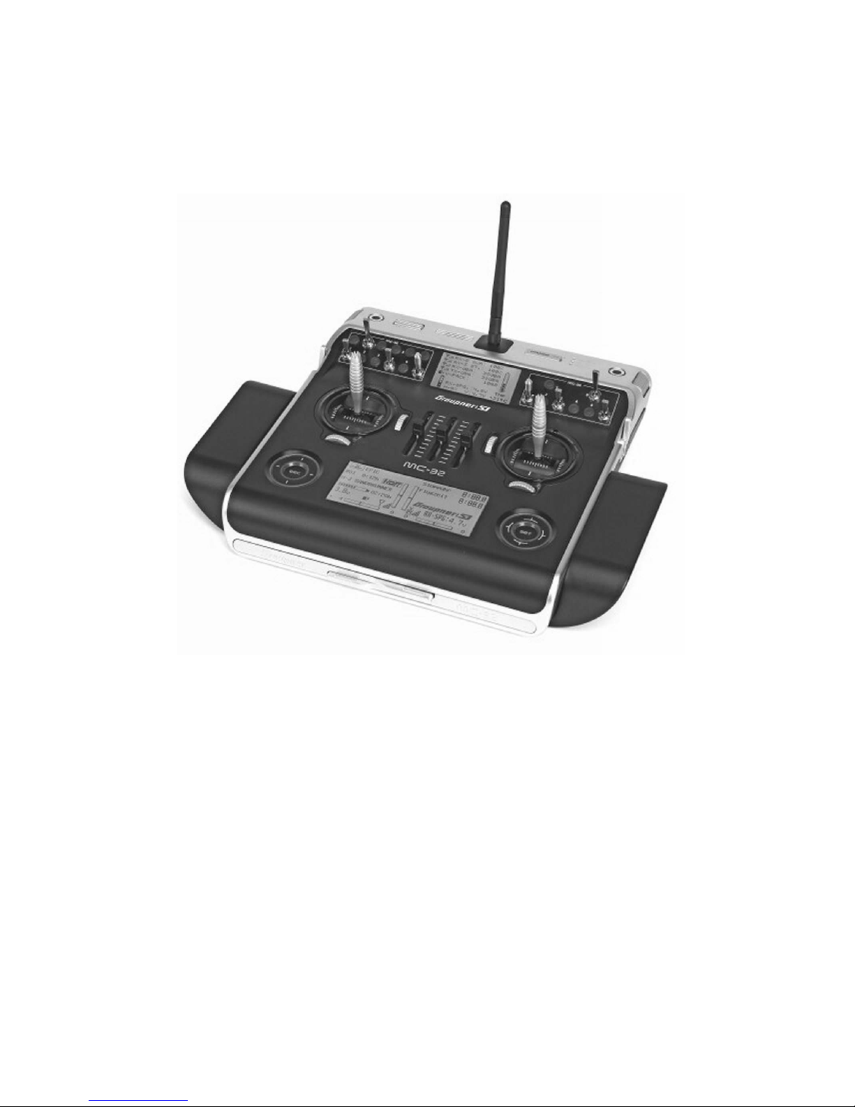
Remote control system
Strongly recommended: Computer system mc-32
Recommended servos:
Rudder DES 678 BB,MG Order no. 7943 1 unit
Elevator DS 3288 BB,MG Order no. 5187 1 unit
Outer aileron DS 3288 BB,MG Order no. 5187 2 units
Center aileron DS 3288 BB,MG Order no. 5187 2 units
Camber-changing flap DS 3288 BB,MG Order no. 5187 2 units
Landing flap DES 678 BB,MG Order no. 7943 2 units
F tow coupling DES 678 BB,MG Order no. 7943 1 unit
Retractable landing gear HBS 760 BB,MG Order no. 7985 1 unit
Wheel brake HBS 760 BB,MG Order no. 7985 1 unit
For the connection of the servos to the receiver
6x Servo voltage regulator PS 5.9 volt Order no. 4197
For battery connection cable 4x Order no. 3941.6
1x Order no. 2985.D
Required servo extension cables
Order no. 3935.180 For elevator 1 unit
Order no. 3935.180 For rudder 1 unit
Order no. 3935.75 For connection to the receiver 8 units
Page 4
GRAUPNER GmbH & Co. KG D-73230 KIRCHHEIM/TECK GERMANY
Changes reserved! No liability for printing errors ID. no. 0063067 07/2012
4
Order no. 3935.65 For connection to the receiver 2 units
Order No. 1587-20 Hook-and-loop cable tie 1 package
As a receiver battery, we recommend a two-cell LiPo battery with a capacity of at
least 5 Ah, e.g. Order no. 99013, which must always be well-maintained before and
after flight.
Rechargeable batteries are recommended for the receiver and transmitter, because
they offer the greatest safety.
See the FS catalog for the corresponding charger.
Foam rubber for the bearing of the receiver
Hook and loop tape Order no. 3368.1 for the fastening of the receiver
Hook-and-loop cable tie Order no. 1587 for the fastening of the drive battery
Required accessories
Retractable landing gear Order no. 1137
Cockpit equipment Order no. 1055.1
Joystick set Order no. 1064.2
Assembly of the ASH 31 MI
Only the assembly of the electric version is described in the assembly manual.
Obviously the work pertaining to the extend/retract drive is omitted for the glider
version.
Only begin with the assembly once you are familiar with the components and
individual building stages. If there are grounds for objection of a component, inform
your specialist dealer prior to beginning with the construction.
The hull
All parts of the hull to be adhered must be sanded with sandpaper until the area to be
adhered becomes matte (also refer to the information in the adhesives table).
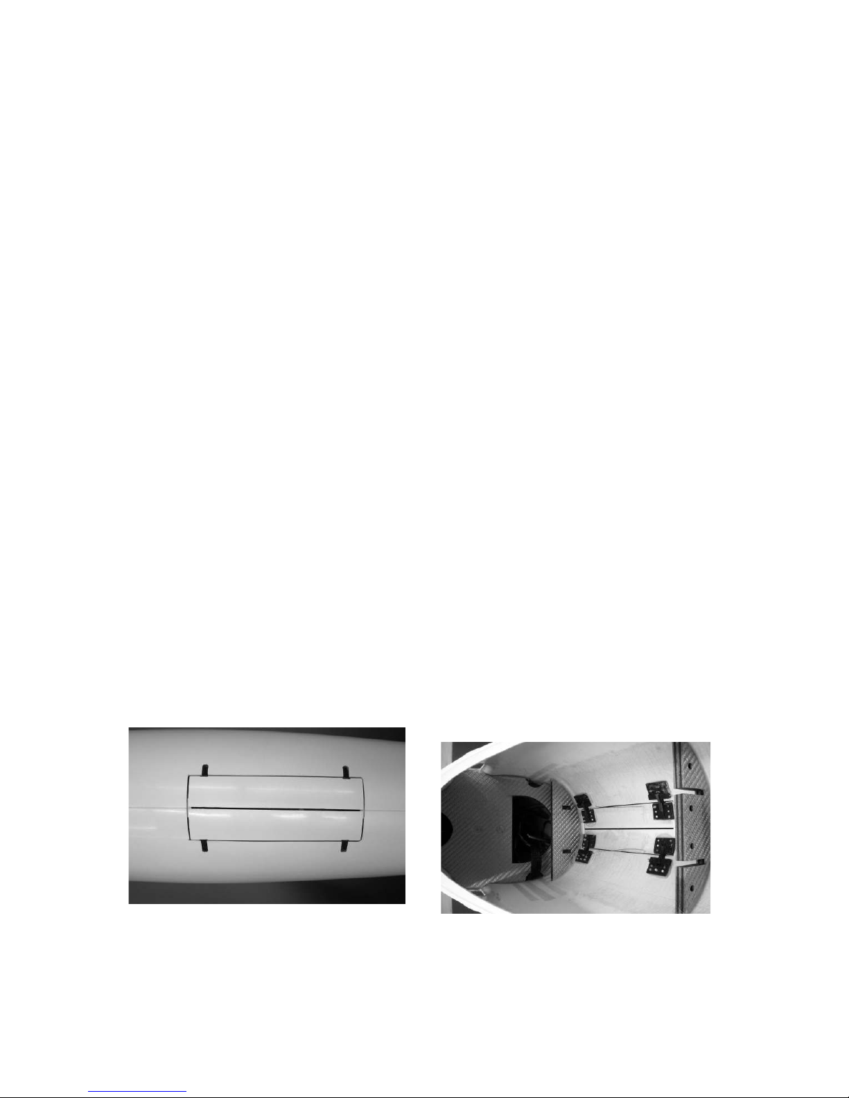
Remove the pull-away material on the adhesion areas of the hinge joints for the
closing flaps of the landing gear and extend/retract drive. Attach the hinges at the
flaps and hull as shown in the photos. In the process, make sure that the gap
between the hull and flaps is the same size all the way around.
After the adhesive hardens, it should
adhered with a strip of glass fabric leaving a slight protrusion for the hinged joints.
Torsional springs must be bent from the accompanying Ø 0.6 mm steel wire to close
the flaps and must be adhered as shown in the photo.
Page 5
GRAUPNER GmbH & Co. KG D-73230 KIRCHHEIM/TECK GERMANY
Changes reserved! No liability for printing errors ID. no. 0063067 07/2012
5
As you can see in the photos, stops in the hull are adhered at the ends of
the flaps so that the flaps end flush with the outer contour of the hull.
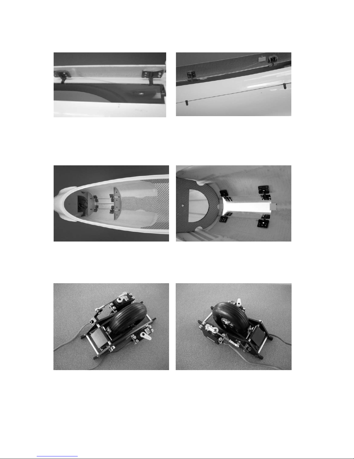
The ribs for the extend/retract drive and the retractable landing gear are only
attached in the hull and still have to be adhered with 24-hour epoxy resin.
The retractable landing gear and the extend/retract drive are mounted in the hull after
the adhesive has hardened.
Please follow the instructions accompanying the landing gear for the assembly of the
retractable landing gear. Here are a few photos showing how the retractable landing
gear is assembled.
Now insert the retractable landing gear into both ribs and fasten using the Allen
screws and the holder bracket.
The extend/retract drive is screwed onto the rib with the two screws.
Page 6
GRAUPNER GmbH & Co. KG D-73230 KIRCHHEIM/TECK GERMANY
Changes reserved! No liability for printing errors ID. no. 0063067 07/2012
6
The screw must be secured against loosening with UHU thread-lock.
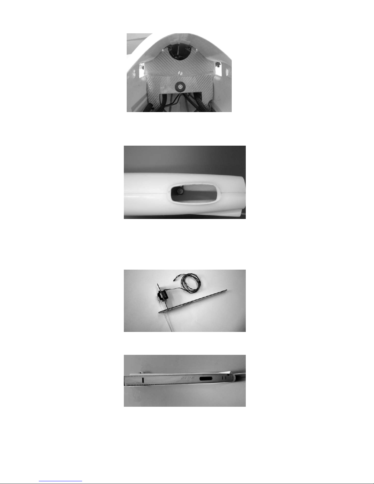
For the assembly of the tail wheel and the rudder servo, the recess at the hull end
must be cut out and filed down to match the tail wheel.
Adhere the fin end and rudder servo board together.
Extend the rudder servo connection cable with the appropriate extension cable.
Secure the plug connection against loosening. Using rubber bushes, rivets and the
accompanying screws, fasten the servo to the board.
Attach the rudder linkage to the servo lever as shown in the photo.
Now the fin end can be adhered. In the process, make sure that it is recessed from
the edge approx. 13 mm at the bottom and approx. 11 mm at the top.
Page 7
GRAUPNER GmbH & Co. KG D-73230 KIRCHHEIM/TECK GERMANY
Changes reserved! No liability for printing errors ID. no. 0063067 07/2012
7
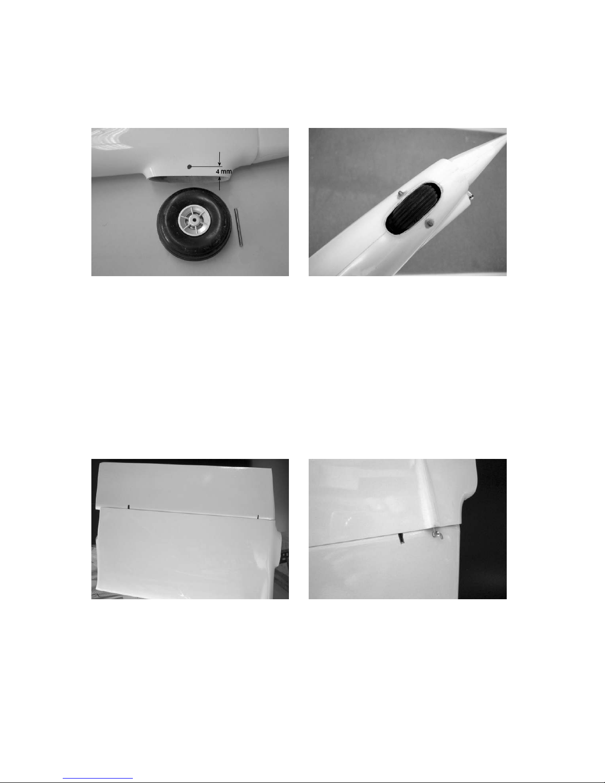
Drill a Ø 2 mm hole on the left and right side of the hull for the bearing shaft of the tail
wheel corresponding to the specifications in the photo. Mount the tail wheel together
with the bearing shaft in the hull. Adhere the bearing shaft on the right and left sides
of the inside of the hull.
Check whether the rudder can move equally far to the left and right. Remove the
rudder, apply adhesive to the GRP bearings and re-insert the rudder and bearings in
the same position. Secure the rudder against slipping with adhesive strips until the
adhesive hardens. After the adhesive hardens, mark the position of the control arm.
Drill a Ø 4 mm hole in the rudder. Attach the steering linkage in the servo lever and
with the Z-bending in the control arm. Check the correct length of the linkage with the
servo mounted in the rudder center position and the control arm connected. Now
adhere the control arm to the rudder with adhesive.
Page 8

GRAUPNER GmbH & Co. KG D-73230 KIRCHHEIM/TECK GERMANY
Changes reserved! No liability for printing errors ID. no. 0063067 07/2012
8
Adhere the boards for the receiver and drive battery fastening in the hull as shown in
the two photos.
In the following photo you can see the installation of the voltage regulator PS 5.9 volt.
The cockpit canopy
The cockpit canopy frame must be adapted to the hull. In other words, it must sit
back in the outer hull contour an equal distance all the way around corresponding to
the size of the cockpit canopy. The front fastening of the frame is achieved with a
GRP tongue, which is adhered to the frame so that it protrudes approx. 15 mm.
For the rear fastening of the frame, a Ø 2 mm hole is drilled through the frame and
hull approx. 4 mm below the upper edge of the hull while the frame is in position.
Page 9

GRAUPNER GmbH & Co. KG D-73230 KIRCHHEIM/TECK GERMANY
Changes reserved! No liability for printing errors ID. no. 0063067 07/2012
9
The locking of the cockpit canopy is carried out with a Ø 2 mm steel wire guided in a
plastic tube. This tube is attached with the locking pin pushed in. As described with
the hinge joints of the flaps, the tube should be adhered to the hull using a glass
fabric strip. Cut out the cockpit canopy along the mark, leaving a slight protrusion and
adapt it to the canopy frame/ hull.
Before adhering the cockpit canopy on the frame, it must be painted as desired The
cockpit instruments, etc. must also be adhered.
Now the cockpit canopy can be adhered. For this purpose, fasten the frame on the
hull by fastening the front to the hull with the GRP tongue and the rear with a locking
pin. The frame is adhered with the cockpit canopy using UHU ALL-PURPOSE
ADHESIVE Kraft Ord. No. 1096. These are transparent contact adhesives. Before
the adhesion, the hull seam must be applied to the cockpit canopy.
Apply adhesive all the way around on the frame, then position the cockpit canopy so
that the hull seam matches the markings and then remove it again. After the
adhesive has ventilated, place the cockpit canopy in its final position again, line it up
with the markings and press down all the way around. Then the edge of the cockpit
canopy can be painted.
The tailplane assembly
Corresponding to the specified measurement in the photo, cut a slot in the elevator
which extends to the upper covering The GRP control arm must be adhered so that
the attachment point of the steering linkage and the turning point of the rudder match.
The elevator servo is shrink-fitted in shrink hose and adhered in the opening in the
tailplane so that the steering linkage (M2 threaded rod with double elbow with M2
clevis and M2 counter nut) forms a right angle with the turning axis of the elevator.
Page 10

GRAUPNER GmbH & Co. KG D-73230 KIRCHHEIM/TECK GERMANY
Changes reserved! No liability for printing errors ID. no. 0063067 07/2012
10
The cable on the servo can be left for the connection of the servo to the receiver, or it
can be soldered to a G 6 plug (as shown in the photo), which is adhered in the
recess. In parallel, the counterpiece must be adhered to the elevator support in the
hull. Extreme care must be taken in the process in order to ensure that the plug
connection does not come loose again. For the fastening of the tail on the hull, the
two fastening holes must be melted open using a hot soldering iron.
The wings
Mount the control arms as shown in the photos below. Adjust the length of the
linkage. The steering linkage for the rudders is comprised of an M2 clevis and M2
threaded rod, which has a double bend for attachment to the servo arm (Bending
pliers Order no. 5732). Cut or file slots in the rudders up to the leading edge of the
rudders in order to accommodate the control arms. In doing so, make sure that the
control arms can be pushed in / adhered to the upper covering.
Important: The adhesive bonds of the
control arms with the rudders should be made with 24-hour epoxy resin.
For the installation of the servo, scrape out a recess in the hard foam core up to the
upper covering. Now apply adhesive and adhere the servo mounting frame.
The servos for the landing flaps are also
Page 11

GRAUPNER GmbH & Co. KG D-73230 KIRCHHEIM/TECK GERMANY
Changes reserved! No liability for printing errors ID. no. 0063067 07/2012
11
fastened in the wing halves. The steering linkage is attached with a double elbow on
the servo lever; see photo. To mark the length of the steering linkage, it must be
attached to the lever in the landing flap. For this purpose, a threaded bush is
soldered onto the end of the linkage and fitted with an M2 nut and an M2 clevis.
When marking the length of the linkage, move the servo to the retracted position. For
this purpose, briefly turn on the RC system. Attach the linkage in the servo lever and
adhere the servo.
If the servos are adhered in the recesses, they must first be fitted in shrink hose. The
shrink hose must be roughened prior to adhering.
The servo covers are fastened in the recesses with the accompanying countersunk
sheet metal screws. Pre-drill Ø 1.5 mm holes in the covers and lower the screws in
the covers accordingly.
After the adhesive hardens, the landing flap covers are adjusted and adhered. In
doing so, make sure that there is a gap of approx. 0.5 mm
the entire way around. The covers should be secured with an adhesive strip to
prevent slipping and to assure a flush fit with the profile contour until the adhesive
hardens. Now move the landing flap out, remove the upper brake plate and cover the
wood with adhesive film.
Before adhering the torsion pins in the root ribs, insert the two wing halves into the
hull using the wing connector in order to check the fit.
Page 12

GRAUPNER GmbH & Co. KG D-73230 KIRCHHEIM/TECK GERMANY
Changes reserved! No liability for printing errors ID. no. 0063067 07/2012
12
Before adhering the torsion pins, they must be roughened at the points to be
adhered. When adhering, approx. 15 mm should protrude from the root ribs.
As is shown in the photo, the servo connection cables can be run together using a G
6 plug connector. Attach the wiring harness in the hull from the receiver to the plug
connection. In the process, the plus and minus leads can be run together. Then they
can be soldered to the respective outside contacts. Then there is still a contact
available for the impulse lines.
Important: The correct polarity must be absolutely assured.
The outer wing
First adhere the anti-twist devices in the root ribs of the insertable wings as described
for the inner wings; these should protrude approx. 10 mm from the root ribs.
Tip: Place a layer of household plastic foil between the wing sections and lightly
grease the pin (not on the side to be adhered). In doing so, you prevent the wing
sections from sticking together and/or prevent the pin from adhering to the sleeve
with any escaping resin.
Page 13

GRAUPNER GmbH & Co. KG D-73230 KIRCHHEIM/TECK GERMANY
Changes reserved! No liability for printing errors ID. no. 0063067 07/2012
13
To secure the outer wing to the inner wing, engage the plastic locking devices in the
corresponding holes.
After the adhesive hardens, the multi-lock studs are adhered in the outer wing
sections. For this purpose, adhere Tesafilm over the area around the two eyes in the
wing center section and cut the film crosswise over the eyes. Now insert both studs in
the eyes. The outer wing sections are also protected with Tesafilm in the area around
the holes for the studs and are also opened. The holes in the outer wings are filled
with a somewhat hardened resin and the plastic part is pushed in until the edge ends
flush with the root rib. After the hardening of the adhesive, fit the counterpiece in the
hole in the inner wing, apply adhesive and press the two wing parts together flushly
with the CFRP connector and the torsion pins, then fix in place with adhesive tape
until the adhesive hardens. After the adhesive hardens, the excess resin can be
removed together with the adhesive tape.
The winglets are then each inserted on the outer wing with two Ø 3mm and Ø 2mm
steel pins. The winglets are secured with strips of adhesive tape.
Page 14

GRAUPNER GmbH & Co. KG D-73230 KIRCHHEIM/TECK GERMANY
Changes reserved! No liability for printing errors ID. no. 0063067 07/2012
14
Assembly of the ASH 31 MI
Insert the wing halves on the hull using the mating so that the servo connection
cables can be connected; then push both wing halves all the way onto the hull so that
the root ribs are against the hull; insert the four anti-twist devices in the holes of the
profile recesses of the hull. The two wing halves are secured by screwing in the
locking screws with washers from the inside of the hull.
Fit the outer wing on the inner wing using the GRP round bar and push together until
the plastic locking devices engage.
Fit the winglets and secure them using strips of adhesive tape.
Fasten the tailplane on the hull using the two M5 Allen screws. Only tighten the
screws until the tailplane fits against the profile recess without play.
Fasten the cockpit canopy on the hull using the GRP tongue in the front and using
the steel pin in the back.
Balancing the ASH 31 MI
Support the model to the left and right of the hull approx. 95 mm behind the leading
edge of the wings. If the center of gravity is correctly positioned, the model stop
rocking back and forth at a horizontal attitude or the hull nose should point slightly
downward. If necessary, the center of gravity can be moved by shifting the position of
the battery or attaching trim weight. Before the initial flight, all rudders must be moved
precisely to the center position (zero position) with the transmitter trim adjustment in
the middle.
Page 15

GRAUPNER GmbH & Co. KG D-73230 KIRCHHEIM/TECK GERMANY
Changes reserved! No liability for printing errors ID. no. 0063067 07/2012
15
ASH 31 MI rudder throws
Rudder +/- 45 mm
Elevator +/- 8 mm
Aileron 15 mm upward
5 mm down
Center aileron 16 mm upward
6 mm downward
Camber-changing flap 5 mm upward
4 mm downward
All rudders move for with the aileron throw. With the specified throws the outer
aileron have an equal throw to the inner camber-changing flaps.
Exponential value for aileron 33 %
for elevator 26 %
Flap position for thermal flight:
Camber-changing flap positive downward 2 mm
Center aileron positive downward 1.5 mm
Aileron positive downward 1.5 mm
Flap position for high-speed flight:
Camber-changing flap negative upward 2 mm
Center aileron negative upward 1.5 mm
Aileron negative upward 1 mm
Flap position for landing:
Landing flaps fully thrown
Camber-changing flap 26 mm downward
Center aileron 14 mm upward
Aileron remain in the neutral position
Elevator 2 mm
An exponential value 45% has been proven to be successful for ailerons and
elevators.
The specified throws are only recommendations, which must be adapted to your
individual piloting habits.
Important:
With the assembly of the linkage, it must be ensured that they can move easily over
their entire control path - including trim adjustment - and are not mechanically limited
in any way.
When moving the joystick to the right, the rudder must throw to the right (left/left).
When moving the elevator joystick back - in other words, towards your stomach - the
rudder must throw upward (forward = down).
When moving the aileron joystick to the right, the right aileron must move throw
upward and the left downward. The landing flaps are actuated with the nonneutralizing joystick. Moving the joystick all the way forward retracts the landing flaps;
moving the joystick all the way back extends the flaps.
Page 16

GRAUPNER GmbH & Co. KG D-73230 KIRCHHEIM/TECK GERMANY
Changes reserved! No liability for printing errors ID. no. 0063067 07/2012
16
Do not extend the landing flaps too quickly and too far; they operate effectively.
Extending the flaps approx. 5 mm is sufficient for the landing approach.
Now all that remains is to have fun flying your ASH 31 MI. We hope you enjoy!
Your team !
Part
no.
Designation
Qty.
Material
Dimensions
1 Hull 1 GRP Finished part
2 Drive system flaps 1 pair GRP Finished part
3 Landing gear flaps 1 pair GRP Finished part
4 Hinged joints 8 plastic Finished part
5 Drive system torsion
spring
2 steel Ø 0.6
6 Landing gear torsion
spring
2 steel Ø 0.3
7 Torsion spring mount 8 plastic Ø 1.85/0.9
8 Wheel 1 plastic Ø 30
9 Wheel axle 1 Steel Ø 3x30
10 GRP bearing 2 GRP Finished part
11 Rudder 1 Balsa/film Finished part
12 Bearing pin 1 CFRP Ø 2x400
13 Control arm - rudder 1 Aluminum finished part Hole Ø 1.6
14 countersunk-head screw 2 Steel M5x12
15 Allen screw 4 Steel M5x15
16 Self-tapping screw 1 Steel M5
17 Cockpit canopy frame 1 GRP Finished part
18 cockpit canopy 1 Plastic Finished part
19 Guide tube 1 Plastic Ø 3.2/2.2x80
20 Rear lock 1 Steel Ø 2x120
21 Front lock 1 GRP 12x2x100
22 Tailplane 1 Sandwich Finished part
23 Control arm 1 GRP Finished part
24 Steering linkage 1 Steel M2x100
25 nut 1 Steel M2
26 Clevis 1 Steel M2 finished part
27 Allen screw 2 Steel M5x25
28 Right wing 1 Sandwich Finished part
29 Left wing 1 Sandwich Finished part
30 Torsion pin 4 Steel Ø 4x50
31 Anchor nut 2 Steel M5
32 Push pin (multi-lock) 2 Plastic Finished part
33 Push eye (multi-lock) 2 Plastic Finished part
34 Torsion pin 4 Steel Ø 3x30
35 GRP connector 2 GRP Ø10x180
36 Spar connector 1 CFRP Finished part
37 Threaded bush 2 Steel/nick. M2
38 nut 2 Steel M2
Page 17

GRAUPNER GmbH & Co. KG D-73230 KIRCHHEIM/TECK GERMANY
Changes reserved! No liability for printing errors ID. no. 0063067 07/2012
17
39 Clevis 8 Steel M2
40 Control arm 6 GRP Finished part
41 Threaded rod 8 Steel M2
42 Winglet 2 GRP Finished part
43 Fastening pin 2 Steel Ø 3x30
44 Fastening pin 2 Steel Øx30
Page 18

GRAUPNER GmbH & Co. KG D-73230 KIRCHHEIM/TECK GERMANY
Changes reserved! No liability for printing errors ID. no. 0063067 07/2012
18
The complete operating and assembly instructions must be read carefully
before attempting to put the model into operation for the first time. You are
solely responsible for the safe operation of your RC model aircraft. Youths who
perform assembly and/or operate the model must be responsibly supervised
by an adult who is familiar with the circumstances and potential hazards
involved with RC model aircraft.
Questions about the safe operation of RC aircraft models will gladly be
answered by dealers.
Remote controlled aircraft models are quite sophisticated, dangerous objects.
They demand a great deal of expertise, skill and sense of responsibility.
From a legal point of view, a model aircraft is an aircraft and, as such, subject
to respective laws that must absolutely be observed. The pamphlet »Model
aviation law"«, order no. 8034.02, presents a summary of these laws. This
pamphlet can also be reviewed at dealerships. Furthermore, compliance with
the telecommunications regulations related to remote control systems is
required. Appropriate notices can be found in the operating instructions for
your remote control system.
Only those parts included in the kit as well as those original Graupner
accessories and replacement parts which we expressly recommend may be
used. Even if only one component in the drive unit is changed, safe operation
is no longer warranted and any rights under the guarantee are voided.
Always use only the fitting, polarized connectors.
Avoid short circuit conditions and reverse polarity.
The high energy level of NiMH batteries present explosion and fire hazards.
A RC aircraft model can only be functional and meet expectations when it has
been carefully built according to the assembly instructions. Only cautious,
considered handling during operation of the model will prevent personal
injuries and property damage. No one would get into a glider and – without any
advance training – attempt to fly it. Even flying model aircraft requires practice.
However, the manufacturer has no possibility to influence the assembly and
operation of a RC aircraft model. This is why emphatic notification is herewith
made about the hazards, and all liability for these is expressly rejected.
Please address these issues with an experienced model pilot, a club or a model
aircraft school. We also refer you to dealerships and relevant trade
publications. The optimal situation is to fly from an approved model airfield as
a club member.
Adhesives and paints contain solvents which, under some circumstances, can
be harmful to one's health. It is therefore imperative that the manufacturer's
respective notices and warnings are observed.
The operator must be in full possession of complete physical and mental
facilities. As with driving an automobile, operating a model aircraft under the
influence of alcohol or drugs is not allowed.
Page 19

GRAUPNER GmbH & Co. KG D-73230 KIRCHHEIM/TECK GERMANY
Changes reserved! No liability for printing errors ID. no. 0063067 07/2012
19
Inform all persons passing by or watching about the hazards associated with
your model before you start it.
Always keep the necessary safe distance between the flying model and
persons or objects; never execute low flying passes over or toward other
persons!
Model flying activity may only be pursued when outdoor temperatures are
between -5 °C and +35 °C. Temperatures outside this range can lead to
changes, e.g. rechargeable battery capacity, material characteristics and
inadequate adhesive bonds.
Every model pilot is to behave such that public safety and order (in particular
other persons and property) as well as other model flying activities in the area
are neither endangered nor disturbed.
Never fly the model aircraft in the vicinity of high-voltage transmission lines,
industrial premises, residential areas, public streets, plazas, school yards,
parks or playgrounds and the like.
Warnings must absolutely be observed. They point out situations and
activities which, if disregarded, can lead to severe injuries – in extreme cases
even to lethal injuries or permanent disabilities.
Therefore, check the model and all of its attached parts (e.g. RC parts, control
arms, etc.) for secure seating and possible damage before every use. The
model may only be put into operation after all defects have been corrected.
Ensure that your footing is stable when you hold the model in your hand. Wear
appropriate footwear, such as tennis shoes.
Check that the transmitter frequency to be used is free. Only then switch on
the transmitter! Radio frequency interference caused by unknown sources can
occur anytime without warning! The model is then out of control and
unpredictable! Do not leave the remote control system unattended, this
prevents unauthorized third-parties from handling the system.
The model's flying attitude must always be explicitly recognizable during the
entire flight in order to ensure secure control and maneuvers. If functional
impairments or disturbances become evident during a flight, a landing must
be initiated immediately for reasons of safety. You must always avoid other
aircraft. The take-off/landing strip must be free of persons and other
obstacles.
Always ensure the batteries are fully charged as otherwise the flawless
operation of the RC system cannot be assured.
Never use batteries which have been overheated, become defective or are
damaged. The battery manufacturer's usage instructions must always be
followed.
Page 20

GRAUPNER GmbH & Co. KG D-73230 KIRCHHEIM/TECK GERMANY
Changes reserved! No liability for printing errors ID. no. 0063067 07/2012
20
Prior to every flight, check the entire RC system as well as the model aircraft
for full functionality and range.
Switch the transmitter on first and then the receiver system. In reverse order
upon shutdown, be sure to switch off the receiver first and only then switch
off the transmitter.
Check that the aircraft's control surfaces move in the directions they should
with respect to movement of the joystick.
After use, take all batteries out of the model and store it only in a discharged
state (approx. 0.9 V per cell), out of the reach of children, in an environment
having a temperature of between about + 5 C to + 25 C.
These notices are intended to call attention to the diverse hazards that can
arise from improper and irresponsible handling. Proper, conscientious model
aircraft flight is a creative, enlightening, refreshing recreational activity.
Notices for the construction of and flying with ASH 31 MI
Before the construction is begun:
RC parts and rudder linkages are installed during the assembly in accordance with
the construction stages. Installation at a later time is only possible with great difficult
or is not possible at all.
When purchasing a remote control system, be sure its transmitter and receiver are
suitable for aircraft models, that they are certified by telecommunications
authorities and that they have a test certification number.
The frequency bands allocated to remote control are also used by other types of
radio transmissions and high frequency devices. Therefore no protection against
interference can be guaranteed for devices using these frequency bands.
For additional information on this topic, please contact your local
telecommunications authorities or your model building specialist dealer.
During the construction phase
Observe the safety and handling instructions of the manufacturer when working with
adhesives and solvents. Some adhesives and solvents can cause harm to the health
and material damage if they are not used properly. Return any remaining adhesive
and paint to your specialist dealer or drop it off at a waste disposal center.
Be aware that the balsa knife is sharp and pins are pointy and can easily cause
injuries.
Make sure that children do not have access to tools, adhesives or paints.
A generously sized work surface is very advantageous for all types of handicraft
work.
Enlist the help of experienced model builders for difficult steps
if you have little experience in model construction.
About the flight
Never fly the ASH 31 MI in nature reserves or landscape protection areas. Have
consideration for the animals and plants living there.
Trees and bushes are places where birds breed, nest and live.
Page 21

GRAUPNER GmbH & Co. KG D-73230 KIRCHHEIM/TECK GERMANY
Changes reserved! No liability for printing errors ID. no. 0063067 07/2012
21
Important safety notices
This is a construction set that – together with appropriate accessories – can become
a functional RC model. GRAUPNER cannot monitor adherence to the assembly and
operating instructions for the model nor can GRAUPNER supervise the installation,
operation or maintenance of the model and its components. Therefore GRAUPNER
accepts no liability whatsoever for losses, damage or costs that arise from improper
operation, improper behavior or which are associated with same in any manner.
Unless mandated by prevailing law, the obligation of the GRAUPNER company to
provide damage compensation arising from the use of the model, regardless of the
grounds, is excluded (this exclusion includes personal injury, death, damage to
buildings or structures as well as sales and business losses, consequential damage
for business interruption or other direct and indirect consequential damages).
Total liability under all circumstances and in each case is limited to the amount
actually paid for this model.
The commissioning and operation of the model is solely at the risk of the operator.
Only cautious, considered handling during operation of the model will prevent
personal injuries and property damage.
If this is not the case, obtain special liability insurance coverage for RC
models.
These safety instructions must be kept and, if the model is sold, must be
passed on the purchaser.
Manufacturer declaration:
If there should be an evident material or processing defect in one of the objects
marketed in the Federal Republic of Germany and purchased by a consumer (§ 13
BGB) we, the company Graupner GmbH & Co KG, D 73230 Kirchheim/Teck, accept
responsibility for eliminating the object's defect within the scope as specified below.
The rights acquired through this manufacturer declaration cannot be asserted by the
consumer when the object's usage impairment is due to natural wear, use under
competitive conditions, improper usage (including improper installation), or external
causes.
This manufacturer declaration leaves the legal or contractual provisions for defect
claims and the consumer's rights in the purchase contract with respect to the seller
(dealer) unaffected.
Scope of guarantee performance
In the event of a guarantee claim, we reserve the right to choose between a repair or
the replacement of defective goods. Further reaching claims, in particular claims for
compensation of costs in conjunction with the defect (e.g. assembly/disassembly
costs) and remuneration for consequential damages – when legally permitted – are
excluded. Claims based on legal regulations, in particular those associated with
product liability law, are unaffected by this.
Prerequisite to guarantee performance
Page 22

GRAUPNER GmbH & Co. KG D-73230 KIRCHHEIM/TECK GERMANY
Changes reserved! No liability for printing errors ID. no. 0063067 07/2012
22
The purchaser must assert claim for guarantee performance in writing, which is to be
accompanied by the original purchase receipt (e.g. invoice, receipt, delivery note)
and this guarantee card. The purchaser must also return the defective goods to the
above address at his/her own cost.
The purchaser is to state in the claim the nature of the material or processing defect
or the defect's symptoms specifically enough that a review of our guarantee
obligation is possible.
The transportation of the object from purchaser to us as well as return transportation
is at the risk of the purchaser.
Period of validity
This declaration is only valid during the entitlement period for making claims as
stipulated by this declaration. The entitlement period is 24 months from the item's
date of purchase by the consumer from a dealer in the Federal Republic of Germany
(purchase date). If claims are made for defects after expiration of the entitlement
period or the defects in the claim are not substantiated as required by this declaration
or documents are only submitted after expiration of the entitlement period, then the
purchaser is not entitled to rights or claims under this declaration.
Limitation period
To the extent we do not acknowledge liability for a properly submitted claim as
specified by this declaration within the entitlement period, all rights of this declaration
have a 6 month period of limitation from the point in time of claim submission but not
earlier than the end of the entitlement period.
Applicable law
This declaration and all claims, rights and obligations arising therefrom are governed
exclusively by German substantive law without the norms of international private law
and under exclusion of applicability for the UN Convention on the International Sales
of Goods.
The following points must absolutely be observed:
• Check the model for reliable response to the remote control unit and all plug-in
connections for secure connection before starting the model.
• The batteries must have an adequate charge and the remote control unit's range
must be tested. The transmitter and receiver batteries, in particular, must be
charged before every start.
• Check if the radio channel to be used is free. Never fly the model if it is not sure
that the radio channel is free.
• Comply with the recommendations and notices associated with the remote control
set and accessories.
• Be sure the servos are not mechanically obstructed throughout their range of
motion.
• Batteries may not be short-circuited.
• Remove the batteries for transport and when the model is not in use.
• Do not expose the model to strong humidity, hot or cold temperatures or
contamination.
Page 23

GRAUPNER GmbH & Co. KG D-73230 KIRCHHEIM/TECK GERMANY
Changes reserved! No liability for printing errors ID. no. 0063067 07/2012
23
• Protect the model and RC components against damage or slipping while they are
being transported.
• IMPORTANT: The rechargeable battery built into the model must not be disposed
of in household waste. The rechargeable battery must be turned in at an
appropriate collection point. IMPORTANT: The model and the transmitter may not
be thrown away as household waste but must be turned in to a collection point for
electrical waste materials. Ask your local authorities about this.
•
Pre-start checks
Perform checks for proper operation and range before every session. Switch on the
transmitter and receiver for this. Screw in the transmitter antenna and extend it to its
full length. Check from an appropriate distance from the model whether all rudders
function properly and throw in the correct direction.
If you are a novice to model flying, it is advantageous to have an experienced helper
at your side during the checks and the first few flights.
Care and maintenance
• Clean the model after every use. Clean the model and RC components only with
suitable cleaning materials. Contact your dealer for information about this.
 Loading...