

Page 1
1
For order nos. 41900
41910
Assembly Instructions
ALPINA 3001 CHAMP PRO
High Performance Model Glider
for
Flatfield, Slope and Aerotow
Minimum of a 5-channel radio control system is required!
#62624
Page 2

2
Technical Data
Wingspan 3001 mm
Fuselage length 1420 mm
Airfoil profile TA-30-Strak 8,3 %
Elevator profile 10 %
Wing area 48,2 dm²
Elevator area 4,2 dm²
Flight weight, from 2200 g
Longitudinal dihedral (deg) 1° - 1,3°
Centre of gravity (from root leading edge) 84-88 mm
Important Safety Advice
You have purchased a model aircrraft kit which can be used to build a fully functional
radio control model, together with the nessesary aditional parts and accessories. The
tit manufacturer GRAUPNER have no control over customer compliance with
assembly and operating instructions as well as the installation, operation, use and
maintenance of the components associated with the model. Therefore GRAUPNER
accept no liability for losses, damages or costs which arise from operational or
behavioural errors or which are in any other way connected with the aforementioned
kit. If not stipulated by law the company GRAUPNER is under no obligation to pay
compensation for whatever reason, including personal injuries, death, damage to
buildings as well as damages caused by loss of turnover or business, by interruption
of business or other indirect or direct consequential damages resulting from the
operation of the model aircraft. Under all circumstances and in any case the total
liability is limited to the amount that has actually been paid for this model.
The assembly and operation of the model is undertaken solely at the operator’s risk.
Cautious and considerate handling on the part of the user when operating the aircraft
is essential in order to prevent personal injuries and damage to property.
During the construction phase
Please observe the safety and handeling instructions of the manufacturers when
handling adhesives and solvents. Some adhesives and solvents can cause health
problems and material damage if not used correctly. Dispose of leftover glue and
paint safely by returning them to a specialist dealer or taking them your local waste
disposal collection site. Be aware that handling sharp balsa knives and pins can
easily lead to injuries. Ensure that children have no access to tools, glues or
varnishes.A generously sized clear working space is a particular advantage for all
handicrafts.
Please seek the advice of an experienced aero-modeller for assistance with
any aspect of the construction processes with which you are unfamiliar.
Flight Operations
Never fly your ALPINA 3001 CHAMP PRO in nature reserves or landscape
conservation areas. Always give due consideration to the habitats of animals and
plants as trees. Bushes and shrubs serve birds for nesting and bringing up their
young.
Page 3

3
You may want to consider taking out a special RC-model liability insurance if
applicable. These safety instructions must be kept safe for future reference and
handed to the buyer in case of the resale of this model aircraft.
Manufacturer’s Declaration:
Should any item sold by us in the Federal Republic of Germany and purchased by a
consumer (§ 13 BGB) found to be faulty with regards to material or workmanship, we,
the manufacturer Graupner GmbH & Co KG, D 73230 Kirchheim/Teck will take
responsiblity for the correction of faults of the item to the extent as described
hereafter. The consumer cannot assert rights from this declaration if the impairment
of the usability of the item results from natural wear and tear, use under competitive
conditions, improper use (including installation) or effects of external factors.
This manufacturer’s declaration does not affect the legally or contractually granted
claims for defects and statutory rights of the consumer towards the seller (dealer)
arising from the contract of purchase.
Extent of Warranty
In the event of a warranty we will at our discretion either repair or replace the faulty
goods. Further claims, especially claims for refunding costs in connection with the
defect (e.g. costs for installation or removal) and compensation for consequential
damages – where permitted by law – are excluded from warranty. Claims from legal
regulations, especially in accordance with the product liability law, are not affected by
this.
Conditions of Warranty
The buyer must claim under warranty in writing, enclosing the original proof of
purchase (e.g. invoice, receipt, delivery note) and this warranty card. In addition the
faulty goods must be posted to the above address at the buyer’s expense.
The buyer should describe the material or processing fault or the symptoms of the
fault as precisely as possible in order to enable us to check our duty of warranty.
The transport of the item from the consumer to us as well as its return are effected at
the consumer’s risk.
Period of Validity
This declaration is only valid for claims based on this declaration which are asserted
during the entitlement period. The entitlement period is 24 months from the date of
purchase of the model by the consumer when purchased from a dealer in the Federal
Republic of Germany. If faults are reported after the expiry of the entitlement period
or if the proofs or documents which are required in this declaration for the assertion
of claims due to faults are submitted after the expiry of the entitlement period, the
buyer is not entitled to any rights or claims specified in this declaration.
Limitation of claims
If we do not accept a claim stated in this declaration which has been asserted in due
form during the entitlement period, any claims based on this declaration lapse six
months from the date of assertion, but not before the end of the entitlement period.
Page 4

4
Applicable law
German material law applies exclusively to this declaration and the claims, rights and
duties arising from it, excluding the provisions of international private law and UN
Sales Law.
The following points must always be observed:
• Check before launching the model that the remote control system is functioning
correctly and that all mechanical and ellectrical connections are secure.
• The batteries are fully charged and the range of the remote control system is
checked. In particular the transmitter and and receiver batteries must be charged.
• Check that the radio control channel in use is free. Never fly your model if you are
unsure whether the channel is free.
• Follow the recommendations and instructions supplied with your remote control
system and accessories.
• Ensure that all control servos are operating freely and not mechanically restricted.
• Batteries must not be short-circuited.
• Remove the batteries for transport and whenever the model is not in use.
• Do not expose your model to extreme temperatures, high levels of humidity or
dirt.
• Secure the model and RC-components during transport against damage or
slipping.
• IMPORTANT: The model’s built-in battery must not be disposed of with
household waste. The battery must be disposed of in battery recycling containers.
• IMPORTANT: The model and the transmitter must not be disposed of with
household waste, but must be taken to a recycling depot for disposal as electronic
scrap. Contact your local council for further information.
Pre-Flight Checks
Before each flight check the correct function and range of the radio control system by
switching on the transmitter as well as the receiver, extend the transmitter antenn
and check from an appropriate distance that all control surfaces are operating
correctly, both in terms of magnitude and sense.
Depending on your level of experience and particularly in the case of the first flighgts,
it is advantageous to have an experienced helper by your side to offer assistance
with the pre-flight checks and first flights.
Care and Maintenance
• Clean the model after each flight. Only use suitable cleaning products for cleaning
the model and the RC-components. Contact your specialist dealer for information
about this.
• When cleaning decor print products (decor sheets, design foils) detergents which
contain solvents must not be used as they can damage or destroy prints. Please
use warm soapy water and a soft cloth for cleaning.
Page 5

5
Notes about the construction of the model
Before commencing the construction of the model you should take time to read
through these instructions in their entirety. Be particularly aware of potential dangers
when using sharp tools.
Remove any grease residue from each adhesive joint before bonding. This can for
example be achieved by sanding and treating with a non-relubricating detergent.
Before glueing together parts ensure that the relevant surfaces (especially with
regards to the fibreglass fuselage) are carefully roughened with a suitable grade
sandpaper and thoroughly degreased, e.g. with acetone. Otherwise sufficient
adhesion cannot be guaranteed.
Necessary tools for the construction of ALPINA 3001 CHAMP PRO
Pencil (lead grade HB), a set square as well as a tape measure or meter rule,
household scissors, a narrow sharp knife such as e.g. a balsa knife, order no. 980,
an electric miniture and assorted drill bits.
Glueing of materials
The following table lists some examples of adhesive connections. This list by no
means claims to be complete.
Material Usage (example) Adhesive Type
Order no.
_________________________________________________________________
Glass-fibre Canopy cover with fixing wire UHU plus endfest 300
reinforced polymers order no. 950.43
with steel
wire
Glass-fibre Fuselage with servo board UHU plus endfest 300
reinforced polymers order no. 950.43
with wood
Note:
Roughen the surfaces to be glued in the fuselage with fine-grained sandpaper to
remove any adhesive release agents. Wipe off any grinding dust. The glossy surface
of the fuselage must be rendered matt as otherwise good bonding of the adhesive
with the fuselage cannot be guaranteed. For information about bonding the
individual parts to one another follow the processing instructions of the adhesives.
When using adhesives containing solvents ensure that your work area is well
ventilated. Follow the instructions provided by the manufacturers.
Page 6
6
Important Note
No adhesives which contain solvents, in particular no superglue, must be used
for any glueing which comes into contact with the polystyrene in the wings
cores. These adhesives lead to the large-scale destruction of the styrofoam; the
part consequently becomes unusable. Always use solvent-free adhesives for
this process. We recommend glueing with UHU-Endfest or epoxy resin
thickened with cotton flocks. However, do avoid using 5 min Epoxy for
bondings which are relevant for statics or control technology!
Tip: Using with Epoxy Resins
Epoxy alone is not a viable adhesive! However, the addition of appropriate
additives turns laminating resin into a variety of excellent adhesives. Choose
the appropriate additive to create an adhesive which perfectly matches the job
requirements:
1. Chopped cotton fibre flocks produce a tough, but flexible bond.
2. Superfine glass fibres produce a very hard, but well grindable bond.
3. Micro-balloons produce a highly effective, lightweight filler.
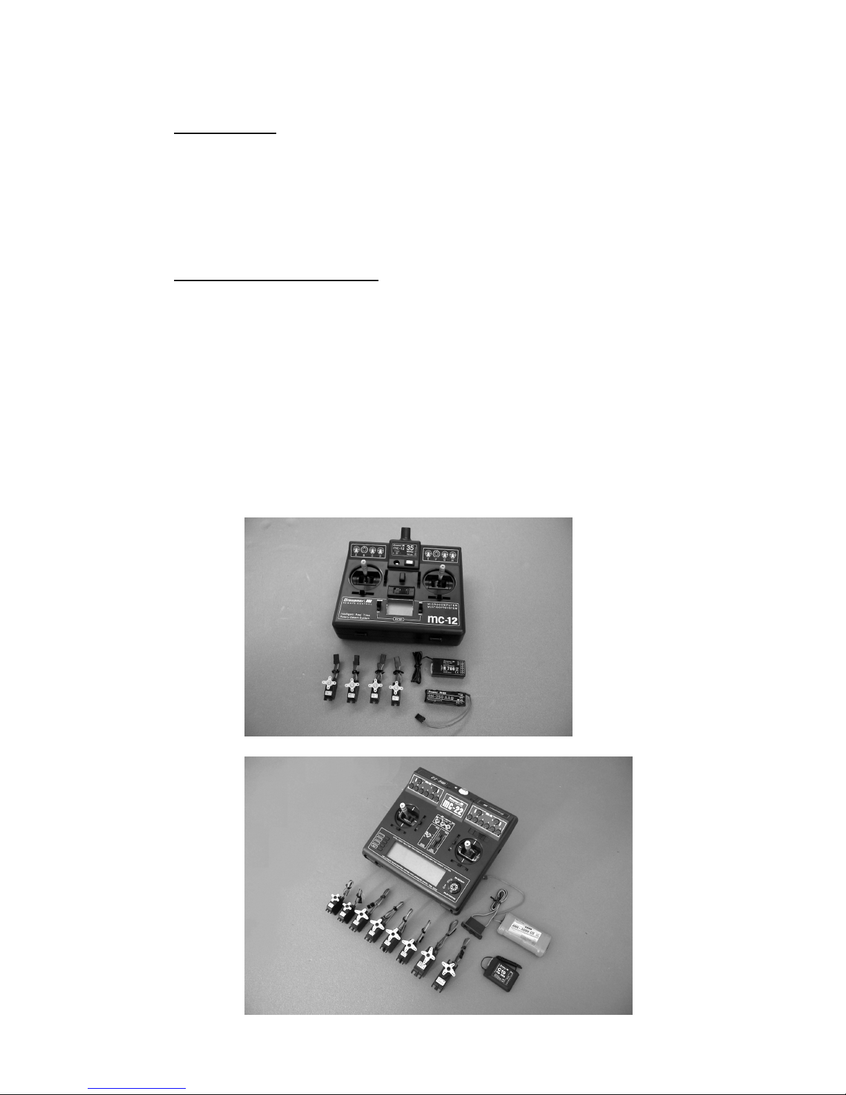
Radio Control System
Especially recommended: Computer system from mc-12 to mc-24
or
Page 7

7
Recommended servos for:
Rudder and DES 678 BB,MG order no. 7943
Elevator
Ailerons and DES 448 BB,MG order no. 7914
Wing flaps
Receiver power supply PRX-3A order no. 4135
As receiver a DS 19 or SMC 19 or SMC 14 can be used
Required servo extension cables
Order no. 3935.18 for connection to receiver (4 pieces)
For the receiver battery we recommend: Order no. 7674.2 which must always be
properly maintained and charged before and after each flight, i.e. the battery ought to
be be discharged and re-charged several times until it reaches the full specified
capacity.
Re-chargeable batteries are recommended for the receiver and transmitter as they
provide the highest level of safety. For suitable battery chargers see our catalogue.
Assembling the ALPINA 3001 CHAMP PRO
Only begin the assembly after you have familiarised yourself with the individual
components and construction stages. In the event that a component should give
reason for complaint this should be communicated to your specialist dealer prior to
the start of construction.
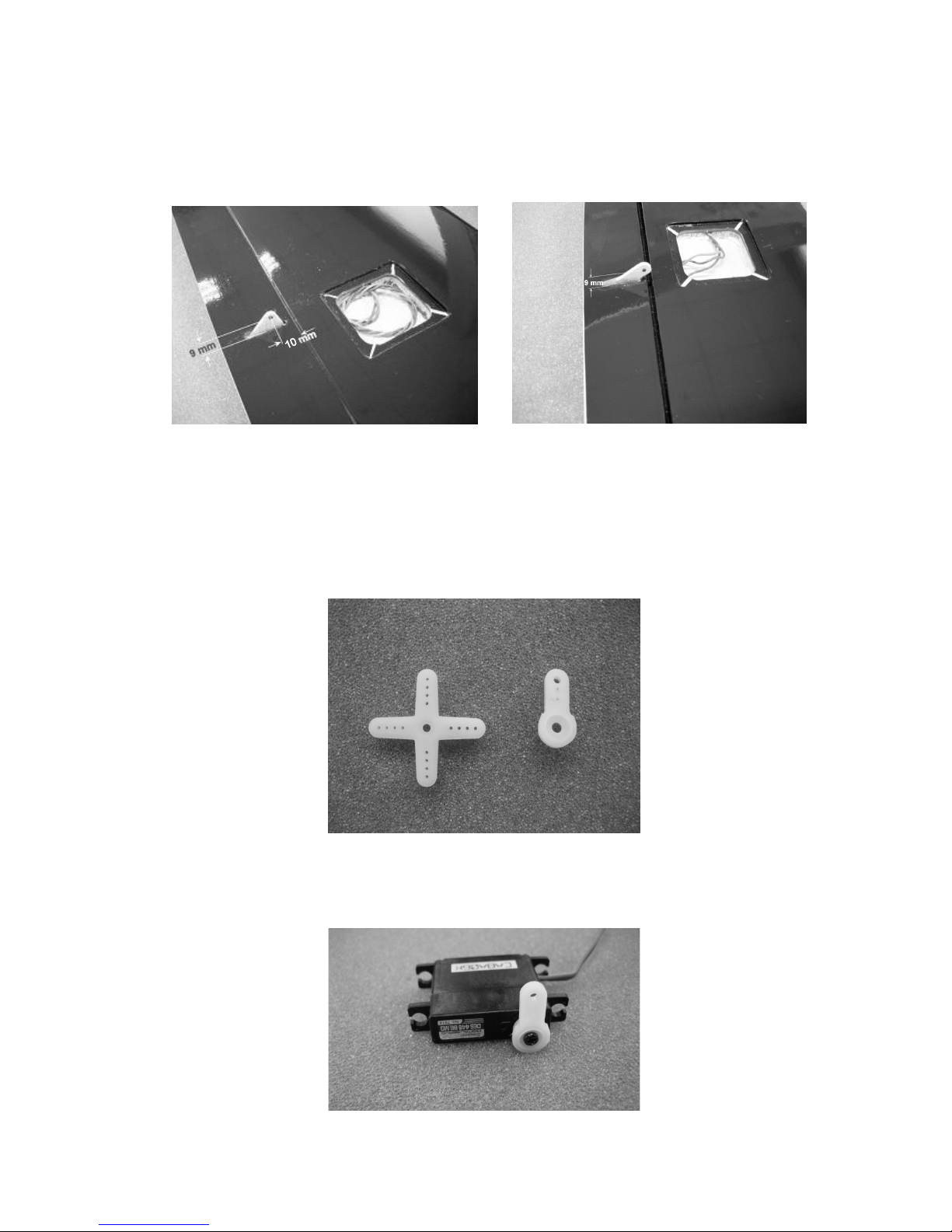
The wings
Feel with your fingertips for the servo openings for the aileron and flaps servos, then
melt them free with a hot soldering iron or cut free with a sharp balsa knife and adjust
to accomodate the control horns as nesssary. As shown in both photos glue in the
GRP control horns using suitably thickened epoxy resin.
Page 8
8
The depth of the servo openings is mechanically prefabricated; it may, however, be
necessary to adjust the depth of the openings by removing further Styrofoam (as
much as possible, until veneer with a fibre orientation transverse to the wingspan
becomes visible).
While waiting for the the adhesive to cure, prepare the servo control horns as shown
in the photo. The outer hole may need to be drilled open to a diameter of 1,6 mm to
accomodate the push-rod.
With servo in the centre (neutral) position the prepared servo levers are mounted on
each respective servo and tightly screwed down. In order to do this, place the servo
via the remote control in neutral position.
Page 9
9
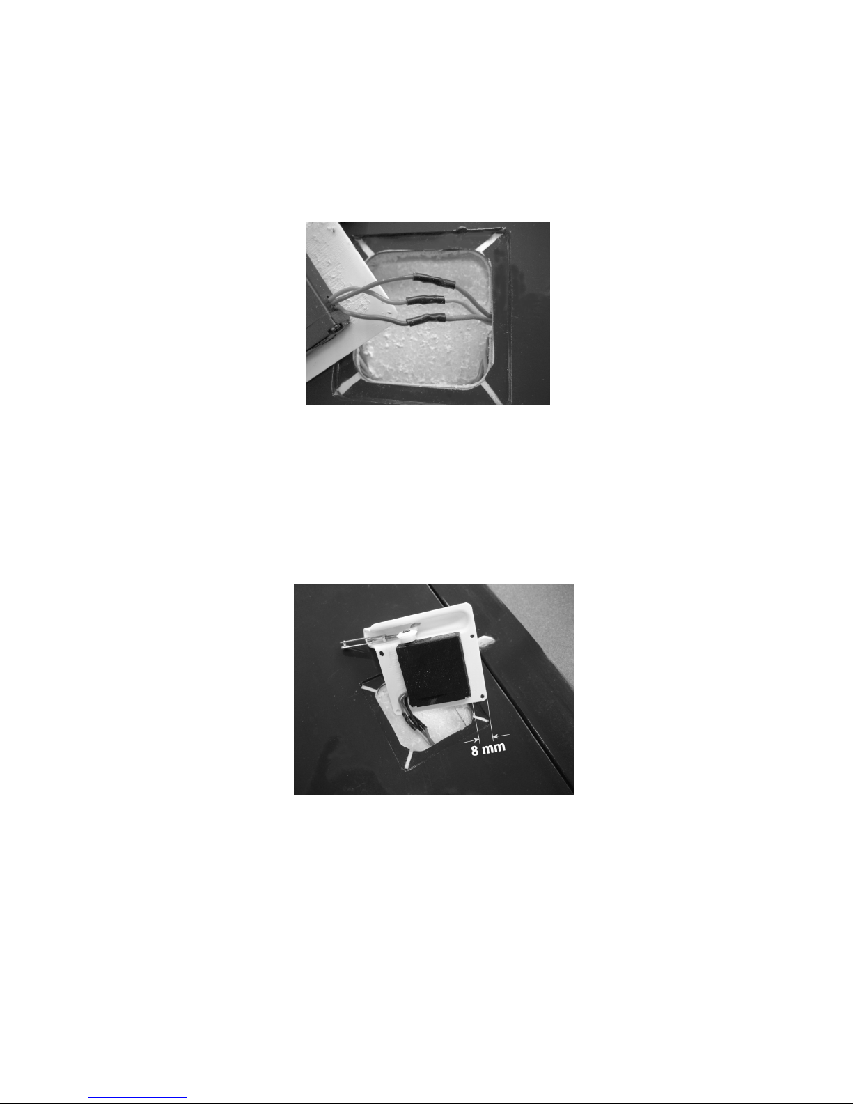
Before glueing the servos on the covers the connection cables must be soldered onto
the extension cables which have already been pre-fitted into the wings and the
mounting links must be removed from the servos. When doing so ensure that the
correct polarity is applied, i.e. the correct colour-coded cables are soldered together.
As shown in the photo isolate the soldering joints with heat shrinkable tubing which
must be pushed onto the cables before soldering.
Now the servos are glued onto the servo covers; as shown in the photo. The servo
lever must be in the centre of the output fairing and the servo must be about 8 mm
from the edge. The servo cover and the servo casing itself must be well roughened
with sandpaper. Superglue (order no. 5821) can be used as adhesive here. Ensure
that the servo is placed in the correct position at the first attempt at assembly.
Note: When using superglue it is not possible to move the item at a later stage in
order to correct its position.
The push-rods for the ailerons and wing flaps are made from the M2 threaded rods
supplied in the hardware pack and are fitted with a M2 lock nut and a M2 clevis. The
aileron push-rods must be bent so as to measure 40 mm from the mount point on the
servo lever to the clevis pin. For the wing flaps the distance must be about 45 mm.
The exact length can be adjusted after screwing the covers is adjusted by turning the
clevis in or out.
Page 10

10
For extra security, the clevis and lock-nut ought to be secured with UHU screwsafe.
Now is the time to mount the clevises in the control horns and fasten the covers using
the flat-head screws supplied in the hardware pack.
Tip: Countersink the holes to achieve good aerodyamic performance!.
There are two ways to connect the servos to the receiver: The first option is to extract
the connection cables from the openings in the fuselage and then plug them together
with the extension cables. The second option is to solder onto the connection cables
using the wing servo quick connection order nos. 2972 and 2973 whereby the servos
are automatically connected when both wing halves are assembled.
Page 11

11
The openings in both sides of the fuselage wing fairing must be opened out at the
positions marked in the molding. Ensure that you leave about 1mm space arround
the larger rectangular opening for the wing joiner.
To ensure that the wings are held secure against twisting loads at the fuselage, four
steel wing incidence pins need to be securely bondede into the wing root ribs.
Open out the holes in the root ribs to accomodfate the wing incidence pins using a
Ø 3 mm drill to a depth of about 50 mm. The the wing halves can now be dry-rigged
against the fuselage using square CFK wing joiner and the wing panels may be dry
fitted to check for allignment. Tip: Take care to avoid that the wing incedence pins are
not pushed back into the holes in the wing roots!
The wing joiner.
The wing joiner for the ALPINA 3001 Champ PRO is in the form of a carbon square
joiner in a carbon composite sleve. The wing joiner itself a high-quality carbon fibre
laminate with in-built V-shaped profile which ensures excellent load bearing
properties. In spite of high levels of standardisation there can be small tolerances in
the fit due to limitations in the production process. This is NOT a quality defect – it
can be easily adjusted, if necessary, in a few seconds using 120-grain sandpaper.
Page 12

12
Now is a good time to install the compression strut, supplied as part of the wooden
parts kit. Carefully adjust the length of the hardwood piece to fit inside the width of
the fuselage, just aft of the trailing edge incidence pins. It is important that the strut
fit snugly, without distorting the shape of the fuselage, but correcting for any minor
manufacturing tollerence in respect of the wing/fuselage fairing. The strut is
bonded into place using suitably thickened epoxy resin.
Once satisfied with the fit and allignment of the wings on the fuselage, the wing
incidence pins may be bonded into the holes in the root ribs. The pins should
protrude about 7 – 10 mm from the wing roots. Be sure to make one pin in each wing
a little longer than the other, and round off the end of the pins to facilitate easier
assembly at the flying field. Once both wings have been marked and drilled, carefully
check the alignment before bonding the incidence pins into place. Apply a suitable
release agent to the holes in the fuselage fairing before applying a suitably thickened
epoxy. Then fit the wings to the fuselage, with the steel joiner installed to allow the
epoxy to cure overnight. Tip: Use a layer of kitchen film between the wing/fuselage
joint to avoid any excess epoxy from forming a permanent joint!
To complete the work on the wing halves glue the pressure pins (multilocks) into the
blind holes in the root ribs. In order to do this, press the pressure pins into their
counterparts in the fuselage. If necessary rework the blind-holes slightly to
accomdate the pressure pins. Apply a little adhesive in the blind-holes in the root ribs
and assemble the wing on the wing joiner and allow to cure.
TIP: Once again, use a layer of kitchen film between the wing/fuselage joint to avoid
any excess epoxy from forming a permanent joint!
Fuselage and Canopy
Fit the pin carrier strip (grooved strip) into the canopy. Then deburr the edges of the
pin and bond it securely into grooved strip. The pin should protrude about 22mm
beyond the end of the carrier strip. Glue the pin/carrier assembly such that that the
pin protrudes about 6 mm beyond the edge of the canopy and a distance of about 3
mm remains, measured on the inside of the canopy. Carefully file (not too much!)
with a round file a small groove into the fuselage in the centre of the front canopy
section, into which the canopy pin will lock. The canopy retainer consists of the GRPspring. The spring protrudes 10 mm beyond the rear canopy rim. The canopy spring
is fixed with superglue and subsequently laminated over with 1-2 layers of glass-
Page 13

13
fabric tape (160 g) and resin over a length of 50 – 60 mm. be sure to roughen the
joints with sandpaper (80 grain) before bonding with a suitably thickened epoxy resin
– as shown.
When mounting the canopy to the fuselage, place the canopy onto the fuselage so
that the GRP-tongue on the rear end can firstly be pushed so far into the fuselage
that the steel pin will be pushed under the fuselage section when the canopy is
pushed forward again.
When being pushed forward the canopy self-centres automatically in the canopy
frame on the fuselage.
To install the servo tray, start by tearing off the fabric tapes on the inside of the
fuselarge.
Page 14

14
The positioning of the components installed in the nose of the fuselage will depend to
some degree on your choice of battery pack and other RC components and all of
these will influence the balance point. Carefully check the physical layout of all the
components, bearing in mind the recommended centre of gravity.
The servo mounting tray is to be located within the cockpit opening leaving sufficient
space to accomodate the receiver battery. The servo mounting tray does fit in the
fuselage opening! Turn it around carefully and you will find that it will slip neatly into
place. Don’t be tempted to apply force, or to remove too much material which will
result in a poor fit. Mark the position carefully with a pencil and tack the servo tray in
place using an instant adhesive – before bonding the frame securely into the
fuselage with a generous bead of thickened epoxy. Allow to cure. Tip: Some may
wish to complete the job by adding a layer of wetted fibre glass cloth over the entire
servo frame allowing about 10mm extra on both sides to bond with the fuselage
sides.
Prepare the servo output arms with servo in the centre (neutral) position mount them
onto the servo output shaft. Mount the servos and the ON/OFF switch onto the servo
mountin tray.
The rudder and elevator push-rods will need to be shortened such that with the
servo in the centre (neutral) position the corresponding control surface is also
located in the neutral position. Both Bowden tubes used to support the rudder and
elevator control push-rods will naturaly also need to be shortened accordingly.
This is also a good time to install the aero-tow release (if required). There is a
good selection of purpose made model aero-tow release mechanisms available
commercially for which installation techniques vary, but the simplest form is
described below:
Carefully mark out and cut a 10mm slot about 2mm wide transversally about 5cm
from the nose and with the lower third of the fuselage diameter. Using thickened
epoxy, fix a length of PVC Bowden tube along the inside of the fuselage such that
it intersects the slot at 90 degrees. The slot should be positioned so as to allow at
least 5-10mm of the PVC tube in front of the slot. Once the resin has cured, cut
away the Bowden tube from inside the slot and insert a length of steel wire inside
the tube such that it engages both sides of the slot when closed and is clear of the
slot when open. Connect the free end of the steel wire to a suitable servo to
Page 15

15
operate the aero-tow release. You will require a simple loop, best made from
monofilament nylon to link up to the towline.
The winch hook
Measure and mark a point on the belly of the fuselage 55 mm from leading edge of
the wing fairing – as shown. Drill a 2.5mm hole to accommodate the winch hook.
Cover the hole on the outside with tape to protect the surface and roughen up the
inside of the fuselage in the area of the hole. Now glue the tow hook support block
into place centrally over the hole using thickened epoxy. Use a self tapping screw,
through the hole in the bottom of the fuselage to secure the support block while the
epoxy cures. Tip: for additional security, you may wish to finish the job by laminating
the support block to the fuselage bottom using 2-3 layers of suitably wetted 120g
fibreglass laminating cloth. Once the support block has thoroughly cured, drill a Ø 2
mm pilot hole to accommodate the supplied winch hook.
Page 16

16
The all-flying tailplane
The elevator bell-crank in this model is already pre-installed and ready for use. It may
only be necessary to slightly rework the groove milled onto the vertical stabiliser. The
tailplane halves are fitted using both Ø 3 mm steel wires. Push one steel wire through
the locating hole into the fin, the second through the milled groove in the fin and
bellcrank. Now both tailplane halves can be pressed fully home onto the steel wires.
CAUTION! Before pushing the tailplane halves onto the steel wires for the first time
these must by all means be checked for absence of burr. The tailplanes contain a
built-in locking system which may be damaged by burred edges on the wires and use
of excessive force.
CAUTION! With regard to the ARC-version of the model please ensure that the
tailplane is assembled with the correctly, with the upper-side of the elevator
uppermost. You can identify the upper-side by its dot marking at the root rib.
The Rudder
Locate and open-up the two hinge points along the leading edge of the rudder and
carefully mark the corresponding hinge points along the centre of the rudder post.
Now drill the holes using a Ø 3.5 mm drill to accommodate eye-bolts used to form the
hinge and screw these into the rudder post, but do not bond in place just yet. Insert
the GRP hinge pin through the guide tube located in the leading edge of the rudder
such that it passes through the three holes in the eye-bolts – to form an effective
hinge. Now carefully check the movement and throw of the rudder with respect to the
fin and adjust the depth of the hinge, by screwing in (or out) the three eye-bolts until
you find the optimum depth. Mark the position of the eye-bolts before bonding into
place using a suitably thickened epoxy, re-install the rudder and adjust as necessary
before finally allowing the hinge points to set. Tip: It is possible to unscrew the hinge
bolt and reset it with a little more adhesive should you find it necessary to make an
adjustment after the hinge bolts have been set into the fin post.
Page 17

17
Next, carefully mark out the position of the rudder control horn to align with the
shroud in the rear of the fuselage and the rudder control linkage. Try to locate the
horn as close as possible to the pivot line, and at exactly 90 degrees to the rudder
hinge line. Take care to avoid any restriction caused by the rudder horn touching the
shroud in the fuselage. Now drill a 4 mm hole at the point where the rudder horn is to
be installed. The hole should be as deep as possible but take care not to pierce the
skin on the other side of the rudder. Undermine the hole using a sharp tool so as to
increase area available to the adhesive and bond the rudder horn into place using
suitably thickened epoxy.
Assembly of the ALPINA 3001 CHAMP PRO
Insert the wing joiner through the fuselage opening and press the wings firmly onto
the joiner, ensuring that all four wing incedence pins and the pressure pins have fully
engaged and all wing servo connections have been secured. Insert both tailplane
halves on the steel wires and check that they are secure.
Important: The tailplane and wings must be fastened to the fuselage so they
are immoveable.
Finishing
Caution!!!
The Alpina – just like other models we produce - is manufactured using very
sophisticated Load Specific Covering Thickness Procedure (LTSCP)-technology in
order to achieve the desired optimal relationship between of weight and strength. In
this process, the thickness of wing skins are carefully reduced towards the tips which
means that the thermal diffusivity is considerably enhanced! Particular care must be
taken when using heat-shrink covering films to decorate your model. You should by
all means use covering films which have a low melting point so as not to destroy the
underlying polystyrene core (polystyrene melts at temperatures greater than 70°C).
When using heat-shrink covering films you should make every effort to avoid
prolonged exposure to heat.
We therefore recommend preferably low temperature covering films such as for
example adhesive foils.
Page 18

18
Balancing the ALPINA 3001 CHAMP PRO
Support the completely equipped, airworthy model, right and left next to the fuselage,
about 84 mm behind the root wing leading edge. The model should now balance
itself horizontally, or as the case may be, the nose pointing slightly downwards. If
additional nose weight is required, use a measured amount of Lead (Lead shot is the
most convenient form) and fix it into the nose with suitably thickened epoxy resin
.
The correct longitudinal dihedral (decelage) is +1 to +1,3°. This is the angle of the
elevator (at the neutral position) with respect to the wing and is best measured with
the aid of an incidence meter.
The following recommended control throws have been determined following several
test flights, confirmed by several different model pilots. We strongly recommend that
you begin with the recommended throws and only change them with experience
.
Control Throws:
Ailerons plus 25 mm up minus 10 mm down
Elevator plus 10 mm up minus 10 mm down
Rudder plus 10 mm left minus 10 mm right
Thermal Position
Ailerons minus 1,5 mm down
Flaps minus 3 mm down
Speed Position
Ailerons plus 2 mm up
Flaps plus 1,5 mm up
Butterfly Position
Ailerons plus 18 mm up
Flaps minus 65 mm down
Elevator minus 3 mm down
Tip: The specified control throws may be further adjusted via the Dual Rate function
of the transmitter.
Page 19

19
Important:
When installing the control push-rods always take great care that they run easily,
and to their full extent – including trimming – and are in no way mechanically
restricted.
When moving the rudder-control stick to the right, the rudder must swing to the right,
when moving it to the left, it must swing to the left. When moving the elevator control
stick back, both elevators must move upwards (pitch up). When moving the aileroncontrol stick to the right, the right aileron must move up, the left one downwards.
When moving the butterfly-control stick back the ailerons must swing upwards and
the flaps downwards. The flaps are best operated via a slider with an electronically
restricted path, so that for a full path of the slider the specified throws are achieved.
The First Flight
Experienced model flyers will now take the first opportunity to go to the model airfield
and test fly their model in the usual manner, make final corrections and then
hopefully have much fun and success flying their Alpina 3001 CHAMP PRO.
Some tips from the practice of modelflying should help you to make the most of the
wide variety of application possibilities for this model.
Test Flying
Every flying machine, from model aircraft to passenger carrying planes, must be test
flown after completion. This also applies to your Alpina 3001. The slightest deviation
in manufacture or construction can lead to minor variations in flying characteristics
and control responses. Test flying is the means to optimise the centre of gravity and
to generally fine-tune the control response.
Avoid by all means unnecessary low altitude hand launches on a flat site. While
doing so the model is flying close to the ground in the most dangerous zone as there
is little time to make adequate corrections and damages are most likely to occur.
The Range Test (also for experts!)
Ensure that both transmitter and receiver batteries are fully and properly charged.
Before switching on the transmitter ensure that the channel you are using is free. The
channel pennant on your antenna is obligatory and indicates your channel to other
pilots! If other pilots are present, announce your channel loudly and clearly.
Carry out a range test before the first flight. You should always carry out this test as a
matter of principle before commencing each days flying. Hold the model in a way that
the antenna is not affected – at the tip of the fuselage is best. An assistant walks
away with the transmitter. While doing so the antenna is fully pushed in. While
walking away operate a control function. Observe the other servos. The uncontrolled
servos should remain stationary up to a distance of at least 80 m and the controlled
servo must follow the controlled movements without delay. Should this not be the
case check again if your channel is free. If this is the case, return the entire system
(with battery, switch cable, servos etc.) to the service department of the manufacturer
for inspection.
Page 20

20
Faults do not cure themselves!
This test can only be carried out if the wireless band is undisturbed and no further
remote control transmitters are being operated, even on other channels! Such trials
are not advisable on high mountains due to the extremely strong field strengths and
overshoots by other transmitters. If you are unsure about anything do not under any
circumstance fly your model, even if you are very keen to try it out and the spectators
demand a first flight demonstration.
The First Start
The first flight can be carried out in different ways: at a slope site from a hand launch,
at a flat-field site or via an aero-tow.
Aerotow is the best (safest) method to launch your Alpina 3001 for the first time. Do
not forget the usual arrangements between you and your tug pilot!
At a slope site: Wait for a good upwind phase and throw the model diagonally
downwards. Let the model initially flop – gaining speed is half the battle! If necessary
adjust the trims to achieve straight and level flight and maintain speed. Then fly
control switch curves to test cornering characteristics, control throws (roll, pitch and
yaw). Be sure to extend the air breaks/flaps briefly at height to get to know the
behaviour of the model.
If there is sufficient height, check the centre of gravity at the same time. The
procedure for checking the centre of gravity described in the following is a fine-tuning
of the centre of gravity. This method requires gentle airflow and a precisely balanced
centre of gravity; it fails in strong winds or when severe balancing errors are made.
During strong winds it is very difficult to trim the normal speed as it is very hard to
estimate the actual speed in relation to the ambient air.
The model is being trimmed in normal speed; this is considerably higher than the
pitch speed. The model must not undulate or appear "spongy" and heavy to control.
The flaps are on "neutral".
Now – provided the model is flying at a safe height – briefly apply down elevator to
place the model in a steep dive. Then allow the elevator to return to neutral
immediately and observe the flight path. The centre of gravity can be considered to
be about right if the model recovers in a gentle upward arc (100 m) without any
further control inputs.
The centre of gravity is too far forward if the model bounces quickly out of the dive
and climbs steeply.
Action: Remove lead ballast from fuselage nose, trim depth a little.
The centre of gravity is too far back if the model shows no tendency to recover, or
indeed if it even begins a steeper nosedive.
Action: Intercept the model immediately. Add lead to the fuselage nose and secure,
trim height a little.
Page 21

21
Flight on a flat-field site
Flying on a flat-field site is relatively safe – without the risk of sinking which you may
experience when flying at a slope site.
It takes an experienced model pilot to be able to exploit thermal lift. Due to the higher
altitudes strong lift areas are harder to recognise by observing the flight
characteristics of the model on a flat-field site than at a slope site, where "beards"
can be found at eye level. Only the most skilled pilots are able to recognise a strong
lift area on a flat-field site directly "overhead" and fly it; therefore always and look for
it at a transve distance from your position.
The flight characteristics of your model allow you to recognise a strong lift areas. If
the thermal is good a strong climb is recognisable, weak lift areas require a trained
eye and a skilled pilot. After some practice you will be able to recognise the trigger
points for the thermals. The air warms up - depending on the reflective power of the
ground more or less strongly - and air flows driven by the wind closely above the
ground. The roughness of the terrain, a shrub, a tree, a fence, a forest edge, a hill, a
passing car, even on your landing model aircraft may cause warm air to lifted from
the ground and rise upwards. A fitting comparison in the reverse sense is the
travelling water drop on the ceiling which initially remains stuck to the ceiling, pushes
against some roughness and then falls down.
The most distinctive thermal triggers are sharply defined snow fields on mountain
slopes. Above the snow field the air is cooled down and flows downwards, on the
downhill side of the snowfield edge this meets the warm air flowing slopeside up and
replaces it abruptly. This results in strong climbs, but at the same time rough thermal
bubbles. The rising warm air is to be detected and "centred". When doing so the
model should by control corrections be kept in the centre of the lift area as the
strongest climb values are to be expected there. However, this requires some
practice.
Leave the climbing zone at the right time in order to avoid visibilty difficulties.
Remember that the model can be seen better under clouds than in the blue,
cloudfree areas. If height must be reduced consider the following:
The stability of the Alpina 3001 Champ is quite high, but there are limits. High speed
flights in the F3B-manner should only be attempted if the flaps are in neutral
position! A GRP-coating extends the speed range and the application possibilities of
the model.
Start the landing at a relatively high altitude and overcome the dangerous zone at low
altitude quickly and safely using the airbreaks/flaps. A correctly flown landing
approach – consisting of a parallel flight with the wind away from the pilot, a traversal
flight and a straight, butterfly-supported landing approach with subsequent catch for
landing – ensures the safety of the model, pilot and spectators.
Page 22

22
Flight at a slope site
Flights at a slope site are a particularly attractive type of model glider flying. Flying for
hours in the slope winds without external launching assistance is one of the most
enjoyable experiences. The highlight is the thermal flying from a slope. To launch the
model, fly out over the valley, seek thermal, find thermal, circle high up to the visibilty
limit, then bring down the model by acrobatics only to start the game over again is
model flying in perfection.
But beware, as slope flying can also harbour dangers for the model. Firstly, the
landing is in most cases considerably more difficult than on a flat-field site. Often the
landing must take place in the lee of a mountain, which requires concentration and a
spirited approach with crossing and subsequent air brake landing. A windward
landing, that is in the immediate upwind, is even more difficult; it should always be
carried out uphill, with crossing and timely catch shortly before landing.
Another danger is the lack of upwind or thermal at the most inconvenient moment,
which harbours the risk of a difficult landing in the valley. This risk can, however, be
reduced by obtaining information about a potentially necessary landing site in the
valley before the start of the flight and by personally inspecting this site in advance in
order to get to know any obstacles for the approach and local wind conditions. If the
landing cannot be avoided the landing should be carried out as in the flat field with a
landing approach and a short, straight end approach with air brake support. Always
fly the model in the visibility axis above the intended landing site. By doing so you will
avoid a too short landing and arrive safely at the landing site. If the sun shines you
can estimate the height from the early visible shadow of the model. With this
assistance even spot landings are possible in the valley.
Never give up!
Thermals can be found even at the lowest altitudes. Once the end approach has
been begun the landing should take place under any circumstance, as in this case
the altitude is really too low for thermals. Calmly memorise the landing site and how
to get there, maybe there are distinctive features in the terrain which you can aim for
in your later search.
The main thing about thermal search under launch height is, however, to "keep
calm". Realise that in most cases the pilot is the problem, not the model. Also reduce
any "helper" to silence who stands next to you and continuously and obtrusively
offers "good advice". A pilot who really wants to help you gives only very short and
really helpful hints, e.g. about other models whose pilots have found thermal, a
circling bird of prey or the safe approach to the intended landing site. Perhaps he
even launches his model, flies it down to the valley and helps with the thermal
search. The chances of success increase considerably if two models are being flown.
Page 23

23
Safety
Safety must always remain of paramount importance when flying model aircraft.
Liability insurance is obligatory. If you join a club or association you can take out
insurance there. Ensure that you get sufficient insurance cover. Always keep models
and remote controls in optimal working order. Familiarise yourself with the charging
technology of the batteries you use. Make use of all the sensible safety installations
which are on offer. Obtain information from different product catalogues and from
your local model-making specialist dealer.
Fly your model responsibly! To fly over other people’s heads is no sign of real skill.
The real expert won’t need such displays of vanity. Remind other pilots – in
everyone’s interest – about this fact. Always fly in a way that neither endangers you
nor others. Always remember that even the best remote control can be disturbed by
external influences. Even many years of accident-free flying experience are no
guarantee for what might happen in the next flight minute.
Fascination
Get to know your Alpina 3001 Champ PRO, its excellent performance, comfortable
flight characteristics and enormous range.Enjoy one of the few sports in which the
combination of technology coupled with your own skill – whether on your own or with
friends - and the conditions of Mother Nature are combined to provide enjoyable
experiences which have become rare in our present times.
We at GRAUPNER/TANGENT-model sport, wish you much pleasure and success
building and flying your new model!
GRAUPNER / TANGENT – Modellsport
Dieter Bär – Modellentwicklung
Page 24

24
Parts List
Qty Description Purpose Material Dimension
1 Assembly instructions Paper DIN A4
1 Epoxy Fuselage GRP white ready made
1 Canopy GRP ready made
1 Set wing panels Styro/Abachi ready made
1 Tailplane Styro/Balsa ready made
1 Rudder Balsa ready made
1 Wire set Metal/Plastic Parts list
1 Set wooden parts Wood Parts list
1 Accessory parts Miscell. Parts list
1 Set servo locks Plastic/wood Parts list
1 Wing Joiner CFC 20x12x227
Wire set
2* Steel wire Rudder/Elevator Spring Steel Ø 1,4x1200
1 Steel wire Aero-tow coupl. Spring Steel Ø 1,4x160
1 Bowden tube Aero-tow coupl. Plastic Ø3,2x350
1 Rudder bearings CFC Ø2,0y420
* Rudder/Elevator push-rods are pre-installed in the fuselage!
Wooden Parts
1 Servo mounting tray Fuselage Abachi 210x85x3 mm
1 Compression strut Fuselage Plywood 75x10x10 mm
1 Glider hook holder Fuselage Hardwood 50x15x15 mm
Accessories
3 Threaded bushing Rudder linkage Steel M2
7 Clevis Rudder linkage Steel M2
4 Threaded rods Rudder linkage Steel M2
2 Rudder horns aileron Rudder linkage GRP milled piece
2 Rudder horns Flap Rudder linkage GRP milled piece
1 Rudder horn Rudder linkage Alumin. M4/1,6
2 Eye bolt Rudder hinge Alumin. M4/2,05
6 Lock nuts Control linkages Brass M2
2 Pressure pin (multilock) Wing Plastic
1 Elevator joiner Elevator/Fuselage Steel Ø3x130
1 Elevator joiner Elevator/Fuselage Steel Ø3x100
4 Torsion pins Wing Steel Ø3x60
1 Glider hook Fuselage Steel Ready made
1 Self tapping screw Fuselage Steel M4x25
1 SPAX-screw Fuselage Steel Ø3x16
Note: Contents and technical details may be subject to change without notice
Page 25

25
Before the attempt of a first flight the entire operation and assembly
instructions must be read carefully. You alone are responsible for the safe
operation of your RC-model aircraft. The construction and operation of the
model must be supervised by a responsible adult who is familiar with the
conditions and potential dangers of a RC-model aircraft. Any questions relating
to safety issues when operating a RC-model aircraft will be happily answered
by specialist dealers.
Remote control model aircraft are very sophisticated and dangerous objects
and require high levels of expertise, skill and responsibility on the part of their
operators.
Legally, a model aircraft is an aircraft and subject to the relevant laws and
regulations which must by all means be complied with. The brochure
»
Model
flight law, clauses and more«, order no. 8034.02 is a summary of these laws
and regulations; it can also be viewed at specialist dealers. Furthermore, postal
restraints which relate to remote control systems must be observed. Relevant
advice can be found in the operating instructions of your remote control
system.
Only parts supplied in the construction kit as well as genuine Graupner
accessories and parts which are expressly recommended by us are to be used.
If only one component of the drive unit is changed a safe operation cannot be
guaranteed and any potential claim under warranty is invalidated. Only use
fitting, reverse polarity protected plugs. Avoid short-circuits and incorrect
polarity. Due to the high energy of the NiMH-batteries there is a risk of
explosions and fires.
A RC-model aircraft can only be functional and meet your high expectations if
it has been carefully built according to the assembly instructions. Only
cautious and thoughtful handling when operating the model protects against
personal injury and damage to property. Nobody would try to fly a glider plane
without previous training. This also applies to model flying. However, the
manufacturer has no means to influence the construction and the operation of
a RC-model aircraft. We therefore emphasise strongly the dangers and hereby
reject any liability for this.
Please seek assistance and advice from experienced model flyers, clubs or
model flight schools. Furthermore we would like to refer you to specialist
dealers and relevant publications for additional information. It is best to fly as a
member of a club on a licensed model airfield.
Adhesives and varnishes contain solvents which may damage your health.
Always observe the relevant notes and warnings of the manufacturers.
The operator must be in full possession of his or her physical and mental
abilities. Just as with driving a car the operation of a model aircraft under the
influence of alcohol or drugs is prohibited by law.
Before operation inform all passers-by and spectators about any potential
dangers which may originate from your model.
Page 26

26
Always keep the necessary safe distance to people or objects; never fly low
over people’s heads or directly towards people!
Model flying must only be carried out at outside temperatures of between - 5º C
and + 35º C. More extreme temperatures can lead to changes of material
properties such as the battery capacity and defective adhesive connections.
Every model flyer must conduct him-/herself in such a way that public safety
and order, especially regarding other people and objects, as well as the order
of the model flight operation are not endangered or disturbed.
Never fly the model aircraft near high-voltage power lines, industrial estates,
in residential areas, public streets and places, school yards, parks and
playgrounds etc.
Warnings must always be observed. They refer to things and processes which
can lead to severe damage or injuries which in extreme cases can be fatal.
Prior to each operation of the model check that all plugged-in connections
such as e.g. radio control components, rudder horns etc. are secured tightly
and examine them for potential damage. Only after the elimination of all
defects is the model to be operated.
Ensure sufficient stability when holding the model in your hand. Wear suitable
sturdy shoes, e.g. trainers.
Only switch on the remote control after you have made sure that the used
frequency is free! Radio interference caused by unknown people can always
occur without warning. This can result in the model being out of control and
unpredictable! Never leave the remote control system unattended to avoid it
being operated by a third party.
The flight position of the model must always be clearly identifiable throughout
the entire flight in order to guarantee safe control. If malfunction or
disturbances are noticed during the flight the landing must be initiated
immediately for safety reasons. You must always give way to other aircraft.
Launching and landing areas must always be clear of people or other
obstacles.
Always ensure that the batteries are fully charged as otherwise faultless
functioning of the RC-system cannot be guaranteed. Never use hot, faulty or
damaged batteries. Always follow the instructions for use of the battery
manufacturers.
Before each flight check the complete RC-system as well as the model aircraft
for full operational reliability and carry out range checks.First switch on the
transmitter and then the receiver system. Equally, first switch off the receiver
system, then the transmitter. Check that the control surfaces move correctly,
according to the operation of the controller.
Page 27

27
Take all batteries out of the model after use and store only in discharged mode
(ca. 0,9 V pro cell) at temperatures between + 5º and + 25º C. Keep batteries
out of the reach of children.
These notes are meant to alert you to the many dangers which can result from
incorrect and irresponsible handling. When practised properly and
conscientiously model flying is a creative, educational and relaxing leisure
activity.
Notes regarding the use of NiMH-batteries
Application area
All Graupner NiMH-batteries as well as NiMH-individual cells are exclusively suited
for model-making purposes such as for model aircraft, ships or cars.
Charging
1. Charge the NiMH-battery with a suitable charger or fast charger (see chargers in
the Graupner- main catalogue FS).
2. Before charging the battery must have cooled down to a temperature of around
20° C. If necessary use the cooling appliance BATTERY COOLER, order no.
2882 for cooling down the battery.
3. Charge the battery only immediately before use. Each NiMH-battery is subject to
a slight auto-discharge for technical reasons.
4. Warning:
The charging process must be supervised even with fully automatic chargers.
Observe the maximum permissible charging current displayed on each battery or
individual cell. If the charging current is too high the NiMH-cells overheat. If the
battery heats up to 50° C during the charging process the charging current must
be interrupted immediately. By overheating of the NiMH-cells the overpressure in
the cell casing increases considerably. Each individual NiMH-cell of a battery is
equipped with an overpressure valve which protects the cell in emergencies from
a dangerous explosion. It is, however, possible that due to unpredictable
circumstances a valve will not function correctly so that an explosion may happen
in case of excessive overheating of the cell.
5. Warning:
Do not touch accidentally overcharged NiMH-batteries, but interrupt the
charging current and allow the battery to cool down.
6. Warning:
Avoid short-circuits by all means as the battery heats up immediately in the case
of an extremely fast discharge such as a short-circuit which can cause a cell
explosion just as in the case of overcharging. There is the risk of injury by
explosion and cauterisation from the electrolyte in the cell.
Avoid any skin or eye contact with leaked electrolyte. In an emergency rinse with
plenty of water and seek medical help.
7. Never solder cables or any similar objects directly onto the cell casing as this may
damage the overpressure valve.
8 Warning:
Never throw faulty or old NiMH-batteries into the fire.
Page 28

28
Do not throw away batteries in your household waste, but dispose of them safely
in the appropriate recycling containers. This is free and protects the environment
as most of the battery components can be recycled.
Notes regarding the construction and operation of the ALPINA 3001 Champ
PRO Before commencing the construction process:
Radio Controlled parts as well as controll push-rods are installed during assembly
according to the relevant construction stage. The installation at a later stage is either
not possible at all, or only with great difficulty.
When buying a radio remote control ensure that the transmitter and receiver
appliances are suitable for model aircraft, are licensed by the Deutsche
Bundespost-Telekom and have a Foreign Trade Zone (FTZ)-serial test number.
Other radio installations and high frequency appliances are also operated in the
frequency ranges for radio remote controls. Therefore no protection against
disturbances by such appliances can be granted.
The operation of radio remote controls for model aircraft on the authorised channels
in the 35 MHz-band is chargeable, i.e. the radio remote control must be registered
with the Deutsche Bundespost-Telekom.
Further information about this topic is available from your local Telecom-branch or at
your model-making specialist dealer.
 Loading...